EP3291771B1 - Implantathalter - Google Patents
Implantathalter Download PDFInfo
- Publication number
- EP3291771B1 EP3291771B1 EP16721554.0A EP16721554A EP3291771B1 EP 3291771 B1 EP3291771 B1 EP 3291771B1 EP 16721554 A EP16721554 A EP 16721554A EP 3291771 B1 EP3291771 B1 EP 3291771B1
- Authority
- EP
- European Patent Office
- Prior art keywords
- impaction
- tip
- implant
- handle
- sliding member
- Prior art date
- Legal status (The legal status is an assumption and is not a legal conclusion. Google has not performed a legal analysis and makes no representation as to the accuracy of the status listed.)
- Active
Links
Images





Classifications
-
- A—HUMAN NECESSITIES
- A61—MEDICAL OR VETERINARY SCIENCE; HYGIENE
- A61F—FILTERS IMPLANTABLE INTO BLOOD VESSELS; PROSTHESES; DEVICES PROVIDING PATENCY TO, OR PREVENTING COLLAPSING OF, TUBULAR STRUCTURES OF THE BODY, e.g. STENTS; ORTHOPAEDIC, NURSING OR CONTRACEPTIVE DEVICES; FOMENTATION; TREATMENT OR PROTECTION OF EYES OR EARS; BANDAGES, DRESSINGS OR ABSORBENT PADS; FIRST-AID KITS
- A61F2/00—Filters implantable into blood vessels; Prostheses, i.e. artificial substitutes or replacements for parts of the body; Appliances for connecting them with the body; Devices providing patency to, or preventing collapsing of, tubular structures of the body, e.g. stents
- A61F2/02—Prostheses implantable into the body
- A61F2/30—Joints
- A61F2/46—Special tools for implanting artificial joints
- A61F2/4603—Special tools for implanting artificial joints for insertion or extraction of endoprosthetic joints or of accessories thereof
- A61F2/4609—Special tools for implanting artificial joints for insertion or extraction of endoprosthetic joints or of accessories thereof of acetabular cups
-
- A—HUMAN NECESSITIES
- A61—MEDICAL OR VETERINARY SCIENCE; HYGIENE
- A61F—FILTERS IMPLANTABLE INTO BLOOD VESSELS; PROSTHESES; DEVICES PROVIDING PATENCY TO, OR PREVENTING COLLAPSING OF, TUBULAR STRUCTURES OF THE BODY, e.g. STENTS; ORTHOPAEDIC, NURSING OR CONTRACEPTIVE DEVICES; FOMENTATION; TREATMENT OR PROTECTION OF EYES OR EARS; BANDAGES, DRESSINGS OR ABSORBENT PADS; FIRST-AID KITS
- A61F2/00—Filters implantable into blood vessels; Prostheses, i.e. artificial substitutes or replacements for parts of the body; Appliances for connecting them with the body; Devices providing patency to, or preventing collapsing of, tubular structures of the body, e.g. stents
- A61F2/02—Prostheses implantable into the body
- A61F2/30—Joints
- A61F2002/30001—Additional features of subject-matter classified in A61F2/28, A61F2/30 and subgroups thereof
- A61F2002/30316—The prosthesis having different structural features at different locations within the same prosthesis; Connections between prosthetic parts; Special structural features of bone or joint prostheses not otherwise provided for
- A61F2002/30329—Connections or couplings between prosthetic parts, e.g. between modular parts; Connecting elements
- A61F2002/30383—Connections or couplings between prosthetic parts, e.g. between modular parts; Connecting elements made by laterally inserting a protrusion, e.g. a rib into a complementarily-shaped groove
-
- A—HUMAN NECESSITIES
- A61—MEDICAL OR VETERINARY SCIENCE; HYGIENE
- A61F—FILTERS IMPLANTABLE INTO BLOOD VESSELS; PROSTHESES; DEVICES PROVIDING PATENCY TO, OR PREVENTING COLLAPSING OF, TUBULAR STRUCTURES OF THE BODY, e.g. STENTS; ORTHOPAEDIC, NURSING OR CONTRACEPTIVE DEVICES; FOMENTATION; TREATMENT OR PROTECTION OF EYES OR EARS; BANDAGES, DRESSINGS OR ABSORBENT PADS; FIRST-AID KITS
- A61F2/00—Filters implantable into blood vessels; Prostheses, i.e. artificial substitutes or replacements for parts of the body; Appliances for connecting them with the body; Devices providing patency to, or preventing collapsing of, tubular structures of the body, e.g. stents
- A61F2/02—Prostheses implantable into the body
- A61F2/30—Joints
- A61F2002/30001—Additional features of subject-matter classified in A61F2/28, A61F2/30 and subgroups thereof
- A61F2002/30316—The prosthesis having different structural features at different locations within the same prosthesis; Connections between prosthetic parts; Special structural features of bone or joint prostheses not otherwise provided for
- A61F2002/30329—Connections or couplings between prosthetic parts, e.g. between modular parts; Connecting elements
- A61F2002/30383—Connections or couplings between prosthetic parts, e.g. between modular parts; Connecting elements made by laterally inserting a protrusion, e.g. a rib into a complementarily-shaped groove
- A61F2002/3039—Connections or couplings between prosthetic parts, e.g. between modular parts; Connecting elements made by laterally inserting a protrusion, e.g. a rib into a complementarily-shaped groove with possibility of relative movement of the rib within the groove
- A61F2002/30398—Sliding
-
- A—HUMAN NECESSITIES
- A61—MEDICAL OR VETERINARY SCIENCE; HYGIENE
- A61F—FILTERS IMPLANTABLE INTO BLOOD VESSELS; PROSTHESES; DEVICES PROVIDING PATENCY TO, OR PREVENTING COLLAPSING OF, TUBULAR STRUCTURES OF THE BODY, e.g. STENTS; ORTHOPAEDIC, NURSING OR CONTRACEPTIVE DEVICES; FOMENTATION; TREATMENT OR PROTECTION OF EYES OR EARS; BANDAGES, DRESSINGS OR ABSORBENT PADS; FIRST-AID KITS
- A61F2/00—Filters implantable into blood vessels; Prostheses, i.e. artificial substitutes or replacements for parts of the body; Appliances for connecting them with the body; Devices providing patency to, or preventing collapsing of, tubular structures of the body, e.g. stents
- A61F2/02—Prostheses implantable into the body
- A61F2/30—Joints
- A61F2002/30001—Additional features of subject-matter classified in A61F2/28, A61F2/30 and subgroups thereof
- A61F2002/30316—The prosthesis having different structural features at different locations within the same prosthesis; Connections between prosthetic parts; Special structural features of bone or joint prostheses not otherwise provided for
- A61F2002/30329—Connections or couplings between prosthetic parts, e.g. between modular parts; Connecting elements
- A61F2002/30476—Connections or couplings between prosthetic parts, e.g. between modular parts; Connecting elements locked by an additional locking mechanism
- A61F2002/30484—Mechanically expandable devices located on the first prosthetic part for locking into or onto the second prosthetic part
-
- A—HUMAN NECESSITIES
- A61—MEDICAL OR VETERINARY SCIENCE; HYGIENE
- A61F—FILTERS IMPLANTABLE INTO BLOOD VESSELS; PROSTHESES; DEVICES PROVIDING PATENCY TO, OR PREVENTING COLLAPSING OF, TUBULAR STRUCTURES OF THE BODY, e.g. STENTS; ORTHOPAEDIC, NURSING OR CONTRACEPTIVE DEVICES; FOMENTATION; TREATMENT OR PROTECTION OF EYES OR EARS; BANDAGES, DRESSINGS OR ABSORBENT PADS; FIRST-AID KITS
- A61F2/00—Filters implantable into blood vessels; Prostheses, i.e. artificial substitutes or replacements for parts of the body; Appliances for connecting them with the body; Devices providing patency to, or preventing collapsing of, tubular structures of the body, e.g. stents
- A61F2/02—Prostheses implantable into the body
- A61F2/30—Joints
- A61F2002/30001—Additional features of subject-matter classified in A61F2/28, A61F2/30 and subgroups thereof
- A61F2002/30316—The prosthesis having different structural features at different locations within the same prosthesis; Connections between prosthetic parts; Special structural features of bone or joint prostheses not otherwise provided for
- A61F2002/30329—Connections or couplings between prosthetic parts, e.g. between modular parts; Connecting elements
- A61F2002/30476—Connections or couplings between prosthetic parts, e.g. between modular parts; Connecting elements locked by an additional locking mechanism
- A61F2002/30507—Connections or couplings between prosthetic parts, e.g. between modular parts; Connecting elements locked by an additional locking mechanism using a threaded locking member, e.g. a locking screw or a set screw
-
- A—HUMAN NECESSITIES
- A61—MEDICAL OR VETERINARY SCIENCE; HYGIENE
- A61F—FILTERS IMPLANTABLE INTO BLOOD VESSELS; PROSTHESES; DEVICES PROVIDING PATENCY TO, OR PREVENTING COLLAPSING OF, TUBULAR STRUCTURES OF THE BODY, e.g. STENTS; ORTHOPAEDIC, NURSING OR CONTRACEPTIVE DEVICES; FOMENTATION; TREATMENT OR PROTECTION OF EYES OR EARS; BANDAGES, DRESSINGS OR ABSORBENT PADS; FIRST-AID KITS
- A61F2/00—Filters implantable into blood vessels; Prostheses, i.e. artificial substitutes or replacements for parts of the body; Appliances for connecting them with the body; Devices providing patency to, or preventing collapsing of, tubular structures of the body, e.g. stents
- A61F2/02—Prostheses implantable into the body
- A61F2/30—Joints
- A61F2/46—Special tools for implanting artificial joints
- A61F2/4603—Special tools for implanting artificial joints for insertion or extraction of endoprosthetic joints or of accessories thereof
- A61F2002/4625—Special tools for implanting artificial joints for insertion or extraction of endoprosthetic joints or of accessories thereof with relative movement between parts of the instrument during use
- A61F2002/4627—Special tools for implanting artificial joints for insertion or extraction of endoprosthetic joints or of accessories thereof with relative movement between parts of the instrument during use with linear motion along or rotating motion about the instrument axis or the implantation direction, e.g. telescopic, along a guiding rod, screwing inside the instrument
-
- A—HUMAN NECESSITIES
- A61—MEDICAL OR VETERINARY SCIENCE; HYGIENE
- A61F—FILTERS IMPLANTABLE INTO BLOOD VESSELS; PROSTHESES; DEVICES PROVIDING PATENCY TO, OR PREVENTING COLLAPSING OF, TUBULAR STRUCTURES OF THE BODY, e.g. STENTS; ORTHOPAEDIC, NURSING OR CONTRACEPTIVE DEVICES; FOMENTATION; TREATMENT OR PROTECTION OF EYES OR EARS; BANDAGES, DRESSINGS OR ABSORBENT PADS; FIRST-AID KITS
- A61F2/00—Filters implantable into blood vessels; Prostheses, i.e. artificial substitutes or replacements for parts of the body; Appliances for connecting them with the body; Devices providing patency to, or preventing collapsing of, tubular structures of the body, e.g. stents
- A61F2/02—Prostheses implantable into the body
- A61F2/30—Joints
- A61F2/46—Special tools for implanting artificial joints
- A61F2/4603—Special tools for implanting artificial joints for insertion or extraction of endoprosthetic joints or of accessories thereof
- A61F2002/4625—Special tools for implanting artificial joints for insertion or extraction of endoprosthetic joints or of accessories thereof with relative movement between parts of the instrument during use
- A61F2002/4628—Special tools for implanting artificial joints for insertion or extraction of endoprosthetic joints or of accessories thereof with relative movement between parts of the instrument during use with linear motion along or rotating motion about an axis transverse to the instrument axis or to the implantation direction, e.g. clamping
-
- A—HUMAN NECESSITIES
- A61—MEDICAL OR VETERINARY SCIENCE; HYGIENE
- A61F—FILTERS IMPLANTABLE INTO BLOOD VESSELS; PROSTHESES; DEVICES PROVIDING PATENCY TO, OR PREVENTING COLLAPSING OF, TUBULAR STRUCTURES OF THE BODY, e.g. STENTS; ORTHOPAEDIC, NURSING OR CONTRACEPTIVE DEVICES; FOMENTATION; TREATMENT OR PROTECTION OF EYES OR EARS; BANDAGES, DRESSINGS OR ABSORBENT PADS; FIRST-AID KITS
- A61F2/00—Filters implantable into blood vessels; Prostheses, i.e. artificial substitutes or replacements for parts of the body; Appliances for connecting them with the body; Devices providing patency to, or preventing collapsing of, tubular structures of the body, e.g. stents
- A61F2/02—Prostheses implantable into the body
- A61F2/30—Joints
- A61F2/46—Special tools for implanting artificial joints
- A61F2002/4681—Special tools for implanting artificial joints by applying mechanical shocks, e.g. by hammering
Definitions
- the present disclosure relates to surgical implant systems, including implants, instruments, and describes methods for performing a hip arthroplasty.
- a prosthesis can be positioned in an anatomy, such as a human patient, for various purposes.
- a prosthesis can be positioned to replace an articulating portion of an anatomy.
- Incorrectly reamed anatomy can result in an incorrectly placed prosthesis.
- Incorrectly placed prostheses can result in pain, limit range of motion, increase wear debris, limit joint stability, and decrease the lifespan of the implant.
- EP 2572679 and US 2010/0249857 relate to implant holders.
- WO 2009/118673 relates to an acetabular cup prosthesis.
- the impaction tip can comprise a body and a sliding member.
- the body can have a handle-facing surface and an implant-facing surface.
- the body can define a grooved portion.
- the handle-facing surface can define an opening sized to receive a portion of an impaction handle.
- the sliding member can be located at least partially within the grooved portion.
- the sliding member can also be slideable from an interior position to an exterior position. When the sliding member is in the exterior position a portion of the sliding member can contact the implant.
- the impaction tip of Example 1 can optionally include the portion of the sliding member that contacts the implant including a curved surface that can be shaped to match an interior curved surface of the implant.
- Example 3 the impaction tip of any one of or any combination of Examples 1 and 2 can optionally include the implant-facing surface having a curved profile shaped to match a curved profile of the implant.
- the impaction tip of any one of or any combination of Examples 1-3 can optionally include the body including a protrusion extending from an interior sidewall.
- the sliding member can define a notch sized to receive the protrusion.
- the impaction tip of Example 4 can optionally include the protrusion defining a channel sized to allow a portion of the notch defined by the sliding member to pass through the channel.
- Example 6 the impaction tip of any one of or any combination of Examples 1-5 can optionally include a retaining pin sized to pass through a retaining pin hole defined by the body.
- the retaining pin can retain a second portion of the sliding member within the grooved portion.
- the impaction tip of any one of or any combination of Examples 1-6 can optionally include the opening defined by the handle-facing surface including an indentation sized to receive a protrusion.
- the protrusion can extend from a connection tip of an impaction handle.
- the indentation and the protrusion can be configured to mate the impaction tip and the impaction handle.
- the impaction tip of any one of or any combination of Examples 1-6 can optionally include the impaction handle being connected to the impaction tip at the handle-facing surface.
- the impaction handle can optionally include a translatable member located between the sliding member and a portion of the body. The translatable member can be configured to cause the sliding member to slide from the interior position to the exterior position.
- the impaction tip of any one of or any combination of Examples 1-9 can optionally include a second sliding member located at least partially within the grooved portion.
- the second sliding member can be slideable from the interior position to a second exterior position such that a portion of the second sliding member contacts the implant.
- Example 10 can include an impaction handle.
- the impaction handle can comprise a shaft, an impact head, a translatable member, and a connection tip.
- the shaft can extend from a first end to a second end.
- the impact head can be located at the first end.
- the connection tip can be located at the second end.
- a portion of the connection tip can be sized to pass through a hole defined by an impaction tip.
- the connection tip can define a through hole sized to allow a driver to pass through at least a portion of the connection tip.
- the translatable member can be located at a distal end of the connection tip. Rotation of the driver in a first direction can cause the translatable member to move towards the connection tip. Rotation of the driver in a second direction causes the translatable member to move away from the connection tip.
- the impaction handle of Example 10 can optionally include the translatable member having a wedge shape with a narrow end proximate the distal end of the connection tip.
- the narrow end can be sized to pass into the through hole defined by the connection tip.
- the impaction handle of any one of or any combination of Examples 10 and 11 can optionally include the connection tip including a protrusion extending from a circular portion of the connection tip.
- the protrusion can be configured to mate with an indentation defined by an impaction tip.
- the impaction handle of Example 10 can optionally include the translatable member being configured to cause a plurality of sliding members of the impaction tip to grip a component of an implant.
- Example 14 the impaction handle of any one of or any combination of Examples 10-13 can optionally include the shaft being straight.
- the impaction handle of Example 14 can optionally include the driver being located within the shaft and connected to the impact head such that rotation of the impact head can cause translation of the driver and movement of the translatable member.
- Example 16 the impaction handle of any one of or any combination of Examples 10-13 can optionally include the shaft being curved.
- Example 17 can include a system for holding a hemispherical implant.
- the system can comprise an impaction handle and an impaction tip.
- the impaction handle can comprise a translatable member and a connection tip.
- the connection tip can define a through hole sized to allow a driver to pass through at least a portion of the connection tip.
- the translatable member can be located at a distal end of the connection tip.
- the impaction tip can comprise a body, a fist sliding member, and a second sliding member.
- the body can have a handle-facing surface and an implant-facing surface.
- the body can define a grooved portion.
- the handle-facing surface can define an opening sized to receive the portion of the connection tip.
- the first sliding member can be located at least partially within the grooved portion.
- the first sliding member can be slideable from an interior position to a first exterior position.
- the second sliding member can be located at least partially within the grooved portion.
- the second sliding member can be slideable from the interior position to a second exterior position.
- the translatable member can be configured to cause the first sliding member and the second sliding member to move from the interior position to the first exterior position and the second exterior position, respectively, and contact the hemispherical implant.
- Example 18 the system of Example 17 can optionally include the implant-facing surface having a curved profile shaped to match a curved profile of the hemispherical implant.
- Example 19 the system of any one of or any combination of Examples 17 and 18 can optionally include the connection tip including a protrusion extending from a circular portion of the connection tip.
- the protrusion can be configured to mate with an indentation defined by the body of the impaction tip.
- Example 20 the system of any one of or any combination of Examples 17-19 can optionally include an impact head and a straight shaft.
- the straight shaft can connect the impact head and the translatable member.
- the driver can be located within the straight shaft and can be connected to the impact head such that rotation of the impact head causes movement of the translatable member.
- Example 21 the impaction tip, impaction, handle, or system of any one of or any combination of Examples 1-20 is optionally configured such that all elements or options recited are available to use or select from.
- proximal and distal mean nearer to or further from the root of a structure, respectively
- medial and lateral mean nearer the sagittal plane or further from the sagittal plane, respectively.
- the sagittal plane is an imaginary vertical plane through the middle of the body that divides the body into right and left halves.
- Patients can suffer from various inflictions that can cause a need for a joint to be replaced.
- a patient can suffer from arthritis or suffer an injury that can be repaired with a joint replacement.
- an acetabular cup can be positioned in an acetabulum of a patient to replace damaged or diseased bone.
- the acetabular cup or other implant component can have a hemispherical shape and can be inserted into an acetabulum or other bone structure.
- a surgeon can attach the implant to a handle.
- the handle can allow the surgeon the gain leverage for use in rotating or otherwise pivoting the implant.
- the handle can allow the surgeon to impact the implant with a mallet without damaging the implant.
- an implant holder can include an impaction tip, an impaction handle, and an impact head.
- the impaction tip can include a portion that expands to grip an implant.
- the handle can allow a surgeon to maneuver the implant and indirectly impact the implant to seat the implant into bone.
- FIGS. 1A-1C show an impaction tip 100 in accordance with at least one example of the present disclosure.
- the impaction tip 100 can include a body 102, a first sliding member 104, a second sliding member 106, a first pin 108, and a second pin 110.
- the body 102 can include a handle facing surface 112 and an implant facing surface 114.
- the handle facing surface 112 can define an opening 116 sized to receive a portion of a handle (e.g., an impaction handle 200 or an impaction handle 300 described below with respect to FIGS. 2A , 2B 3A, and 3B ).
- the opening 116 can include one or more notches 118.
- the notches 118 can be spaced evenly about the opening 116.
- three notches 118 can be spaced evenly every 120 degrees about the opening 116.
- the notches 118 can be spaced in a manner that would only allow the handle to be connected in one orientation.
- two of the notches 118 can be spaced 150 degrees from a third notch 118.
- the body 102 can include a first sidewall 120 and a second sidewall 122.
- the implant facing surface 114, the first sidewall 120, and the second sidewall 122 can allow an implant to be seated on the impaction tip 100.
- the implant facing surface 114 can include a flat or curved profile that can match a profile of an implant.
- the first sidewall 120 and the second sidewall 122 can have a shape or profile that is similar to a portion of the implant. As a result, the implant can rest against the implant facing surface 114, the first sidewall 120, and the second sidewall 122 while the implant is being installed.
- the body 102 can define a grooved portion 124 that can be parallel to the handle facing surface 112.
- a portion of the first sliding member 104 and a portion of the second sliding member 106 can be located within the grooved portion 124 and slide within the grooved portion 124.
- the first sliding member 104 and the second sliding member 106 can slide from an interior position within the grooved portion 124 to a first exterior position and a second exterior position.
- the exterior positions can include a first curved surface 126 of the first sliding member 104 and a second curved surface 128 of the second sliding member 106 resting proximate a perimeter of the body 102 such that the first curved surface 126 and the second curved surface 128 can contact an inner surface of an implant.
- the first curved surface 126 and the second curved surface 128 can be shaped to match a curvature of the inner surface of the implant.
- the grooved portion 124 of the body 102 can include a protrusion 130.
- the protrusion 130 can extend from a sidewall 132 of the body 102. While FIG. 1A shows a single protrusion, a second protrusion can be located opposite the protrusion 130 within the grooved portion 124.
- a recess 134 defined by the first sliding member 104 and the second sliding member 106 can slide around the protrusion 130.
- the protrusion 130 can define a channel 136.
- the channel 136 can allow a portion 138 of the first sliding member 104 and the second sliding member 106 to pass into the grooved portion 124 and secure the first sliding member 104 and the second sliding member 106 to the body 102.
- the body 102 can define a first pin hole 140 and a second pin hole 142 sized to receive the first pin 108 and the second pin 110, respectively.
- the first pin 108 and the second pin 110 can pass through the sidewalls of the body 102 and limit movement of the first sliding member 104 and the second sliding member 106 such that the portion 138 of each cannot pass through the channel 136.
- FIGS. 1A-1C show two sliding members, any number of sliding members can be used.
- one or more sliding members can be used to press against an implant and secure the implant to the connection tip 100.
- the body 102, the first sliding member 104, the second sliding member 106, the first pin 108, and the second pin 110 can be manufactured from polymers, ceramics, metals, or any combination thereof.
- the body 102, the first sliding member 104, the second sliding member 106, the first pin 108, and the second pin 110 can be manufactured via various techniques including, but not limited to, injection molding, casting, machining, etc., or any combination thereof.
- the body 102, the first sliding member 104, the second sliding member 106, the first pin 108, and the second pin 110 can be first injection molded and them machined using a computer numerically controlled (CNC) mill.
- CNC computer numerically controlled
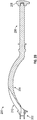
- FIGS. 2A and 2B show an impaction handle 200 in accordance with at least one example of the present disclosure.
- the impaction handle 200 can include a connection tip 202, a shaft 204, a grip 206, and an impact head 208.
- the shaft 204 of the impaction handle 200 can extend from a first end to a second end and can be curved.
- the curved profile of the shaft 204 can facilitate orienting the implant during a procedure.
- the curved profile of the shaft 204 can facilitate inserting a hemispherical cup into an acetabulum of a hip joint.
- the curved profile of the shaft 204 can allow the surgeon to position the hemispherical cup from a horizontal angle without having to reposition the patient or other instruments within the surgical environment.
- the shaft 204 can include a through hole 210 located proximate the first end of the shaft 204. As discussed below with regards to FIGS. 6A-6C , the through hole 210 can allow a driver 504 to pass through a portion of the shaft 204 and the connection tip 202.
- the shaft 204 can be manufactured from metals, polymers, ceramics, or any combination thereof.
- the shaft 204 can be manufactured using a variety of techniques including, but not limited to, machining, injection molding, casting, etc., or any combination thereof.
- the grip 206 can allow a surgeon to grip the impaction handle 200.
- the grip 206 can be contoured for an ergonomic feel.
- the grip 206 can be manufactured from metals, polymers, ceramics, or any combination thereof.
- the grip 206 can be manufactured using a variety of techniques including, but not limited to, machining, injection molding, overmolding, casting, etc., or any combination thereof
- the impact head 208 can be located at the second end of the shaft 204 and can be a continuation of the shaft 204 or the grip 206.
- the impact head 208 can provide a location for a surgeon to strike the impaction handle 200 during a surgery to seat an implant.
- the impact head 208 can be manufactured from metals, polymers, ceramics, or any combination thereof.
- the impact head 208 can be manufactured from a variety of techniques including, but not limited to, machining, injection molding, casting, etc., or any combination thereof.
- FIGS. 3A and 3B show an alternative impaction handle 300 in accordance with at least one example of the present disclosure.
- the impaction handle 300 can include the connection tip 202, a shaft 304, a grip 306, and an impact head 308.
- the shaft 304 of the impaction handle 300 can extend from a first end to a second end and can be straight.
- the straight profile of the shaft 304 can facilitate orienting the implant during a procedure. For example, during a hip replacement, the straight profile of the shaft 304 can facilitate inserting a hemispherical cup into an acetabulum of a hip joint.
- a straight impaction handle such as impaction handle 300 can provide a surgeon with greater leverage and minimize deflections when the impact head 308 is struck with a mallet.
- the shaft 304 can include a through hole 310 that can extend from the connection tip 202 to the impact head 308. As discussed below with regards to FIGS. 6A-6C , the through hole 310 can allow a threaded rod to pass through the shaft 304, the grip 306, and at least a portion of the impact head 308.
- the shaft 304 can be manufactured from metals, polymers, ceramics, or any combination thereof.
- the shaft 304 can be manufactured using a variety of techniques including, but not limited to, machining, injection molding, casting, etc., or any combination thereof.
- the grip 306 can allow a surgeon to grip the impaction handle 300.
- the grip 306 can be contoured for an ergonomic feel.
- the grip 306 can be manufactured from metals, polymers, ceramics, or any combination thereof.
- the grip 306 can be manufactured using a variety of techniques including, but not limited to, machining, injection molding, overmolding, casting, etc., or any combination thereof.
- the impact head 308 can be located at the second end of the shaft 304.
- the impact head 308 can provide a location for a surgeon to strike the impaction handle 300 during a surgery to seat an implant.
- the impact head 308 can rotate about a centerline of the through hole 310. As discussed below with regard to FIGS. 6A-6C , rotation of the impact head 308 can cause the first sliding member 104 and the second sliding member 106 to travel from the interior position to the first and second exterior positions, respectively.
- the impact head 308 can be manufactured from metals, polymers, ceramics, or any combination thereof.
- the impact head 308 can be manufactured using a variety of techniques including, but not limited to, machining, injection molding, casting, etc., or any combination thereof.
- FIGS. 4A-4C show an example of the connection tip 202.
- the connection tip can include a tip portion 402 and a translatable member 404 located at a distal end of the connection tip 202.
- the tip portion 402 can include a plurality of protrusions 406 that extend from a circular portion of the connection tip 202.
- the protrusions 406 can be of different sizes and spaced such that the protrusions 406 line up with the notches 118 defined in the impaction tip 100. During use, the protrusions 406 can pass through the notches 118 and the impaction tip 100 can be rotated about a centerline 410 of the connection tip 202.
- the rotation of the impaction tip 100 can cause the protrusions 406 to rest upon lugs 144 defined by the body 102 of the impaction tip 100.
- the lugs 144 can include depressions or other features to secure the impaction tip 100 to the connection tip 202.
- a recess defined by the lugs 144 can be slightly smaller than the protrusions 406 such that friction between the protrusions 406 and the surfaces of the lugs 144 and the body 102 hinder movement of the impaction tip 100.
- the connection tip 202 can include a bolt 408.
- the head of the bolt 408 can rest against a surface 410 of the connection tip 202 and the threaded portion of the bolt 408 can pass through the connection tip 202.
- the threaded portion of the bolt 408 can engage the translatable member 404 such that rotation of the bolt 406 can cause the translatable member 404 to travel along the centerline 410.
- rotation of the bolt 408 in a clockwise direction can cause the translatable member 404 to travel towards an opening 412 of the connection tip 202. All or a portion of the translatable member 404 can fit into the opening 412.
- the translatable member 404 can have a wedge or conical shape. During use, and as shown in FIG. 6C , as the translatable member 404 is moved towards the connection tip 202, exterior surfaces of the translatable member 404 can contact the first sliding member 104 and the second sliding member 106. Due to the wedge or conical shape of the translatable member 404, the contact between the exterior surface of the translatable member 404 and the first sliding member 104 and the second sliding member 106 can cause the first sliding member 104 and the second sliding member 106 to slide from the interior position to the first and second exterior positions as described herein. For example, the translatable member 404 can have a polished exterior surface to reduce friction between the translatable member 404 and the first sliding member 104 and the second sliding member 106.
- the first curved surface 126 and the second curved surface 128 can contact an interior surface of an implant.
- the contact between the first curved surface 126, the second curved surface 128, and the implant can cause the impaction tip 100 to hold the implant via a surface friction force.
- the translatable member 404 wedges between the first sliding member 104 and the second sliding member 106 causing the first curved surface 126 and the second curved surface 128 to grip the implant.
- the first curved surface 126 and the second curved surface 128 can deform to conform to the surface of the implant.
- FIG. 4A shows the bolt 408 can be accessed via the through hole 210 of the impaction handle 200
- a threaded rod can pass through the straight impaction handle 300.
- the threaded rod can be connected to the impact head 308 such that rotation of the impact head 308 causes the threaded rod to rotate.
- the threaded rod can be connected directly to the impact head 308 or can be a bolt that passes through the impact head 308.
- the impact head 308 can include a hexagonal recess that can receive a head of a long bolt that passes through the impact head 308, the shaft 304, and into or through the connection tip 202.
- connection tip 202 can be a continuation of the shaft 204 or 304.
- the shaft 204 can be made of surgical grade stainless steel and during the manufacturing process of the shaft 204 to connection tip 202 can be milled using a CNC machine at the same time the shaft 204 is formed.
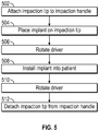
- FIG. 5 shows a flowchart for a method 500 of attaching and detaching an implant to the impaction tip 100.
- the method 500 is being described with reference to the impaction tip 100, the impaction handles 200 and 300, the connection tip 202, the impact heads 208 and 308, and other components described herein merely for purposes of example.
- the method 500 is not limited to the particular components mentioned in discussing FIG. 5 or particular structures thereof.
- FIG. 5 will be discussed in conjunction with FIGS. 6A-6C to illustrate the method 500.
- the method 500 can begin at stage 502 where the impaction tip 100 is connected to the impaction handle 200 or 300.
- the impaction tip 100 can connect to the impaction handle 200 or 300 via the connection tip 202.
- the protrusions 406 can pass through the opening 116 and the notches 118. Rotation of the impaction tip 100 relative to the impaction handle 200 or 300 can secure the impaction tip 100 to the connection tip 202.
- the impaction tip 100 can be selected from a plurality of impaction tips.
- the impaction tip 100 can be included in a system of surgical components and the surgeon can select the appropriate impaction tip for a given implant.
- the surgeon may select an impaction tip having a diameter of 44 mm for use with a hemispherical cup having an inside diameter of 50 mm.
- FIG. 6A shows impaction handle 300, impaction handle 200 could be used in place of impaction handle 300.
- the method 500 can proceed to stage 504 where an implant 602 can be placed on the impaction tip 100.
- the implant facing surface 114 can be placed in contact with the implant 602.
- the method 500 can proceed to stage 506 where a driver 604 can be rotated.
- the driver 604 can be rotated in a clockwise or counterclockwise direction as indicated by arrows 606. While FIG. 6B shows the impaction handle 200, the impaction handle 300 could be used in place of the impaction handle 200.
- a straight handle may be needed for a given surgical procedure and after connecting the impaction tip 100 to the impaction handle 300 and placing the implant 602 on the impaction tip 100, the impact head 308 can be rotated as indicated by arrows 608 as shown in FIG. 6A and as disclosed herein.
- FIG. 6C shows the effect of rotation of the driver 604 or the impact head 308.
- FIG. 6C will be described in terms of rotating the driver 604.
- rotation of the driver 604 can cause the translatable member 404 to travel towards the connection tip 202 as indicated by arrow 610.
- the first sliding member 104 and the second sliding member 106 can travel in a direction transverse to the movement direction of the translatable member 404 as indicated by arrows 612 and 614, respectively.
- the first sliding member 104 and the second sliding member 106 travel, they can contact an inner surface of the implant 602 as disclosed herein.
- the surfaces of the impaction tip 100 that contact the implant can be made of a deformable material such that the contact does not damage the implant.
- the first curved surface 126, the second curved surface 128, and the implant facing surface 114 that contact the implant 602 can be made of a polymer that will deform so as to not scratch, dent, bend, or otherwise alter the implant 602 or a surface finish of the implant 602.
- the method 500 can proceed to stage 508 where the implant 602 can be installed in the patient.
- the implant 602 can be installed in an acetabulum of a patent. If needed, the surgeon can strike the impact head 208 or 308 with a mallet to seat the implant 602.
- stage 506 the method 500 can proceed to stage 510 where the driver 606 can be rotated.
- the driver 606 can be rotated clockwise in stage 506 to attach the implant 602 to the impaction tip 100, the driver 606 can be rotated counterclockwise in stage 510 to release the implant 602 from the impaction tip 100.
- stage 510 the method 500 can proceed to stage 512 where the impaction tip 100 can be detached from the impaction handle 200 or 300. Removing the impaction tip 100 from the impaction handle 200 or 300 can allow for the impaction tip 100, impaction handles 200 and 300 to be cleaned and sterilized for reuse with other patients.
Landscapes
- Health & Medical Sciences (AREA)
- Transplantation (AREA)
- Orthopedic Medicine & Surgery (AREA)
- Heart & Thoracic Surgery (AREA)
- Cardiology (AREA)
- Oral & Maxillofacial Surgery (AREA)
- Engineering & Computer Science (AREA)
- Biomedical Technology (AREA)
- Physical Education & Sports Medicine (AREA)
- Vascular Medicine (AREA)
- Life Sciences & Earth Sciences (AREA)
- Animal Behavior & Ethology (AREA)
- General Health & Medical Sciences (AREA)
- Public Health (AREA)
- Veterinary Medicine (AREA)
- Prostheses (AREA)
Claims (15)
- Impaktionsspitze (100) zur Verwendung beim Installieren eines Implantats (602), wobei die Impaktionsspitze (100) umfasst:einen Körper (102), der eine einem Griff zugewandte Oberfläche (112) und eine dem Implantat zugewandte Oberfläche (114) aufweist, wobei der Körper (102) einen gerillten Abschnitt (124), eine erste Seitenwand (120) und eine zweite Seitenwand (122) definiert, wobei die dem Griff zugewandte Oberfläche (112) eine Öffnung (116) definiert, die so bemessen ist, dass sie einen Abschnitt eines Impaktionsgriffs (200,300) aufnimmt;ein Gleitelement (104), das zumindest teilweise innerhalb des gerillten Abschnitts (124) angeordnet ist und von einer Innenposition zu einer Außenposition gleitbar ist, wobei, wenn sich das Gleitelement (104) in der Außenposition befindet, ein Abschnitt (126) des Gleitelements (104) das Implantat (602) berührt, dadurch gekennzeichnet, dass die dem Implantat zugewandte Oberfläche (114) ein gekrümmtes Profil aufweist, das so geformt ist, dass ein erster Abschnitt der dem Implantat zugewandten Oberfläche (114), der nahe der ersten Seitenwand (120) angeordnet ist, näher an der dem Griff zugewandten Oberfläche (112) angeordnet ist als ein zweiter Abschnitt der dem Implantat zugewandten Oberfläche (114), der nahe einer zweiten Seitenwand (122) angeordnet ist, um einem gekrümmten Profil des Implantats (602) zu entsprechen.
- Impaktionsspitze nach Anspruch 1, wobei der Abschnitt des Gleitelements (104), der das Implantat (602) berührt, eine gekrümmte Oberfläche (126, 128) umfasst, die geformt ist, um zu einer inneren gekrümmten Oberfläche des Implantats (602) zu passen.
- Impaktionsspitze nach Anspruch 1 oder Anspruch 2, wobei der Körper (102) einen Vorsprung (130) umfasst, der sich von einer inneren Seitenwand (132) erstreckt, und das Gleitelement (104) eine Aussparung (134) definiert, die so bemessen ist, dass sie den Vorsprung (130) aufnimmt.
- Impaktionsspitze nach Anspruch 3, wobei der Vorsprung (130) einen Kanal (136) definiert, der so bemessen ist, dass ein Abschnitt (138) des Gleitelements (104) durch den Kanal (136) hindurchtreten kann.
- Impaktionsspitze nach einem oder einer Kombination der Ansprüche 1 bis 4, ferner umfassend einen Haltestift (108, 110), der so bemessen ist, dass er durch ein durch den Körper (102) definiertes Haltestiftloch (140, 142) hindurchtritt und den Abschnitt (138) des Gleitelements (104) innerhalb des gerillten Abschnitts (124) hält.
- Impaktionsspitze nach einem oder einer Kombination der Ansprüche 1 bis 5, wobei die Öffnung (116), die durch die dem Griff zugewandte Oberfläche (112) definiert ist, eine Kerbe (118) umfasst, die so bemessen ist, dass sie einen Vorsprung (406) aufnimmt, der sich von einer Verbindungsspitze (202) eines Impaktionsgriffs (200,300) erstreckt, wobei die Kerbe (118) und der Vorsprung (406) konfiguriert sind, um die Impaktionsspitze (100) und den Impaktionsgriff (200,300) zusammenzufügen.
- Impaktionsspitze nach Anspruch 5, ferner umfassend den Impaktionsgriff (200, 300), der mit der Impaktionsspitze (100) an der dem Griff zugewandten Oberfläche (112) verbunden ist, wobei der Impaktionsgriff (200, 300) ein verschiebbares Element (404) umfasst, das zwischen dem Gleitelement (104) und einem Abschnitt des Körpers (102) angeordnet ist und konfiguriert ist, um zu bewirken, dass das Gleitelement (104) von der Innenposition zur Außenposition gleitet.
- Impaktionsspitze nach einem oder einer Kombination der Ansprüche 1 bis 7, ferner umfassend ein zweites Gleitelement (106), das zumindest teilweise innerhalb des gerillten Abschnitts (124) angeordnet ist und von der Innenposition zu einer zweiten Außenposition so gleitbar ist, dass ein Abschnitt (128) des zweiten Gleitelements (106) das Implantat berührt.
- Impaktionsspitze nach einem oder einer Kombination der Ansprüche 1 bis 8 in Kombination mit einem Impaktionsgriff (200, 300), wobei der Impaktionsgriff umfasst:eine Welle (204, 304), die sich von einem ersten Ende zu einem zweiten Ende erstreckt;einen Aufprallkopf (208, 308), der am ersten Ende angeordnet ist;undeine Verbindungsspitze (202), die am zweiten Ende angeordnet ist, und ein Abschnitt der Verbindungsspitze, der so bemessen ist, dass er durch die durch die Impaktionsspitze (100) definierte Öffnung (116) hindurchtritt, wobei die Verbindungsspitze (202) ein Durchgangsloch (210) definiert, der so bemessen ist, dass ein Treiber (604) durch mindestens ein Abschnitt der Verbindungsspitze (202) hindurchtreten kann, wobei das verschiebbare Element (404) an einem distalen Ende der Verbindungsspitze (202) angeordnet ist, wobei die Drehung des Treibers (604) in einer ersten Richtung bewirkt, dass sich das verschiebbare Element (404) in Richtung der Verbindungsspitze (202) bewegt, und eine Drehung des Treibers (604) in einer zweiten Richtung bewirkt, dass sich das verschiebbare Element (404) von der Verbindungsspitze (202) weg bewegt.
- Kombination nach Anspruch 9, wobei das verschiebbare Element (404) eine Keilform mit einem schmalen Ende nahe dem distalen Ende der Verbindungsspitze (202) aufweist, wobei das schmale Ende so bemessen ist, dass es in das durch die Verbindungsspitze (202) definierte Durchgangsloch (210) gelangt.
- Kombination nach einem oder einer Kombination der Ansprüche 9 und 10, wobei die Verbindungsspitze (202) einen Vorsprung (406) umfasst, der sich von einem kreisförmigen Abschnitt der Verbindungsspitze (202) erstreckt, wobei der Vorsprung (406) konfiguriert ist, um mit der Kerbe (118) zusammenzupassen, die durch eine Impaktionsspitze (100) definiert ist.
- Kombination nach Anspruch 9, wobei das verschiebbare Element (404) konfiguriert ist, um zu bewirken, dass die Gleitelemente (104) der Impaktionsspitze (100) eine Komponente eines Implantats (602) greifen.
- Kombination nach einem oder einer Kombination der Ansprüche 9 bis 12, wobei die Welle (204, 304) gerade ist.
- Kombination nach Anspruch 13, wobei der Treiber (604) innerhalb der Welle (304) angeordnet und mit dem Aufprallkopf (308) so verbunden ist, dass eine Drehung des Aufprallkopfes (308) eine Drehung des Treibers (604) und eine Bewegung des verschiebbaren Elements (404) bewirkt.
- Kombination nach einem oder einer Kombination der Ansprüche 9 bis 12, wobei die Welle (204, 304) gekrümmt ist.
Applications Claiming Priority (2)
| Application Number | Priority Date | Filing Date | Title |
|---|---|---|---|
| US201562147228P | 2015-04-14 | 2015-04-14 | |
| PCT/US2016/027426 WO2016168399A2 (en) | 2015-04-14 | 2016-04-14 | Implant holder |
Publications (2)
| Publication Number | Publication Date |
|---|---|
| EP3291771A2 EP3291771A2 (de) | 2018-03-14 |
| EP3291771B1 true EP3291771B1 (de) | 2021-02-17 |
Family
ID=55953386
Family Applications (1)
| Application Number | Title | Priority Date | Filing Date |
|---|---|---|---|
| EP16721554.0A Active EP3291771B1 (de) | 2015-04-14 | 2016-04-14 | Implantathalter |
Country Status (3)
| Country | Link |
|---|---|
| US (1) | US10842648B2 (de) |
| EP (1) | EP3291771B1 (de) |
| WO (1) | WO2016168399A2 (de) |
Families Citing this family (1)
| Publication number | Priority date | Publication date | Assignee | Title |
|---|---|---|---|---|
| EP3291771B1 (de) | 2015-04-14 | 2021-02-17 | Biomet Manufacturing, LLC | Implantathalter |
Family Cites Families (7)
| Publication number | Priority date | Publication date | Assignee | Title |
|---|---|---|---|---|
| US5098437A (en) * | 1991-02-13 | 1992-03-24 | Pfizer Hospital Products Group, Inc. | Acetabular cup positioning insert |
| FR2850010B1 (fr) * | 2003-01-17 | 2005-12-02 | Tornier Sa | Ancillaire de pose d'un cotyle prothetique pour une prothese de hanche |
| GB0617484D0 (en) * | 2006-09-05 | 2006-10-18 | Comis Orthopaedics Ltd | Surgical apparatus |
| GB0702945D0 (en) * | 2007-02-15 | 2007-03-28 | Depuy Ireland Ltd | An instrument for gripping a cup component of a joint prosthesis |
| FR2929103B1 (fr) * | 2008-03-26 | 2010-04-02 | Scor Group | Prothese cotyloidienne du type dit "a double mobilite" |
| EP2572679B1 (de) * | 2011-09-23 | 2015-07-15 | Greatbatch Medical SA | Halter für keramisches Implantat |
| EP3291771B1 (de) | 2015-04-14 | 2021-02-17 | Biomet Manufacturing, LLC | Implantathalter |
-
2016
- 2016-04-14 EP EP16721554.0A patent/EP3291771B1/de active Active
- 2016-04-14 US US15/557,204 patent/US10842648B2/en active Active
- 2016-04-14 WO PCT/US2016/027426 patent/WO2016168399A2/en not_active Ceased
Non-Patent Citations (1)
| Title |
|---|
| None * |
Also Published As
| Publication number | Publication date |
|---|---|
| US20180049893A1 (en) | 2018-02-22 |
| WO2016168399A3 (en) | 2016-11-24 |
| US10842648B2 (en) | 2020-11-24 |
| EP3291771A2 (de) | 2018-03-14 |
| WO2016168399A2 (en) | 2016-10-20 |
Similar Documents
| Publication | Publication Date | Title |
|---|---|---|
| US10398569B2 (en) | Impactor-extractor | |
| US7727282B2 (en) | Method and apparatus for implanting a prosthesis | |
| EP2082705B1 (de) | Einsetzgerät für Sicherungsring | |
| EP2953586B1 (de) | Vorrichtung zur positionierung einer prothese | |
| US8409288B2 (en) | Transforaminal intersomatic cage for an intervertebral fusion graft and an instrument for implanting the cage | |
| US11938032B2 (en) | Prosthetic implant removal tool and associated method | |
| EP2712558B1 (de) | Orthopädisches Instrument für Hüftgelenkschirurgie | |
| US8323284B2 (en) | Adapter driver for orthopaedic reamer | |
| JPH08510945A (ja) | 寛骨臼カップ位置決め工具、及び寛骨臼カップ位置決め方法 | |
| BR112018073530B1 (pt) | Sistema de instrumento cirúrgico ortopédico | |
| EP4069155B1 (de) | Entfernbare neigungsführung für ein implantat-einsetzungswerkzeug | |
| US20160100957A1 (en) | Acetabular explant apparatus, system, and method | |
| WO2009098491A1 (en) | Medical device and method | |
| EP3986306B1 (de) | Distales radioulnargelenkprothesensystem | |
| US20180235774A1 (en) | System for implanting a prosthesis | |
| EP3291771B1 (de) | Implantathalter | |
| EP3111897B1 (de) | Orthopädische einschlagvorrichtung | |
| US20240325161A1 (en) | Systems and methods for knee arthroplasty | |
| WO2014108540A1 (en) | Cap for use with acetabular cup |
Legal Events
| Date | Code | Title | Description |
|---|---|---|---|
| STAA | Information on the status of an ep patent application or granted ep patent |
Free format text: STATUS: THE INTERNATIONAL PUBLICATION HAS BEEN MADE |
|
| PUAI | Public reference made under article 153(3) epc to a published international application that has entered the european phase |
Free format text: ORIGINAL CODE: 0009012 |
|
| STAA | Information on the status of an ep patent application or granted ep patent |
Free format text: STATUS: REQUEST FOR EXAMINATION WAS MADE |
|
| 17P | Request for examination filed |
Effective date: 20171114 |
|
| AK | Designated contracting states |
Kind code of ref document: A2 Designated state(s): AL AT BE BG CH CY CZ DE DK EE ES FI FR GB GR HR HU IE IS IT LI LT LU LV MC MK MT NL NO PL PT RO RS SE SI SK SM TR |
|
| AX | Request for extension of the european patent |
Extension state: BA ME |
|
| DAV | Request for validation of the european patent (deleted) | ||
| DAX | Request for extension of the european patent (deleted) | ||
| STAA | Information on the status of an ep patent application or granted ep patent |
Free format text: STATUS: EXAMINATION IS IN PROGRESS |
|
| 17Q | First examination report despatched |
Effective date: 20190628 |
|
| GRAP | Despatch of communication of intention to grant a patent |
Free format text: ORIGINAL CODE: EPIDOSNIGR1 |
|
| STAA | Information on the status of an ep patent application or granted ep patent |
Free format text: STATUS: GRANT OF PATENT IS INTENDED |
|
| INTG | Intention to grant announced |
Effective date: 20200825 |
|
| RIN1 | Information on inventor provided before grant (corrected) |
Inventor name: CLAVEL, SEBASTIEN Inventor name: BREVET, NICOLAS Inventor name: VIZIER, JEAN-MICHEL |
|
| GRAS | Grant fee paid |
Free format text: ORIGINAL CODE: EPIDOSNIGR3 |
|
| GRAA | (expected) grant |
Free format text: ORIGINAL CODE: 0009210 |
|
| STAA | Information on the status of an ep patent application or granted ep patent |
Free format text: STATUS: THE PATENT HAS BEEN GRANTED |
|
| AK | Designated contracting states |
Kind code of ref document: B1 Designated state(s): AL AT BE BG CH CY CZ DE DK EE ES FI FR GB GR HR HU IE IS IT LI LT LU LV MC MK MT NL NO PL PT RO RS SE SI SK SM TR |
|
| REG | Reference to a national code |
Ref country code: GB Ref legal event code: FG4D |
|
| REG | Reference to a national code |
Ref country code: CH Ref legal event code: NV Representative=s name: MICHELI AND CIE SA, CH Ref country code: CH Ref legal event code: EP |
|
| REG | Reference to a national code |
Ref country code: DE Ref legal event code: R096 Ref document number: 602016052536 Country of ref document: DE |
|
| REG | Reference to a national code |
Ref country code: AT Ref legal event code: REF Ref document number: 1360474 Country of ref document: AT Kind code of ref document: T Effective date: 20210315 |
|
| REG | Reference to a national code |
Ref country code: IE Ref legal event code: FG4D |
|
| REG | Reference to a national code |
Ref country code: LT Ref legal event code: MG9D |
|
| REG | Reference to a national code |
Ref country code: NL Ref legal event code: MP Effective date: 20210217 |
|
| PG25 | Lapsed in a contracting state [announced via postgrant information from national office to epo] |
Ref country code: FI Free format text: LAPSE BECAUSE OF FAILURE TO SUBMIT A TRANSLATION OF THE DESCRIPTION OR TO PAY THE FEE WITHIN THE PRESCRIBED TIME-LIMIT Effective date: 20210217 Ref country code: GR Free format text: LAPSE BECAUSE OF FAILURE TO SUBMIT A TRANSLATION OF THE DESCRIPTION OR TO PAY THE FEE WITHIN THE PRESCRIBED TIME-LIMIT Effective date: 20210518 Ref country code: HR Free format text: LAPSE BECAUSE OF FAILURE TO SUBMIT A TRANSLATION OF THE DESCRIPTION OR TO PAY THE FEE WITHIN THE PRESCRIBED TIME-LIMIT Effective date: 20210217 Ref country code: PT Free format text: LAPSE BECAUSE OF FAILURE TO SUBMIT A TRANSLATION OF THE DESCRIPTION OR TO PAY THE FEE WITHIN THE PRESCRIBED TIME-LIMIT Effective date: 20210617 Ref country code: NO Free format text: LAPSE BECAUSE OF FAILURE TO SUBMIT A TRANSLATION OF THE DESCRIPTION OR TO PAY THE FEE WITHIN THE PRESCRIBED TIME-LIMIT Effective date: 20210517 Ref country code: LT Free format text: LAPSE BECAUSE OF FAILURE TO SUBMIT A TRANSLATION OF THE DESCRIPTION OR TO PAY THE FEE WITHIN THE PRESCRIBED TIME-LIMIT Effective date: 20210217 Ref country code: BG Free format text: LAPSE BECAUSE OF FAILURE TO SUBMIT A TRANSLATION OF THE DESCRIPTION OR TO PAY THE FEE WITHIN THE PRESCRIBED TIME-LIMIT Effective date: 20210517 |
|
| REG | Reference to a national code |
Ref country code: AT Ref legal event code: MK05 Ref document number: 1360474 Country of ref document: AT Kind code of ref document: T Effective date: 20210217 |
|
| PG25 | Lapsed in a contracting state [announced via postgrant information from national office to epo] |
Ref country code: SE Free format text: LAPSE BECAUSE OF FAILURE TO SUBMIT A TRANSLATION OF THE DESCRIPTION OR TO PAY THE FEE WITHIN THE PRESCRIBED TIME-LIMIT Effective date: 20210217 Ref country code: NL Free format text: LAPSE BECAUSE OF FAILURE TO SUBMIT A TRANSLATION OF THE DESCRIPTION OR TO PAY THE FEE WITHIN THE PRESCRIBED TIME-LIMIT Effective date: 20210217 Ref country code: LV Free format text: LAPSE BECAUSE OF FAILURE TO SUBMIT A TRANSLATION OF THE DESCRIPTION OR TO PAY THE FEE WITHIN THE PRESCRIBED TIME-LIMIT Effective date: 20210217 Ref country code: PL Free format text: LAPSE BECAUSE OF FAILURE TO SUBMIT A TRANSLATION OF THE DESCRIPTION OR TO PAY THE FEE WITHIN THE PRESCRIBED TIME-LIMIT Effective date: 20210217 Ref country code: RS Free format text: LAPSE BECAUSE OF FAILURE TO SUBMIT A TRANSLATION OF THE DESCRIPTION OR TO PAY THE FEE WITHIN THE PRESCRIBED TIME-LIMIT Effective date: 20210217 |
|
| PG25 | Lapsed in a contracting state [announced via postgrant information from national office to epo] |
Ref country code: IS Free format text: LAPSE BECAUSE OF FAILURE TO SUBMIT A TRANSLATION OF THE DESCRIPTION OR TO PAY THE FEE WITHIN THE PRESCRIBED TIME-LIMIT Effective date: 20210617 |
|
| PG25 | Lapsed in a contracting state [announced via postgrant information from national office to epo] |
Ref country code: SM Free format text: LAPSE BECAUSE OF FAILURE TO SUBMIT A TRANSLATION OF THE DESCRIPTION OR TO PAY THE FEE WITHIN THE PRESCRIBED TIME-LIMIT Effective date: 20210217 Ref country code: AT Free format text: LAPSE BECAUSE OF FAILURE TO SUBMIT A TRANSLATION OF THE DESCRIPTION OR TO PAY THE FEE WITHIN THE PRESCRIBED TIME-LIMIT Effective date: 20210217 Ref country code: EE Free format text: LAPSE BECAUSE OF FAILURE TO SUBMIT A TRANSLATION OF THE DESCRIPTION OR TO PAY THE FEE WITHIN THE PRESCRIBED TIME-LIMIT Effective date: 20210217 Ref country code: CZ Free format text: LAPSE BECAUSE OF FAILURE TO SUBMIT A TRANSLATION OF THE DESCRIPTION OR TO PAY THE FEE WITHIN THE PRESCRIBED TIME-LIMIT Effective date: 20210217 |
|
| REG | Reference to a national code |
Ref country code: DE Ref legal event code: R097 Ref document number: 602016052536 Country of ref document: DE |
|
| PG25 | Lapsed in a contracting state [announced via postgrant information from national office to epo] |
Ref country code: SK Free format text: LAPSE BECAUSE OF FAILURE TO SUBMIT A TRANSLATION OF THE DESCRIPTION OR TO PAY THE FEE WITHIN THE PRESCRIBED TIME-LIMIT Effective date: 20210217 Ref country code: RO Free format text: LAPSE BECAUSE OF FAILURE TO SUBMIT A TRANSLATION OF THE DESCRIPTION OR TO PAY THE FEE WITHIN THE PRESCRIBED TIME-LIMIT Effective date: 20210217 Ref country code: MC Free format text: LAPSE BECAUSE OF FAILURE TO SUBMIT A TRANSLATION OF THE DESCRIPTION OR TO PAY THE FEE WITHIN THE PRESCRIBED TIME-LIMIT Effective date: 20210217 Ref country code: DK Free format text: LAPSE BECAUSE OF FAILURE TO SUBMIT A TRANSLATION OF THE DESCRIPTION OR TO PAY THE FEE WITHIN THE PRESCRIBED TIME-LIMIT Effective date: 20210217 |
|
| PLBE | No opposition filed within time limit |
Free format text: ORIGINAL CODE: 0009261 |
|
| STAA | Information on the status of an ep patent application or granted ep patent |
Free format text: STATUS: NO OPPOSITION FILED WITHIN TIME LIMIT |
|
| PG25 | Lapsed in a contracting state [announced via postgrant information from national office to epo] |
Ref country code: LU Free format text: LAPSE BECAUSE OF NON-PAYMENT OF DUE FEES Effective date: 20210414 |
|
| REG | Reference to a national code |
Ref country code: BE Ref legal event code: MM Effective date: 20210430 |
|
| 26N | No opposition filed |
Effective date: 20211118 |
|
| PG25 | Lapsed in a contracting state [announced via postgrant information from national office to epo] |
Ref country code: AL Free format text: LAPSE BECAUSE OF FAILURE TO SUBMIT A TRANSLATION OF THE DESCRIPTION OR TO PAY THE FEE WITHIN THE PRESCRIBED TIME-LIMIT Effective date: 20210217 Ref country code: ES Free format text: LAPSE BECAUSE OF FAILURE TO SUBMIT A TRANSLATION OF THE DESCRIPTION OR TO PAY THE FEE WITHIN THE PRESCRIBED TIME-LIMIT Effective date: 20210217 |
|
| PG25 | Lapsed in a contracting state [announced via postgrant information from national office to epo] |
Ref country code: SI Free format text: LAPSE BECAUSE OF FAILURE TO SUBMIT A TRANSLATION OF THE DESCRIPTION OR TO PAY THE FEE WITHIN THE PRESCRIBED TIME-LIMIT Effective date: 20210217 |
|
| PG25 | Lapsed in a contracting state [announced via postgrant information from national office to epo] |
Ref country code: IT Free format text: LAPSE BECAUSE OF FAILURE TO SUBMIT A TRANSLATION OF THE DESCRIPTION OR TO PAY THE FEE WITHIN THE PRESCRIBED TIME-LIMIT Effective date: 20210217 |
|
| PG25 | Lapsed in a contracting state [announced via postgrant information from national office to epo] |
Ref country code: IS Free format text: LAPSE BECAUSE OF FAILURE TO SUBMIT A TRANSLATION OF THE DESCRIPTION OR TO PAY THE FEE WITHIN THE PRESCRIBED TIME-LIMIT Effective date: 20210617 |
|
| PG25 | Lapsed in a contracting state [announced via postgrant information from national office to epo] |
Ref country code: BE Free format text: LAPSE BECAUSE OF NON-PAYMENT OF DUE FEES Effective date: 20210430 |
|
| PG25 | Lapsed in a contracting state [announced via postgrant information from national office to epo] |
Ref country code: HU Free format text: LAPSE BECAUSE OF FAILURE TO SUBMIT A TRANSLATION OF THE DESCRIPTION OR TO PAY THE FEE WITHIN THE PRESCRIBED TIME-LIMIT; INVALID AB INITIO Effective date: 20160414 |
|
| PG25 | Lapsed in a contracting state [announced via postgrant information from national office to epo] |
Ref country code: CY Free format text: LAPSE BECAUSE OF FAILURE TO SUBMIT A TRANSLATION OF THE DESCRIPTION OR TO PAY THE FEE WITHIN THE PRESCRIBED TIME-LIMIT Effective date: 20210217 |
|
| P01 | Opt-out of the competence of the unified patent court (upc) registered |
Effective date: 20230526 |
|
| PG25 | Lapsed in a contracting state [announced via postgrant information from national office to epo] |
Ref country code: MK Free format text: LAPSE BECAUSE OF FAILURE TO SUBMIT A TRANSLATION OF THE DESCRIPTION OR TO PAY THE FEE WITHIN THE PRESCRIBED TIME-LIMIT Effective date: 20210217 |
|
| PG25 | Lapsed in a contracting state [announced via postgrant information from national office to epo] |
Ref country code: MT Free format text: LAPSE BECAUSE OF FAILURE TO SUBMIT A TRANSLATION OF THE DESCRIPTION OR TO PAY THE FEE WITHIN THE PRESCRIBED TIME-LIMIT Effective date: 20210217 |
|
| PGFP | Annual fee paid to national office [announced via postgrant information from national office to epo] |
Ref country code: FR Payment date: 20250314 Year of fee payment: 10 |
|
| PGFP | Annual fee paid to national office [announced via postgrant information from national office to epo] |
Ref country code: DE Payment date: 20250313 Year of fee payment: 10 |
|
| PGFP | Annual fee paid to national office [announced via postgrant information from national office to epo] |
Ref country code: GB Payment date: 20250411 Year of fee payment: 10 |
|
| PGFP | Annual fee paid to national office [announced via postgrant information from national office to epo] |
Ref country code: CH Payment date: 20250501 Year of fee payment: 10 |
|
| PGFP | Annual fee paid to national office [announced via postgrant information from national office to epo] |
Ref country code: IE Payment date: 20250415 Year of fee payment: 10 |
|
| PG25 | Lapsed in a contracting state [announced via postgrant information from national office to epo] |
Ref country code: TR Free format text: LAPSE BECAUSE OF FAILURE TO SUBMIT A TRANSLATION OF THE DESCRIPTION OR TO PAY THE FEE WITHIN THE PRESCRIBED TIME-LIMIT Effective date: 20210217 |