EP3296095B1 - Dispositifs de compactage et de collecte d'ordures - Google Patents
Dispositifs de compactage et de collecte d'ordures Download PDFInfo
- Publication number
- EP3296095B1 EP3296095B1 EP17199774.5A EP17199774A EP3296095B1 EP 3296095 B1 EP3296095 B1 EP 3296095B1 EP 17199774 A EP17199774 A EP 17199774A EP 3296095 B1 EP3296095 B1 EP 3296095B1
- Authority
- EP
- European Patent Office
- Prior art keywords
- pivot
- pivot links
- pivot axis
- links
- axis
- Prior art date
- Legal status (The legal status is an assumption and is not a legal conclusion. Google has not performed a legal analysis and makes no representation as to the accuracy of the status listed.)
- Active
Links
Images


Classifications
-
- B—PERFORMING OPERATIONS; TRANSPORTING
- B30—PRESSES
- B30B—PRESSES IN GENERAL
- B30B9/00—Presses specially adapted for particular purposes
- B30B9/30—Presses specially adapted for particular purposes for baling; Compression boxes therefor
- B30B9/3042—Containers provided with, or connectable to, compactor means
- B30B9/3046—Containers with built-in compactor means
-
- B—PERFORMING OPERATIONS; TRANSPORTING
- B65—CONVEYING; PACKING; STORING; HANDLING THIN OR FILAMENTARY MATERIAL
- B65F—GATHERING OR REMOVAL OF DOMESTIC OR LIKE REFUSE
- B65F1/00—Refuse receptacles; Accessories therefor
- B65F1/10—Refuse receptacles; Accessories therefor with refuse filling means, e.g. air-locks
-
- B—PERFORMING OPERATIONS; TRANSPORTING
- B65—CONVEYING; PACKING; STORING; HANDLING THIN OR FILAMENTARY MATERIAL
- B65F—GATHERING OR REMOVAL OF DOMESTIC OR LIKE REFUSE
- B65F1/00—Refuse receptacles; Accessories therefor
- B65F1/14—Other constructional features; Accessories
- B65F1/1405—Compressing means incorporated in, or specially adapted for, refuse receptacles
-
- B—PERFORMING OPERATIONS; TRANSPORTING
- B65—CONVEYING; PACKING; STORING; HANDLING THIN OR FILAMENTARY MATERIAL
- B65F—GATHERING OR REMOVAL OF DOMESTIC OR LIKE REFUSE
- B65F1/00—Refuse receptacles; Accessories therefor
- B65F1/14—Other constructional features; Accessories
- B65F1/1426—Housings, cabinets or enclosures for refuse receptacles
- B65F1/1447—Housings, cabinets or enclosures for refuse receptacles located underground
-
- B—PERFORMING OPERATIONS; TRANSPORTING
- B65—CONVEYING; PACKING; STORING; HANDLING THIN OR FILAMENTARY MATERIAL
- B65F—GATHERING OR REMOVAL OF DOMESTIC OR LIKE REFUSE
- B65F1/00—Refuse receptacles; Accessories therefor
- B65F1/14—Other constructional features; Accessories
- B65F1/16—Lids or covers
- B65F1/1615—Lids or covers with means for locking, fastening or permanently closing thereof
-
- B—PERFORMING OPERATIONS; TRANSPORTING
- B65—CONVEYING; PACKING; STORING; HANDLING THIN OR FILAMENTARY MATERIAL
- B65F—GATHERING OR REMOVAL OF DOMESTIC OR LIKE REFUSE
- B65F2210/00—Equipment of refuse receptacles
- B65F2210/168—Sensing means
-
- B—PERFORMING OPERATIONS; TRANSPORTING
- B65—CONVEYING; PACKING; STORING; HANDLING THIN OR FILAMENTARY MATERIAL
- B65F—GATHERING OR REMOVAL OF DOMESTIC OR LIKE REFUSE
- B65F2210/00—Equipment of refuse receptacles
- B65F2210/172—Solar cells
Definitions
- the present invention relates to the field of collector and compactor devices, in particular to the field of vertical compactor devices that compact refuse collected in an exchangeable bin open at the top.
- Known vertical refuse collector and compactor devices generally comprise a housing with a refuse insertion opening. Refuse inserted through the refuse insertion opening is collected in an exchangeable bin, e.g. a wheeled bin, provided in the interior of the housing.
- Known vertical refuse collector and compactor devices further comprise a compactor unit adapted to press on the collected refuse to reduce its volume.
- the compactor unit generally comprises a press element, such as a plate, that during compaction moves from a higher position above or near the top of the bin to a lower position inside the bin, thereby pressing the collected refuse in the bin further down.
- the compactor unit furthermore generally comprises a frame attached to the housing and a hinged construction that connects the press element to the frame. Through compaction more refuse can be collected in a bin of a given size, thus reducing costs associated with emptying and/or replacing full bins.
- WO2006073224 discloses a vertical refuse collector and compactor device comprising a housing to hold an exchangeable open topped bin, said housing having a front face with a refuse insertion opening, a rear face and a top face.
- the device further includes a compactor unit comprising a frame attached to said housing and two parallel spaced apart upper pivot links.
- the upper pivot links are at one end connected to the frame at a first pivot axis, said first pivot axis being a horizontal axis near the rear face of the housing.
- the compactor unit further comprises one front pivot link connected at a second pivot axis to said upper pivot links, said second pivot axis being at the end of the upper pivot link opposite the first pivot axis and parallel to the first pivot axis.
- the compactor unit further comprises a press element, connected to said front pivot link at the end thereof opposite the second pivot axis, and two parallel lower pivot links, substantially parallel to the two upper pivot links.
- the press element is formed as two horizontal rods at right angles to each other with foldable extension rods pivotally attached to the ends of each rod.
- Said two lower pivot links are at one end connected to the frame at a third pivot axis, said third pivot axis being below the first pivot axis and parallel to the first pivot axis.
- Said two lower pivot links are connected to front pivot link at a fourth pivot axis, said fourth pivot axis being at the ends of the lower pivot links opposite the first pivot axis and parallel to the first pivot axis.
- the compactor unit further comprises an actuator adapted to impart to the press element a vertical motion from an upper retracted position, in which the upper pivot links tilt toward the top of the housing, to a lower pressing position and vice versa for compacting refuse.
- the compactor unit further comprises a motor to drive said actuator.
- Document CN 201 228 156 Y discloses a refuse collector and compactor device comprising a housing adapted to hold an exchangeable open topped bin.
- the housing has a front face with a refuse insertion opening.
- the device further comprises a compactor unit with a frame attached to the housing, upper pivot links, lower pivot links, front pivot links, and rear pivot links.
- a press element is connected to the front and rear pivot links. The press plate is actuated to move from a tilted orientation in an upper retracted position, with the edge of the press plate closest to the front face of the housing elevated with respect to the edge near the rear face of the housing, to a substantially levelled orientation in the lower pressing position.
- the object of the present invention is to provide a vertical refuse collection and compaction device that overcomes one or more of the abovementioned drawbacks.
- the present invention provides a refuse collection and compactor device in which refuse collection is not hindered by the presence of the compactor unit, while at the same time providing a compactor unit that allows to be economic of space.
- economic of space it is meant that the addition of the compactor unit within a housing adapted to hold an exchangeable open topped bin, said housing having a front face with a refuse insertion opening, requires only a limited enlargement of the housing (approximately maximally 10-20 percent of the original volume of the housing).
- the compaction unit does not require the height of the housing to be much increased compared to the height of the housing without compactor unit. This is e.g. advantageous in public areas where the device might otherwise be an undesirable obstacle.
- the present invention provides a refuse collector and compactor device-according to claim 1 and a method for collecting and compacting refuse according to claim 14.
- the distance between the fourth pivot axis and the fifth pivot axis moreover equals the distance between the seventh and the sixth pivot axis, so that the tilt of the press plate is substantially equal to the tilt of the upper pivot links.
- the hinged construction that comprises one or more upper pivot links, one or more lower pivot links, one or more front pivot links and one or more rear pivot links, interconnected and connected to the press plate as described above with the rear pivot links connected at the seventh pivot axis to said one or more lower pivot links results in a tilt of the press plate with a tilting angle with respect to the horizontal about an axis parallel to the first pivot axis.
- Said tilting angle of the press plate is in a fixed relation to the angle of the upper pivot links to the horizontal.
- the distance between the fourth pivot axis and the fifth pivot axis equals the distance between the seventh and the sixth pivot axis, so that the angle of the press plate with respect to horizontal is equal to the angle of the upper pivot links to the horizontal.
- the distance between the fourth pivot axis and the fifth pivot axis may also be smaller or larger than the distance between the seventh and the sixth pivot axis, so that the press plate is for instance tilted upwards at its front edge when the one or more upper pivot links are oriented horizontally and becomes levelled when the upper pivot links are rotated further downwards.
- the same angle of the press plate and the upper pivot links is preferred as this leads to a most economic of space compactor unit in the retracted position.
- the press plate In the pressing position the press plate is preferably substantially levelled to press upon a large part of the refuse contained in the collector unit. In the pressing position the angle between upper pivot links and front pivot links is large, e.g. 60-120 degrees.
- the upper pivot links tilt toward the top of the housing and as the lower pivot links are parallel to the upper pivot links also the lower pivot links are tilted toward the top of the housing.
- the angle between the upper pivot links and the front pivot links is small, e.g. 0-30 degrees.
- the rear pivot links are parallel to the front pivot links and are thus at the same small angle to the front pivot links.
- the front and rear pivot links are thus substantially folded against the upper and lower pivot links.
- the press plate is in the preferred embodiment tilted at the same angle as the upper pivot links and the angle between the front pivot links and the press plate is therefore small, e.g. 0-30 degrees.
- the press plate seen from the front face of the housing at least partially covers the hinged construction formed by the upper pivot links, lower pivot links, front pivot links and rear pivot links. From this viewpoint the press plate may also partially or entirely cover the actuator and motor.
- the folding of the hinged construction and the tilting of the press plate thus leads to an economic of size compactor unit in the retracted position. It also strongly reduces the chance that refuse inserted into the bin through the refuse insertion opening will get stuck on top of the press plate and/or in the hinged construction. Also, as the hinged construction may thus be hidden from view, it is unlikely that it will be tampered with.
- the vertical refuse collector and compactor device is to be used with an exchangeable bin, possibly wheeled, e.g. two wheels at one lower corner, open at the top and placed in the housing.
- an exchangeable bin possibly wheeled, e.g. two wheels at one lower corner, open at the top and placed in the housing.
- the compactor unit When the bin is empty or only partially filled the compactor unit is in the retracted position above the exchangeable bin.
- a sensor is provided in order to detect the fill level in the bin. Only when the bin is substantially filled with refuse the compactor unit moves from the retracted position to the pressing position. During the motion from the retracted position to the pressing position the press plate enters the exchangeable bin and moves downward down to a height that is preferably between 70 and 90 % of the height of the bin, thereby compacting the refuse. Subsequently the compactor moves back to the retracted position, in which it remains until the bin is substantially filled again.
- the press plate exerts a force on the refuse in order to compact the refuse. If the bin contains a lot of refuse that has already been compacted several times the compactor unit may not be able to apply the force needed to reach its most extended position with the press plate substantially levelled. When in this situation the compactor unit reaches its maximum force it will retract into the retracted position.
- the lower pivot links have a horizontal position in between a pair of parallel spaced apart upper pivot links.
- the lower pivot links comprise one or more recesses into which in the upper retracted position the fifth and sixth pivot axis insert and/or the upper pivot links comprise one or more recesses into which in the retracted position the fourth and seventh pivot axis insert.
- the hinged construction and press plate are folded together to a larger extent and thus to obtain a more economic of space arrangement in the retracted position.
- the one more rear pivot links are connected at the abovementioned seventh pivot axis to said one or more lower pivot links.
- the press plate is not an entirely flat plate, but is somewhat rounded around an axis parallel to the first axis to be able to apply a larger pressing force and/or to obtain a more economic of size retracted position.
- the angle of the press plate with respect to horizontal referred to above is the angle between horizontal and the plane through the fifth and sixth pivot axis.
- the actuator is connected at one end to the one or more lower pivot links and the one or more rear pivot links are connected at the seventh pivot axis to the one or more lower pivot links.
- the lower pivot links are used to transmit a pressing force from the actuator to the press plate, while front pivot links and upper pivot links provide stability to the hinged construction.
- the one or more rear pivot links may be rounded between their two pivot axis to be able to withstand a large pressing force. Other embodiments of the invention may distribute the forces differently over the pivot links.
- the actuator may be connected between the frame and a different part of the hinged construction, e.g. the upper pivot link or the rear pivot link, or between the frame and the press plate.
- connection means such as connection rods interconnect the pair of pivot links to add stability to the hinged construction.
- connection rods are preferably provided at ends of the upper pivot links, lower pivot links, front pivot links and rear pivot links, e.g. at the second pivot axis, the fourth pivot axis and/or the seventh pivot axis.
- the frame of the compactor unit can be connected to a side face or to the top face of the housing.
- the frame is connected to the top face of the housing towards the rear face of the housing or to the rear face of the housing towards the top face.
- the frame may comprise one or more suspension elements extending downwards from the frame, at the ends of which the one or more upper pivot links and lower pivot links are connected.
- the actuator may be a linear actuator, e.g. a cylinder-with-piston, e.g. hydraulic, or a spindle, e.g. an electric motor screw spindle.
- a linear actuator e.g. a cylinder-with-piston, e.g. hydraulic
- a spindle e.g. an electric motor screw spindle.
- the actuator may at one end be connected to the frame and at the other end connected to the one or more pivot links or directly to the press plate, preferably to the one or more lower pivot links.
- the motor is placed adjacent to and in front of the actuator, toward the front side of the housing, to achieve an economic of space retracted position.
- the housing and compactor unit are preferably used with an exchangeable bin open at the top having a volume between 120-240 litres, but the same device with minor adjustments is expected to be useable with bins of larger or smaller volume.
- the length of the pivot links and the size of the press element can be adjusted so as to achieve good compaction.
- a bin with a volume of 120 litres has an opening at its top with a standard size of approximately 38 cm by 38 cm and the press plate for a bin of this volume has in a preferred embodiment a size of approximately 32 cm by 28 cm. Smaller or slightly larger press plate sizes are however also possible.
- the refuse collector and compactor device has a refuse insertion opening into which a lid with a handle is provided.
- a lid with a handle is provided.
- the lid is pulled or rotated outward from the housing using the handle. Refuse is then inserted, after which the lid is pivoted inwards again.
- the refuse collector and compactor device comprises an active or passive locking system to prevent simultaneous opening of the lid provided into the refuse insertion opening and operation of the press mechanism.
- the locking system thus prevents the compactor unit from leaving the retracted position when the lid is open, while preventing the lid from opening when the compactor unit has started its downwards motion from the retracted to the pressing position.
- the press plate attains a tilted orientation in the retracted position with an angle upwards with respect to horizontal of between 10 and 80 degrees, preferably between 30 and 60 degrees.
- the press plate attains a substantially levelled orientation in the pressing position with a tilt upwards or downwards with respect to horizontal of between 0 and 30 degrees.
- the refuse collector and compactor device comprises a shield system that shields the assembly of links of the device, or at least a part thereof, from contact with and/or interference by the refuse.
- the shield system may be embodied to shield these elements of the device from contact with refuse at the moment that said refuse is inserted via the refuse insertion opening into a bin that is placed in the housing.
- the shield system may also shield these elements of the device from contact with said refuse during the compaction thereof, that is, during the pressing motion of the device. Such contact may arise in the absence of a shield system e.g. when during compression an item of refuse near a side of the housing is pushed on top of the press plate.
- Said shield system may comprise a front plate provided to, e.g. secured onto and/or integrated with, the one or more front pivot links, e.g. at the front side thereof, e.g. with a bottom edge of the front plate substantially at the height of the fifth pivot axis and extending along said one or more front pivot links to an upper end of the front plate.
- Said upper end may for instance be provided substantially at the height of the fourth pivot axis.
- Said front plate preferably has a front plate width in a direction parallel to the first pivot axis between a left end and a right end that is equal to the width of the press plate, said press plate width being also in a direction parallel to the first pivot axis between a left and a right end.
- Said shield system may, e.g. in addition to said front plate, comprise two press plate side plates provided to the press plate at respectively the left and right side thereof.
- Said press plate side plates preferably are raised from the respective side of the press plate, e.g. extend in a side plane perpendicular to the front face of the housing and perpendicular to the top face of the housing.
- Said shield system may also comprise two front side shield plates that are joined to the front plate at the respectively the left and right end thereof.
- Said front side shield plates generally extend in a side plane, e.g. substantially perpendicular to the front face of the housing and perpendicular to the top face of the housing.
- the front plate shields the linkage assembly of the collector and compactor device from refuse at the front side of said device
- said side plates shield these elements from refuse at the sides.
- the fifth pivot axis is preferably provided at or near the front edge of the press plate.
- said shield system also comprises a bottom shield plate provided to said one or more front pivot links at a bottom end thereof. Said bottom plate extends along the lower end of the front pivot links from the front thereof substantially to the fifth pivot axis In this way said bottom plate adjoins with its front end to the lower end of the front plate and adjoins with its rear end to the front edge of the press plate.
- a plate member of the shield system may be formed by a closed surface plate, e.g. of steel, but may also be made of perforated plate material when desired or other non-closed surface members, e.g. a grating.
- the present invention also relates to a combination of a refuse collector and compactor device according to the present invention and an exchangeable bin, e.g. arranged within the housing.
- the present invention also relates to a method for collecting and compacting refuse, wherein use is made of a refuse collector and compactor device according to the present invention and wherein an exchangeable bin is arranged within the housing.
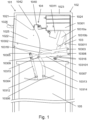
- the refuse collector and compactor device 101 comprises a housing 102 with a front face 1021, a top face 1023 and a rear face 1024.
- the front face 1021 has a refuse insertion opening 1022 into which a lid 1025 with a handle 1026 is provided.
- An open topped bin 105 is provided in the housing 102.
- the compactor unit 103 comprises a frame 10301 attached to said housing 102.
- the frame may comprise one or more suspension elements 103011, here two spaced apart parallel suspension elements, extending mainly downwards.
- the compactor unit furthermore comprises a pair of parallel spaced apart upper pivot links 10302, each connected at one end to one of the suspension elements 103011 at a first pivot axis 10303.
- the first pivot axis 10303 is a horizontal axis near the rear face of the housing.
- the compactor unit further comprises a pair of parallel spaced apart front pivot links 10304, each connected to one upper pivot link 10302 at a second pivot axis 10305 provided at the end of the upper pivot link 10302 opposite the first pivot axis 10303.
- the second pivot axis 10305 is parallel to the first axis 10303.
- the compactor unit further comprises a rectangular or square press plate 10306 connected at a fifth axis 10312 to the pair of front pivot links 10304.
- the fifth axis is parallel to the first axis.
- the compactor unit further comprises a pair of parallel spaced apart lower pivot links 10307 parallel to the pair of upper pivot links 10302.
- Each lower pivot link is connected to one of the suspension elements at a third pivot axis 10308 provided below the first pivot axis 10303.
- the third pivot axis 10308 is parallel to the first pivot axis 10303.
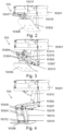
- the lower pivot links may have a horizontal position within the pair of upper pivot links as shown most clearly in figures 3-4 .
- Each lower pivot link 10307 is connected at its end opposite the third pivot axis 10308 to one of the front pivot links 10304 at a fourth axis 10309.
- the fourth axis 10309 is provided on the front pivot link 10304 between the second axis 10305 and the fifth axis 10312.
- the fourth axis 10309 is parallel to the first axis 10303.
- the compactor unit 103 further comprises a pair of parallel spaced apart rear pivot links 10313, each connected at one end to one of the lower pivot links 10307 at a seventh axis 10315 provided on each of said lower pivot links 10307 between the fourth axis 10309 and the third axis 10308.
- the seventh axis 10315 is parallel to the first axis 10303.
- Each rear pivot link 10313 is connected at its end opposite the seventh axis 10315 to the press plate at a sixth axis 10314.
- the sixth axis 10314 is parallel to the first axis 10303.
- the compactor unit 103 further comprises a cylinder-with-piston 10310 comprising a cylinder 10310a and a piston 10310b.
- the cylinder 10310a is connected to the frame 10301, while the piston 10310b is connected at an axis 103101 on the lower pivot links 10307 at a position thereof between the seventh axis 10315 and the third axis 10308.
- the axis 103101 is parallel to the first axis 10303.
- the compactor unit 103 further comprises a motor 10311 to drive said actuator.
- the motor 10311 is connected to the frame 10301 and provided in front of the cylinder 10310a.
- the press plate 10306 and the hinged construction formed by the upper pivot links 10302, lower pivot links 10307, front pivot links 10304 and rear pivot links 10313, are shown in figure 9 in substantially the pressing position with the hinged construction at an extension close to the maximum extension it is adapted to attain and with the press plate 10306 substantially levelled.
- the upper pivot links 10302 and the lower pivot links 10307 contain recesses 10316 into which in the retracted position the pivotal connections at the fourth 10309, fifth 10312, sixth 10314 and seventh 10315 pivot axis insert.
- the rear pivot links 10313 have a curved shape along the longitudinal direction.
- Connection rods 10317 interconnect the pair of parallel upper pivot links and the pair of front pivot links at the second pivot axis 10305, the pair of parallel lower pivot links and the pair of front pivot links at the fourth pivot axis 10309 and the pair of parallel lower pivot links and the pair of rear pivot links at the seventh pivot axis 10315.
- Figure 2 shows the compactor unit in the retracted position.
- the upper pivot links 10302 are tilted toward the top of the housing and the angle between upper pivot links and front pivot links is small, e.g. approximately 10 degrees.
- the press plate is tilted at an angle with respect to the horizontal that is substantially the same as the angle of the upper pivot links with respect to the horizontal.
- the piston 10310b is also retracted.
- the distance between the fourth pivot axis 10309 and the fifth pivot axis 10312 equals the distance between the seventh 10315 and the sixth pivot 10314 axis, so that the angle of the press plate with respect to horizontal equals the angle of the upper pivot links to the horizontal.
- the upper pivot links 10302 and the lower pivot links 10307 are substantially levelled, while the front pivot links 10304 and rear pivot links 10313 extend substantially in the vertical direction.
- the press plate 10306 is substantially parallel to the upper pivot links 10302 and lower pivot links 10307 and thus also substantially levelled.
- the piston 10310b of the cylinder-with-piston 10310 is at its maximum extension.
- the lid 1025 provided in the front face 1021 of the housing 102 comprises a front face 10251 at the position of the refuse insertion opening 1022 and two side faces 10252.
- the lid 1025 is pulled or rotated outwards from the housing using the handle 1026. Refuse is then inserted, after which the lid 1025 is pushed inwards again.
- the passive locking system 104 comprises a cap 1040 that partially covers in the retracted position the upper ends of the one or more upper pivot links and front pivot links at the site of the second pivot axis 10305.
- the cap 1040 covers the upper pivot links and front pivot links at the site of the second pivot axis at the top and sides.
- the cap 1040 comprises a front face 1042, into which recesses 1041, shown in figure 15, are provided at the outer ends.
- the side faces 10252 of the lid 1025 can partly insert into said recesses 1041.
- the cap 1040 When the lid 1025 is closed the cap 1040 is located above the lid and is not in contact with the lid 1040 as shown in figure 5 .
- the side faces of the lid 10252 move forward and partly insert into the recesses 1041 in the front face 1042 of the cap as shown in figure 6 .
- the downward motion of the pressing unit requires the upper pivot links 10302 to perform a rotation that in the initial stage of this downward movement moves the upper end of the upper pivot links near the second pivot axis 10305 toward the front face 1021 of the housing 102.
- the cap 1040 surrounding the upper pivot links 10302 should therefore move forward together with the pivot links, e.g. by a pivotable and/or extendable connection of the cap 1040 to the frame 10301.
- the compactor unit can start its movement from the storage to the pressing position by pushing the cap 1040 that surrounds the upper end of the upper pivot links closer toward the front face 1021 of the housing 102.
- the cap 1040 prevents further outward movement of the lid 1025 from being opened when the compactor unit is not in the storage position.
- the shield system serves as a mechanical shield that prevents refuse from reaching the assembly of links and related pivots of the device, e.g. as someone deposits refuse into the device via the opening thereof.
- the shield system enhances the operational reliability of the device.
- the shield system 106 comprises a front plate 1061 that is provided to the pair of spaced apart parallel front pivot links 10304, here provided to the front side of the pair of spaced apart parallel front pivot links 10304. Said front plate 1061 here interconnects the pair of front pivot links 10304.
- the front plate 1061 extends laterally over a width substantially equal to the width of the press plate.
- the width of both the front plate 1061 and the press plate here correspond to a dimension parallel to the first pivot axis 10303.
- the press plate and front plate each extend along said direction parallel to the first pivot axis 10303 between a left end and a right end.
- the front plate 1061 has a bottom end that is provided substantially at the height of the fifth pivot axis 10312 and extends along said one or more front pivot links 10304 to an upper end, e.g. said upper end being substantially at the height of the fourth pivot axis 10309. Said front 1061 thus extends along at least a portion of the front pivot links 10304, and possibly extends along the full length of the front pivot links 10304 between the height of the second pivot axis 10305 and the height of the fifth pivot axis 10312.
- the shield system 106 moreover comprises side plates 1062 provided to the left end and the right end of the press plate. Said side plates 1062 here each extend in a side plane perpendicular to the front face of the housing and perpendicular to the top face of the housing.
- front plate 1061 is joined to front side shield plates 1063 which are provided to the left end and the right end of the front plate.
- front side shield plates 1063 here each extend in a side plane perpendicular to the front face of the housing and perpendicular to the top face of the housing.
- the front side shield plates 1063 are here provided at the extreme left and right end of said front plate 1061, while the press plate side plates 1062, while also provided substantially at the left and right end of said press plate 10306, are provided slightly inwards with respect to the front side shield plates 1063, so that front side shield plate 1063 and press plate side plate 1062 are slightly offset, thereby allowing these adjacent press plate side plates 1062 and front side shield plates 1063 to overlap when viewed from the side. Said overlap avoids a gap between said shielding plates from arising in the retracted position, in the pressing position or in any position intermediate these position.
- the fifth pivot axis 10312 is provided at the edge of the press plate 10306 that is closest to the front face of the housing.
- the shield system 106 may also comprise a bottom plate 1064 that serves to avoid the occurrence of a gap between the front plate 1061 and the press plate 10306.
- Said bottom plate 1064 is provided to said one or more front pivot links 10304 at a bottom end thereof and extends along the lower end of the front pivot links 10304 from the front thereof substantially to the fifth pivot axis 10312. In this way the bottom plate 1064 adjoins with its front end to the lower end of the front plate 1061 and adjoins with its rear end to the front edge of the press plate 10306.
- the front plate 1061 and bottom plate 1064, optionally also the front plate side plates 1063, may be joined to form an integral structure.
- the press plate 10306 comprises a rearmost section of which the tilt is, as in previous embodiments, equal to the tilt of the upper pivot links 10302.
- the press plate 10306 moreover comprises a section forward of said rearmost section with a slightly more downward orientation, followed by a section having a more upward orientation. Said sections allow for a more compact collector and compactor device in the retracted position.
- the overall tilt of the press plate 10306 in the embodiment of figures 8-10 is however still substantially equal to the tilt of the upper pivot links 10302.
Landscapes
- Engineering & Computer Science (AREA)
- Mechanical Engineering (AREA)
- Refuse Collection And Transfer (AREA)
- Refuse-Collection Vehicles (AREA)
Claims (14)
- Dispositif de compactage et de collecte d'ordures (101) comprenant :un logement (102) pour contenir un compartiment à partie supérieure ouverte échangeable (105), ledit logement ayant une face avant (1021) avec une ouverture d'insertion d'ordures (1022), une face arrière (1024) et une face supérieure (1023),une unité de compactage (103) comprenant :- un bâti (10301) fixé sur ledit logement (102),- une ou plusieurs liaisons de pivot supérieures (10302), lesdites une ou plusieurs liaisons de pivot supérieures étant raccordées, au niveau d'une extrémité, au bâti à un premier axe de pivot (10303), ledit premier axe de pivot étant un axe horizontal à proximité de la face arrière du logement,- une ou plusieurs liaisons de pivot avant (10304), lesdites une ou plusieurs liaisons de pivot avant étant raccordées à un deuxième axe de pivot (10305), auxdites une ou plusieurs liaisons de pivot supérieures (10302), ledit deuxième axe de pivot étant à l'extrémité de la liaison de pivot supérieure, opposé au premier axe de pivot et parallèle au premier axe de pivot,- un élément de presse (10306) raccordé auxdites une ou plusieurs liaisons de pivot avant au niveau de ses extrémités opposées au deuxième axe de pivot,- une ou plusieurs liaisons de pivot inférieures (10307) sensiblement parallèles aux une ou plusieurs liaisons de pivot supérieures, lesdites une ou plusieurs liaisons de pivot inférieures étant raccordées, au niveau d'une extrémité, au bâti à un troisième axe de pivot (10308), ledit troisième axe de pivot étant au-dessous du premier axe de pivot et parallèle au premier axe de pivot, lesdites une ou plusieurs liaisons de pivot inférieures étant raccordées aux une ou plusieurs liaisons de pivot avant à un quatrième axe de pivot (10309), ledit quatrième axe de pivot étant à l'extrémité de la liaison de pivot inférieure opposée au premier axe de pivot et parallèle au premier axe de pivot,- un actionneur (10310) adapté pour communiquer à l'élément de presse, un mouvement vertical allant d'une position rétractée supérieure, dans laquelle les liaisons de pivot supérieures s'inclinent vers le dessus du logement, jusqu'à une position de pression inférieure et vice versa pour compacter les ordures,dans lequel l'élément de presse est une plaque de presse (10306) raccordée aux liaisons de pivot avant à un cinquième axe de pivot (10312), ledit cinquième axe de pivot étant parallèle au premier axe de pivot,dans lequel l'unité de compactage comprend en outre une ou plusieurs liaisons de pivot arrière (10313), sensiblement parallèles aux liaisons de pivot avant, lesdites une ou plusieurs liaisons de pivot arrière étant raccordées, au niveau d'une extrémité, à ladite plaque de presse à un sixième axe de pivot (10314), ledit sixième axe de pivot étant parallèle au premier axe de pivot et décalé vers la face arrière du logement par rapport au cinquième axe de pivot, lesdites une ou plusieurs liaisons de pivot arrière étant raccordées à un septième axe de pivot (10315) auxdites une ou plusieurs liaisons de pivot inférieures, ledit septième axe étant au niveau de l'extrémité de la liaison de pivot arrière opposé au sixième axe de pivot et parallèle au premier axe de pivot, lesdites une ou plusieurs liaisons de pivot arrière étant adaptées pour communiquer à la plaque de presse un mouvement à partir d'une orientation inclinée dans la position rétractée supérieure, avec le bord de la plaque de presse (10306) le plus proche de la face avant du logement levé par rapport au bord à proximité de la face arrière du logement, jusqu'à une orientation sensiblement de niveau dans la position de pression inférieure, caractérisé en ce que l'unité de compactage (103) comprend un moteur (10311) pour entraîner ledit actionneur, eten ce que lesdites liaisons de pivot inférieures comprennent un ou plusieurs évidements dans lesquels, dans la position rétractée supérieure, les cinquième et sixième axes de pivot s'insèrent, et/ouen ce que lesdites liaisons de pivot supérieures (10302) comprennent un ou plusieurs évidements dans lesquels, dans la position rétractée, le quatrième (10309) et le septième (10315) axe de pivot s'insèrent.
- Dispositif de compactage d'ordures selon la revendication 1, dans lequel la distance entre le quatrième axe de pivot et le cinquième axe de pivot est égale à la distance entre le septième et le sixième axe de pivot, de sorte que l'inclinaison de la plaque de presse est sensiblement égale à l'inclinaison des liaisons de pivot supérieures.
- Dispositif de compactage et de collecte d'ordures selon la revendication 1 ou 2, dans lequel les liaisons de pivot supérieures (10307) ont une position horizontale entre une paire de liaisons de pivot supérieures (10302) parallèles espacées.
- Dispositif de compactage et de collecte d'ordures selon l'une quelconque des revendications précédentes, dans lequel au moins l'une, par exemple toutes, parmi les liaisons de pivot supérieures, les liaisons de pivot avant, les liaisons de pivot inférieures et les liaisons de pivot arrière est une paire de liaisons de pivot parallèles espacées.
- Dispositif de compactage et de collecte d'ordures selon la revendication 4, dans lequel les liaisons de pivot supérieures, les liaisons de pivot avant, les liaisons de pivot inférieures et les liaisons de pivot arrière sont une paire de liaisons de pivot parallèles espacées et une ou plusieurs des paires de liaisons de pivot supérieures, de liaisons de pivot inférieures, de liaisons de pivot avant et de liaisons de pivot arrière sont interconnectées par un moyen de raccordement, par exemple des tiges de raccordement, de préférence placées au niveau du deuxième axe de pivot, du quatrième axe de pivot et/ou du septième axe de pivot.
- Dispositif de compactage et de collecte d'ordures selon l'une quelconque des revendications précédentes, dans lequel ladite plaque de presse (10306) a une largeur de plaque de presse dans une direction parallèle au premier axe de pivot entre une extrémité gauche et une extrémité droite de ladite plaque de presse et dans lequel ledit dispositif de compactage et de collecte d'ordures comprend en outre un système de protection (106) comprenant une plaque avant (1061), dans lequel ladite plaque avant est prévue sur lesdites une ou plusieurs liaisons de pivot avant (10304), par exemple prévue sur lesdites une ou plusieurs liaisons de pivot avant au niveau de son côté avant, dans lequel la plaque avant a une largeur de plaque avant dans une direction sensiblement parallèle au premier axe de pivot (10303) entre une extrémité gauche et une extrémité droite de ladite plaque avant qui est de préférence sensiblement égale à la largeur de plaque de presse, dans lequel ladite plaque avant a une extrémité inférieure sensiblement à la hauteur du cinquième axe de pivot et s'étend le long desdites une ou plusieurs liaisons de pivot avant jusqu'à une extrémité supérieure, par exemple ladite extrémité supérieure étant sensiblement à la hauteur du quatrième axe de pivot.
- Dispositif de compactage et de collecte d'ordures selon la revendication 6, dans lequel le système de protection comprend en outre deux plaques latérales de plaque de presse (1062) prévues sur la plaque de presse respectivement au niveau de son côté gauche et droit, chaque plaque latérale de plaque de presse s'étendant de préférence dans un plan latéral perpendiculaire à la face avant du logement et perpendiculaire à la face supérieure du logement, et dans lequel le système de protection comprend en outre deux plaques de protection du côté avant (1063) assemblées à la plaque avant au niveau de ou respectivement à côté de son extrémité gauche et droite, chaque plaque de protection du côté avant s'étendant de préférence dans un plan latéral perpendiculaire à la face avant et perpendiculaire à la face supérieure du logement.
- Dispositif de compactage et de collecte d'ordures selon la revendication 6 ou 7, dans lequel ledit cinquième axe de pivot est prévu sensiblement au niveau du bord avant de la plaque de presse et dans lequel le système de protection comprend en outre une plaque inférieure (1064), ladite plaque inférieure étant prévue sur lesdites une ou plusieurs liaisons de pivot avant au niveau de son extrémité inférieure et s'étendant le long de l'extrémité inférieure des liaisons de pivot avant à partir de sa partie avant sensiblement jusqu'au cinquième axe de pivot, de sorte que ladite plaque inférieure est attenante avec son extrémité avant, à l'extrémité inférieure de la plaque avant et est attenante avec son extrémité arrière, au bord avant de la plaque de presse.
- Dispositif de compactage et de collecte d'ordures selon l'une quelconque des revendications précédentes, dans lequel l'actionneur est un actionneur linéaire, de préférence un cylindre avec un piston (10310), au niveau d'une extrémité, raccordé au bâti et au niveau de l'autre extrémité, raccordé aux une ou plusieurs liaisons de pivot ou directement à la plaque de presse (10306), de préférence aux une ou plusieurs liaisons de pivot inférieures, dans lequel facultativement le moteur (10311) est placé de manière adjacente à l'actionneur linéaire et vers la face avant du logement.
- Dispositif de compactage et de collecte d'ordures selon l'une quelconque des revendications précédentes, comprenant en outre un couvercle (1025) prévu dans l'ouverture d'insertion d'ordures et un système de verrouillage passif (104) qui empêche l'ouverture du couvercle lorsque l'unité de compactage n'est pas dans la position rétractée, dans lequel facultativement ledit système de verrouillage passif empêche également le mouvement de l'unité de compactage lorsque le couvercle est ouvert.
- Dispositif de compactage et de collecte d'ordures selon l'une quelconque des revendications précédentes, dans lequel la plaque de presse (10306) atteint une orientation inclinée dans la position rétractée avec un angle ascendant par rapport à l'horizontale compris entre 10 et 80 degrés, de préférence entre 30 et 60 degrés.
- Dispositif de compactage et de collecte d'ordures selon l'une quelconque des revendications précédentes, dans lequel la plaque de presse (10306) atteint une orientation sensiblement de niveau dans la position de pression avec une inclinaison vers le haut ou vers le bas par rapport à l'horizontale comprise entre 0 et 30 degrés.
- En combinaison, un dispositif de compactage et de collecte d'ordures (101) selon l'une quelconque des revendications précédentes et un compartiment échangeable (105), par exemple agencé à l'intérieur du logement.
- Procédé pour compacter et collecter des ordures, dans lequel on utilise un dispositif de compactage et de collecte d'ordures selon l'une quelconque des revendications précédentes, et dans lequel un compartiment échangeable (105) est agencé à l'intérieur du logement.
Applications Claiming Priority (4)
| Application Number | Priority Date | Filing Date | Title |
|---|---|---|---|
| NL2014400A NL2014400B1 (en) | 2015-03-05 | 2015-03-05 | Top loading refuse distributing and compacting device and refuse collection system. |
| NL2014644A NL2014644B1 (en) | 2015-04-15 | 2015-04-15 | Vertical refuse collector and compactor device. |
| PCT/NL2016/050148 WO2016140573A1 (fr) | 2015-03-05 | 2016-03-03 | Dispositifs de compactage et de collecte d'ordures |
| EP16722405.4A EP3265303B1 (fr) | 2015-03-05 | 2016-03-03 | Dispositifs de compactage et de collecte d'ordures |
Related Parent Applications (2)
| Application Number | Title | Priority Date | Filing Date |
|---|---|---|---|
| EP16722405.4A Division-Into EP3265303B1 (fr) | 2015-03-05 | 2016-03-03 | Dispositifs de compactage et de collecte d'ordures |
| EP16722405.4A Division EP3265303B1 (fr) | 2015-03-05 | 2016-03-03 | Dispositifs de compactage et de collecte d'ordures |
Publications (3)
| Publication Number | Publication Date |
|---|---|
| EP3296095A1 EP3296095A1 (fr) | 2018-03-21 |
| EP3296095C0 EP3296095C0 (fr) | 2023-06-28 |
| EP3296095B1 true EP3296095B1 (fr) | 2023-06-28 |
Family
ID=55967380
Family Applications (2)
| Application Number | Title | Priority Date | Filing Date |
|---|---|---|---|
| EP16722405.4A Active EP3265303B1 (fr) | 2015-03-05 | 2016-03-03 | Dispositifs de compactage et de collecte d'ordures |
| EP17199774.5A Active EP3296095B1 (fr) | 2015-03-05 | 2016-03-03 | Dispositifs de compactage et de collecte d'ordures |
Family Applications Before (1)
| Application Number | Title | Priority Date | Filing Date |
|---|---|---|---|
| EP16722405.4A Active EP3265303B1 (fr) | 2015-03-05 | 2016-03-03 | Dispositifs de compactage et de collecte d'ordures |
Country Status (4)
| Country | Link |
|---|---|
| EP (2) | EP3265303B1 (fr) |
| DK (1) | DK3265303T3 (fr) |
| ES (1) | ES2734707T3 (fr) |
| WO (1) | WO2016140573A1 (fr) |
Families Citing this family (12)
| Publication number | Priority date | Publication date | Assignee | Title |
|---|---|---|---|---|
| FI128175B (fi) | 2018-03-22 | 2019-11-29 | Lehtovuori Oy | Puristin ja rakenne, joka käsittää puristimen |
| NL2020951B1 (en) | 2018-05-17 | 2019-11-25 | Mr Fill Holding B V | A refuse collector and compactor system |
| AU2019226177B2 (en) * | 2018-09-06 | 2025-07-10 | Melbourne City Council | Compactor for a rubbish bin |
| GR1009826B (el) * | 2019-02-06 | 2020-09-25 | Αδελφοι Βουρλουμη Α.Ε.Β.Ε. | Συστημα διαχειρισης ωφελιμου ογκου μεσω συμπιεσης σε υπογειοποιημενους ή μη καδους συλλογης απορριμματων |
| NL2023535B1 (en) | 2019-07-19 | 2021-02-08 | Mr Fill Holding B V | Refuse handling device and drive assembly thereof |
| NL2023538B1 (en) * | 2019-07-19 | 2021-02-08 | Mr Fill Holding B V | Refuse distribution and compaction device |
| WO2021013555A1 (fr) | 2019-07-19 | 2021-01-28 | Mr. Fill Holding B.V. | Dispositifs et procédés de répartition et de compactage des déchets |
| NL1043377B1 (nl) | 2019-09-16 | 2021-05-17 | De Rooij Milieutechniek B V | Ondergrondse afvalcontainer |
| CN111591629B (zh) * | 2020-06-16 | 2024-12-31 | 永昊环境科技(集团)有限公司 | 一种地埋式分类垃圾箱 |
| NL2030570B1 (en) | 2022-01-17 | 2023-07-27 | Mr Fill Holding B V | Refuse collection system and control unit therefor |
| EP4466207A1 (fr) | 2022-01-17 | 2024-11-27 | Mr. Fill Holding B.V. | Système de collecte de déchets, son unité de commande et procédé |
| NL2037234B1 (en) | 2024-03-12 | 2025-09-26 | Mr Fill Holding B V | Refuse collection system and method |
Citations (5)
| Publication number | Priority date | Publication date | Assignee | Title |
|---|---|---|---|---|
| NL7900279A (nl) * | 1979-01-12 | 1980-03-31 | Smit Bernardus Johannes | Werkwijze en inrichting tot het verdichten van afval. |
| NL1000419C2 (en) * | 1995-05-23 | 1996-11-25 | Ecovision B V | Collecting system for selected refuse |
| EP1508535A1 (fr) * | 2003-08-20 | 2005-02-23 | Bruno Perlini | Dispositif de ramassage d'ordures triées |
| DE102006031131A1 (de) * | 2005-07-04 | 2007-03-01 | Rimetaal B.V. | Vorrichtung und Verfahren für das Einsammeln und Zusammenpressen von Abfall |
| CH704762A1 (de) * | 2011-03-31 | 2012-10-15 | System Alpenluft Ag | Entsorgungsvorrichtung. |
Family Cites Families (17)
| Publication number | Priority date | Publication date | Assignee | Title |
|---|---|---|---|---|
| DE2202156C3 (de) * | 1972-01-18 | 1980-01-10 | Fichtel & Sachs Ag, 8720 Schweinfurt | Haushaltmüllpresse mit geradegeführtem Hebelmechanismus zur Stempelbewegung |
| CH564467A5 (en) | 1973-04-06 | 1975-07-31 | Ochsner & Cie Ag J | Equipment for filling and compressing garbage - has arrangement for alternately opening feeder and compressing garbage |
| GB1477311A (en) * | 1974-06-03 | 1977-06-22 | Shelvoke Drewry Ltd | Vertical compactor |
| JPH09136191A (ja) * | 1995-11-10 | 1997-05-27 | Sanyo Electric Co Ltd | ごみ圧縮機 |
| NL1006782C2 (nl) | 1997-08-15 | 1999-02-16 | Bammens Bv | Systeem en werkwijze voor het ophalen van afval dat in een ondergrondse container is opgeslagen. |
| NL1010751C2 (nl) | 1998-12-07 | 2000-06-19 | Bammens Bv | Systeem, vrachtautomobiel en verzamelhouder voor het verzamelen van huishoudelijk afval. |
| DE29922397U1 (de) | 1999-12-20 | 2000-03-30 | H & G Entsorgungssysteme GmbH, 57299 Burbach | Müllcontainereinrichtung |
| US6588330B1 (en) | 2000-05-15 | 2003-07-08 | Michael Importico | Trash compactor system |
| NL1015528C1 (nl) | 2000-06-26 | 2001-12-28 | Bammens Bv | Inrichting voor het bewaren van afvalmateriaal. |
| KR100516850B1 (ko) | 2005-01-04 | 2005-09-27 | 김철호 | 자동 개폐식 쓰레기통 |
| DE202006016421U1 (de) | 2006-10-26 | 2007-03-01 | Ecovision B.V. | Unterflurmüllsammelbehälter |
| CN201228156Y (zh) * | 2008-06-02 | 2009-04-29 | 北京印刷学院 | 具有压实机构的垃圾箱 |
| NL2006618C2 (nl) | 2011-04-18 | 2012-10-22 | Keywaste B V | Persinrichting. |
| NL2008505C2 (nl) | 2012-03-19 | 2013-09-23 | Beheermij Engels Tilburg B V | Inrichting voor het ondergronds verzamelen van afval alsmede werkwijze voor het toepassen van een dergelijke inrichting. |
| NL1039541C2 (nl) | 2012-04-16 | 2013-10-28 | Rhino Engineering B V | Huisvuilcontainer en inbouweenheid daarvoor. |
| DE202012004707U1 (de) | 2012-04-23 | 2012-07-02 | H & G Entsorgungssysteme Gmbh | Müllsammelbehälter |
| DE202014101191U1 (de) | 2014-03-17 | 2014-04-17 | H & G Entsorgungssysteme Gmbh | Behälter zum Aufnehmen von Müll und Abfallsammelbehälter |
-
2016
- 2016-03-03 EP EP16722405.4A patent/EP3265303B1/fr active Active
- 2016-03-03 EP EP17199774.5A patent/EP3296095B1/fr active Active
- 2016-03-03 WO PCT/NL2016/050148 patent/WO2016140573A1/fr not_active Ceased
- 2016-03-03 ES ES16722405T patent/ES2734707T3/es active Active
- 2016-03-03 DK DK16722405.4T patent/DK3265303T3/da active
Patent Citations (5)
| Publication number | Priority date | Publication date | Assignee | Title |
|---|---|---|---|---|
| NL7900279A (nl) * | 1979-01-12 | 1980-03-31 | Smit Bernardus Johannes | Werkwijze en inrichting tot het verdichten van afval. |
| NL1000419C2 (en) * | 1995-05-23 | 1996-11-25 | Ecovision B V | Collecting system for selected refuse |
| EP1508535A1 (fr) * | 2003-08-20 | 2005-02-23 | Bruno Perlini | Dispositif de ramassage d'ordures triées |
| DE102006031131A1 (de) * | 2005-07-04 | 2007-03-01 | Rimetaal B.V. | Vorrichtung und Verfahren für das Einsammeln und Zusammenpressen von Abfall |
| CH704762A1 (de) * | 2011-03-31 | 2012-10-15 | System Alpenluft Ag | Entsorgungsvorrichtung. |
Also Published As
| Publication number | Publication date |
|---|---|
| EP3265303B1 (fr) | 2019-05-08 |
| DK3265303T3 (da) | 2019-07-29 |
| EP3296095C0 (fr) | 2023-06-28 |
| EP3296095A1 (fr) | 2018-03-21 |
| WO2016140573A1 (fr) | 2016-09-09 |
| EP3265303A1 (fr) | 2018-01-10 |
| ES2734707T3 (es) | 2019-12-11 |
Similar Documents
| Publication | Publication Date | Title |
|---|---|---|
| EP3296095A1 (fr) | Dispositifs de compactage et de collecte d'ordures | |
| US20110038697A1 (en) | Side loading refuse collection system | |
| CA2891919C (fr) | Benne pour vehicule de collecte de dechets avec compaction amelioree | |
| CN208560500U (zh) | 垃圾车上料机构及垃圾车 | |
| NL1035561C2 (nl) | Hefmechanisme en beladingssysteem voor het ledigen van containers, een vuilnisauto en werkwijze daarvoor. | |
| US20220267087A1 (en) | Refuse distribution and compaction devices and methods | |
| EP1745921A1 (fr) | Structure d'un compacteur de déchets pour un usage domestique | |
| US4406573A (en) | Device for loading and compacting rubbish in a fixed or mobile receptacle | |
| DE4005968C2 (de) | Müllsammelfahrzeug | |
| US7997852B1 (en) | Side loader garbage truck | |
| US11136188B2 (en) | Waste collection vehicle with raised and sloped hopper | |
| EP2530033A1 (fr) | Dispositif de préhension, de levage et de vidange des récipients à ordures | |
| DE4237143C2 (de) | Verdichtungsvorrichtung für einen Müllbehälter | |
| NL2014644B1 (en) | Vertical refuse collector and compactor device. | |
| CN210192472U (zh) | 垃圾车 | |
| DE202009009365U1 (de) | Schüttvorrichtung für ein Entsorgungsfahrzeug | |
| EP3750702A1 (fr) | Récipient doté d'une unité de compression | |
| US20060045681A1 (en) | Refuse cart lifter with an improved range of rotation | |
| CA2825719C (fr) | Vehicule de collecte de dechets a tremie soulevee et inclinee | |
| EP3415305B1 (fr) | Unité de presse à déchets stationnaire à relier à un conteneur d'échange mobile | |
| CN207293200U (zh) | 垃圾箱及垃圾车 | |
| GB2167036A (en) | Refuse loading apparatus | |
| DE4315412C2 (de) | Hub-Kippvorrichtung eines Müllsammelfahrzeuges | |
| JPS5832121B2 (ja) | 塵芥収集車の塵芥押込装置 | |
| WO2004001138A1 (fr) | Balayeuse de chaussee autopropulsee, compacte a basculement eleve |
Legal Events
| Date | Code | Title | Description |
|---|---|---|---|
| PUAI | Public reference made under article 153(3) epc to a published international application that has entered the european phase |
Free format text: ORIGINAL CODE: 0009012 |
|
| STAA | Information on the status of an ep patent application or granted ep patent |
Free format text: STATUS: THE APPLICATION HAS BEEN PUBLISHED |
|
| AC | Divisional application: reference to earlier application |
Ref document number: 3265303 Country of ref document: EP Kind code of ref document: P |
|
| AK | Designated contracting states |
Kind code of ref document: A1 Designated state(s): AL AT BE BG CH CY CZ DE DK EE ES FI FR GB GR HR HU IE IS IT LI LT LU LV MC MK MT NL NO PL PT RO RS SE SI SK SM TR |
|
| AX | Request for extension of the european patent |
Extension state: BA ME |
|
| RAP1 | Party data changed (applicant data changed or rights of an application transferred) |
Owner name: VERSCHOOR METAALTECHNIEK B.V. |
|
| RAP1 | Party data changed (applicant data changed or rights of an application transferred) |
Owner name: C.G. VERSCHOOR BEHEER B.V. |
|
| STAA | Information on the status of an ep patent application or granted ep patent |
Free format text: STATUS: REQUEST FOR EXAMINATION WAS MADE |
|
| 17P | Request for examination filed |
Effective date: 20180921 |
|
| RBV | Designated contracting states (corrected) |
Designated state(s): AL AT BE BG CH CY CZ DE DK EE ES FI FR GB GR HR HU IE IS IT LI LT LU LV MC MK MT NL NO PL PT RO RS SE SI SK SM TR |
|
| RAP1 | Party data changed (applicant data changed or rights of an application transferred) |
Owner name: MR. FILL HOLDING B.V. |
|
| GRAP | Despatch of communication of intention to grant a patent |
Free format text: ORIGINAL CODE: EPIDOSNIGR1 |
|
| STAA | Information on the status of an ep patent application or granted ep patent |
Free format text: STATUS: GRANT OF PATENT IS INTENDED |
|
| INTG | Intention to grant announced |
Effective date: 20210917 |
|
| GRAJ | Information related to disapproval of communication of intention to grant by the applicant or resumption of examination proceedings by the epo deleted |
Free format text: ORIGINAL CODE: EPIDOSDIGR1 |
|
| STAA | Information on the status of an ep patent application or granted ep patent |
Free format text: STATUS: REQUEST FOR EXAMINATION WAS MADE |
|
| INTC | Intention to grant announced (deleted) | ||
| GRAP | Despatch of communication of intention to grant a patent |
Free format text: ORIGINAL CODE: EPIDOSNIGR1 |
|
| STAA | Information on the status of an ep patent application or granted ep patent |
Free format text: STATUS: GRANT OF PATENT IS INTENDED |
|
| INTG | Intention to grant announced |
Effective date: 20220223 |
|
| GRAJ | Information related to disapproval of communication of intention to grant by the applicant or resumption of examination proceedings by the epo deleted |
Free format text: ORIGINAL CODE: EPIDOSDIGR1 |
|
| STAA | Information on the status of an ep patent application or granted ep patent |
Free format text: STATUS: REQUEST FOR EXAMINATION WAS MADE |
|
| INTC | Intention to grant announced (deleted) | ||
| GRAP | Despatch of communication of intention to grant a patent |
Free format text: ORIGINAL CODE: EPIDOSNIGR1 |
|
| STAA | Information on the status of an ep patent application or granted ep patent |
Free format text: STATUS: GRANT OF PATENT IS INTENDED |
|
| INTG | Intention to grant announced |
Effective date: 20220802 |
|
| GRAJ | Information related to disapproval of communication of intention to grant by the applicant or resumption of examination proceedings by the epo deleted |
Free format text: ORIGINAL CODE: EPIDOSDIGR1 |
|
| STAA | Information on the status of an ep patent application or granted ep patent |
Free format text: STATUS: REQUEST FOR EXAMINATION WAS MADE |
|
| INTC | Intention to grant announced (deleted) | ||
| GRAP | Despatch of communication of intention to grant a patent |
Free format text: ORIGINAL CODE: EPIDOSNIGR1 |
|
| STAA | Information on the status of an ep patent application or granted ep patent |
Free format text: STATUS: GRANT OF PATENT IS INTENDED |
|
| INTG | Intention to grant announced |
Effective date: 20230127 |
|
| GRAS | Grant fee paid |
Free format text: ORIGINAL CODE: EPIDOSNIGR3 |
|
| GRAA | (expected) grant |
Free format text: ORIGINAL CODE: 0009210 |
|
| STAA | Information on the status of an ep patent application or granted ep patent |
Free format text: STATUS: THE PATENT HAS BEEN GRANTED |
|
| AC | Divisional application: reference to earlier application |
Ref document number: 3265303 Country of ref document: EP Kind code of ref document: P |
|
| AK | Designated contracting states |
Kind code of ref document: B1 Designated state(s): AL AT BE BG CH CY CZ DE DK EE ES FI FR GB GR HR HU IE IS IT LI LT LU LV MC MK MT NL NO PL PT RO RS SE SI SK SM TR |
|
| RAP3 | Party data changed (applicant data changed or rights of an application transferred) |
Owner name: MR. FILL HOLDING B.V. |
|
| REG | Reference to a national code |
Ref country code: CH Ref legal event code: EP |
|
| REG | Reference to a national code |
Ref country code: AT Ref legal event code: REF Ref document number: 1582352 Country of ref document: AT Kind code of ref document: T Effective date: 20230715 |
|
| REG | Reference to a national code |
Ref country code: IE Ref legal event code: FG4D |
|
| REG | Reference to a national code |
Ref country code: DE Ref legal event code: R096 Ref document number: 602016080731 Country of ref document: DE |
|
| U01 | Request for unitary effect filed |
Effective date: 20230724 |
|
| U07 | Unitary effect registered |
Designated state(s): AT BE BG DE DK EE FI FR IT LT LU LV MT NL PT SE SI Effective date: 20230728 |
|
| REG | Reference to a national code |
Ref country code: LT Ref legal event code: MG9D |
|
| PG25 | Lapsed in a contracting state [announced via postgrant information from national office to epo] |
Ref country code: NO Free format text: LAPSE BECAUSE OF FAILURE TO SUBMIT A TRANSLATION OF THE DESCRIPTION OR TO PAY THE FEE WITHIN THE PRESCRIBED TIME-LIMIT Effective date: 20230928 |
|
| PG25 | Lapsed in a contracting state [announced via postgrant information from national office to epo] |
Ref country code: RS Free format text: LAPSE BECAUSE OF FAILURE TO SUBMIT A TRANSLATION OF THE DESCRIPTION OR TO PAY THE FEE WITHIN THE PRESCRIBED TIME-LIMIT Effective date: 20230628 Ref country code: HR Free format text: LAPSE BECAUSE OF FAILURE TO SUBMIT A TRANSLATION OF THE DESCRIPTION OR TO PAY THE FEE WITHIN THE PRESCRIBED TIME-LIMIT Effective date: 20230628 Ref country code: GR Free format text: LAPSE BECAUSE OF FAILURE TO SUBMIT A TRANSLATION OF THE DESCRIPTION OR TO PAY THE FEE WITHIN THE PRESCRIBED TIME-LIMIT Effective date: 20230929 |
|
| PG25 | Lapsed in a contracting state [announced via postgrant information from national office to epo] |
Ref country code: SK Free format text: LAPSE BECAUSE OF FAILURE TO SUBMIT A TRANSLATION OF THE DESCRIPTION OR TO PAY THE FEE WITHIN THE PRESCRIBED TIME-LIMIT Effective date: 20230628 |
|
| PG25 | Lapsed in a contracting state [announced via postgrant information from national office to epo] |
Ref country code: ES Free format text: LAPSE BECAUSE OF FAILURE TO SUBMIT A TRANSLATION OF THE DESCRIPTION OR TO PAY THE FEE WITHIN THE PRESCRIBED TIME-LIMIT Effective date: 20230628 |
|
| PG25 | Lapsed in a contracting state [announced via postgrant information from national office to epo] |
Ref country code: IS Free format text: LAPSE BECAUSE OF FAILURE TO SUBMIT A TRANSLATION OF THE DESCRIPTION OR TO PAY THE FEE WITHIN THE PRESCRIBED TIME-LIMIT Effective date: 20231028 |
|
| PG25 | Lapsed in a contracting state [announced via postgrant information from national office to epo] |
Ref country code: SM Free format text: LAPSE BECAUSE OF FAILURE TO SUBMIT A TRANSLATION OF THE DESCRIPTION OR TO PAY THE FEE WITHIN THE PRESCRIBED TIME-LIMIT Effective date: 20230628 Ref country code: SK Free format text: LAPSE BECAUSE OF FAILURE TO SUBMIT A TRANSLATION OF THE DESCRIPTION OR TO PAY THE FEE WITHIN THE PRESCRIBED TIME-LIMIT Effective date: 20230628 Ref country code: IS Free format text: LAPSE BECAUSE OF FAILURE TO SUBMIT A TRANSLATION OF THE DESCRIPTION OR TO PAY THE FEE WITHIN THE PRESCRIBED TIME-LIMIT Effective date: 20231028 Ref country code: ES Free format text: LAPSE BECAUSE OF FAILURE TO SUBMIT A TRANSLATION OF THE DESCRIPTION OR TO PAY THE FEE WITHIN THE PRESCRIBED TIME-LIMIT Effective date: 20230628 Ref country code: CZ Free format text: LAPSE BECAUSE OF FAILURE TO SUBMIT A TRANSLATION OF THE DESCRIPTION OR TO PAY THE FEE WITHIN THE PRESCRIBED TIME-LIMIT Effective date: 20230628 |
|
| PG25 | Lapsed in a contracting state [announced via postgrant information from national office to epo] |
Ref country code: PL Free format text: LAPSE BECAUSE OF FAILURE TO SUBMIT A TRANSLATION OF THE DESCRIPTION OR TO PAY THE FEE WITHIN THE PRESCRIBED TIME-LIMIT Effective date: 20230628 |
|
| REG | Reference to a national code |
Ref country code: DE Ref legal event code: R097 Ref document number: 602016080731 Country of ref document: DE |
|
| U20 | Renewal fee for the european patent with unitary effect paid |
Year of fee payment: 9 Effective date: 20240325 |
|
| PLBE | No opposition filed within time limit |
Free format text: ORIGINAL CODE: 0009261 |
|
| STAA | Information on the status of an ep patent application or granted ep patent |
Free format text: STATUS: NO OPPOSITION FILED WITHIN TIME LIMIT |
|
| 26N | No opposition filed |
Effective date: 20240402 |
|
| PG25 | Lapsed in a contracting state [announced via postgrant information from national office to epo] |
Ref country code: MC Free format text: LAPSE BECAUSE OF FAILURE TO SUBMIT A TRANSLATION OF THE DESCRIPTION OR TO PAY THE FEE WITHIN THE PRESCRIBED TIME-LIMIT Effective date: 20230628 |
|
| PG25 | Lapsed in a contracting state [announced via postgrant information from national office to epo] |
Ref country code: MC Free format text: LAPSE BECAUSE OF FAILURE TO SUBMIT A TRANSLATION OF THE DESCRIPTION OR TO PAY THE FEE WITHIN THE PRESCRIBED TIME-LIMIT Effective date: 20230628 |
|
| PG25 | Lapsed in a contracting state [announced via postgrant information from national office to epo] |
Ref country code: IE Free format text: LAPSE BECAUSE OF NON-PAYMENT OF DUE FEES Effective date: 20240303 |
|
| PG25 | Lapsed in a contracting state [announced via postgrant information from national office to epo] |
Ref country code: IE Free format text: LAPSE BECAUSE OF NON-PAYMENT OF DUE FEES Effective date: 20240303 |
|
| U20 | Renewal fee for the european patent with unitary effect paid |
Year of fee payment: 10 Effective date: 20250324 |
|
| PGFP | Annual fee paid to national office [announced via postgrant information from national office to epo] |
Ref country code: CH Payment date: 20250401 Year of fee payment: 10 |
|
| PG25 | Lapsed in a contracting state [announced via postgrant information from national office to epo] |
Ref country code: CY Free format text: LAPSE BECAUSE OF FAILURE TO SUBMIT A TRANSLATION OF THE DESCRIPTION OR TO PAY THE FEE WITHIN THE PRESCRIBED TIME-LIMIT; INVALID AB INITIO Effective date: 20160303 |
|
| PG25 | Lapsed in a contracting state [announced via postgrant information from national office to epo] |
Ref country code: HU Free format text: LAPSE BECAUSE OF FAILURE TO SUBMIT A TRANSLATION OF THE DESCRIPTION OR TO PAY THE FEE WITHIN THE PRESCRIBED TIME-LIMIT; INVALID AB INITIO Effective date: 20160303 |
|
| PG25 | Lapsed in a contracting state [announced via postgrant information from national office to epo] |
Ref country code: TR Free format text: LAPSE BECAUSE OF FAILURE TO SUBMIT A TRANSLATION OF THE DESCRIPTION OR TO PAY THE FEE WITHIN THE PRESCRIBED TIME-LIMIT Effective date: 20230628 |
|
| REG | Reference to a national code |
Ref country code: CH Ref legal event code: U11 Free format text: ST27 STATUS EVENT CODE: U-0-0-U10-U11 (AS PROVIDED BY THE NATIONAL OFFICE) Effective date: 20260401 |
|
| PGFP | Annual fee paid to national office [announced via postgrant information from national office to epo] |
Ref country code: GB Payment date: 20260324 Year of fee payment: 11 |
|
| PGFP | Annual fee paid to national office [announced via postgrant information from national office to epo] |
Ref country code: RO Payment date: 20260224 Year of fee payment: 11 |
|
| U20 | Renewal fee for the european patent with unitary effect paid |
Year of fee payment: 11 Effective date: 20260323 |