EP3296571A1 - Vakuumpumpe - Google Patents
Vakuumpumpe Download PDFInfo
- Publication number
- EP3296571A1 EP3296571A1 EP17182496.4A EP17182496A EP3296571A1 EP 3296571 A1 EP3296571 A1 EP 3296571A1 EP 17182496 A EP17182496 A EP 17182496A EP 3296571 A1 EP3296571 A1 EP 3296571A1
- Authority
- EP
- European Patent Office
- Prior art keywords
- vacuum pump
- pump according
- rotor
- pumping stage
- recipient
- Prior art date
- Legal status (The legal status is an assumption and is not a legal conclusion. Google has not performed a legal analysis and makes no representation as to the accuracy of the status listed.)
- Granted
Links
Images
Classifications
-
- F—MECHANICAL ENGINEERING; LIGHTING; HEATING; WEAPONS; BLASTING
- F04—POSITIVE - DISPLACEMENT MACHINES FOR LIQUIDS; PUMPS FOR LIQUIDS OR ELASTIC FLUIDS
- F04D—NON-POSITIVE-DISPLACEMENT PUMPS
- F04D19/00—Axial-flow pumps
- F04D19/02—Multi-stage pumps
- F04D19/04—Multi-stage pumps specially adapted to the production of a high vacuum, e.g. molecular pumps
- F04D19/042—Turbomolecular vacuum pumps
-
- F—MECHANICAL ENGINEERING; LIGHTING; HEATING; WEAPONS; BLASTING
- F04—POSITIVE - DISPLACEMENT MACHINES FOR LIQUIDS; PUMPS FOR LIQUIDS OR ELASTIC FLUIDS
- F04D—NON-POSITIVE-DISPLACEMENT PUMPS
- F04D19/00—Axial-flow pumps
- F04D19/02—Multi-stage pumps
- F04D19/04—Multi-stage pumps specially adapted to the production of a high vacuum, e.g. molecular pumps
-
- F—MECHANICAL ENGINEERING; LIGHTING; HEATING; WEAPONS; BLASTING
- F04—POSITIVE - DISPLACEMENT MACHINES FOR LIQUIDS; PUMPS FOR LIQUIDS OR ELASTIC FLUIDS
- F04D—NON-POSITIVE-DISPLACEMENT PUMPS
- F04D29/00—Details, component parts, or accessories
- F04D29/40—Casings; Connections of working fluid
- F04D29/52—Casings; Connections of working fluid for axial pumps
- F04D29/522—Casings; Connections of working fluid for axial pumps especially adapted for elastic fluid pumps
-
- F—MECHANICAL ENGINEERING; LIGHTING; HEATING; WEAPONS; BLASTING
- F04—POSITIVE - DISPLACEMENT MACHINES FOR LIQUIDS; PUMPS FOR LIQUIDS OR ELASTIC FLUIDS
- F04D—NON-POSITIVE-DISPLACEMENT PUMPS
- F04D29/00—Details, component parts, or accessories
- F04D29/60—Mounting; Assembling; Disassembling
- F04D29/601—Mounting; Assembling; Disassembling specially adapted for elastic fluid pumps
-
- F—MECHANICAL ENGINEERING; LIGHTING; HEATING; WEAPONS; BLASTING
- F05—INDEXING SCHEMES RELATING TO ENGINES OR PUMPS IN VARIOUS SUBCLASSES OF CLASSES F01-F04
- F05D—INDEXING SCHEME FOR ASPECTS RELATING TO NON-POSITIVE-DISPLACEMENT MACHINES OR ENGINES, GAS-TURBINES OR JET-PROPULSION PLANTS
- F05D2250/00—Geometry
- F05D2250/10—Two-dimensional
- F05D2250/12—Two-dimensional rectangular
-
- F—MECHANICAL ENGINEERING; LIGHTING; HEATING; WEAPONS; BLASTING
- F05—INDEXING SCHEMES RELATING TO ENGINES OR PUMPS IN VARIOUS SUBCLASSES OF CLASSES F01-F04
- F05D—INDEXING SCHEME FOR ASPECTS RELATING TO NON-POSITIVE-DISPLACEMENT MACHINES OR ENGINES, GAS-TURBINES OR JET-PROPULSION PLANTS
- F05D2250/00—Geometry
- F05D2250/50—Inlet or outlet
- F05D2250/51—Inlet
Definitions
- the present invention relates to a vacuum pump, in particular turbomolecular pump, with at least one first pumping stage having at least one first rotor and having at least one second pumping stage having at least one second rotor.
- a vacuum pump in particular turbomolecular pump
- the axis of rotation of the second rotor is arranged coaxially with that of the first rotor.
- two or more taps may be provided, which are assigned to different pressure levels.
- the two taps are arranged side by side. Due to the conventionally circular geometry of these taps, which are also referred to as ports, a not inconsiderable amount of space is required.
- the ports can not be arranged close to each other at required minimum cross-sectional areas.
- the pump comprises an inlet opening assigned to the first pumping stage, which as a rule has a substantially circular configuration, a second inlet opening assigned to the second pumping stage, the latter having a substantially rectangular or square basic shape.
- the first and second inlet openings are arranged on an axial end face of the vacuum pump.
- the second inlet opening is also via a tap channel with a Connected to the nozzle opening, which - seen in the axial direction of the pump - is arranged between the first and the second pumping stage.
- the second inlet opening As a result of the rectangular or square basic shape of the second inlet opening, it can be arranged closer to the first inlet opening, with the same size of the cross-sectional area, than would be the case with a circularly shaped second inlet opening.
- the two centers of the two inlet openings can thus move close to each other, so that the space requirement of the vacuum pump is reduced in a direction transverse, in particular perpendicular to the axis of rotation of the rotor or rotors.
- first and the second rotor have a common pump shaft.
- the first and second rotors may also have a substantially equal diameter, for a pump having a pump power of about 300 l / second, e.g. 100 to 140 mm.
- the first inlet opening has a substantially identical or slightly larger diameter than the first rotor. This allows a large spatial proximity between the first rotor and the first inlet opening.
- the first and the second inlet openings lie substantially in one plane, in particular in a plane perpendicular to the axis of rotation mentioned at the beginning. This measure simplifies the connection of the geometry of the pump to a system to be evacuated.
- a cross-sectional geometry of the second inlet opening may substantially correspond to a cross-sectional geometry of the dispensing channel and / or the dispensing opening.
- a distance of a center point of the first inlet opening from a center point of the second inlet opening is less than 1.2 times a diameter of the first and / or the second rotor.
- a further simplification of the connection of the pump to a recipient is achieved when a flange for fastening the pump to the recipient comprises the first and the second inlet opening.
- a flange in particular the flange described above, may be formed integrally with a housing of the vacuum pump for fastening the pump to a recipient. It is also possible that a flange for fastening the pump to a recipient has an odd number of attachment points, in particular three attachment points. During assembly, the pump is then hung, for example, first in two attachment points. The third attachment point then serves to fix ("tighten") the pump. This measure simplifies the assembly in a significant way.
- a flange for mounting the pump to a recipient may comprise at least one mounting portion, in particular one or more milled grooves, which cooperates with at least one complementary formed mounting portion on the recipient for mounting purposes.
- the mounting portion of the flange is formed so as to be in the mounting portion of the recipient can be inserted.
- the pump on the flange milled, with which the pump can be pushed during assembly in a suspension of the recipient.
- the pump is already held and it can be easily attached / tightened the actual mounting screws.
- These milled holes for easier installation can also be simple holes.
- a channel axis of the dispensing channel is arranged substantially parallel to the axis of rotation of the first and / or second rotor.
- the channel axis obliquely to said axis of rotation, if this leads to an improvement in the flow conditions in the interior of the pump in each case. In many cases, this measure achieves a better flow conductance and fewer stalls occur.
- the nozzle opening may have a substantially rectangular or square basic shape.
- a housing section comprising the dispensing channel may be formed integrally with a housing section of the vacuum pump which comprises the pumping stages.
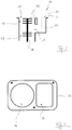
- Fig. 1 shows a vacuum pump 10 with a first pumping stage 12 and a second pumping stage 14.
- the two pumping stages 12, 14 are arranged coaxially and each have a plurality of rotors 15 and a common pumping shaft 16.
- the pump shaft 16 is driven by a motor, not shown, to a rotary motion.
- the vacuum pump 10 is a so-called split-flow pump which has a first inlet opening 18 and a second inlet opening 20.
- the first inlet opening 18 is assigned to the first pumping stage 12. That the first pumping stage 12 sucks gas from a recipient connected to the pump 10 and supplies it to the second pumping stage 14.
- the second inlet opening 20 communicates via a dispensing channel 22 with a dispensing opening 24, which is arranged between the first pumping stage 12 and the second pumping stage 14. That At the two inlet openings 18, 20 are at different pressure levels.
- connection flange 26 For attachment of the pump 10 to the recipient, a connection flange 26 is provided. In the illustrated example, it forms an end face of the vacuum pump 10, which is connected to the recipient. It may be integrally formed with a housing or housing portion of the pump 10. But it is also possible to design it as a separate component, which is connectable to the housing or with one or more housing portion (s).
- Fig. 2 shows the front side of the pump 10 in a plan view.
- the connecting flange 26 has a substantially rectangular basic shape (rounded rectangle Corners). Other geometric basic shapes of the connecting flange 26 are also conceivable.
- At least the second inlet opening 20 has a substantially rectangular basic shape.
- a square basic shape can also be chosen.
- the first inlet port 18 is circular in the present example to avoid a geometry change between the inlet port 18 and the rotor of the first pumping stage 12. On the one hand, this results in that the first pumping stage 12 can be arranged very close to the first inlet opening 18. On the other hand, the occurrence of vortices, which are difficult to avoid in a geometry change of the flow path to be flowed through by the gas, virtually impossible.
- FIG. 2 Furthermore, three attachment pumps 32, 32 'can be seen.
- the pump 10 When mounting the pump 10 to the corresponding recipient, the pump 10 is first hung on the arranged on a longitudinal side of the connecting flange 26 mounting pumps 32. The assembly is completed, in which a fixation by means of the attachment point 32 'takes place.
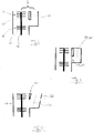
- the cross-sectional area of the second inlet opening 20 ie, its area A1 substantially exactly as large as a surface area A2 of the tapping opening 24 (cf. Fig. 4 ).
- a channel axis 28 of the dispensing channel 22 is arranged substantially parallel to the axis of rotation of the pump shaft 16.
- a distance D between the pump shaft 16 and the channel axis 28 is less than 1.2 times the diameter of the rotors 15 of the first pumping stage 12, which in the present embodiment is exactly the same size as that of the rotors 15 of the second pumping stage 14.
- a parallel arrangement of the pump shaft 16 and the dispensing channel 22 or its axis 28 is not absolutely necessary.
- the housing portion 31 and the dispensing channel 22 forming housing portion 32 may be separate components. However, a one-piece design of the housing of the pump 10 is possible and advantageous in many cases.
- the housing or its components 30, 31, 32 may be, for example, milling and / or castings.
Landscapes
- Engineering & Computer Science (AREA)
- Mechanical Engineering (AREA)
- General Engineering & Computer Science (AREA)
- Non-Positive Displacement Air Blowers (AREA)
- Structures Of Non-Positive Displacement Pumps (AREA)
Abstract
Description
- Die vorliegende Erfindung betrifft eine Vakuumpumpe, insbesondere Turbomolekularpumpe, mit zumindest einer ersten Pumpstufe mit zumindest einem ersten Rotor und mit zumindest einer zweiten Pumpstufe mit zumindest einem zweiten Rotor. Insbesondere ist die Drehachse des zweiten Rotors koaxial zu der des ersten Rotors angeordnet.
- Bei sog. Splitflow-Pumpen können zwei oder mehr Anzapfungen vorgesehen sein, die unterschiedlichen Druckniveaus zugeordnet sind. Üblicherweise sind die beiden Anzapfungen nebeneinander angeordnet. Aufgrund der herkömmlicherweise kreisrunden Geometrie dieser auch als Ports bezeichneten Anzapfungen ergibt sich ein nicht unerheblicher Bauraumbedarf. Die Ports können bei geforderten Mindestquerschnittsflächen nicht beliebig nah nebeneinander angeordnet werden.
- Es ist daher eine Aufgabe der vorliegenden Erfindung, eine Pumpe der eingangs beschriebenen Art zu schaffen, die einen möglichst geringen Bauraumbedarf aufweist.
- Erfindungsgemäß umfasst die Pumpe eine der ersten Pumpstufe zugeordnete Einlassöffnung, die in der Regel im Wesentlichen kreisrund ausgestaltet ist, eine der zweiten Pumpstufe zugeordnete zweite Einlassöffnung, wobei letztere eine im Wesentlichen rechteckige oder quadratische Grundform aufweist. Die erste und die zweite Einlassöffnung sind an einer axialen Stirnseite der Vakuumpumpe angeordnet. Die zweite Einlassöffnung steht zudem über einen Zapfkanal mit einer Zapföffnung verbunden, die - in axialer Richtung der Pumpe gesehen - zwischen der ersten und der zweiten Pumpstufe angeordnet ist.
- Durch die rechteckige oder quadratische Grundform der zweiten Einlassöffnung kann diese - bei gleicher Größe der Querschnittsfläche - näher an der ersten Einlassöffnung angeordnet werden, als dies bei einer kreisrund ausgeformten zweiten Einlassöffnung der Fall wäre. Die beiden Mittelpunkte der beiden Einlassöffnungen können somit nah aneinander rücken, sodass der Bauraumbedarf der Vakuumpumpe in einer Richtung quer, insbesondere senkrecht zur Drehachse des bzw. der Rotoren verringert wird.
- Insbesondere weisen der erste und der zweite Rotor eine gemeinsame Pumpenwelle auf. Der erste und der zweite Rotor können zudem einen im Wesentlichen gleichen Durchmesser aufweisen, bei einer Pumpe mit einer Pumpleistung von etwa 300 I/Sekunde z.B. 100 bis 140 mm.
- Weitere Ausführungsformen der Erfindung sind in der Beschreibung, den Ansprüchen und den beigefügten Figuren beschrieben.
- Gemäß einer Ausführungsform der erfindungsgemäßen Vakuumpumpe weist die erste Einlassöffnung einen im Wesentlichen gleichen oder geringfügig größeren Durchmesser auf wie der erste Rotor. Dies ermöglicht eine große räumliche Nähe zwischen dem ersten Rotor und der ersten Einlassöffnung.
- Gemäß einer weiteren Ausführungsform liegen die erste und die zweite Einlassöffnung im Wesentlichen in einer Ebene, insbesondere in einer Ebene senkrecht zu der eingangs genannten Drehachse. Diese Maßnahme vereinfacht den Anschluss der Geometrie der Pumpe an ein zu evakuierendes System.
- Eine Querschnittsgeometrie der zweiten Einlassöffnung kann im Wesentlichen einer Querschnittsgeometrie des Zapfkanals und/oder der Zapföffnung entsprechen. Durch die möglichst weitgehende Vermeidung von Geometriewechseln im Bereich des Zapfkanals bzw. der ihm zugeordneten Öffnungen kann die Entstehung von Verwirbelungen minimiert werden. Insbesondere enthält der Zapfkanal keine Absätze, Vorsprünge, Auskragungen oder ähnliches.
- Es hat sich als vorteilhaft herausgestellt, wenn ein Abstand eines Mittelpunkts der ersten Einlassöffnung von einem Mittelpunkt der zweiten Einlassöffnung weniger als das 1,2-fache eines Durchmessers des ersten und/oder des zweiten Rotors beträgt.
- Eine weitere Vereinfachung des Anschlusses der Pumpe an einen Rezipienten wird dadurch erreicht, wenn ein Flansch zur Befestigung der Pumpe an dem Rezipienten die erste und die zweite Einlassöffnung umfasst.
- Ein Flansch, insbesondere der vorstehend beschriebene Flansch, kann zur Befestigung der Pumpe an einem Rezipienten einstückig mit einem Gehäuse der Vakuumpumpe ausgebildet sein. Es ist auch möglich, dass ein Flansch zur Befestigung der Pumpe an einem Rezipienten eine ungerade Anzahl von Befestigungspunkten aufweist, insbesondere drei Befestigungspunkte. Bei der Montage wird die Pumpe dann beispielsweise zunächst in zwei Befestigungspunkte eingehängt. Der dritte Befestigungspunkt dient dann zum Fixieren ("Festziehen") der Pumpe. Diese Maßnahme vereinfacht die Montage in nicht unerheblicher Weise.
- Ein Flansch zur Befestigung der Pumpe an einem Rezipienten kann zumindest einen Montageabschnitt aufweisen, insbesondere eine oder mehrere Einfräsungen, der zu Montagezwecken mit zumindest einem komplementär ausgebildeten Montageabschnitt an dem Rezipienten zusammenwirkt. Insbesondere ist der Montageabschnitt des Flanschs derart ausgebildet, dass er in den Montageabschnitt des Rezipienten einschiebbar ist. Beispielsweise besitzt die Pumpe am Flansch Einfräsungen, mit denen die Pumpe bei der Montage in eine Aufhängung des Rezipienten geschoben werden kann. Dadurch wird die Pumpe schon gehalten und es können leichter die eigentlichen Montageschrauben befestigt/angezogen werden. Diese Einfräsungen zur einfacheren Montage können auch einfache Bohrungen sein.
- Gemäß einer weiteren Ausführungsform der erfindungsgemäßen Vakuumpumpe ist eine Kanalachse des Zapfkanals im Wesentlichen parallel zu der Drehachse des ersten und/oder zweiten Rotors angeordnet. Es ist jedoch auch möglich, die Kanalachse schräg zu der genannten Drehachse anzuordnen, falls dies im jeweils vorliegenden Fall zu einer Verbesserung der Strömungsverhältnisse im Inneren der Pumpe führt. In vielen Fällen wird durch diese Maßnahme nämlich ein besserer Strömungsleitwert erzielt und es treten weniger Strömungsabrisse auf.
- Die Zapföffnung kann eine im Wesentlichen rechteckige oder quadratische Grundform aufweisen.
- Zur Vereinfachung der Herstellung und/oder des Zusammenbaus der Pumpe kann ein dem Zapfkanal umfassender Gehäuseabschnitt einstückig mit einem die Pumpstufen umfassenden Gehäuseabschnitt der Vakuumpumpe ausgebildet sein.
- Nachfolgend wird die vorliegende Erfindung rein beispielhaft anhand vorteilhafter Ausführungsformen unter Bezugnahme auf die beigefügten Zeichnungen erläutert. Es zeigen:
- Fig. 1, 3, 4 und 5
- jeweils einen Querschnitt durch eine Ausführungsform der erfindungsgemäßen Vakuumpumpe und
- Fig. 2
- eine Draufsicht auf einen Anschlussflansch einer weiteren Ausführungsform der erfindungsgemäßen Vakuumpumpe.
-
Fig. 1 zeigt eine Vakuumpumpe 10 mit einer ersten Pumpstufe 12 und einer zweiten Pumpstufe 14. Die beiden Pumpstufen 12, 14 sind koaxial angeordnet und weisen jeweils mehrere Rotoren 15 und eine gemeinsame Pumpwelle 16 auf. Die Pumpwelle 16 wird von einem nicht gezeigten Motor zu einer Drehbewegung angetrieben. - Bei der Vakuumpumpe 10 handelt es sich um eine sog. Splitflow-Pumpe, die eine erste Einlassöffnung 18 und eine zweite Einlassöffnung 20 aufweist. Die erste Einlassöffnung 18 ist der ersten Pumpstufe 12 zugeordnet. D.h. die erste Pumpstufe 12 saugt Gas aus einem mit der Pumpe 10 verbunden Rezipienten und leitet es der zweiten Pumpstufe 14 zu.
- Die zweite Einlassöffnung 20 steht über einen Zapfkanal 22 mit einer Zapföffnung 24 in Verbindung, die zwischen der ersten Pumpstufe 12 und der zweiten Pumpstufe 14, angeordnet ist. D.h. an den beiden Einlassöffnungen 18, 20 liegen unterschiedliche Druckniveaus an.
- Zur Befestigung der Pumpe 10 an dem Rezipienten ist ein Anschlussflansch 26 vorgesehen. In dem dargestellten Beispiel bildet er eine Stirnseite der Vakuumpumpe 10, die mit dem Rezipienten verbunden wird. Er kann einstückig mit einem Gehäuse oder Gehäuseabschnitt der Pumpe 10 ausgebildet sein. Es ist aber auch möglich ihn als separates Bauteil auszugestalten, das mit dem Gehäuse oder mit einem oder mehreren Gehäuseabschnitt(en) verbindbar ist.
-
Fig. 2 zeigt die Stirnseite der Pumpe 10 in einer Draufsicht. Der Anschlussflansch 26 weist eine im Wesentlichen rechteckige Grundform auf (Rechteck mit abgerundeten Ecken). Es sind auch andere geometrische Grundformen des Anschlussflanschs 26 denkbar. - Um die beiden Einlassöffnungen 18, 20 möglichst nah beieinander anordnen zu können, weist zumindest die zweite Einlassöffnung 20 eine im Wesentlichen rechteckige Grundform auf. Eine quadratische Grundform kann ebenfalls gewählt werden.
- Die erste Einlassöffnung 18 ist in dem vorliegenden Beispiel kreisrund, um einen Geometriewechsel zwischen der Einlassöffnung 18 und dem Rotor der ersten Pumpstufe 12 zu vermeiden. Dies führt zum einen dazu, dass die erste Pumpstufe 12 sehr nah an der ersten Einlassöffnung 18 angeordnet werden kann. Zum anderen wird das Auftreten von Wirbeln, die bei einem Geometriewechsel des Strömungspfads der von dem Gas zu durchströmen ist, kaum zu vermeiden sind, praktisch ausgeschlossen.
- In
Fig. 2 sind ferner drei Befestigungspumpen 32, 32' zu sehen. Bei der Montage der Pumpe 10 an dem entsprechenden Rezipienten wird die Pumpe 10 zunächst an den an einer Längsseite des Anschlussflansches 26 angeordneten Befestigungspumpen 32 eingehängt. Die Montage wird abgeschlossen, in dem eine Fixierung mittels des Befestigungspunkts 32' erfolgt. - Um durch Geometriewechsel verursachte Verwirbelungen zu vermeiden, ist es in vielen Fällen vorteilhaft, die Zapföffnung 24 und/oder die Querschnittsgeometrie des Zapfkanals 22 an die der zweiten Einlassöffnung 20 anzupassen oder sogar im Wesentlichen gleich auszugestalten.
- Insbesondere kann vorgesehen sein, die Querschnittsfläche der zweiten Einlassöffnung 20 (also deren Flächeninhalt A1) im Wesentlichen genau so groß zu wählen, wie einen Flächeninhalt A2 der Zapföffnung 24 (vgl.
Fig. 4 ). - Wie in
Fig. 3 zu erkennen ist, ist eine Kanalachse 28 des Zapfkanals 22 im Wesentlichen parallel zu der Drehachse der Pumpwelle 16 angeordnet. Ein Abstand D zwischen der Pumpwelle 16 und der Kanalachse 28 beträgt weniger als das 1,2-fache des Durchmessers der Rotoren 15 der ersten Pumpstufe 12, der im vorliegenden Ausbildungsbeispiel genau so groß ist wie der der Rotoren 15 der zweiten Pumpstufe 14. - Eine parallele Anordnung der Pumpwelle 16 und des Zapfkanals 22 bzw. seiner Achse 28 ist jedoch nicht zwingend notwendig. Zur Verbesserung des Leitwerts kann es vorgesehen sein, den Zapfkanal 22 schräg zu einer Längsachse der Pumpe 10 anzuordnen, wie in
Fig. 5 gezeigt ist. Dadurch kann auch ein Gehäuseabschnitt 30 zwischen dem Kanal 22 und einem Gehäuseabschnitt 31, der die Pumpstufen 12, 14 aufnimmt, keilförmig ausgestaltet werden, sodass Strömungsabrisse an dessen stromabwärtigen Ende minimiert werden. - Der Gehäuseabschnitt 31 und ein dem Zapfkanal 22 bildender Gehäuseabschnitt 32 können separate Bauteile sein. Jedoch ist auch eine einstückige Ausgestaltung des Gehäuses der Pumpe 10 möglich und in vielen Fällen auch vorteilhaft. Das Gehäuse bzw. dessen Komponenten 30, 31, 32 können beispielsweise Fräs- und/oder Gussteile sein.
-
- 10
- Vakuumpumpe
- 12
- erste Pumpstufe
- 14
- zweite Pumpstufe
- 15
- Rotor
- 16
- Pumpwelle
- 18
- erste Einlassöffnung
- 20
- zweite Einlassöffnung
- 22
- Zapfkanal
- 24
- Zapföffnung
- 26
- Anschlussflansch
- 28
- Kanalachse
- 30, 31, 32
- Gehäuseabschnitt
- 32, 32'
- Befestigungspunkt
- A1,A2
- Flächeninhalt
- D
- Abstand
Claims (13)
- Vakuumpumpe, insbesondere Turbomolekularpumpe, mit zumindest einer ersten Pumpstufe (12) mit zumindest einem ersten Rotor (15) und mit zumindest einer zweiten Pumpstufe (14) mit zumindest einem zweiten Rotor (15), dessen Drehachse insbesondere koaxial zu der des ersten Rotors angeordnet ist, wobei eine erste, im Wesentlichen kreisförmige und der ersten Pumpstufe (12) zugeordnete erste Einlassöffnung (18) und eine der zweiten Pumpstufe (20) zugeordnete zweite Einlassöffnung (22), die eine im Wesentlichen rechteckige oder quadratische Grundform aufweist, vorgesehen sind, wobei die erste und die zweite Einlassöffnung (18, 20) an einer axialen Stirnseite der Vakuumpumpe angeordnet sind und die zweite Einlassöffnung (20) über einen Zapfkanal (22) mit einer Zapföffnung (24) verbunden ist, die zwischen der ersten und der zweiten Pumpstufe (12, 14) angeordnet ist.
- Vakuumpumpe nach Anspruch 1,
dadurch gekennzeichnet, dass
die erste Einlassöffnung (18) einen im Wesentlichen gleichen oder geringfügig größeren Durchmesser aufweist, wie der erste Rotor (15). - Vakuumpumpe nach Anspruch 1 oder 2,
dadurch gekennzeichnet, dass
die erste und die zweite Einlassöffnung (18, 20) im Wesentlichen in einer Ebene liegen. - Vakuumpumpe nach zumindest einem der vorgenannten Ansprüche,
dadurch gekennzeichnet, dass
eine Querschnittsgeometrie der zweiten Einlassöffnung (18) im Wesentlichen einer Querschnittsgeometrie des Zapfkanals (22) und/oder der Zapföffnung (24) entspricht. - Vakuumpumpe nach zumindest einem der vorgenannten Ansprüche,
dadurch gekennzeichnet, dass
ein Abstand (D) eines Mittelpunkts der ersten Einlassöffnung (18) von einem Mittelpunkt der zweiten Einlassöffnung (20) weniger als das 1,2-fache eines Durchmessers des ersten und/oder des zweiten Rotors (15) beträgt. - Vakuumpumpe nach zumindest einem der vorgenannten Ansprüche,
dadurch gekennzeichnet, dass
ein Flansch (26) zur Befestigung der Pumpe an einem Rezipienten die erste und die zweite Einlassöffnung (18, 20) umfasst. - Vakuumpumpe nach zumindest einem der vorgenannten Ansprüche,
dadurch gekennzeichnet, dass
ein Flansch (26) zur Befestigung der Pumpe an einem Rezipienten einstückig mit einem Gehäuse der Vakuumpumpe ausgebildet ist. - Vakuumpumpe nach zumindest einem der vorgenannten Ansprüche,
dadurch gekennzeichnet, dass
ein Flansch (26) zur Befestigung der Pumpe an einem Rezipienten eine ungerade Anzahl an Befestigungspunkten (32, 32'), insbesondere drei Befestigungspunkte (32, 32') aufweist. - Vakuumpumpe nach zumindest einem der vorgenannten Ansprüche,
dadurch gekennzeichnet, dass
ein Flansch (26) zur Befestigung der Pumpe an einem Rezipienten zumindest einen Montageabschnitt aufweist, insbesondere zumindest eine Einfräsung, der zu Montagezwecken mit zumindest einem komplementär ausgebildeten Montageabschnitt an dem Rezipienten zusammenwirkt, insbesondere ist der Montageabschnitt des Flanschs (26) derart ausgebildet, dass er in den Montageabschnitt des Rezipienten einschiebbar ist. - Vakuumpumpe nach zumindest einem der vorgenannten Ansprüche,
dadurch gekennzeichnet, dass
eine Kanalachse (28) des Zapfkanals (22) im Wesentlichen parallel zu der Drehachse des ersten und/oder zweiten Rotors (15) angeordnet ist. - Vakuumpumpe nach zumindest einem der vorgenannten Ansprüche,
dadurch gekennzeichnet, dass
eine Kanalachse (28) des Zapfkanals (22) im Wesentlichen schräg zu der Drehachse des ersten und/oder zweiten Rotors (15) angeordnet ist. - Vakuumpumpe nach zumindest einem der vorgenannten Ansprüche,
dadurch gekennzeichnet, dass
die Zapföffnung (24) eine im Wesentlichen rechteckige oder quadratische Grundform aufweist. - Vakuumpumpe nach zumindest einem der vorgenannten Ansprüche,
dadurch gekennzeichnet, dass
ein den Zapfkanal (22) umfassender Gehäuseabschnitt (32) einstückig mit einem die Pumpstufen (12, 14) umfassenden Gehäuseabschnitt (31) der Vakuumpumpe ausgebildet ist.
Priority Applications (2)
| Application Number | Priority Date | Filing Date | Title |
|---|---|---|---|
| EP17182496.4A EP3296571B1 (de) | 2017-07-21 | 2017-07-21 | Vakuumpumpe |
| JP2018133907A JP6722724B2 (ja) | 2017-07-21 | 2018-07-17 | 真空ポンプ |
Applications Claiming Priority (1)
| Application Number | Priority Date | Filing Date | Title |
|---|---|---|---|
| EP17182496.4A EP3296571B1 (de) | 2017-07-21 | 2017-07-21 | Vakuumpumpe |
Publications (2)
| Publication Number | Publication Date |
|---|---|
| EP3296571A1 true EP3296571A1 (de) | 2018-03-21 |
| EP3296571B1 EP3296571B1 (de) | 2021-11-03 |
Family
ID=59384025
Family Applications (1)
| Application Number | Title | Priority Date | Filing Date |
|---|---|---|---|
| EP17182496.4A Active EP3296571B1 (de) | 2017-07-21 | 2017-07-21 | Vakuumpumpe |
Country Status (2)
| Country | Link |
|---|---|
| EP (1) | EP3296571B1 (de) |
| JP (1) | JP6722724B2 (de) |
Cited By (2)
| Publication number | Priority date | Publication date | Assignee | Title |
|---|---|---|---|---|
| EP3564538A1 (de) * | 2019-02-20 | 2019-11-06 | Pfeiffer Vacuum Gmbh | Vakuumsystem und verfahren zur herstellung eines solchen |
| EP4293232A1 (de) * | 2023-10-17 | 2023-12-20 | Pfeiffer Vacuum Technology AG | Pumpe |
Citations (5)
| Publication number | Priority date | Publication date | Assignee | Title |
|---|---|---|---|---|
| DE4331589A1 (de) * | 1992-12-24 | 1994-06-30 | Balzers Pfeiffer Gmbh | Vakuumpumpsystem |
| EP1852613A2 (de) * | 2006-05-04 | 2007-11-07 | Pfeiffer Vacuum Gmbh | Vakuumpumpe mit Gehäuse |
| US20100098558A1 (en) * | 2007-02-28 | 2010-04-22 | Makarov Alexander A | Vacuum Pump or Vacuum Apparatus with Vacuum Pump |
| EP2975268A2 (de) * | 2014-07-17 | 2016-01-20 | Pfeiffer Vacuum Gmbh | Vakuumsystem |
| WO2016193664A1 (en) * | 2015-06-01 | 2016-12-08 | Edwards Limited | Vacuum pump |
Family Cites Families (1)
| Publication number | Priority date | Publication date | Assignee | Title |
|---|---|---|---|---|
| US6193461B1 (en) * | 1999-02-02 | 2001-02-27 | Varian Inc. | Dual inlet vacuum pumps |
-
2017
- 2017-07-21 EP EP17182496.4A patent/EP3296571B1/de active Active
-
2018
- 2018-07-17 JP JP2018133907A patent/JP6722724B2/ja active Active
Patent Citations (5)
| Publication number | Priority date | Publication date | Assignee | Title |
|---|---|---|---|---|
| DE4331589A1 (de) * | 1992-12-24 | 1994-06-30 | Balzers Pfeiffer Gmbh | Vakuumpumpsystem |
| EP1852613A2 (de) * | 2006-05-04 | 2007-11-07 | Pfeiffer Vacuum Gmbh | Vakuumpumpe mit Gehäuse |
| US20100098558A1 (en) * | 2007-02-28 | 2010-04-22 | Makarov Alexander A | Vacuum Pump or Vacuum Apparatus with Vacuum Pump |
| EP2975268A2 (de) * | 2014-07-17 | 2016-01-20 | Pfeiffer Vacuum Gmbh | Vakuumsystem |
| WO2016193664A1 (en) * | 2015-06-01 | 2016-12-08 | Edwards Limited | Vacuum pump |
Cited By (2)
| Publication number | Priority date | Publication date | Assignee | Title |
|---|---|---|---|---|
| EP3564538A1 (de) * | 2019-02-20 | 2019-11-06 | Pfeiffer Vacuum Gmbh | Vakuumsystem und verfahren zur herstellung eines solchen |
| EP4293232A1 (de) * | 2023-10-17 | 2023-12-20 | Pfeiffer Vacuum Technology AG | Pumpe |
Also Published As
| Publication number | Publication date |
|---|---|
| EP3296571B1 (de) | 2021-11-03 |
| JP6722724B2 (ja) | 2020-07-15 |
| JP2019049257A (ja) | 2019-03-28 |
Similar Documents
| Publication | Publication Date | Title |
|---|---|---|
| EP4198311B1 (de) | Schraubenspindelpumpe | |
| EP2459425B1 (de) | Baugruppe bestehend aus einem ausgleichsbehälter und einem hauptzylinder für eine hydraulische kraftfahrzeugbremsanlage | |
| EP1651869A1 (de) | Laufrad für pumpen | |
| EP2143953A1 (de) | Pumpenaggregat | |
| EP2626511A2 (de) | Zweispindelige Schraubenspindelpumpe in zweiflutiger Bauweise mit Dichtung zwischen einem Lagerabschnitt und einem Förderabschnitt | |
| DE102009019721B4 (de) | Hydraulisches System | |
| EP4198260A1 (de) | Schraubenspindelpumpe | |
| EP0774583B1 (de) | Gehäuse für eine Kreiselpumpe | |
| EP3296571A1 (de) | Vakuumpumpe | |
| DE10242297A1 (de) | Kugelgewindetrieb | |
| DE10024741B4 (de) | Seitenkanalpumpe | |
| DE202013010204U1 (de) | Multi-Inlet-Vakuumpumpe | |
| EP1862674B1 (de) | Kreiselpumpe | |
| DE19645384C2 (de) | Stirnseitige Bauteilverbindung | |
| EP1954948B1 (de) | Pumpengehäuse mit 2-punkt-befestigung | |
| DE102020108266B4 (de) | Wellenbauteil-Kopplungsstruktur und Fluidmaschine mit selbiger | |
| WO2007028429A1 (de) | Zahnradpumpe | |
| EP1795754B1 (de) | Universalflansch | |
| WO2017102199A1 (de) | Differentiallageranordnung | |
| EP2100041B1 (de) | Motorkreiselpumpe | |
| WO2017021117A1 (de) | Verdrängerpumpe zur förderung eines fluides für einen verbraucher eines kraftfahrzeuges | |
| DE112016002461T5 (de) | Zentrifugalpumpe | |
| DE102014108922A1 (de) | Schließzylindersystem | |
| EP1318276A2 (de) | Bajonettverbindung für ein Ringgehäuse eines Hochdruckkompressors einer Gasturbine | |
| WO2020182270A1 (de) | Seitenkanalgebläse |
Legal Events
| Date | Code | Title | Description |
|---|---|---|---|
| PUAI | Public reference made under article 153(3) epc to a published international application that has entered the european phase |
Free format text: ORIGINAL CODE: 0009012 |
|
| STAA | Information on the status of an ep patent application or granted ep patent |
Free format text: STATUS: THE APPLICATION HAS BEEN PUBLISHED |
|
| AK | Designated contracting states |
Kind code of ref document: A1 Designated state(s): AL AT BE BG CH CY CZ DE DK EE ES FI FR GB GR HR HU IE IS IT LI LT LU LV MC MK MT NL NO PL PT RO RS SE SI SK SM TR |
|
| AX | Request for extension of the european patent |
Extension state: BA ME |
|
| STAA | Information on the status of an ep patent application or granted ep patent |
Free format text: STATUS: REQUEST FOR EXAMINATION WAS MADE |
|
| 17P | Request for examination filed |
Effective date: 20180910 |
|
| RBV | Designated contracting states (corrected) |
Designated state(s): AL AT BE BG CH CY CZ DE DK EE ES FI FR GB GR HR HU IE IS IT LI LT LU LV MC MK MT NL NO PL PT RO RS SE SI SK SM TR |
|
| GRAP | Despatch of communication of intention to grant a patent |
Free format text: ORIGINAL CODE: EPIDOSNIGR1 |
|
| STAA | Information on the status of an ep patent application or granted ep patent |
Free format text: STATUS: GRANT OF PATENT IS INTENDED |
|
| INTG | Intention to grant announced |
Effective date: 20210726 |
|
| GRAS | Grant fee paid |
Free format text: ORIGINAL CODE: EPIDOSNIGR3 |
|
| GRAA | (expected) grant |
Free format text: ORIGINAL CODE: 0009210 |
|
| STAA | Information on the status of an ep patent application or granted ep patent |
Free format text: STATUS: THE PATENT HAS BEEN GRANTED |
|
| AK | Designated contracting states |
Kind code of ref document: B1 Designated state(s): AL AT BE BG CH CY CZ DE DK EE ES FI FR GB GR HR HU IE IS IT LI LT LU LV MC MK MT NL NO PL PT RO RS SE SI SK SM TR |
|
| REG | Reference to a national code |
Ref country code: GB Ref legal event code: FG4D Free format text: NOT ENGLISH |
|
| REG | Reference to a national code |
Ref country code: AT Ref legal event code: REF Ref document number: 1444188 Country of ref document: AT Kind code of ref document: T Effective date: 20211115 Ref country code: CH Ref legal event code: EP |
|
| REG | Reference to a national code |
Ref country code: DE Ref legal event code: R096 Ref document number: 502017011880 Country of ref document: DE |
|
| REG | Reference to a national code |
Ref country code: IE Ref legal event code: FG4D Free format text: LANGUAGE OF EP DOCUMENT: GERMAN |
|
| REG | Reference to a national code |
Ref country code: LT Ref legal event code: MG9D |
|
| REG | Reference to a national code |
Ref country code: NL Ref legal event code: MP Effective date: 20211103 |
|
| PG25 | Lapsed in a contracting state [announced via postgrant information from national office to epo] |
Ref country code: RS Free format text: LAPSE BECAUSE OF FAILURE TO SUBMIT A TRANSLATION OF THE DESCRIPTION OR TO PAY THE FEE WITHIN THE PRESCRIBED TIME-LIMIT Effective date: 20211103 Ref country code: LT Free format text: LAPSE BECAUSE OF FAILURE TO SUBMIT A TRANSLATION OF THE DESCRIPTION OR TO PAY THE FEE WITHIN THE PRESCRIBED TIME-LIMIT Effective date: 20211103 Ref country code: FI Free format text: LAPSE BECAUSE OF FAILURE TO SUBMIT A TRANSLATION OF THE DESCRIPTION OR TO PAY THE FEE WITHIN THE PRESCRIBED TIME-LIMIT Effective date: 20211103 Ref country code: BG Free format text: LAPSE BECAUSE OF FAILURE TO SUBMIT A TRANSLATION OF THE DESCRIPTION OR TO PAY THE FEE WITHIN THE PRESCRIBED TIME-LIMIT Effective date: 20220203 |
|
| PG25 | Lapsed in a contracting state [announced via postgrant information from national office to epo] |
Ref country code: IS Free format text: LAPSE BECAUSE OF FAILURE TO SUBMIT A TRANSLATION OF THE DESCRIPTION OR TO PAY THE FEE WITHIN THE PRESCRIBED TIME-LIMIT Effective date: 20220303 Ref country code: SE Free format text: LAPSE BECAUSE OF FAILURE TO SUBMIT A TRANSLATION OF THE DESCRIPTION OR TO PAY THE FEE WITHIN THE PRESCRIBED TIME-LIMIT Effective date: 20211103 Ref country code: PT Free format text: LAPSE BECAUSE OF FAILURE TO SUBMIT A TRANSLATION OF THE DESCRIPTION OR TO PAY THE FEE WITHIN THE PRESCRIBED TIME-LIMIT Effective date: 20220303 Ref country code: PL Free format text: LAPSE BECAUSE OF FAILURE TO SUBMIT A TRANSLATION OF THE DESCRIPTION OR TO PAY THE FEE WITHIN THE PRESCRIBED TIME-LIMIT Effective date: 20211103 Ref country code: NO Free format text: LAPSE BECAUSE OF FAILURE TO SUBMIT A TRANSLATION OF THE DESCRIPTION OR TO PAY THE FEE WITHIN THE PRESCRIBED TIME-LIMIT Effective date: 20220203 Ref country code: NL Free format text: LAPSE BECAUSE OF FAILURE TO SUBMIT A TRANSLATION OF THE DESCRIPTION OR TO PAY THE FEE WITHIN THE PRESCRIBED TIME-LIMIT Effective date: 20211103 Ref country code: LV Free format text: LAPSE BECAUSE OF FAILURE TO SUBMIT A TRANSLATION OF THE DESCRIPTION OR TO PAY THE FEE WITHIN THE PRESCRIBED TIME-LIMIT Effective date: 20211103 Ref country code: HR Free format text: LAPSE BECAUSE OF FAILURE TO SUBMIT A TRANSLATION OF THE DESCRIPTION OR TO PAY THE FEE WITHIN THE PRESCRIBED TIME-LIMIT Effective date: 20211103 Ref country code: GR Free format text: LAPSE BECAUSE OF FAILURE TO SUBMIT A TRANSLATION OF THE DESCRIPTION OR TO PAY THE FEE WITHIN THE PRESCRIBED TIME-LIMIT Effective date: 20220204 Ref country code: ES Free format text: LAPSE BECAUSE OF FAILURE TO SUBMIT A TRANSLATION OF THE DESCRIPTION OR TO PAY THE FEE WITHIN THE PRESCRIBED TIME-LIMIT Effective date: 20211103 |
|
| PG25 | Lapsed in a contracting state [announced via postgrant information from national office to epo] |
Ref country code: SM Free format text: LAPSE BECAUSE OF FAILURE TO SUBMIT A TRANSLATION OF THE DESCRIPTION OR TO PAY THE FEE WITHIN THE PRESCRIBED TIME-LIMIT Effective date: 20211103 Ref country code: SK Free format text: LAPSE BECAUSE OF FAILURE TO SUBMIT A TRANSLATION OF THE DESCRIPTION OR TO PAY THE FEE WITHIN THE PRESCRIBED TIME-LIMIT Effective date: 20211103 Ref country code: RO Free format text: LAPSE BECAUSE OF FAILURE TO SUBMIT A TRANSLATION OF THE DESCRIPTION OR TO PAY THE FEE WITHIN THE PRESCRIBED TIME-LIMIT Effective date: 20211103 Ref country code: EE Free format text: LAPSE BECAUSE OF FAILURE TO SUBMIT A TRANSLATION OF THE DESCRIPTION OR TO PAY THE FEE WITHIN THE PRESCRIBED TIME-LIMIT Effective date: 20211103 Ref country code: DK Free format text: LAPSE BECAUSE OF FAILURE TO SUBMIT A TRANSLATION OF THE DESCRIPTION OR TO PAY THE FEE WITHIN THE PRESCRIBED TIME-LIMIT Effective date: 20211103 |
|
| REG | Reference to a national code |
Ref country code: DE Ref legal event code: R097 Ref document number: 502017011880 Country of ref document: DE |
|
| PLBE | No opposition filed within time limit |
Free format text: ORIGINAL CODE: 0009261 |
|
| STAA | Information on the status of an ep patent application or granted ep patent |
Free format text: STATUS: NO OPPOSITION FILED WITHIN TIME LIMIT |
|
| 26N | No opposition filed |
Effective date: 20220804 |
|
| PG25 | Lapsed in a contracting state [announced via postgrant information from national office to epo] |
Ref country code: AL Free format text: LAPSE BECAUSE OF FAILURE TO SUBMIT A TRANSLATION OF THE DESCRIPTION OR TO PAY THE FEE WITHIN THE PRESCRIBED TIME-LIMIT Effective date: 20211103 |
|
| PG25 | Lapsed in a contracting state [announced via postgrant information from national office to epo] |
Ref country code: SI Free format text: LAPSE BECAUSE OF FAILURE TO SUBMIT A TRANSLATION OF THE DESCRIPTION OR TO PAY THE FEE WITHIN THE PRESCRIBED TIME-LIMIT Effective date: 20211103 |
|
| PG25 | Lapsed in a contracting state [announced via postgrant information from national office to epo] |
Ref country code: MC Free format text: LAPSE BECAUSE OF FAILURE TO SUBMIT A TRANSLATION OF THE DESCRIPTION OR TO PAY THE FEE WITHIN THE PRESCRIBED TIME-LIMIT Effective date: 20211103 |
|
| REG | Reference to a national code |
Ref country code: CH Ref legal event code: PL |
|
| REG | Reference to a national code |
Ref country code: BE Ref legal event code: MM Effective date: 20220731 |
|
| PG25 | Lapsed in a contracting state [announced via postgrant information from national office to epo] |
Ref country code: LU Free format text: LAPSE BECAUSE OF NON-PAYMENT OF DUE FEES Effective date: 20220721 Ref country code: LI Free format text: LAPSE BECAUSE OF NON-PAYMENT OF DUE FEES Effective date: 20220731 Ref country code: FR Free format text: LAPSE BECAUSE OF NON-PAYMENT OF DUE FEES Effective date: 20220731 Ref country code: CH Free format text: LAPSE BECAUSE OF NON-PAYMENT OF DUE FEES Effective date: 20220731 |
|
| PG25 | Lapsed in a contracting state [announced via postgrant information from national office to epo] |
Ref country code: BE Free format text: LAPSE BECAUSE OF NON-PAYMENT OF DUE FEES Effective date: 20220731 |
|
| PG25 | Lapsed in a contracting state [announced via postgrant information from national office to epo] |
Ref country code: IE Free format text: LAPSE BECAUSE OF NON-PAYMENT OF DUE FEES Effective date: 20220721 |
|
| REG | Reference to a national code |
Ref country code: AT Ref legal event code: MM01 Ref document number: 1444188 Country of ref document: AT Kind code of ref document: T Effective date: 20220721 |
|
| PG25 | Lapsed in a contracting state [announced via postgrant information from national office to epo] |
Ref country code: AT Free format text: LAPSE BECAUSE OF NON-PAYMENT OF DUE FEES Effective date: 20220721 |
|
| PG25 | Lapsed in a contracting state [announced via postgrant information from national office to epo] |
Ref country code: HU Free format text: LAPSE BECAUSE OF FAILURE TO SUBMIT A TRANSLATION OF THE DESCRIPTION OR TO PAY THE FEE WITHIN THE PRESCRIBED TIME-LIMIT; INVALID AB INITIO Effective date: 20170721 |
|
| PG25 | Lapsed in a contracting state [announced via postgrant information from national office to epo] |
Ref country code: MK Free format text: LAPSE BECAUSE OF FAILURE TO SUBMIT A TRANSLATION OF THE DESCRIPTION OR TO PAY THE FEE WITHIN THE PRESCRIBED TIME-LIMIT Effective date: 20211103 Ref country code: CY Free format text: LAPSE BECAUSE OF FAILURE TO SUBMIT A TRANSLATION OF THE DESCRIPTION OR TO PAY THE FEE WITHIN THE PRESCRIBED TIME-LIMIT Effective date: 20211103 |
|
| PG25 | Lapsed in a contracting state [announced via postgrant information from national office to epo] |
Ref country code: MT Free format text: LAPSE BECAUSE OF FAILURE TO SUBMIT A TRANSLATION OF THE DESCRIPTION OR TO PAY THE FEE WITHIN THE PRESCRIBED TIME-LIMIT Effective date: 20211103 |
|
| PGFP | Annual fee paid to national office [announced via postgrant information from national office to epo] |
Ref country code: IT Payment date: 20250724 Year of fee payment: 9 |
|
| PGFP | Annual fee paid to national office [announced via postgrant information from national office to epo] |
Ref country code: GB Payment date: 20250722 Year of fee payment: 9 |
|
| PGFP | Annual fee paid to national office [announced via postgrant information from national office to epo] |
Ref country code: CZ Payment date: 20250715 Year of fee payment: 9 |
|
| PG25 | Lapsed in a contracting state [announced via postgrant information from national office to epo] |
Ref country code: TR Free format text: LAPSE BECAUSE OF FAILURE TO SUBMIT A TRANSLATION OF THE DESCRIPTION OR TO PAY THE FEE WITHIN THE PRESCRIBED TIME-LIMIT Effective date: 20211103 |
|
| PGFP | Annual fee paid to national office [announced via postgrant information from national office to epo] |
Ref country code: DE Payment date: 20250926 Year of fee payment: 9 |