EP3301237B1 - Élément de revêtement et système d'eclairage - Google Patents
Élément de revêtement et système d'eclairage Download PDFInfo
- Publication number
- EP3301237B1 EP3301237B1 EP17193922.6A EP17193922A EP3301237B1 EP 3301237 B1 EP3301237 B1 EP 3301237B1 EP 17193922 A EP17193922 A EP 17193922A EP 3301237 B1 EP3301237 B1 EP 3301237B1
- Authority
- EP
- European Patent Office
- Prior art keywords
- light
- cladding element
- designed
- properties
- reflection layer
- Prior art date
- Legal status (The legal status is an assumption and is not a legal conclusion. Google has not performed a legal analysis and makes no representation as to the accuracy of the status listed.)
- Active
Links
Images

Classifications
-
- F—MECHANICAL ENGINEERING; LIGHTING; HEATING; WEAPONS; BLASTING
- F21—LIGHTING
- F21V—FUNCTIONAL FEATURES OR DETAILS OF LIGHTING DEVICES OR SYSTEMS THEREOF; STRUCTURAL COMBINATIONS OF LIGHTING DEVICES WITH OTHER ARTICLES, NOT OTHERWISE PROVIDED FOR
- F21V7/00—Reflectors for light sources
- F21V7/0008—Reflectors for light sources providing for indirect lighting
-
- E—FIXED CONSTRUCTIONS
- E04—BUILDING
- E04B—GENERAL BUILDING CONSTRUCTIONS; WALLS, e.g. PARTITIONS; ROOFS; FLOORS; CEILINGS; INSULATION OR OTHER PROTECTION OF BUILDINGS
- E04B9/00—Ceilings; Construction of ceilings, e.g. false ceilings; Ceiling construction with regard to insulation
- E04B9/006—Ceilings; Construction of ceilings, e.g. false ceilings; Ceiling construction with regard to insulation with means for hanging lighting fixtures or other appliances to the framework of the ceiling
-
- F—MECHANICAL ENGINEERING; LIGHTING; HEATING; WEAPONS; BLASTING
- F21—LIGHTING
- F21V—FUNCTIONAL FEATURES OR DETAILS OF LIGHTING DEVICES OR SYSTEMS THEREOF; STRUCTURAL COMBINATIONS OF LIGHTING DEVICES WITH OTHER ARTICLES, NOT OTHERWISE PROVIDED FOR
- F21V7/00—Reflectors for light sources
- F21V7/22—Reflectors for light sources characterised by materials, surface treatments or coatings, e.g. dichroic reflectors
-
- F—MECHANICAL ENGINEERING; LIGHTING; HEATING; WEAPONS; BLASTING
- F21—LIGHTING
- F21V—FUNCTIONAL FEATURES OR DETAILS OF LIGHTING DEVICES OR SYSTEMS THEREOF; STRUCTURAL COMBINATIONS OF LIGHTING DEVICES WITH OTHER ARTICLES, NOT OTHERWISE PROVIDED FOR
- F21V33/00—Structural combinations of lighting devices with other articles, not otherwise provided for
- F21V33/006—General building constructions or finishing work for buildings, e.g. roofs, gutters, stairs or floors; Garden equipment; Sunshades or parasols
-
- F—MECHANICAL ENGINEERING; LIGHTING; HEATING; WEAPONS; BLASTING
- F21—LIGHTING
- F21Y—INDEXING SCHEME ASSOCIATED WITH SUBCLASSES F21K, F21L, F21S and F21V, RELATING TO THE FORM OR THE KIND OF THE LIGHT SOURCES OR OF THE COLOUR OF THE LIGHT EMITTED
- F21Y2115/00—Light-generating elements of semiconductor light sources
- F21Y2115/10—Light-emitting diodes [LED]
Definitions
- the invention relates to a cladding element for at least partially covering a wall or a ceiling and to a lighting system for illuminating a room with at least one workstation and preferably several workstations.
- luminaires are used in different designs adapted to the respective application to illuminate rooms and workplaces.
- the aim is usually to use the luminaires to create light distribution curves that allow the best possible illumination for a specific situation.
- floor lamps are often used in offices to illuminate workstations such as desks. Although such lamps can sometimes provide good illumination for individual workstations, they can impair the use of the room and are often perceived as disruptive. In particular, such lamps typically have to be placed close to a workstation to ensure the best possible illumination, which is often undesirable and particularly impractical for workstations that change regularly.
- ceiling lights are also used to illuminate the workstations.
- Area lights can be relatively small and focused or larger and have a wider beam.
- ceiling lights can be used to illuminate workplaces in a preferred manner and although such lights are relatively unobtrusive because they are not placed in places where things are placed or people are present, they are relatively inflexible. Particularly in the case of workplaces that change regularly, for example in offices where workstation groups are formed depending on the project, such ceiling lights are usually too inflexible because they have to be moved, realigned and configured. Such ceiling lights are also often undesirable for interior design because they are typically permanently mounted and therefore cannot be redesigned.
- WO2013/102862A1 discloses a cladding element according to the preamble of claim 1.
- the object of the following invention is therefore to propose a system that enables a flexibly adaptable and designable, specific illumination of workplaces in a room.
- a cladding element for at least partially covering a ceiling or a wall of a room comprises a flat carrier substrate with a front side and a back side, a fastening structure arranged on the back side of the carrier substrate and a light-forming structure arranged on the front side of the carrier substrate.
- the fastening structure is designed to fasten the cladding element to a wall or a ceiling.
- the light-forming structure is designed to reflect a light beam directed at the cladding element and to generate predefined light properties in the reflected light.
- ceiling in connection with the invention can refer to an upper boundary of an open or closed room. Not necessarily but typically Room ceilings are aligned horizontally.
- wall in the same context can refer to a lateral boundary of the open or closed room. Walls are typically aligned vertically or essentially vertically. The ceiling and the wall can be formed by plastered masonry, panels, stretched textile materials, metals, concrete, glass, stone materials or the like.
- the term "for covering" in connection with the cladding element can be understood as arranging it on the ceiling or wall so that the ceiling or wall at the point where the cladding element is positioned is not visible from the room, or at least not completely visible.
- the cladding element can lie directly on the ceiling or wall, or it can be spaced apart from it.
- predefined light properties or “predefined lighting properties” in connection with the reflected light can refer to the fact that the lighting properties are specifically defined for the illumination of a room or a workplace via the properties of a luminous flux directed at the cladding element and the nature of the light shape structure.
- the light properties of the reflected light can be predefined in such a way that a light distribution curve (LVK) specifically intended for the workplace or the room involved is achieved. This allows a workplace to be advantageously illuminated in a targeted manner and/or an adapted, advantageous basic lighting can be created in the room.
- the predefined light properties can also be used to create different lighting atmospheres such as diffuse and/or directed. Lighting properties that are present without being adapted or included in the determination of the illumination of the room or workplace are not to be understood as predefined in this sense.
- the term "light distribution curve” is understood to mean a characterization of the light emitted by a lamp, which can be represented in a graphic.
- the light intensities in their various radiation directions are connected to form a curve.
- the light distribution describes the spatial distribution of the light.
- the shape and symmetry of the Light distribution is characterized by a depth or width and a symmetry of the radiation.
- the term "workplace” in this context can refer to a typically horizontal or quasi-horizontal surface on which certain activities are carried out.
- the workplace can be a table surface and in particular a surface of an office or desk. Or it can be an area of a room with or without one or more tables. It can also be just part of a table, such as a conference table in a meeting room.
- targeted illumination in connection with the workplace can refer to the creation of a preferred light distribution curve (LCC).
- LCC preferred light distribution curve
- the workplace should be sufficiently illuminated and glare should be avoided.
- Targeted illumination does not create illumination of the workplace via basic lighting in the room, but rather a specific illumination of the workplace that is independent of the basic lighting.
- the illumination of the workplace differs from the basic lighting of the room.
- the workplace should often be illuminated more brightly to allow comfortable reading and writing or working.
- pure workplace lighting or a combination of workplace and basic lighting can be achieved.
- the term "light beam” or luminous flux or beam can refer to a stream of visible light. This can be light emitted by a lamp or light source and in particular visible light emitted by a light emitter.
- the light beam or beam can be a bundle of rays, whereby a bundle of rays is understood to mean a number of light rays that run exactly or almost parallel to one another or predominantly in a similar direction.
- the light beam can also have a propagation angle as typically occurs with point light sources.
- the cladding element can be used to control the light locally, for example on a wall or a workstation. Or intermediate values (dynamic light distribution curve). Alternatively or additionally, lighting moods can also be controlled, for example by setting the percentage of the directed and/or diffuse light component.
- the cladding element is advantageously designed to reflect at least 60% or at least 75% of the light beam directed onto the cladding element. In particular, this can be ensured in all embodiments of the cladding element.
- the cladding element according to the invention enables, among other things, the creation of a lighting object that can emit light in a targeted manner.
- This can be used to create a dematerialized light or a virtual light on the ceiling or wall.
- the creation of such a virtual light allows for great flexibility in the lighting and design of workplaces. For example, in rooms in which the workplaces change regularly, targeted lighting can be provided that can be adapted to the changes with relatively little effort, for example by simply repositioning the cladding element. For example, this can prevent ceiling lights from having to be moved and/or standing or floor lamps from having to be moved in order to enable adapted lighting of the room or the individual workplaces when conditions change.
- the cladding element according to the invention enables new possibilities in interior design.
- the virtual light can be perceived as a built-in light without actually having to be installed.
- the cladding element also enables workplaces to be appropriately illuminated in rooms in which it is not possible to install or add a light in or on the ceiling.
- the cladding element can be used to create ceiling lighting on ceilings that are not thick enough to be installed, that do not have enough load-bearing capacity to be installed or added, or that cannot be changed for reasons of monument preservation, for example. No electrical connection is required on the ceiling. This means that the ceiling can be completely without power, which is often advantageous and can prevent a relatively complex ceiling construction.
- the lighting system can also be advantageous in relatively low room heights. because there are no structures protruding from the ceiling.
- the cladding element can be used efficiently to illuminate ceilings that have a relatively low degree of reflection and would therefore have a relatively high energy consumption if they were used for lighting via reflection.
- the cladding element according to the invention can have the following advantages:
- the lamps or spotlights used can be designed relatively flexibly, since no large lamp head is necessary.
- protruding lamp heads are often used, which are relatively expensive and require a lot of material.
- the indirect lighting via the ceiling or wall, as made possible by the cladding element according to the invention can be perceived as particularly pleasant.
- light graphics can be created.
- the cladding element according to the invention can be preferred in interior design, since no stands or larger lighting objects need to be set up in the room. Shadows caused by direct light can be prevented.
- the light produced can come close to the impression of daylight, which is often perceived as pleasant. Maintenance and installation can be relatively simple.
- the cladding element In addition to attaching the cladding element exclusively to a ceiling or wall, it can also be attached to a ceiling or one or more walls of the room at the same time. This makes it possible to create a lighting object across a corner, which may be preferred in certain applications. For example, the variability of the solid angle of a spotlight means that more wall can be illuminated and thus a higher vertical luminance can be achieved, which can be helpful for improving facial recognition, for example. At the same time, additional design freedom (degree of freedom) can be created for interior design.
- the cladding element according to the invention thus enables the creation of a system with which a flexibly adjustable illumination can be achieved, for example, of workstations in a room or the entire room. It can also be implemented relatively efficiently and inexpensively.
- the fastening structure can be designed in any way to suit the cladding element and the associated ceiling or wall.
- it can include openings for passing through or receiving screws, nails or the like, or it can be equipped with hooks, clamps or similar fastening means.
- it can have a Velcro strip or part of a Velcro fastener that is mounted on the ceiling or wall to interact with a corresponding part of the Velcro fastener.
- it can be designed for electrostatic adhesion.
- the fastening structure preferably comprises an adhesive.
- the adhesive can be designed as an adhesive layer on the carrier substrate or as a double-sided adhesive tape. With such an adhesive, the cladding element can be efficiently and securely attached directly to the ceiling or wall. Alternatively, the cladding element can also be suspended directly or at a distance from the ceiling.
- the fastening structure can comprise suspension elements such as cables, chains, straps, rods or the like, or can be designed to be mounted on such suspension elements.
- the fastening structure preferably comprises magnets.
- magnets can be applied over the surface or partially or piece by piece.
- the cladding element can be attached to the wall or ceiling simply and efficiently. For example, ceilings with metal panels are widespread. Such a cladding element could be attached to them simply and detachably.
- the carrier substrate can have any suitable basic shape, such as a rectangular or circular surface. It can also be shaped as a graphic shape, such as a heart or a body.
- the term "carrier substrate” can refer to any typically flat structure that provides support for the fastening structure and the light-forming structure.
- the carrier substrate can be a textile such as a cloth.
- the carrier substrate is a film. Such a film can be efficiently manufactured, made robust and flexibly shaped.
- the carrier substrate is a plate.
- the plate can be rigid or solid or elastic or bendable. Such a plate enables a robust implementation of the cladding element.
- such a plate can itself be designed as panels.
- the reflected light can be diffuse or essentially diffuse.
- the light-forming structure preferably comprises reflection, refraction and/or diffraction contours that direct the reflected light.
- the reflection contours enable the reflected light to be directed, whereby the emission characteristics of the reflected light can be set or determined. They can in particular be designed as a micro- or nanostructure.
- the light-forming structure can also be provided with a light-directing coating, anodized, with a galvanic layer or similar. The light reflected in this way can be partially directed or partially diffuse or essentially completely directed. Such light is preferred in many applications.
- the reflection, refraction and/or diffraction contours of the light-forming structure preferably comprise cones, prisms, line structures and/or pyramids.
- these light-directing contours can enable a directed, diffuse or partially diffuse reflection of the light.
- they can have a refractive effect by shaping light that has already been reflected, for example via lenses.
- the reflection contours can be arranged adjacent to a reflective layer such as a mirror layer. They can also have a diffractive effect. A combination of these effects can also be possible.
- the light-directing contours can efficiently direct the reflected light and a preferred light distribution curve can be created.
- the light shaping structure comprises a first reflection layer and a second reflection layer, wherein the first reflection layer is closer to the front side of the carrier substrate than the second reflection layer, the first reflection layer and the second reflection layer have different reflection properties, and the second reflection layer is partially translucent.
- the two reflective layers can be created or produced in different ways. For example, they can be designed integrally, i.e. a reflective base layer is sprayed with a white or other colored paint (overspray). The reflected light is Density of the varnish more diffuse or more directed.
- the two reflective layers can also be integral in that they lie in one plane, for example as a print on a substrate such as a film or glass (print).
- the print can include a pattern with different properties. It can be important how the pattern is designed and in what sizes the pattern is printed. For example, on the one hand a large-area pattern can enable precise adjustment of the light properties.
- a small-area pattern can be desired in order to prevent patterned light at the target location and to create as flat a light as possible for aesthetic reasons.
- the pattern is preferably adapted to the intended use taking these requirements into account.
- the two reflective layers can be designed additively, i.e. the two reflective layers are each designed as a covering layer, with the second reflective layer being translucent in places.
- the second reflective layer can, for example, have a pattern with translucent and opaque areas, such as a checkerboard pattern.
- the second reflective layer is preferably partially transparent to light by being perforated.
- the perforations can be formed in any way. For example, they can be round, square or have other geometric shapes.
- the perforated second reflective layer can, for example, be checkerboard-like.
- Such a perforated second reflective layer allows great freedom in the design of the reflective properties of the cladding element as well as in its optical design.
- any images can be applied to the carrier substrate. Among other things, a two-tone version with reflective and white is possible. The radiation characteristics or atmosphere can then be adjusted via the density of the coating.
- the cladding element preferably comprises an adjusting device, wherein the light shape structure can be changed by means of the adjusting device in such a way that it sets the predefined light properties of the reflected light.
- the predefined light properties of the reflected light can also be changed.
- the light properties or the LDC can be adjusted with the adjusting device. In this way, the Efficiently adapt the cladding element to the specific current situation in the application of the cladding element.
- the light-forming structure preferably comprises pigments and the adjusting device comprises at least one electrode, the at least one electrode being designed to arrange the pigments.
- a background is silver and the pigments are white.
- the pigments can in particular be liquid pigments. Such pigments can be attracted or repelled and arranged using electricity.
- the term "arrange" in this context can refer to a displacement and/or alignment or directing of the pigments. By specifically directing and arranging the pigments, the light properties of the reflected light can be precisely and efficiently adjusted or adjusted.
- white pigments can be arranged in front of a reflective surface, for example of the carrier substrate, which can be arranged using the electrode.
- the pigments are preferably provided as movable particles in a film. Such a film can be produced efficiently, precisely and cost-effectively.
- the actuating device preferably comprises a control which regulates the supply of the at least one electrode.
- a control enables precise dosing and supply of current to the electrodes so that the pigments can be directed and positioned efficiently and precisely.
- the cladding element preferably comprises a photovoltaic element for supplying the actuating device and preferably other electrical consumers.
- the photovoltaic element can be a photovoltaic film. Such a film could be provided as a layer of the cladding element. Photovoltaic cells can also be made colored in film form nowadays. Such a photovoltaic film could thus be designed to generate energy and to reflect as the first or second reflection layer or another part of the light-forming structure.
- the light-forming structure comprises a clear liquid in which electrically charged darker particles or microparticles and oppositely electrically charged light particles or Microparticles are arranged.
- the light-forming structure can further comprise a voltage generator with which electrical voltages can be generated in the liquid of the light-forming structure.
- the particles or microparticles can be arranged systematically by applying an electrical voltage once, analogous to the way eBooks work. This means that the light properties can be adjusted efficiently and in a very versatile way. In addition, no energy is required to maintain the systematic arrangement of the particles.
- the light-forming structure has inhomogeneous reflection properties. With such a light-forming structure, a mixture of different preferred reflection properties can be achieved in an efficient manner.
- the light-forming structure has inhomogeneous reflection properties in particular in that it comprises several areas that are designed to reflect a light beam directed at the cladding element differently from one another. With such areas, inhomogeneous reflection properties can be created simply and effectively.
- the areas can in particular be distributed over many areas or over virtually the entire front side of the carrier substrate or extend onto it.
- the multiple regions of the light-forming structure comprise a diffuse region which is designed to partially diffusely or diffusely reflect a light beam directed at the cladding element.
- the diffuse region makes up at least about 50% or preferably at least about 60% or more preferably about 70% of the area with which the light beam directed at the cladding element can be reflected.
- Such a diffuse region in combination with a directionally reflecting region according to the invention, enables mixed reflection properties to be produced in an advantageous manner.
- the several areas of the light-form structure alternate with one another in a recurring manner. This enables a simple mixing of the reflection properties so that they cannot be perceived separately by an observer or can only be perceived to a limited extent. In this way, a preferred lighting or atmosphere can be created.
- at least one of the several areas of the light-form structure is designed to be dotted.
- the term "dotted" includes any dot-, spot-, dot- or speckle-shaped or similar arrangements. With such a design of the multiple areas, efficient the different reflection properties are mixed relatively finely.
- At least one of the several areas of the light-forming structure is produced by spraying with a dye.
- a dye in this context can be understood as a coloring substance with which a substrate can be colored or dyed.
- they can be designed as a spray paint to adhere to the substrate and thereby color it at least from the outside or from a visible side.
- the multiple regions are constructed from different materials, so that different reflecting regions have different materials. In this way, a total reflection can be precisely defined.
- the cladding element is preferably designed to be sound-absorbing.
- sound-absorbing refers to the absorption or absorption of sound waves in the audible range.
- DIN EN ISO 354:2003 it can be designed as perforated or equipped with perforated areas for sound absorption.
- the cladding element has a sound absorption coefficient of at least about 0.3 in a frequency range from about 100 Hz to about 4,000 Hz.
- the same element or component can be used to illuminate a workplace on the one hand and to protect the workplace from noise or unwanted sound on the other.
- Such a cladding element can also be used in other applications for lighting and simultaneous noise reduction.
- the cladding element can be designed as a multifunctional component, which can be advantageous in many applications. For example, with such a cladding element, a reverberation time of less than 0.6 seconds on average can be achieved.
- the cladding element preferably has a layer of sound-absorbing material.
- Such materials can be, for example, felt, foam, perforated wood, perforated foils, textiles or similar.
- the cladding element can be efficiently designed as a soundproofing component.
- the layer of sound-absorbing material is preferably arranged on the front of the carrier material. The front is typically directed towards the room or the workplace. In this way, the layer mentioned can absorb sound at the target location accordingly efficiently or protect it from noise.
- the layer of sound-absorbing material is preferably translucent. In this way, light can penetrate this layer and be reflected by a structure arranged behind it.
- Another aspect of the invention relates to a lighting system with a light emitter, a workstation and a cladding element in an embodiment described above.
- the cladding element is attached to a wall or ceiling of a room
- the light emitter is designed to emit a stream of visible light onto the cladding element
- the cladding element is designed such that the stream of visible light emitted by the light emitter onto the cladding element produces a lighting object with predefined lighting properties.
- the lighting object specifically illuminates the workstation.
- the "light emitter” as provided in the lighting system typically comprises at least one light source, in particular an LED light source, and an optical system with which the light emitted by the light source is adjusted or adapted.
- the light source together with the optical system generates the stream of visible light.
- luminaire object refers to a homogeneous or inhomogeneous closed light surface with a defined boundary or sharp edges.
- the luminaire object can have any shape on the cladding element. In particular, it can be round or polygonal.
- the luminaire object can be designed or set in such a way that the light surface does not have a homogeneous luminance distribution. This can, for example, be higher in the center.
- the human eye does not necessarily have to perceive this, However, it can be noticeable at the workplace.
- the lighting intensity can be adjusted between the wall and the table. The two extremes can be called “center beam” and "ring beam”.
- the term "defined boundary" refers to a reduction in the luminance on the cladding element to a maximum of 10%, a maximum of 5% or virtually 0%, which occurs over a maximum of about 30% of a diameter or a maximum of about 15% of a radius of the luminaire object or a central zone thereof.
- the central zone can be an area of the luminaire object that cannot be assigned to the defined boundary, i.e. a border zone.
- the central zone can be a homogeneous light surface or it can, for example, have a luminance gradient from the center to the edge zone.
- the diameter can be an approximate diameter if the luminaire object is not round. For example, if it is square, it can correspond to a diagonal of the square.
- the term “sharp edge” is understood to mean a reduction in luminance by at least about 20%, at least about 25%, at least about 30%, at least about 40% or at least about 50%, preferably to about 0%, wherein this reduction occurs over a maximum of about 10% of the diameter of the luminaire object or a central zone thereof.
- the lighting object can be a spotlight or any other type of light.
- such a lighting system can efficiently achieve the effects and advantages described above in connection with the cladding element in connection with a workplace.
- the light spotlight is fixed to the workstation.
- the workstation can be integrated into a table leg of a desk or attached to the edge of a table top of an office table.
- the light spotlight can be moved or migrate with the workstation or office table. This enables extremely flexible and simple lighting of workstations.
- the light emitter preferably has an adjusting unit with which the properties of the stream of visible light can be adjusted.
- the adjusting unit can be used to adjust, for example, the light color and/or the intensity. This enables the creation of an adapted and well-defined lighting object on the cladding element.
- the adjusting unit of the light emitter is preferably designed to change a direction of the flow of visible light. In addition, it is preferably designed to change a focus of the luminous flux.
- the light emitter can be equipped with a telescope, for example. In this way, the lighting object can be flexibly created on the cladding element and adapted to changing workplaces.
- the adjusting unit can enable a change in the focus and the beam angle. The focus can be used to adjust the edge sharpness of the lighting object and the angle can be used to adjust the size of the lighting object.
- the lighting system preferably comprises a monitoring unit that is connected to the adjusting unit of the light spotlight, the monitoring unit being designed to monitor the workplace and to activate the adjusting unit when a change in the workplace is detected, the adjusting unit adjusting the flow of visible light so that the illumination of the workplace by the lighting object of the cladding element remains constant.
- the change in the workplace can be, for example, a shifting of the workplace or the desk.
- a change in the height of the desk can also be a change in the workplace that is monitored and recorded by the monitoring unit.
- the light spotlight can be fixed in the room.
- the lighting object on the cladding element can be changed automatically so that the illumination of the workplace remains constant.
- the lighting system can therefore automatically adapt the lighting situation, the virtual ceiling light can, for example, move with the workplace and thus ensure constant illumination.
- the monitoring unit comprises a sensor that detects the position and/or orientation of the workstation.
- the sensor can be designed in particular to detect movements of the workstation. This enables an automated and rapid detection and recording of a change in the workplace.
- the stream of visible light emitted by the light emitter onto the cladding element is a directed or partially diffuse stream of visible light.
- the lighting object on the cladding element can be created particularly precisely and efficiently.
- the fastening structure of the cladding element comprises an adhesive.
- the fastening structure comprises magnets.
- the carrier substrate is a film.
- the carrier substrate is a plate.
- the light shape structure has reflection contours that direct the reflected light.
- the reflection contours of the light shape structure comprise cones, cones, prisms and/or pyramids.
- the second reflective layer is partially translucent by being perforated.
- the cladding element comprises an adjusting device, wherein the light shape structure can be changed by means of the adjusting device such that it sets the predefined light properties of the reflected light.
- the light-forming structure comprises pigments and the adjusting device comprises at least one electrode, wherein the at least one electrode is designed to arrange the pigments.
- the pigments are provided as a printed structure in a film.
- the actuating device comprises a controller which regulates the supply of the at least one electrode.
- the cladding element comprises a photovoltaic element for supplying the actuating device.
- a background is silver and the pigments are white.
- the light shape structure has inhomogeneous reflection properties.
- the light-forming structure has inhomogeneous reflection properties in that it comprises a plurality of regions which are designed to reflect a light beam directed onto the cladding element differently from one another.
- the plurality of regions of the light-forming structure comprise a diffuse region which is designed to partially diffusely or diffusely reflect a light beam directed onto the cladding element.
- the diffuse region comprises at least about 50% or at least about 60% or preferably about 70% of the area with which the light beam directed onto the cladding element is reflectable.
- the several areas of the light form structure alternate with each other repeatedly.
- At least one of the plurality of regions of the light shape structure is dotted.
- At least one of the plurality of regions of the light-forming structure is formed by spraying with a dye.
- the plurality of regions are constructed of different materials such that different reflective regions comprise different materials.
- the cladding element is designed to be sound-absorbing.
- the cladding element has a sound absorption coefficient of at least about 0.3 in a frequency range of about 100 Hz to about 4,000 Hz.
- the cladding element comprises a layer of sound-absorbing material.
- the layer of sound absorbing material is arranged on the front side of the carrier material.
- the layer of sound-absorbing material is translucent.
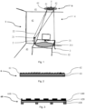
- Fig. 1 shows a first embodiment of a lighting system 1 according to the invention with a first embodiment of a cladding element 6 according to the invention.
- the lighting system 1 is installed in an office room 4 with a ceiling 41, walls 42 and a floor 43.
- a desk 3 with four table legs 32 and a table top 31 is arranged on the floor 43 of the office room 4.
- An upper side of the table top 31 forms a work station 311.
- the lighting system 1 comprises the workstation 311, the cladding element 6 and a light column 2 as a light source.
- the light column 2 is equipped with an LED light source 21, an optic and an adjusting device.
- the light column 2 can be configured or adjusted using the adjusting device.
- the light column 2 is set up on the floor 43 in front of an edge of the table top 31.
- the cladding element 6 is flat and pad-like and has an approximately circular basic shape. It is attached to the ceiling 41 and comprises a light-forming structure 61 that is directed downwards. The cladding element 6 thus covers the ceiling 41 at the point where it is mounted.
- the light-forming structure 61 of the cladding element 6 has a pyramid-shaped microstructure as a reflection contour. It can be designed as a matt scattering structure, as a reflective structure or as a mixture of these.
- the cladding element 6 further comprises a carrier film 62 as a flat carrier substrate with an upper front side and a lower back side.
- An adhesive layer 63 is arranged on the back of the carrier film as a fastening structure, which is designed to fasten the cladding element 6 to the ceiling 41.
- the light-forming structure 61 is arranged on the front side of the carrier film 62 and is designed to reflect a light beam directed at the cladding element 6 and to generate predefined light properties in the reflected light.
- the light column 2 emits a luminous flux 22 via its LED light source 21 and its optics, i.e. a current of visible light to the cladding element 6 attached to the ceiling 41.
- the light shape structure 61 with its reflection contour is designed such that the luminous flux 22 creates a spot 5 as a lighting object with predefined lighting properties or a predefined LDC.
- the spot 5 has a circular, homogeneous center zone 51 and a sharp-edged edge 52 as a finish.
- the light column 2 is configured such that the spot 5 created on the cladding element 6 preferentially illuminates the workstation 311. In particular, this illuminates or illuminates an area of the top of the desk 3 that is next to a screen arranged on the desk 3.
- Fig. 3 shows a second embodiment of a cladding element 60 according to the invention.
- the cladding element 60 comprises a carrier film 620 as a flat carrier substrate with an upper front side and a lower back side.
- a plurality of magnets 630 are arranged on the back of the carrier film 620 as a fastening structure.
- the magnets 630 are provided in particular for fastening the cladding element 60 to a metal ceiling or wall.
- a two-part light-forming structure is arranged on the front side of the carrier film 620, which comprises a first reflection layer 640 located closer to the front side of the carrier film 620 and a second reflection layer 610 located further away from the front side of the carrier film 620.
- the first reflection layer 640 is a mirror layer that reflects incident light in a directed manner.
- the second reflection layer 610 reflects the light diffusely.
- the first reflection layer 640 and the second reflection layer 610 therefore have different reflection properties.
- the second reflection layer 610 is perforated. In particular, it comprises square holes arranged in a checkerboard pattern through which light can pass to the first reflection layer 640. It is thus partially translucent.
- the two-part design of the light-forming structure allows the cladding element 60 to reflect light both diffusely and in a directed manner. This can produce a light distribution coefficient that is desired for many applications.
- a third embodiment of a cladding element 68 according to the invention is shown. It comprises a carrier film 628 as a flat carrier substrate with an upper front side and a lower back side. On the back of the carrier film 628 an adhesive layer 638 is provided as a fastening structure arranged. A light-forming structure 618 with a continuous flat mirror layer is attached to the front of the carrier film 628, which has pigments 6128 arranged in a substrate 6118. The substrate 6118 and the pigments 6128 can be provided as a printed structure in a film.
- the cladding element 68 further comprises an adjusting device with a positive electrode, i.e. an anode 6138, and a negative electrode, i.e. a cathode 6148. The anode 6138 and the cathode 6148 are located opposite one another at the edge of the substrate 6118.
- the cladding element 68 further comprises a control which is connected to the cathode 6148 and the anode 6138.
- the two electrodes can be adjusted so that the pigments 6128 are arranged and aligned.
- the reflection properties of the light-forming structure can be changed by means of the adjusting device so that the light properties of the light reflected by the cladding element 68 are adjusted.
- Some pigments are silver and therefore directionally reflective and the other pigments are white and therefore diffusely reflective.
- Fig. 5 shows a fourth embodiment of a cladding element 69 according to the invention. It comprises a carrier film 629 as a flat carrier substrate with an upper front side and a lower back side. An adhesive layer 639 is arranged on the back of the carrier film 629 as a fastening structure. A light-forming structure is attached to the front of the carrier film 629, which comprises a clear liquid in which negatively charged dark microparticles 649 and positively charged light microparticles 619 are contained.
- the cladding element 69 or its light-forming structure further comprises a voltage generator with which preferred electrical voltages can be selectively generated in the liquid of the light-forming structure.
- the microparticles 619, 649 can thus be systematically arranged by applying an electrical voltage once. No energy is required to maintain the systematic arrangement or the image; the image once created is retained.
- the microparticles 619, 649 are arranged in a checkerboard-like structure. This allows the reflection properties of the light-forming structure to be individually and can be flexibly changed so that the light properties of the light reflected by the cladding element 69 can be adjusted.
- Fig. 6 shows a fifth embodiment of a cladding element 67 according to the invention. It comprises a carrier film 627 as a flat carrier substrate with an upper front side and a lower back side. An adhesive layer is arranged on the back of the carrier film 627 as a fastening structure.
- the front side of the carrier film 627 is printed, with a background 6117 of the print having first light-directing properties and a pattern 6127 of the print having second light-directing properties.
- the pattern 6127 comprises a large number of regularly arranged dots.
Landscapes
- Engineering & Computer Science (AREA)
- Architecture (AREA)
- General Engineering & Computer Science (AREA)
- Physics & Mathematics (AREA)
- Electromagnetism (AREA)
- Civil Engineering (AREA)
- Structural Engineering (AREA)
- Non-Portable Lighting Devices Or Systems Thereof (AREA)
Claims (12)
- Élément formant revêtement (6 ; 60 ; 67 ; 68 ; 69) permettant de recouvrir au moins partiellement un plafond (41) ou un mur (42) d'une pièce (4), comprenantun substrat de support (62 ; 620 ; 627 ; 628 ; 629) plat comportant une face avant et une face arrière,une structure de fixation (63 ; 630 ; 638 ; 639) disposée sur la face arrière du substrat de support (62 ; 620 ; 627 ; 628 ; 629), laquelle est réalisée pour permettre la fixation de l'élément formant revêtement (6 ; 60 ; 67, 68 ; 69) à un mur (42) ou à un plafond (41), etune structure formant modeleur de lumière (61 ; 610, 640 ; 6117, 6127 ; 618 ; 619, 649) disposée sur la face avant du substrat de support (62 ; 620 ; 627, 628 ; 629), laquelle structure formant modeleur de lumière est réalisée pour réfléchir un faisceau lumineux (22) dirigé vers l'élément formant revêtement (6 ; 60 ; 67 ; 68 ; 69) et pour générer des propriétés lumineuses prédéfinies dans la lumière réfléchie,dans lequel la structure formant modeleur de lumière (61 ; 610, 640 ; 6117, 6127 ; 618 ; 619, 649) présente des propriétés de réflexion non homogènes en comprenant plusieurs régions qui sont réalisées pour réfléchir différemment les unes des autres un faisceau lumineux (22) dirigé vers l'élément formant revêtement (6 ; 60 ; 67 ; 68 ; 69),les régions de la structure formant modeleur de lumière comprennent une région diffuse qui est réalisée pour réfléchir de manière diffuse ou partiellement diffuse un faisceau lumineux dirigé vers l'élément formant revêtement,la région diffuse représente au moins environ 50 % de la surface avec laquelle le faisceau lumineux dirigé vers l'élément formant revêtement peut être réfléchi, etles régions de la structure formant modeleur de lumière (61 ; 610, 640 ; 6117, 6127 ; 618 ; 619, 649) comprennent en outre une région réfléchissante dirigée, dans lequelcaractérisé en ce quela structure formant modeleur de lumière (61 ; 610, 640 ; 6117, 6127 ; 618 ; 619, 649) est fournie avec son contour de réflexion de sorte que le faisceau lumineux (22) génère un spot (5, 50, 50') en tant qu'objet formant luminaire comportant des propriétés de lumière prédéfinies,dans lequel le spot (5, 50, 50') présente une zone centrale homogène et un bord à arête vive en tant que bordure, dans lequel une diminution de la luminance d'au moins environ 20 % sur un maximum d'environ 10 % du diamètre de la zone centrale est effectuée au niveau du bord à arête vive.
- Élément formant revêtement (6 ; 60 ; 67 ; 68 ; 69) selon l'une des revendications précédentes, dans lequel la structure formant modeleur de lumière (61 ; 610, 640 ; 6117, 6127 ; 618 ; 619, 649) comprend une première couche de réflexion (640) et une seconde couche de réflexion (610), dans lequella première couche de réflexion (640) est plus proche de la face avant du substrat de support (62 ; 620 ; 627 ; 628 ; 629) que la seconde couche de réflexion (610),la première couche de réflexion (640) et la seconde couche de réflexion (610) présentent des propriétés de réflexion différentes, etla seconde couche de réflexion (610) est partiellement transparente à la lumière.
- Élément formant revêtement (6 ; 60 ; 67 ; 68 ; 69) selon la revendication 2, dans lequel la seconde couche de réflexion (610) est partiellement transparente à la lumière en étant réalisée de manière perforée.
- Élément formant revêtement (6 ; 60 ; 67 ; 68 ; 69) selon l'une des revendications précédentes, lequel comprend un dispositif de réglage (6138, 6148), dans lequel la structure formant modeleur de lumière (61 ; 610, 640 ; 6117, 6127 ; 618 ; 619, 649) peut être modifiée au moyen du dispositif de réglage (6138, 6148) de sorte qu'elle règle les propriétés lumineuses prédéfinies de la lumière réfléchie.
- Élément formant revêtement (6 ; 60 ; 67 ; 68 ; 69) selon la revendication 4, dans lequel la structure formant modeleur de lumière (61 ; 610, 640 ; 6117, 6127 ; 618 ; 619, 649) comprend des pigments (6128) et le dispositif de réglage (6138, 6148) comprend au moins une électrode (6138, 6148), dans lequel l'au moins une électrode (6138, 6148) est réalisée pour ordonner les pigments (6128).
- Élément formant revêtement (6 ; 60 ; 67 ; 68 ; 69) selon la revendication 5, dans lequel les pigments (6128) sont prévus en tant que structure imprimée dans un film.
- Élément formant revêtement (6 ; 60 ; 67 ; 68 ; 69) selon la revendication 5 ou 6, dans lequel le dispositif de réglage (6138, 6148) comprend une commande qui régule l'alimentation de l'au moins une électrode (6138, 6148).
- Élément formant revêtement (6 ; 60 ; 67 ; 68 ; 69) selon l'une des revendications 4 à 7, lequel comprend un élément photovoltaïque permettant l'alimentation du dispositif de réglage (6138, 6148).
- Élément formant revêtement (6 ; 60 ; 67 ; 68 ; 69) selon l'une des revendications précédentes, dans lequel la région diffuse représente au moins environ 60 %, ou de préférence environ 70 %, de la surface avec laquelle le faisceau lumineux dirigé vers l'élément formant revêtement peut être réfléchi.
- Élément formant revêtement (6 ; 60 ; 67 ; 68 ; 69) selon l'une des revendications précédentes, lequel est réalisé de manière à absorber le son.
- Élément formant revêtement (6 ; 60 ; 67 ; 68 ; 69) selon la revendication 10, lequel présente un coefficient d'absorption acoustique d'au moins environ 0,3 dans une plage de fréquences allant d'environ 100 Hz à environ 4 000 Hz.
- Système d'éclairage comportant un projecteur de lumière (2), un poste de travail (311) et un élément formant revêtement (6 ; 60 ; 67 ; 68 ; 69) selon l'une des revendications précédentes, dans lequell'élément formant revêtement (6 ; 60 ; 67 ; 68 ; 69) est fixé à un mur (42) ou à un plafond (41) d'une pièce (4),le projecteur de lumière (2) est configuré pour émettre un flux de lumière visible vers l'élément formant revêtement (6 ; 60 ; 67 ; 68 ; 69),l'élément formant revêtement (6 ; 60 ; 67 ; 68 ; 69) est fourni de sorte que le flux de lumière visible émis par le projecteur de lumière (2) sur l'élément formant revêtement (6 ; 60 ; 67 ; 68 ; 69) génère un objet formant luminaire (5) comportant des propriétés lumineuses prédéfinies, etl'objet formant luminaire (5) éclaire de manière ciblée le poste de travail (311).
Applications Claiming Priority (2)
| Application Number | Priority Date | Filing Date | Title |
|---|---|---|---|
| CH01296/16A CH712995A1 (de) | 2016-09-30 | 2016-09-30 | Verkleidungselement und Beleuchtungssystem. |
| CH5712017 | 2017-04-28 |
Publications (2)
| Publication Number | Publication Date |
|---|---|
| EP3301237A1 EP3301237A1 (fr) | 2018-04-04 |
| EP3301237B1 true EP3301237B1 (fr) | 2025-01-29 |
Family
ID=59930288
Family Applications (1)
| Application Number | Title | Priority Date | Filing Date |
|---|---|---|---|
| EP17193922.6A Active EP3301237B1 (fr) | 2016-09-30 | 2017-09-29 | Élément de revêtement et système d'eclairage |
Country Status (1)
| Country | Link |
|---|---|
| EP (1) | EP3301237B1 (fr) |
Family Cites Families (4)
| Publication number | Priority date | Publication date | Assignee | Title |
|---|---|---|---|---|
| US4829728A (en) * | 1987-04-14 | 1989-05-16 | Castelli Clino T | Soundproof structure for generic interior facing, and particularly for so-called open-space working, interiors |
| JP2011154830A (ja) * | 2010-01-26 | 2011-08-11 | Panasonic Electric Works Co Ltd | 配置位置可変照明システム |
| WO2013102862A1 (fr) * | 2012-01-05 | 2013-07-11 | Koninklijke Philips Electronics N.V. | Système d'éclairage |
| KR101664422B1 (ko) * | 2013-01-23 | 2016-10-10 | 엘지전자 주식회사 | 평면 조명 장치 |
-
2017
- 2017-09-29 EP EP17193922.6A patent/EP3301237B1/fr active Active
Also Published As
| Publication number | Publication date |
|---|---|
| EP3301237A1 (fr) | 2018-04-04 |
Similar Documents
| Publication | Publication Date | Title |
|---|---|---|
| EP1346178B1 (fr) | Element panneau de type sandwich | |
| EP1183964B1 (fr) | Meuble | |
| DE102016124257B4 (de) | Leuchte | |
| DE102009016753A1 (de) | Anordnung zur Raumbeleuchtung | |
| AT519084A2 (de) | Leuchte | |
| DE10039095A1 (de) | Anordnung von lichtabstrahlenden plattenförmigen Elementen | |
| EP2184628A2 (fr) | Lampe, notamment lampe d'urgence, de sauvetage ou de sécurité | |
| DE112012004626T5 (de) | Lichtleitplattenstruktur zum Steuern der Gleichmässigkeit vom Mittelbereich zum Rand und Lampe mit einer solchen Struktur | |
| DE202009001048U1 (de) | Leuchte, insbesondere Not- oder Sicherheitsleuchte | |
| EP3092439A2 (fr) | Dispositif d'éclairage | |
| EP1399048B1 (fr) | Appareil sanitaire | |
| EP3301237B1 (fr) | Élément de revêtement et système d'eclairage | |
| DE202011110495U1 (de) | Beleuchtungsvorrichtung und Beleuchtungseinrichtung | |
| CH712995A1 (de) | Verkleidungselement und Beleuchtungssystem. | |
| DE4109189A1 (de) | Einrichtung zur indirekten beleuchtung | |
| EP2872936A1 (fr) | Injection latérale de lumière | |
| DE102004026160B4 (de) | Beleuchtungssystem zur Erzeugung einer variablen Lichtverteilung | |
| EP2924349B1 (fr) | Éclairage entièrement plat | |
| EP3865761B1 (fr) | Luminaire à fonction combinée de luminaire insert et de spot | |
| EP3396242A1 (fr) | Projecteur de lumière ainsi que système de projecteur et meuble de travail pourvu d'un un tel projecteur de lumière | |
| DE10064703A1 (de) | Sandwichartiges Plattenelement | |
| EP3745020B1 (fr) | Luminaire | |
| EP1106914B1 (fr) | Système à éléments luminescents plats | |
| EP3276255B1 (fr) | Système d'éclairage | |
| DE10117104A1 (de) | Sandwichartiges Plattenelement |
Legal Events
| Date | Code | Title | Description |
|---|---|---|---|
| PUAI | Public reference made under article 153(3) epc to a published international application that has entered the european phase |
Free format text: ORIGINAL CODE: 0009012 |
|
| STAA | Information on the status of an ep patent application or granted ep patent |
Free format text: STATUS: THE APPLICATION HAS BEEN PUBLISHED |
|
| AK | Designated contracting states |
Kind code of ref document: A1 Designated state(s): AL AT BE BG CH CY CZ DE DK EE ES FI FR GB GR HR HU IE IS IT LI LT LU LV MC MK MT NL NO PL PT RO RS SE SI SK SM TR |
|
| AX | Request for extension of the european patent |
Extension state: BA ME |
|
| STAA | Information on the status of an ep patent application or granted ep patent |
Free format text: STATUS: REQUEST FOR EXAMINATION WAS MADE |
|
| 17P | Request for examination filed |
Effective date: 20180928 |
|
| RBV | Designated contracting states (corrected) |
Designated state(s): AL AT BE BG CH CY CZ DE DK EE ES FI FR GB GR HR HU IE IS IT LI LT LU LV MC MK MT NL NO PL PT RO RS SE SI SK SM TR |
|
| STAA | Information on the status of an ep patent application or granted ep patent |
Free format text: STATUS: EXAMINATION IS IN PROGRESS |
|
| 17Q | First examination report despatched |
Effective date: 20190709 |
|
| P01 | Opt-out of the competence of the unified patent court (upc) registered |
Effective date: 20230529 |
|
| GRAP | Despatch of communication of intention to grant a patent |
Free format text: ORIGINAL CODE: EPIDOSNIGR1 |
|
| STAA | Information on the status of an ep patent application or granted ep patent |
Free format text: STATUS: GRANT OF PATENT IS INTENDED |
|
| RIC1 | Information provided on ipc code assigned before grant |
Ipc: F21Y 101/00 20160101ALN20240620BHEP Ipc: F21V 7/00 20060101ALI20240620BHEP Ipc: E04B 9/00 20060101AFI20240620BHEP |
|
| INTG | Intention to grant announced |
Effective date: 20240702 |
|
| GRAJ | Information related to disapproval of communication of intention to grant by the applicant or resumption of examination proceedings by the epo deleted |
Free format text: ORIGINAL CODE: EPIDOSDIGR1 |
|
| STAA | Information on the status of an ep patent application or granted ep patent |
Free format text: STATUS: EXAMINATION IS IN PROGRESS |
|
| INTC | Intention to grant announced (deleted) | ||
| GRAP | Despatch of communication of intention to grant a patent |
Free format text: ORIGINAL CODE: EPIDOSNIGR1 |
|
| STAA | Information on the status of an ep patent application or granted ep patent |
Free format text: STATUS: GRANT OF PATENT IS INTENDED |
|
| RIC1 | Information provided on ipc code assigned before grant |
Ipc: F21Y 101/00 20160101ALN20241022BHEP Ipc: F21V 7/00 20060101ALI20241022BHEP Ipc: E04B 9/00 20060101AFI20241022BHEP |
|
| INTG | Intention to grant announced |
Effective date: 20241107 |
|
| GRAS | Grant fee paid |
Free format text: ORIGINAL CODE: EPIDOSNIGR3 |
|
| GRAA | (expected) grant |
Free format text: ORIGINAL CODE: 0009210 |
|
| STAA | Information on the status of an ep patent application or granted ep patent |
Free format text: STATUS: THE PATENT HAS BEEN GRANTED |
|
| AK | Designated contracting states |
Kind code of ref document: B1 Designated state(s): AL AT BE BG CH CY CZ DE DK EE ES FI FR GB GR HR HU IE IS IT LI LT LU LV MC MK MT NL NO PL PT RO RS SE SI SK SM TR |
|
| REG | Reference to a national code |
Ref country code: GB Ref legal event code: FG4D Free format text: NOT ENGLISH |
|
| REG | Reference to a national code |
Ref country code: CH Ref legal event code: EP |
|
| REG | Reference to a national code |
Ref country code: DE Ref legal event code: R096 Ref document number: 502017016670 Country of ref document: DE |
|
| REG | Reference to a national code |
Ref country code: IE Ref legal event code: FG4D Free format text: LANGUAGE OF EP DOCUMENT: GERMAN |
|
| REG | Reference to a national code |
Ref country code: NL Ref legal event code: MP Effective date: 20250129 |
|
| PG25 | Lapsed in a contracting state [announced via postgrant information from national office to epo] |
Ref country code: NL Free format text: LAPSE BECAUSE OF FAILURE TO SUBMIT A TRANSLATION OF THE DESCRIPTION OR TO PAY THE FEE WITHIN THE PRESCRIBED TIME-LIMIT Effective date: 20250129 |
|
| PG25 | Lapsed in a contracting state [announced via postgrant information from national office to epo] |
Ref country code: RS Free format text: LAPSE BECAUSE OF FAILURE TO SUBMIT A TRANSLATION OF THE DESCRIPTION OR TO PAY THE FEE WITHIN THE PRESCRIBED TIME-LIMIT Effective date: 20250429 |
|
| PG25 | Lapsed in a contracting state [announced via postgrant information from national office to epo] |
Ref country code: FI Free format text: LAPSE BECAUSE OF FAILURE TO SUBMIT A TRANSLATION OF THE DESCRIPTION OR TO PAY THE FEE WITHIN THE PRESCRIBED TIME-LIMIT Effective date: 20250129 |
|
| PG25 | Lapsed in a contracting state [announced via postgrant information from national office to epo] |
Ref country code: PL Free format text: LAPSE BECAUSE OF FAILURE TO SUBMIT A TRANSLATION OF THE DESCRIPTION OR TO PAY THE FEE WITHIN THE PRESCRIBED TIME-LIMIT Effective date: 20250129 |
|
| PG25 | Lapsed in a contracting state [announced via postgrant information from national office to epo] |
Ref country code: ES Free format text: LAPSE BECAUSE OF FAILURE TO SUBMIT A TRANSLATION OF THE DESCRIPTION OR TO PAY THE FEE WITHIN THE PRESCRIBED TIME-LIMIT Effective date: 20250129 |
|
| REG | Reference to a national code |
Ref country code: LT Ref legal event code: MG9D |
|
| PG25 | Lapsed in a contracting state [announced via postgrant information from national office to epo] |
Ref country code: IS Free format text: LAPSE BECAUSE OF FAILURE TO SUBMIT A TRANSLATION OF THE DESCRIPTION OR TO PAY THE FEE WITHIN THE PRESCRIBED TIME-LIMIT Effective date: 20250529 Ref country code: NO Free format text: LAPSE BECAUSE OF FAILURE TO SUBMIT A TRANSLATION OF THE DESCRIPTION OR TO PAY THE FEE WITHIN THE PRESCRIBED TIME-LIMIT Effective date: 20250429 |
|
| PG25 | Lapsed in a contracting state [announced via postgrant information from national office to epo] |
Ref country code: HR Free format text: LAPSE BECAUSE OF FAILURE TO SUBMIT A TRANSLATION OF THE DESCRIPTION OR TO PAY THE FEE WITHIN THE PRESCRIBED TIME-LIMIT Effective date: 20250129 |
|
| PG25 | Lapsed in a contracting state [announced via postgrant information from national office to epo] |
Ref country code: PT Free format text: LAPSE BECAUSE OF FAILURE TO SUBMIT A TRANSLATION OF THE DESCRIPTION OR TO PAY THE FEE WITHIN THE PRESCRIBED TIME-LIMIT Effective date: 20250529 Ref country code: LV Free format text: LAPSE BECAUSE OF FAILURE TO SUBMIT A TRANSLATION OF THE DESCRIPTION OR TO PAY THE FEE WITHIN THE PRESCRIBED TIME-LIMIT Effective date: 20250129 |
|
| PG25 | Lapsed in a contracting state [announced via postgrant information from national office to epo] |
Ref country code: GR Free format text: LAPSE BECAUSE OF FAILURE TO SUBMIT A TRANSLATION OF THE DESCRIPTION OR TO PAY THE FEE WITHIN THE PRESCRIBED TIME-LIMIT Effective date: 20250430 Ref country code: BG Free format text: LAPSE BECAUSE OF FAILURE TO SUBMIT A TRANSLATION OF THE DESCRIPTION OR TO PAY THE FEE WITHIN THE PRESCRIBED TIME-LIMIT Effective date: 20250129 |
|
| PG25 | Lapsed in a contracting state [announced via postgrant information from national office to epo] |
Ref country code: SE Free format text: LAPSE BECAUSE OF FAILURE TO SUBMIT A TRANSLATION OF THE DESCRIPTION OR TO PAY THE FEE WITHIN THE PRESCRIBED TIME-LIMIT Effective date: 20250129 |
|
| REG | Reference to a national code |
Ref country code: CH Ref legal event code: U11 Free format text: ST27 STATUS EVENT CODE: U-0-0-U10-U11 (AS PROVIDED BY THE NATIONAL OFFICE) Effective date: 20251001 |
|
| PG25 | Lapsed in a contracting state [announced via postgrant information from national office to epo] |
Ref country code: SM Free format text: LAPSE BECAUSE OF FAILURE TO SUBMIT A TRANSLATION OF THE DESCRIPTION OR TO PAY THE FEE WITHIN THE PRESCRIBED TIME-LIMIT Effective date: 20250129 |
|
| PG25 | Lapsed in a contracting state [announced via postgrant information from national office to epo] |
Ref country code: DK Free format text: LAPSE BECAUSE OF FAILURE TO SUBMIT A TRANSLATION OF THE DESCRIPTION OR TO PAY THE FEE WITHIN THE PRESCRIBED TIME-LIMIT Effective date: 20250129 |
|
| PGFP | Annual fee paid to national office [announced via postgrant information from national office to epo] |
Ref country code: DE Payment date: 20250919 Year of fee payment: 9 |
|
| PG25 | Lapsed in a contracting state [announced via postgrant information from national office to epo] |
Ref country code: IT Free format text: LAPSE BECAUSE OF FAILURE TO SUBMIT A TRANSLATION OF THE DESCRIPTION OR TO PAY THE FEE WITHIN THE PRESCRIBED TIME-LIMIT Effective date: 20250129 |
|
| PGFP | Annual fee paid to national office [announced via postgrant information from national office to epo] |
Ref country code: FR Payment date: 20250922 Year of fee payment: 9 Ref country code: AT Payment date: 20250919 Year of fee payment: 9 |
|
| PG25 | Lapsed in a contracting state [announced via postgrant information from national office to epo] |
Ref country code: EE Free format text: LAPSE BECAUSE OF FAILURE TO SUBMIT A TRANSLATION OF THE DESCRIPTION OR TO PAY THE FEE WITHIN THE PRESCRIBED TIME-LIMIT Effective date: 20250129 Ref country code: CZ Free format text: LAPSE BECAUSE OF FAILURE TO SUBMIT A TRANSLATION OF THE DESCRIPTION OR TO PAY THE FEE WITHIN THE PRESCRIBED TIME-LIMIT Effective date: 20250129 |
|
| PG25 | Lapsed in a contracting state [announced via postgrant information from national office to epo] |
Ref country code: RO Free format text: LAPSE BECAUSE OF FAILURE TO SUBMIT A TRANSLATION OF THE DESCRIPTION OR TO PAY THE FEE WITHIN THE PRESCRIBED TIME-LIMIT Effective date: 20250129 |
|
| PG25 | Lapsed in a contracting state [announced via postgrant information from national office to epo] |
Ref country code: SK Free format text: LAPSE BECAUSE OF FAILURE TO SUBMIT A TRANSLATION OF THE DESCRIPTION OR TO PAY THE FEE WITHIN THE PRESCRIBED TIME-LIMIT Effective date: 20250129 |
|
| REG | Reference to a national code |
Ref country code: DE Ref legal event code: R097 Ref document number: 502017016670 Country of ref document: DE |
|
| PLBE | No opposition filed within time limit |
Free format text: ORIGINAL CODE: 0009261 |
|
| STAA | Information on the status of an ep patent application or granted ep patent |
Free format text: STATUS: NO OPPOSITION FILED WITHIN TIME LIMIT |
|
| 26N | No opposition filed |
Effective date: 20251030 |
|
| PGFP | Annual fee paid to national office [announced via postgrant information from national office to epo] |
Ref country code: CH Payment date: 20251001 Year of fee payment: 9 |