EP3309075A1 - Luftfahrzeuggondel, die eine verbindung zwischen einem lufteinlass und einer motorisierung umfasst - Google Patents
Luftfahrzeuggondel, die eine verbindung zwischen einem lufteinlass und einer motorisierung umfasst Download PDFInfo
- Publication number
- EP3309075A1 EP3309075A1 EP17194655.1A EP17194655A EP3309075A1 EP 3309075 A1 EP3309075 A1 EP 3309075A1 EP 17194655 A EP17194655 A EP 17194655A EP 3309075 A1 EP3309075 A1 EP 3309075A1
- Authority
- EP
- European Patent Office
- Prior art keywords
- conduit
- duct
- centering
- blade
- blades
- Prior art date
- Legal status (The legal status is an assumption and is not a legal conclusion. Google has not performed a legal analysis and makes no representation as to the accuracy of the status listed.)
- Granted
Links
Images

Classifications
-
- B—PERFORMING OPERATIONS; TRANSPORTING
- B64—AIRCRAFT; AVIATION; COSMONAUTICS
- B64D—EQUIPMENT FOR FITTING IN OR TO AIRCRAFT; FLIGHT SUITS; PARACHUTES; ARRANGEMENT OR MOUNTING OF POWER PLANTS OR PROPULSION TRANSMISSIONS IN AIRCRAFT
- B64D29/00—Power-plant nacelles, fairings or cowlings
-
- B—PERFORMING OPERATIONS; TRANSPORTING
- B64—AIRCRAFT; AVIATION; COSMONAUTICS
- B64D—EQUIPMENT FOR FITTING IN OR TO AIRCRAFT; FLIGHT SUITS; PARACHUTES; ARRANGEMENT OR MOUNTING OF POWER PLANTS OR PROPULSION TRANSMISSIONS IN AIRCRAFT
- B64D29/00—Power-plant nacelles, fairings or cowlings
- B64D29/02—Power-plant nacelles, fairings or cowlings associated with wings
-
- B—PERFORMING OPERATIONS; TRANSPORTING
- B64—AIRCRAFT; AVIATION; COSMONAUTICS
- B64D—EQUIPMENT FOR FITTING IN OR TO AIRCRAFT; FLIGHT SUITS; PARACHUTES; ARRANGEMENT OR MOUNTING OF POWER PLANTS OR PROPULSION TRANSMISSIONS IN AIRCRAFT
- B64D33/00—Arrangement in aircraft of power plant parts or auxiliaries not otherwise provided for
- B64D33/02—Arrangement in aircraft of power plant parts or auxiliaries not otherwise provided for of combustion air intakes
-
- B—PERFORMING OPERATIONS; TRANSPORTING
- B64—AIRCRAFT; AVIATION; COSMONAUTICS
- B64D—EQUIPMENT FOR FITTING IN OR TO AIRCRAFT; FLIGHT SUITS; PARACHUTES; ARRANGEMENT OR MOUNTING OF POWER PLANTS OR PROPULSION TRANSMISSIONS IN AIRCRAFT
- B64D33/00—Arrangement in aircraft of power plant parts or auxiliaries not otherwise provided for
- B64D33/02—Arrangement in aircraft of power plant parts or auxiliaries not otherwise provided for of combustion air intakes
- B64D2033/0206—Arrangement in aircraft of power plant parts or auxiliaries not otherwise provided for of combustion air intakes comprising noise reduction means, e.g. acoustic liners
-
- B—PERFORMING OPERATIONS; TRANSPORTING
- B64—AIRCRAFT; AVIATION; COSMONAUTICS
- B64D—EQUIPMENT FOR FITTING IN OR TO AIRCRAFT; FLIGHT SUITS; PARACHUTES; ARRANGEMENT OR MOUNTING OF POWER PLANTS OR PROPULSION TRANSMISSIONS IN AIRCRAFT
- B64D33/00—Arrangement in aircraft of power plant parts or auxiliaries not otherwise provided for
- B64D33/02—Arrangement in aircraft of power plant parts or auxiliaries not otherwise provided for of combustion air intakes
- B64D2033/0266—Arrangement in aircraft of power plant parts or auxiliaries not otherwise provided for of combustion air intakes specially adapted for particular type of power plants
- B64D2033/0286—Arrangement in aircraft of power plant parts or auxiliaries not otherwise provided for of combustion air intakes specially adapted for particular type of power plants for turbofan engines
Definitions
- the present invention relates to an aircraft nacelle comprising a connection between an air inlet and a motor.
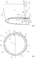
- an aircraft nacelle comprises at the front an air inlet 10 for channeling a flow of air towards a motorization 12.
- the longitudinal direction corresponds to the direction of the axis of the engine.
- a longitudinal plane is a plane that contains the axis of the engine.
- a transverse plane is a plane perpendicular to the axis of the engine.
- a radial direction is a direction perpendicular to the axis of the engine.
- front and back refer to the flow direction of the airflow in the nacelle. The front is an area where the air flow enters the basket and the back to an area where the air flow out of the nacelle.
- the air inlet 10 comprises a lip 14 which is extended inside the nacelle by a first conduit 16 of substantially circular sections, and outside the nacelle by an outer wall 18 of substantially circular sections.
- the motorization comprises a second duct 20 capable of being arranged in the extension of the inner duct 16.
- the first duct 16 is delimited by acoustic panels 22 juxtaposed over the entire circumference of the first duct 16 and which each comprise, in the radial direction, away from the axis of the motorization, a layer acoustically resistive 24, at least one cellular layer 26 and a reflective layer 28.
- the second duct 20 is also delimited by panels 30 juxtaposed all around the circumference of the second duct 20.
- the air inlet 10 is connected to the motor 12 by a connection which comprises a first annular flange 32 connected to the first duct 16 and a second annular collar 34 integral with the second duct 20.
- the two annular flanges 32 and 34 are clad against each other at a junction plane 36 substantially perpendicular to the longitudinal direction, and thus maintained by connecting elements 38, for example bolts or rivets, which pass through the annular flanges 32, 34 and whose axes are parallel to the longitudinal direction.
- the first annular flange 24 is made in one piece with the reflective layer 28 and forms an L with the reflective layer 28.
- the first flange Annular 32 and the reflective layer 28 are metallic.
- the first flange 32 corresponds to a first flange of a first L-shaped flange 40, the second flange of which is connected to the reflective layer 28.
- the first L-shaped flange 40 is metallic.
- the acoustic panel, and in particular the reflective layer 28, are made of composite material which makes it possible to reduce the embedded mass.
- the connection between the air inlet and the motorization comprises a first series of connecting elements 38 connecting the first and second annular flanges 32 and 34 and a second series of connecting elements 42 connecting the first L-shaped flange 40 and the acoustic panels 22 of the first duct 16.
- the panels 30 of the second duct 20 may also be made of composite material.
- the second annular flange 34 is integrated with a second metal L-flange.
- the connection between the air intake and the engine comprises a first series of connecting elements connecting the first and second L-shaped flanges, a second series of connecting elements connecting the first L-flange and the acoustic panels of the first conduit 16 and a third series of connecting elements connecting the second L-shaped flange and the panels 30 of the second conduit 20.
- the mass saving generated by the use of the composite materials for the panels 30 of the second conduit 20 is reduced due to the presence of three sets of connecting elements.
- the present invention proposes to overcome the disadvantages of the prior art.
- the invention makes it possible to eliminate the annular flanges and thus to reduce the on-board weight. According to another advantage, it is possible to connect the air inlet and the motor with only two sets of connecting elements and connecting strips made of composite material.
- the centering blades facilitate assembly because they allow to center the two ducts relative to each other before the establishment of connecting elements of the connecting blades.
- each second connecting element is a bolt which comprises a screw with a threaded rod and a head and a nut configured to be screwed onto the threaded rod, the connecting blade being interposed between an outer layer of the second conduit and the head of the screw, the nut being secured to the outer layer.
- connection comprises at least three centering blades distributed regularly around the first conduit, interposed between the connecting blades.
- the second end of the centering blades is curved towards the outside of the nacelle.
- the second end of the centering blades and / or an outer wall of the second conduit comprise a coating or are made of a material promoting the sliding of the centering blades on the surface of the outer wall of the second conduit.
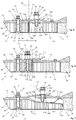
- an aircraft nacelle comprises, at the front, an air inlet 50 with a first duct 52 configured to channel an air flow in the direction a second conduit 54 of a motor 56.
- the first and second conduits 52 and 54 are end to end at a junction plane 58 substantially perpendicular to the longitudinal direction.
- the first duct 52 comprises at least one acoustic panel 60, generally several acoustic panels 60 juxtaposed on the circumference of the first duct 52.
- Each acoustic duct 60 comprises, in the radial direction, away from the axis of the motorization, a layer acoustically resistive 62, at least one alveolar layer 64 and a reflective layer 66.
- the second duct 54 comprises at least one panel 68, generally several panels 68 juxtaposed on the circumference of the second duct 54.
- the panels 68 are acoustic panels which each comprise, in the radial direction, away from the axis of the actuator, an acoustically resistive layer 70, at least one cellular layer 72 and a reflective layer 74.
- layer one both a layer and a plurality of superimposed layers.
- the second duct 54 surrounds the blower.
- Acoustic panels 62 are not more detailed because they are known to those skilled in the art. It is the same for the panels 68 of the second conduit 54 which are known under the name "Fan case" in English.
- each panel 62 or 68 comprises an outer wall, such as for example the reflective layer 66 or 74.
- each acoustic panel 60 comprises a 52E edge disposed in a transverse plane and each panel 68 comprises a edge 54E arranged in a transverse plane, the two edges 52E and 54E being pressed against each other at the junction plane 58 .
- the outer wall 74 of each panel 68 extends forwardly of the nacelle relative to the remainder of the panel 68. Its end 74E is positioned approximately in the junction plane 58. Thus, the outer wall 74 forms a housing 76 configured to receive the end 52E of the acoustic panels 60 which extend beyond the junction plane 58.
- the air intake 50 and the motor 56 are connected by a link 77 which comprises connecting blades 78 which each comprise a first junction zone 80 connected to the first conduit 52 of the air inlet 50 by at least one first connecting element 82 and a second junction zone 84 connected to the second conduit 54 of the motorization 56 by at least one second connecting element 86.
- the first and second connecting elements 82 and 86 each comprise a rod oriented in the radial direction and the first and second junction regions 80, 84 comprise for each first or second connecting element 82, 86 a passage orifice.
- a first or second connecting element 82 and 86 may be a bolt, a screw, a rivet or the like.
- blade By blade is meant a part which has a thickness (dimension taken in the radial direction) significantly smaller than its width (dimension taken along the circumference) and / or its length (dimension taken from the longitudinal direction). Naturally, a blade is configured to deform elastically in a preferred direction perpendicular to its width.
- Each connecting blade 78 is positioned to deform in operation elastically in the radial direction.
- one of its first and second junction zones 80, 84 can move in the radial direction relative to the other junction zone 80, 84, when a force oriented in the radial direction , not exceeding a given threshold, is exerted between the first and second conduits 52, 54.
- Each connecting blade 78 comprises a curved central portion 87, interposed between the first and second junction zones 80, 84 and eccentric with respect to at least one of the first and second junction zones 80, 84. This medial portion 87 promotes the deformation elastic of the connecting blade 78.
- the link 77 between the air inlet 50 and the motor 56 comprises several connecting blades 78 distributed over the entire circumference of the nacelle.
- the connecting strips 78 extend over identical angular sectors ⁇ to balance the forces.
- the nacelle comprises three connecting blades 78 which each extend over an angular sector of about 120 °.
- the distance L between the first and second junction zones 80, 84 may be longer or shorter as illustrated in the Figures 5 and 7 .
- the first connecting elements 82 are distributed, for example, in two rows which extend in different transverse planes, all around the circumference of the nacelle, the first connecting elements 82 being regularly distributed on each of the rows.
- Each first connecting element 82 is a bolt which comprises a screw 88 with a threaded rod 90 and a head 92 and a nut 94 configured to be screwed onto the threaded rod 90, the connecting blade 78 being interposed between the reflective layer 66 and the nut 94.
- the acoustic panel 60 comprises a tubular insert 96 to prevent the deformation of the cellular layer 64. As shown in FIGS.
- the tubular insert 96 is interposed between the head 92 of the screw 88 and the reflective layer 66, the head 92 of the screw 88 flush with the outer surface of the acoustically resistive layer 62.
- At least one first connecting element 82 comprises a deformable sheath in compression interposed between the nut 94 and the connecting blade 78.
- each second connecting element 86 is a bolt which comprises a screw 98 with a threaded rod 100 and a head 102 and a nut 104 configured to be screwed onto the threaded rod 100, the connecting blade 78 being interposed between the outer layer 74 and the head 102 of the screw 98.
- the nut 104 is secured to the outer layer 74 by any appropriate means such as for example using rivets 106.
- the screw 98 can be screwed without having need to hold the nut 104 with a tool.
- At least one second connecting element 86 comprises a deformable sleeve 89 in compression, interposed between the head 102 of the screw 98 and the connecting blade 78 which increases the capacity of the link 86 to accept the radial deformations, imposed by forces and / or displacements of the engine.
- the connecting blades 78 are fixed to the first duct 52 by means of the first connecting elements 82.
- the connecting blades 78 are then fitted around the second duct 54, and the second connecting elements 86 are then connected. place for connecting the connecting blades 78 and the second conduit 54.
- the second connecting elements 86 are put in place and tightened from outside the first and second conduits 52, 54.
- Each connecting blade 78 comprises an end 108, oriented towards the rear of the nacelle, curved towards the outside of the nacelle, to promote the fitting of the connecting blades 78 around the second duct 54.
- the link 77 comprises centering blades 110 having a first end 112 secured to the first conduit 52 by fastening elements 114 and a second end 115 configured to be engaged around second conduit 54 and which is not secured to the second conduit 54.
- Each centering blade 110 is configured to elastically deform in the radial direction. Thus, for each centering blade 110, the second end 115 can move in the radial direction relative to the first end 114.
- centering blades 110 make it possible to center the first duct 52 of the air inlet 50 with respect to the second duct 54 of the motorization 56 when the connecting strips 78 are fitted around the second duct 54, before attaching them to the second duct 54. leads 54.
- the link 77 comprises at least three centering blades 110 regularly distributed around the first conduit 52. As shown in FIG. figure 4 , the centering blades 110 are interposed between the connecting blades 78.
- the centering blades 110 have a width (dimension taken along the circumference) significantly lower than that of the connecting blades 78.
- the centering blades 110 have a width of between 2 and 10 cm.
- the second conduit 52 includes a notch in the outer wall 74 of the second conduit 54, which extends in the longitudinal direction and is configured to accommodate a centering blade 110.
- the width of each notch is substantially equal to the width of each centering blade 110 to prevent rotation of the first conduit 52 relative to the second conduit 54.
- the fastening elements 114 are distributed in two rows R1, R2 which extend in different transverse planes, over the entire circumference of the nacelle, the fastening elements 114 being regularly distributed on each of the rows.
- Each fastener 114 is a bolt that includes a screw 116 with a threaded rod 118 and a head 120 and a nut 122 configured to thread onto the threaded rod 118, the centering blade 110 being interposed between the reflective layer 66 and the nut 122.
- the acoustic panel 60 comprises a tubular insert 124 to prevent the deformation of the cellular layer 64.
- the tubular insert 124 is interposed between the head 120 of the screw 116 and the reflective layer 66, the head 120 of the screw 116 flush with the outer surface of the acoustically resistive layer 62.
- At least one fastening element 114 comprises a sleeve 126 deformable in compression, interposed between the nut 122 and the centering blade 110.
- the second end 115 of the centering blades 110 is curved towards the outside of the nacelle to promote the fitting of the centering blades 110 around the second conduit 54.
- the second end 115 of the centering blades 110 and / or the outer wall 74 of the second duct 54 comprise a coating or are made of a material promoting the sliding of the centering blades 110 on the surface of the outer wall 74 of the second duct 52.
- the outer wall 74 comprises a coating 128 of polytetrafluoroethylene.
- the connecting blades 78 and the centering blades 110 are made of metal or of composite material and made of a material giving them an ability to elastically deform in the radial direction.
- the link 77 comprises a centralizer 130 connected to the duct 52 which promotes the centering of the first duct 52 with respect to the second duct 54.
- the centralizer 130 comprises a plurality of elastic blades distributed over the periphery of the first duct 52.
Landscapes
- Engineering & Computer Science (AREA)
- Aviation & Aerospace Engineering (AREA)
- Chemical & Material Sciences (AREA)
- Combustion & Propulsion (AREA)
- Structures Of Non-Positive Displacement Pumps (AREA)
- Aerodynamic Tests, Hydrodynamic Tests, Wind Tunnels, And Water Tanks (AREA)
- Duct Arrangements (AREA)
- Tires In General (AREA)
- Wind Motors (AREA)
Applications Claiming Priority (1)
| Application Number | Priority Date | Filing Date | Title |
|---|---|---|---|
| FR1659895A FR3057544A1 (fr) | 2016-10-13 | 2016-10-13 | Nacelle d'aeronef comprenant une liaison entre une entree d'air et une motorisation |
Publications (2)
| Publication Number | Publication Date |
|---|---|
| EP3309075A1 true EP3309075A1 (de) | 2018-04-18 |
| EP3309075B1 EP3309075B1 (de) | 2019-12-04 |
Family
ID=57963266
Family Applications (1)
| Application Number | Title | Priority Date | Filing Date |
|---|---|---|---|
| EP17194655.1A Active EP3309075B1 (de) | 2016-10-13 | 2017-10-04 | Luftfahrzeuggondel, die eine verbindung zwischen einem lufteinlass und einer motorisierung umfasst |
Country Status (3)
| Country | Link |
|---|---|
| EP (1) | EP3309075B1 (de) |
| CN (1) | CN107933936B (de) |
| FR (1) | FR3057544A1 (de) |
Cited By (1)
| Publication number | Priority date | Publication date | Assignee | Title |
|---|---|---|---|---|
| EP3628842A1 (de) * | 2018-09-28 | 2020-04-01 | Airbus Operations | Einheit aus zwei nebeneinander angebrachten schalldämmpaneelen, bei der die paneele eine resistive oberfläche aufweisen, die sich bis zu einer stirnwand ausdehnt |
Families Citing this family (3)
| Publication number | Priority date | Publication date | Assignee | Title |
|---|---|---|---|---|
| FR3142454B1 (fr) * | 2022-11-28 | 2024-10-18 | Safran Nacelles | Entree d’air de nacelle de turboreacteur a montage ameliore |
| FR3164700A1 (fr) * | 2024-07-18 | 2026-01-23 | Safran Nacelles | Agencement pour aéronef comprenant un dispositif d’assemblage de deux pièces à deux couronnes emboitables pour un auto-ajustement radial |
| FR3164698A1 (fr) * | 2024-07-18 | 2026-01-23 | Safran Nacelles | Agencement pour aéronef comprenant un dispositif d’assemblage de deux pièces à cames d’appui radial |
Citations (9)
| Publication number | Priority date | Publication date | Assignee | Title |
|---|---|---|---|---|
| GB2259954A (en) * | 1991-09-27 | 1993-03-31 | Short Brothers Plc | Ducted fan turbine engine nozzle assembly |
| US5706648A (en) * | 1995-02-03 | 1998-01-13 | Aerospatiale Societe Nationale Industrielle | Sealing device between an air inlet and a fan frame of a turbofan engine |
| EP1013910A1 (de) * | 1998-12-21 | 2000-06-28 | Aerospatiale Matra | Struktur einer Flugzeugtriebwerksgondel |
| WO2011086281A1 (fr) * | 2009-12-22 | 2011-07-21 | Airbus Operations Sas | Nacelle incorporant un element de jonction entre une levre et un panneau d'attenuation acoustique |
| FR2960216A1 (fr) * | 2010-05-19 | 2011-11-25 | Aircelle Sa | Element d'aerodynamisme pour une nacelle d'aeronef |
| US20130098471A1 (en) * | 2011-10-03 | 2013-04-25 | Airbus Operations Sas | Aircraft nacelle comprising a hot air supply device for a panel combining acoustic and frost treatments |
| US20130121814A1 (en) * | 2010-06-29 | 2013-05-16 | Snecma | Turbojet engine nacelle |
| US20150007896A1 (en) * | 2012-03-29 | 2015-01-08 | Aircelle | Air inlet structure for a turbojet engine nacelle of laminar type |
| EP2998226A1 (de) * | 2014-09-18 | 2016-03-23 | The Boeing Company | Verfahren zum anbringen einer gondelstruktur zur minimierung von dauerbeanspruchung |
Family Cites Families (1)
| Publication number | Priority date | Publication date | Assignee | Title |
|---|---|---|---|---|
| FR2936223B1 (fr) * | 2008-09-23 | 2010-09-17 | Airbus France | Dispositif de liaison entre une entree d'air et une motorisation d'une nacelle d'aeronef |
-
2016
- 2016-10-13 FR FR1659895A patent/FR3057544A1/fr not_active Withdrawn
-
2017
- 2017-10-04 EP EP17194655.1A patent/EP3309075B1/de active Active
- 2017-10-10 CN CN201710936508.6A patent/CN107933936B/zh active Active
Patent Citations (9)
| Publication number | Priority date | Publication date | Assignee | Title |
|---|---|---|---|---|
| GB2259954A (en) * | 1991-09-27 | 1993-03-31 | Short Brothers Plc | Ducted fan turbine engine nozzle assembly |
| US5706648A (en) * | 1995-02-03 | 1998-01-13 | Aerospatiale Societe Nationale Industrielle | Sealing device between an air inlet and a fan frame of a turbofan engine |
| EP1013910A1 (de) * | 1998-12-21 | 2000-06-28 | Aerospatiale Matra | Struktur einer Flugzeugtriebwerksgondel |
| WO2011086281A1 (fr) * | 2009-12-22 | 2011-07-21 | Airbus Operations Sas | Nacelle incorporant un element de jonction entre une levre et un panneau d'attenuation acoustique |
| FR2960216A1 (fr) * | 2010-05-19 | 2011-11-25 | Aircelle Sa | Element d'aerodynamisme pour une nacelle d'aeronef |
| US20130121814A1 (en) * | 2010-06-29 | 2013-05-16 | Snecma | Turbojet engine nacelle |
| US20130098471A1 (en) * | 2011-10-03 | 2013-04-25 | Airbus Operations Sas | Aircraft nacelle comprising a hot air supply device for a panel combining acoustic and frost treatments |
| US20150007896A1 (en) * | 2012-03-29 | 2015-01-08 | Aircelle | Air inlet structure for a turbojet engine nacelle of laminar type |
| EP2998226A1 (de) * | 2014-09-18 | 2016-03-23 | The Boeing Company | Verfahren zum anbringen einer gondelstruktur zur minimierung von dauerbeanspruchung |
Cited By (3)
| Publication number | Priority date | Publication date | Assignee | Title |
|---|---|---|---|---|
| EP3628842A1 (de) * | 2018-09-28 | 2020-04-01 | Airbus Operations | Einheit aus zwei nebeneinander angebrachten schalldämmpaneelen, bei der die paneele eine resistive oberfläche aufweisen, die sich bis zu einer stirnwand ausdehnt |
| FR3086785A1 (fr) * | 2018-09-28 | 2020-04-03 | Airbus Operations | Ensemble comportant deux panneaux acoustiques juxtaposes dans lequel les panneaux comportent une face resistive qui s'etend jusqu'a une paroi d'extremite |
| US11066994B2 (en) | 2018-09-28 | 2021-07-20 | Airbus Operations (S.A.S.) | Assembly comprising two juxtaposed acoustic panels in which the panels comprise a resistive face which extends as far as an end wall |
Also Published As
| Publication number | Publication date |
|---|---|
| CN107933936B (zh) | 2022-09-13 |
| CN107933936A (zh) | 2018-04-20 |
| FR3057544A1 (fr) | 2018-04-20 |
| EP3309075B1 (de) | 2019-12-04 |
Similar Documents
| Publication | Publication Date | Title |
|---|---|---|
| EP3309075B1 (de) | Luftfahrzeuggondel, die eine verbindung zwischen einem lufteinlass und einer motorisierung umfasst | |
| EP2554822B1 (de) | Speziell angepasste Verbindungsvorrichtung zur Sicherstellung der Verbindung zwischen einem Lufteinlass und der Motorisierung einer Luftfahrzeuggondel | |
| EP2516271B1 (de) | Triebwerksgondel mit einem element zur verbindung einer umkantung mit einer schalldämmungsplatte | |
| EP4112476B1 (de) | Propeller- und elektromotorbaugruppe, die eine angepasste primärstruktur umfasst, und flugzeug, das mindestens eine solche baugruppe umfasst | |
| EP2742230A1 (de) | Auslasskonus für einen flugzeugturbodüsenmotor | |
| FR2998546A1 (fr) | Nacelle d'aeronef incorporant une liaison amelioree entre une entree d'air et une motorisation | |
| FR3075759A1 (fr) | Partie anterieure de nacelle d'un ensemble propulsif d'aeronef comportant un element amortisseur | |
| EP1355120B1 (de) | Vorrichtung zur provisorischen Verbindung und zum pyrotechnischen Trennen von zwei Elementen, ohne Bruch | |
| EP2554480B1 (de) | Speziell angepasste Verbindungsvorrichtung zur Sicherstellung der Verbindung zwischen einem Lufteinlass und der Motorisierung einer Luftfahrzeuggondel | |
| FR2998547A1 (fr) | Nacelle d'aeronef comprenant une liaison deformable entre une entree d'air et une motorisation | |
| FR3099915A1 (fr) | Partie antérieure de nacelle d’un ensemble propulsif d’aéronef dont la lèvre d’entrée d’air est liée au panneau extérieur par emboitement | |
| EP3309078B1 (de) | Luftfahrzeuggondel, die eine verbindung zwischen einer luftleitung und einer motorisierungsleitung umfasst | |
| FR3083214A1 (fr) | Nacelle d'un ensemble propulsif d'aeronef comportant une pluralite d'elements amortisseurs entre une partie avant et une partie principale, et ensemble propulsif d'aeronef associe | |
| FR3003233A1 (fr) | Panneau de voilure pour aeronef | |
| FR3055885A1 (fr) | Nacelle d'aeronef comprenant une liaison entre une entree d'air et une motorisation qui comporte une bride | |
| EP2554481B1 (de) | Speziell angepasste Verbindungsvorrichtung zur Sicherstellung der Verbindung zwischen einem Lufteinlass und der Motorisierung einer Luftfahrzeuggondel | |
| EP3778382A1 (de) | Frontteil einer gondel einer antriebsgruppe eines luftfahrzeugs, dessen frontrahmen mit einer aussenwand verbunden ist, ohne diese zu durchdringen | |
| FR2966125A1 (fr) | Ensemble d'accrochage d'une suspension d'un ensemble propulsif d'aeronef | |
| FR3055922A1 (fr) | Ensemble propulsif d'aeronef comprenant une liaison entre une entree d'air et une motorisation | |
| FR3137367A1 (fr) | Structure en treillis renforcée et aéronef comprenant au moins une telle structure | |
| EP4173961B1 (de) | Flugzeuggondel mit einer verbindung zwischen durchgängen mit nach innen gerichteten flanschen und flugzeug mit mindestens einer solchen gondel | |
| EP3575208A1 (de) | Flugzeug mit aerodynamischer wand und mindestens einem wirbelerzeuger | |
| FR2994888A1 (fr) | Assemblage de deux pieces en materiau composite | |
| EP2554479B1 (de) | Speziell angepasste Verbindungsvorrichtung zur Sicherstellung der Verbindung zwischen einem Lufteinlass und der Motorisierung einer Luftfahrzeuggondel | |
| EP3696081B1 (de) | Verfahren zum zusammenbau von zwei teilen, und verfahren zum zusammenbau von zwei abschnitten eines luftfahrzeugs |
Legal Events
| Date | Code | Title | Description |
|---|---|---|---|
| PUAI | Public reference made under article 153(3) epc to a published international application that has entered the european phase |
Free format text: ORIGINAL CODE: 0009012 |
|
| STAA | Information on the status of an ep patent application or granted ep patent |
Free format text: STATUS: THE APPLICATION HAS BEEN PUBLISHED |
|
| AK | Designated contracting states |
Kind code of ref document: A1 Designated state(s): AL AT BE BG CH CY CZ DE DK EE ES FI FR GB GR HR HU IE IS IT LI LT LU LV MC MK MT NL NO PL PT RO RS SE SI SK SM TR |
|
| AX | Request for extension of the european patent |
Extension state: BA ME |
|
| STAA | Information on the status of an ep patent application or granted ep patent |
Free format text: STATUS: REQUEST FOR EXAMINATION WAS MADE |
|
| 17P | Request for examination filed |
Effective date: 20181008 |
|
| RBV | Designated contracting states (corrected) |
Designated state(s): AL AT BE BG CH CY CZ DE DK EE ES FI FR GB GR HR HU IE IS IT LI LT LU LV MC MK MT NL NO PL PT RO RS SE SI SK SM TR |
|
| STAA | Information on the status of an ep patent application or granted ep patent |
Free format text: STATUS: EXAMINATION IS IN PROGRESS |
|
| 17Q | First examination report despatched |
Effective date: 20190219 |
|
| RIC1 | Information provided on ipc code assigned before grant |
Ipc: B64D 29/00 20060101ALN20190716BHEP Ipc: B64D 33/02 20060101AFI20190716BHEP |
|
| GRAP | Despatch of communication of intention to grant a patent |
Free format text: ORIGINAL CODE: EPIDOSNIGR1 |
|
| STAA | Information on the status of an ep patent application or granted ep patent |
Free format text: STATUS: GRANT OF PATENT IS INTENDED |
|
| RIC1 | Information provided on ipc code assigned before grant |
Ipc: B64D 29/00 20060101ALN20190731BHEP Ipc: B64D 33/02 20060101AFI20190731BHEP |
|
| GRAS | Grant fee paid |
Free format text: ORIGINAL CODE: EPIDOSNIGR3 |
|
| INTG | Intention to grant announced |
Effective date: 20190903 |
|
| GRAA | (expected) grant |
Free format text: ORIGINAL CODE: 0009210 |
|
| STAA | Information on the status of an ep patent application or granted ep patent |
Free format text: STATUS: THE PATENT HAS BEEN GRANTED |
|
| AK | Designated contracting states |
Kind code of ref document: B1 Designated state(s): AL AT BE BG CH CY CZ DE DK EE ES FI FR GB GR HR HU IE IS IT LI LT LU LV MC MK MT NL NO PL PT RO RS SE SI SK SM TR |
|
| REG | Reference to a national code |
Ref country code: GB Ref legal event code: FG4D Free format text: NOT ENGLISH |
|
| REG | Reference to a national code |
Ref country code: CH Ref legal event code: EP |
|
| REG | Reference to a national code |
Ref country code: AT Ref legal event code: REF Ref document number: 1209089 Country of ref document: AT Kind code of ref document: T Effective date: 20191215 |
|
| REG | Reference to a national code |
Ref country code: DE Ref legal event code: R096 Ref document number: 602017009285 Country of ref document: DE |
|
| REG | Reference to a national code |
Ref country code: IE Ref legal event code: FG4D Free format text: LANGUAGE OF EP DOCUMENT: FRENCH |
|
| REG | Reference to a national code |
Ref country code: NL Ref legal event code: MP Effective date: 20191204 |
|
| REG | Reference to a national code |
Ref country code: LT Ref legal event code: MG4D |
|
| PG25 | Lapsed in a contracting state [announced via postgrant information from national office to epo] |
Ref country code: GR Free format text: LAPSE BECAUSE OF FAILURE TO SUBMIT A TRANSLATION OF THE DESCRIPTION OR TO PAY THE FEE WITHIN THE PRESCRIBED TIME-LIMIT Effective date: 20200305 Ref country code: NO Free format text: LAPSE BECAUSE OF FAILURE TO SUBMIT A TRANSLATION OF THE DESCRIPTION OR TO PAY THE FEE WITHIN THE PRESCRIBED TIME-LIMIT Effective date: 20200304 Ref country code: SE Free format text: LAPSE BECAUSE OF FAILURE TO SUBMIT A TRANSLATION OF THE DESCRIPTION OR TO PAY THE FEE WITHIN THE PRESCRIBED TIME-LIMIT Effective date: 20191204 Ref country code: LV Free format text: LAPSE BECAUSE OF FAILURE TO SUBMIT A TRANSLATION OF THE DESCRIPTION OR TO PAY THE FEE WITHIN THE PRESCRIBED TIME-LIMIT Effective date: 20191204 Ref country code: BG Free format text: LAPSE BECAUSE OF FAILURE TO SUBMIT A TRANSLATION OF THE DESCRIPTION OR TO PAY THE FEE WITHIN THE PRESCRIBED TIME-LIMIT Effective date: 20200304 Ref country code: LT Free format text: LAPSE BECAUSE OF FAILURE TO SUBMIT A TRANSLATION OF THE DESCRIPTION OR TO PAY THE FEE WITHIN THE PRESCRIBED TIME-LIMIT Effective date: 20191204 Ref country code: FI Free format text: LAPSE BECAUSE OF FAILURE TO SUBMIT A TRANSLATION OF THE DESCRIPTION OR TO PAY THE FEE WITHIN THE PRESCRIBED TIME-LIMIT Effective date: 20191204 |
|
| PG25 | Lapsed in a contracting state [announced via postgrant information from national office to epo] |
Ref country code: RS Free format text: LAPSE BECAUSE OF FAILURE TO SUBMIT A TRANSLATION OF THE DESCRIPTION OR TO PAY THE FEE WITHIN THE PRESCRIBED TIME-LIMIT Effective date: 20191204 Ref country code: HR Free format text: LAPSE BECAUSE OF FAILURE TO SUBMIT A TRANSLATION OF THE DESCRIPTION OR TO PAY THE FEE WITHIN THE PRESCRIBED TIME-LIMIT Effective date: 20191204 |
|
| PG25 | Lapsed in a contracting state [announced via postgrant information from national office to epo] |
Ref country code: AL Free format text: LAPSE BECAUSE OF FAILURE TO SUBMIT A TRANSLATION OF THE DESCRIPTION OR TO PAY THE FEE WITHIN THE PRESCRIBED TIME-LIMIT Effective date: 20191204 |
|
| PG25 | Lapsed in a contracting state [announced via postgrant information from national office to epo] |
Ref country code: CZ Free format text: LAPSE BECAUSE OF FAILURE TO SUBMIT A TRANSLATION OF THE DESCRIPTION OR TO PAY THE FEE WITHIN THE PRESCRIBED TIME-LIMIT Effective date: 20191204 Ref country code: RO Free format text: LAPSE BECAUSE OF FAILURE TO SUBMIT A TRANSLATION OF THE DESCRIPTION OR TO PAY THE FEE WITHIN THE PRESCRIBED TIME-LIMIT Effective date: 20191204 Ref country code: EE Free format text: LAPSE BECAUSE OF FAILURE TO SUBMIT A TRANSLATION OF THE DESCRIPTION OR TO PAY THE FEE WITHIN THE PRESCRIBED TIME-LIMIT Effective date: 20191204 Ref country code: PT Free format text: LAPSE BECAUSE OF FAILURE TO SUBMIT A TRANSLATION OF THE DESCRIPTION OR TO PAY THE FEE WITHIN THE PRESCRIBED TIME-LIMIT Effective date: 20200429 Ref country code: ES Free format text: LAPSE BECAUSE OF FAILURE TO SUBMIT A TRANSLATION OF THE DESCRIPTION OR TO PAY THE FEE WITHIN THE PRESCRIBED TIME-LIMIT Effective date: 20191204 Ref country code: NL Free format text: LAPSE BECAUSE OF FAILURE TO SUBMIT A TRANSLATION OF THE DESCRIPTION OR TO PAY THE FEE WITHIN THE PRESCRIBED TIME-LIMIT Effective date: 20191204 |
|
| PG25 | Lapsed in a contracting state [announced via postgrant information from national office to epo] |
Ref country code: IS Free format text: LAPSE BECAUSE OF FAILURE TO SUBMIT A TRANSLATION OF THE DESCRIPTION OR TO PAY THE FEE WITHIN THE PRESCRIBED TIME-LIMIT Effective date: 20200404 Ref country code: SK Free format text: LAPSE BECAUSE OF FAILURE TO SUBMIT A TRANSLATION OF THE DESCRIPTION OR TO PAY THE FEE WITHIN THE PRESCRIBED TIME-LIMIT Effective date: 20191204 Ref country code: SM Free format text: LAPSE BECAUSE OF FAILURE TO SUBMIT A TRANSLATION OF THE DESCRIPTION OR TO PAY THE FEE WITHIN THE PRESCRIBED TIME-LIMIT Effective date: 20191204 |
|
| REG | Reference to a national code |
Ref country code: DE Ref legal event code: R097 Ref document number: 602017009285 Country of ref document: DE |
|
| REG | Reference to a national code |
Ref country code: AT Ref legal event code: MK05 Ref document number: 1209089 Country of ref document: AT Kind code of ref document: T Effective date: 20191204 |
|
| PLBE | No opposition filed within time limit |
Free format text: ORIGINAL CODE: 0009261 |
|
| STAA | Information on the status of an ep patent application or granted ep patent |
Free format text: STATUS: NO OPPOSITION FILED WITHIN TIME LIMIT |
|
| PG25 | Lapsed in a contracting state [announced via postgrant information from national office to epo] |
Ref country code: DK Free format text: LAPSE BECAUSE OF FAILURE TO SUBMIT A TRANSLATION OF THE DESCRIPTION OR TO PAY THE FEE WITHIN THE PRESCRIBED TIME-LIMIT Effective date: 20191204 |
|
| 26N | No opposition filed |
Effective date: 20200907 |
|
| PG25 | Lapsed in a contracting state [announced via postgrant information from national office to epo] |
Ref country code: SI Free format text: LAPSE BECAUSE OF FAILURE TO SUBMIT A TRANSLATION OF THE DESCRIPTION OR TO PAY THE FEE WITHIN THE PRESCRIBED TIME-LIMIT Effective date: 20191204 Ref country code: AT Free format text: LAPSE BECAUSE OF FAILURE TO SUBMIT A TRANSLATION OF THE DESCRIPTION OR TO PAY THE FEE WITHIN THE PRESCRIBED TIME-LIMIT Effective date: 20191204 Ref country code: PL Free format text: LAPSE BECAUSE OF FAILURE TO SUBMIT A TRANSLATION OF THE DESCRIPTION OR TO PAY THE FEE WITHIN THE PRESCRIBED TIME-LIMIT Effective date: 20191204 |
|
| PG25 | Lapsed in a contracting state [announced via postgrant information from national office to epo] |
Ref country code: IT Free format text: LAPSE BECAUSE OF FAILURE TO SUBMIT A TRANSLATION OF THE DESCRIPTION OR TO PAY THE FEE WITHIN THE PRESCRIBED TIME-LIMIT Effective date: 20191204 |
|
| REG | Reference to a national code |
Ref country code: CH Ref legal event code: PL |
|
| PG25 | Lapsed in a contracting state [announced via postgrant information from national office to epo] |
Ref country code: LU Free format text: LAPSE BECAUSE OF NON-PAYMENT OF DUE FEES Effective date: 20201004 Ref country code: MC Free format text: LAPSE BECAUSE OF FAILURE TO SUBMIT A TRANSLATION OF THE DESCRIPTION OR TO PAY THE FEE WITHIN THE PRESCRIBED TIME-LIMIT Effective date: 20191204 |
|
| REG | Reference to a national code |
Ref country code: BE Ref legal event code: MM Effective date: 20201031 |
|
| PG25 | Lapsed in a contracting state [announced via postgrant information from national office to epo] |
Ref country code: LI Free format text: LAPSE BECAUSE OF NON-PAYMENT OF DUE FEES Effective date: 20201031 Ref country code: BE Free format text: LAPSE BECAUSE OF NON-PAYMENT OF DUE FEES Effective date: 20201031 Ref country code: CH Free format text: LAPSE BECAUSE OF NON-PAYMENT OF DUE FEES Effective date: 20201031 |
|
| PG25 | Lapsed in a contracting state [announced via postgrant information from national office to epo] |
Ref country code: IE Free format text: LAPSE BECAUSE OF NON-PAYMENT OF DUE FEES Effective date: 20201004 |
|
| PG25 | Lapsed in a contracting state [announced via postgrant information from national office to epo] |
Ref country code: TR Free format text: LAPSE BECAUSE OF FAILURE TO SUBMIT A TRANSLATION OF THE DESCRIPTION OR TO PAY THE FEE WITHIN THE PRESCRIBED TIME-LIMIT Effective date: 20191204 Ref country code: MT Free format text: LAPSE BECAUSE OF FAILURE TO SUBMIT A TRANSLATION OF THE DESCRIPTION OR TO PAY THE FEE WITHIN THE PRESCRIBED TIME-LIMIT Effective date: 20191204 Ref country code: CY Free format text: LAPSE BECAUSE OF FAILURE TO SUBMIT A TRANSLATION OF THE DESCRIPTION OR TO PAY THE FEE WITHIN THE PRESCRIBED TIME-LIMIT Effective date: 20191204 |
|
| PG25 | Lapsed in a contracting state [announced via postgrant information from national office to epo] |
Ref country code: MK Free format text: LAPSE BECAUSE OF FAILURE TO SUBMIT A TRANSLATION OF THE DESCRIPTION OR TO PAY THE FEE WITHIN THE PRESCRIBED TIME-LIMIT Effective date: 20191204 |
|
| PGFP | Annual fee paid to national office [announced via postgrant information from national office to epo] |
Ref country code: DE Payment date: 20231020 Year of fee payment: 7 |
|
| REG | Reference to a national code |
Ref country code: DE Ref legal event code: R119 Ref document number: 602017009285 Country of ref document: DE |
|
| PG25 | Lapsed in a contracting state [announced via postgrant information from national office to epo] |
Ref country code: DE Free format text: LAPSE BECAUSE OF NON-PAYMENT OF DUE FEES Effective date: 20250501 |
|
| PGFP | Annual fee paid to national office [announced via postgrant information from national office to epo] |
Ref country code: GB Payment date: 20251024 Year of fee payment: 9 |
|
| PGFP | Annual fee paid to national office [announced via postgrant information from national office to epo] |
Ref country code: FR Payment date: 20251030 Year of fee payment: 9 |