EP3309402B1 - Procédé de détermination d'un débit cible d'un système de pompage - Google Patents
Procédé de détermination d'un débit cible d'un système de pompage Download PDFInfo
- Publication number
- EP3309402B1 EP3309402B1 EP17192909.4A EP17192909A EP3309402B1 EP 3309402 B1 EP3309402 B1 EP 3309402B1 EP 17192909 A EP17192909 A EP 17192909A EP 3309402 B1 EP3309402 B1 EP 3309402B1
- Authority
- EP
- European Patent Office
- Prior art keywords
- control
- conveying capacity
- temperature
- conveying
- pumping system
- Prior art date
- Legal status (The legal status is an assumption and is not a legal conclusion. Google has not performed a legal analysis and makes no representation as to the accuracy of the status listed.)
- Active
Links
Images

Classifications
-
- B—PERFORMING OPERATIONS; TRANSPORTING
- B29—WORKING OF PLASTICS; WORKING OF SUBSTANCES IN A PLASTIC STATE IN GENERAL
- B29C—SHAPING OR JOINING OF PLASTICS; SHAPING OF MATERIAL IN A PLASTIC STATE, NOT OTHERWISE PROVIDED FOR; AFTER-TREATMENT OF THE SHAPED PRODUCTS, e.g. REPAIRING
- B29C45/00—Injection moulding, i.e. forcing the required volume of moulding material through a nozzle into a closed mould; Apparatus therefor
- B29C45/17—Component parts, details or accessories; Auxiliary operations
- B29C45/72—Heating or cooling
- B29C45/73—Heating or cooling of the mould
- B29C45/7306—Control circuits therefor
-
- F—MECHANICAL ENGINEERING; LIGHTING; HEATING; WEAPONS; BLASTING
- F04—POSITIVE - DISPLACEMENT MACHINES FOR LIQUIDS; PUMPS FOR LIQUIDS OR ELASTIC FLUIDS
- F04D—NON-POSITIVE-DISPLACEMENT PUMPS
- F04D15/00—Control, e.g. regulation, of pumps, pumping installations or systems
- F04D15/0005—Control, e.g. regulation, of pumps, pumping installations or systems by using valves
- F04D15/0022—Control, e.g. regulation, of pumps, pumping installations or systems by using valves throttling valves or valves varying the pump inlet opening or the outlet opening
-
- B—PERFORMING OPERATIONS; TRANSPORTING
- B29—WORKING OF PLASTICS; WORKING OF SUBSTANCES IN A PLASTIC STATE IN GENERAL
- B29C—SHAPING OR JOINING OF PLASTICS; SHAPING OF MATERIAL IN A PLASTIC STATE, NOT OTHERWISE PROVIDED FOR; AFTER-TREATMENT OF THE SHAPED PRODUCTS, e.g. REPAIRING
- B29C35/00—Heating, cooling or curing, e.g. crosslinking or vulcanising; Apparatus therefor
- B29C35/02—Heating or curing, e.g. crosslinking or vulcanizing during moulding, e.g. in a mould
- B29C35/0288—Controlling heating or curing of polymers during moulding, e.g. by measuring temperatures or properties of the polymer and regulating the process
- B29C35/0294—Controlling heating or curing of polymers during moulding, e.g. by measuring temperatures or properties of the polymer and regulating the process using tempering units for temperature control of moulds or cores
-
- B—PERFORMING OPERATIONS; TRANSPORTING
- B29—WORKING OF PLASTICS; WORKING OF SUBSTANCES IN A PLASTIC STATE IN GENERAL
- B29C—SHAPING OR JOINING OF PLASTICS; SHAPING OF MATERIAL IN A PLASTIC STATE, NOT OTHERWISE PROVIDED FOR; AFTER-TREATMENT OF THE SHAPED PRODUCTS, e.g. REPAIRING
- B29C45/00—Injection moulding, i.e. forcing the required volume of moulding material through a nozzle into a closed mould; Apparatus therefor
- B29C45/17—Component parts, details or accessories; Auxiliary operations
- B29C45/76—Measuring, controlling or regulating
- B29C45/78—Measuring, controlling or regulating of temperature
-
- F—MECHANICAL ENGINEERING; LIGHTING; HEATING; WEAPONS; BLASTING
- F04—POSITIVE - DISPLACEMENT MACHINES FOR LIQUIDS; PUMPS FOR LIQUIDS OR ELASTIC FLUIDS
- F04B—POSITIVE-DISPLACEMENT MACHINES FOR LIQUIDS; PUMPS
- F04B49/00—Control, e.g. of pump delivery, or pump pressure of, or safety measures for, machines, pumps, or pumping installations, not otherwise provided for, or of interest apart from, groups F04B1/00 - F04B47/00
- F04B49/06—Control using electricity
- F04B49/065—Control using electricity and making use of computers
-
- B—PERFORMING OPERATIONS; TRANSPORTING
- B29—WORKING OF PLASTICS; WORKING OF SUBSTANCES IN A PLASTIC STATE IN GENERAL
- B29C—SHAPING OR JOINING OF PLASTICS; SHAPING OF MATERIAL IN A PLASTIC STATE, NOT OTHERWISE PROVIDED FOR; AFTER-TREATMENT OF THE SHAPED PRODUCTS, e.g. REPAIRING
- B29C33/00—Moulds or cores; Details thereof or accessories therefor
- B29C33/02—Moulds or cores; Details thereof or accessories therefor with incorporated heating or cooling means
- B29C33/04—Moulds or cores; Details thereof or accessories therefor with incorporated heating or cooling means using liquids, gas or steam
-
- B—PERFORMING OPERATIONS; TRANSPORTING
- B29—WORKING OF PLASTICS; WORKING OF SUBSTANCES IN A PLASTIC STATE IN GENERAL
- B29C—SHAPING OR JOINING OF PLASTICS; SHAPING OF MATERIAL IN A PLASTIC STATE, NOT OTHERWISE PROVIDED FOR; AFTER-TREATMENT OF THE SHAPED PRODUCTS, e.g. REPAIRING
- B29C35/00—Heating, cooling or curing, e.g. crosslinking or vulcanising; Apparatus therefor
- B29C35/007—Tempering units for temperature control of moulds or cores, e.g. comprising heat exchangers, controlled valves, temperature-controlled circuits for fluids
-
- B—PERFORMING OPERATIONS; TRANSPORTING
- B29—WORKING OF PLASTICS; WORKING OF SUBSTANCES IN A PLASTIC STATE IN GENERAL
- B29C—SHAPING OR JOINING OF PLASTICS; SHAPING OF MATERIAL IN A PLASTIC STATE, NOT OTHERWISE PROVIDED FOR; AFTER-TREATMENT OF THE SHAPED PRODUCTS, e.g. REPAIRING
- B29C35/00—Heating, cooling or curing, e.g. crosslinking or vulcanising; Apparatus therefor
- B29C35/16—Cooling
-
- B—PERFORMING OPERATIONS; TRANSPORTING
- B29—WORKING OF PLASTICS; WORKING OF SUBSTANCES IN A PLASTIC STATE IN GENERAL
- B29C—SHAPING OR JOINING OF PLASTICS; SHAPING OF MATERIAL IN A PLASTIC STATE, NOT OTHERWISE PROVIDED FOR; AFTER-TREATMENT OF THE SHAPED PRODUCTS, e.g. REPAIRING
- B29C45/00—Injection moulding, i.e. forcing the required volume of moulding material through a nozzle into a closed mould; Apparatus therefor
- B29C45/17—Component parts, details or accessories; Auxiliary operations
- B29C45/72—Heating or cooling
- B29C45/73—Heating or cooling of the mould
-
- B—PERFORMING OPERATIONS; TRANSPORTING
- B29—WORKING OF PLASTICS; WORKING OF SUBSTANCES IN A PLASTIC STATE IN GENERAL
- B29C—SHAPING OR JOINING OF PLASTICS; SHAPING OF MATERIAL IN A PLASTIC STATE, NOT OTHERWISE PROVIDED FOR; AFTER-TREATMENT OF THE SHAPED PRODUCTS, e.g. REPAIRING
- B29C45/00—Injection moulding, i.e. forcing the required volume of moulding material through a nozzle into a closed mould; Apparatus therefor
- B29C45/17—Component parts, details or accessories; Auxiliary operations
- B29C45/72—Heating or cooling
- B29C45/73—Heating or cooling of the mould
- B29C45/7312—Construction of heating or cooling fluid flow channels
-
- B—PERFORMING OPERATIONS; TRANSPORTING
- B29—WORKING OF PLASTICS; WORKING OF SUBSTANCES IN A PLASTIC STATE IN GENERAL
- B29C—SHAPING OR JOINING OF PLASTICS; SHAPING OF MATERIAL IN A PLASTIC STATE, NOT OTHERWISE PROVIDED FOR; AFTER-TREATMENT OF THE SHAPED PRODUCTS, e.g. REPAIRING
- B29C45/00—Injection moulding, i.e. forcing the required volume of moulding material through a nozzle into a closed mould; Apparatus therefor
- B29C45/17—Component parts, details or accessories; Auxiliary operations
- B29C45/76—Measuring, controlling or regulating
-
- F—MECHANICAL ENGINEERING; LIGHTING; HEATING; WEAPONS; BLASTING
- F04—POSITIVE - DISPLACEMENT MACHINES FOR LIQUIDS; PUMPS FOR LIQUIDS OR ELASTIC FLUIDS
- F04D—NON-POSITIVE-DISPLACEMENT PUMPS
- F04D13/00—Pumping installations or systems
- F04D13/02—Units comprising pumps and their driving means
- F04D13/06—Units comprising pumps and their driving means the pump being electrically driven
- F04D13/0686—Mechanical details of the pump control unit
-
- F—MECHANICAL ENGINEERING; LIGHTING; HEATING; WEAPONS; BLASTING
- F04—POSITIVE - DISPLACEMENT MACHINES FOR LIQUIDS; PUMPS FOR LIQUIDS OR ELASTIC FLUIDS
- F04D—NON-POSITIVE-DISPLACEMENT PUMPS
- F04D15/00—Control, e.g. regulation, of pumps, pumping installations or systems
- F04D15/0088—Testing machines
-
- G—PHYSICS
- G05—CONTROLLING; REGULATING
- G05D—SYSTEMS FOR CONTROLLING OR REGULATING NON-ELECTRIC VARIABLES
- G05D23/00—Control of temperature
- G05D23/19—Control of temperature characterised by the use of electric means
-
- G—PHYSICS
- G05—CONTROLLING; REGULATING
- G05D—SYSTEMS FOR CONTROLLING OR REGULATING NON-ELECTRIC VARIABLES
- G05D7/00—Control of flow
- G05D7/06—Control of flow characterised by the use of electric means
- G05D7/0617—Control of flow characterised by the use of electric means specially adapted for fluid materials
-
- B—PERFORMING OPERATIONS; TRANSPORTING
- B29—WORKING OF PLASTICS; WORKING OF SUBSTANCES IN A PLASTIC STATE IN GENERAL
- B29C—SHAPING OR JOINING OF PLASTICS; SHAPING OF MATERIAL IN A PLASTIC STATE, NOT OTHERWISE PROVIDED FOR; AFTER-TREATMENT OF THE SHAPED PRODUCTS, e.g. REPAIRING
- B29C35/00—Heating, cooling or curing, e.g. crosslinking or vulcanising; Apparatus therefor
- B29C35/16—Cooling
- B29C2035/1616—Cooling using liquids
-
- B—PERFORMING OPERATIONS; TRANSPORTING
- B29—WORKING OF PLASTICS; WORKING OF SUBSTANCES IN A PLASTIC STATE IN GENERAL
- B29C—SHAPING OR JOINING OF PLASTICS; SHAPING OF MATERIAL IN A PLASTIC STATE, NOT OTHERWISE PROVIDED FOR; AFTER-TREATMENT OF THE SHAPED PRODUCTS, e.g. REPAIRING
- B29C2945/00—Indexing scheme relating to injection moulding, i.e. forcing the required volume of moulding material through a nozzle into a closed mould
- B29C2945/76—Measuring, controlling or regulating
- B29C2945/76003—Measured parameter
- B29C2945/7604—Temperature
-
- B—PERFORMING OPERATIONS; TRANSPORTING
- B29—WORKING OF PLASTICS; WORKING OF SUBSTANCES IN A PLASTIC STATE IN GENERAL
- B29C—SHAPING OR JOINING OF PLASTICS; SHAPING OF MATERIAL IN A PLASTIC STATE, NOT OTHERWISE PROVIDED FOR; AFTER-TREATMENT OF THE SHAPED PRODUCTS, e.g. REPAIRING
- B29C2945/00—Indexing scheme relating to injection moulding, i.e. forcing the required volume of moulding material through a nozzle into a closed mould
- B29C2945/76—Measuring, controlling or regulating
- B29C2945/76003—Measured parameter
- B29C2945/76056—Flow rate
-
- B—PERFORMING OPERATIONS; TRANSPORTING
- B29—WORKING OF PLASTICS; WORKING OF SUBSTANCES IN A PLASTIC STATE IN GENERAL
- B29C—SHAPING OR JOINING OF PLASTICS; SHAPING OF MATERIAL IN A PLASTIC STATE, NOT OTHERWISE PROVIDED FOR; AFTER-TREATMENT OF THE SHAPED PRODUCTS, e.g. REPAIRING
- B29C2945/00—Indexing scheme relating to injection moulding, i.e. forcing the required volume of moulding material through a nozzle into a closed mould
- B29C2945/76—Measuring, controlling or regulating
- B29C2945/76494—Controlled parameter
- B29C2945/76531—Temperature
-
- B—PERFORMING OPERATIONS; TRANSPORTING
- B29—WORKING OF PLASTICS; WORKING OF SUBSTANCES IN A PLASTIC STATE IN GENERAL
- B29C—SHAPING OR JOINING OF PLASTICS; SHAPING OF MATERIAL IN A PLASTIC STATE, NOT OTHERWISE PROVIDED FOR; AFTER-TREATMENT OF THE SHAPED PRODUCTS, e.g. REPAIRING
- B29C2945/00—Indexing scheme relating to injection moulding, i.e. forcing the required volume of moulding material through a nozzle into a closed mould
- B29C2945/76—Measuring, controlling or regulating
- B29C2945/76494—Controlled parameter
- B29C2945/76545—Flow rate
Definitions
- the present invention relates to a method for finding a target delivery rate of a pump system having at least one pump for delivering a temperature control medium through at least one temperature control channel of a molding tool by means of the at least one pump.
- the present invention also relates to a pump system for conveying a temperature control medium through at least one temperature control channel of a molding tool with the features of the preamble of claim 9 and claim 10, respectively.
- Molding tools that are used in molding machines must in many cases be temperature-controlled, that is to say cooled or heated in a targeted manner.
- This temperature control can be achieved by conveying a temperature control medium through corresponding temperature control channels that penetrate the molding tool.
- several temperature control channels are used and it is known to regulate the temperature control volume flow through the individual temperature control channels, for example according to the volume flow rate, the pressure drop, the temperature difference or the like.
- the object of the invention is therefore to provide a method and a device which allow the target delivery rate to be determined in a simplified manner.
- the target delivery rate can be determined on the basis of a starting delivery rate that is too high or too low for the at least one temperature control volume flow.
- the target delivery rate can be determined on the basis of a starting delivery rate that is too high or too low for the at least one temperature control volume flow.
- An important aspect of the invention consists in the knowledge that the pump system can be controlled independently of a regulation of the temperature control volume flow in such a way that an optimized value for a target delivery rate of the pump system can be found. As a result, the control of the pump system can be completely decoupled from a control loop for the at least one temperature control volume flow, which obviously simplifies the control or regulation of the pump system.
- a value range for the temperature control volume flow that the temperature control volume flow must not leave in order to be considered constant can be used. This range of values can be given, for example, by a mean value and limit values for the deviation therefrom.
- This criterion can also be used to determine the constancy of the flow rate.
- the regulation according to method step a) or the measurement of the flow rate according to method step b) can take place continuously, that is to say continuously, or "pulsed", that is to say at regular or irregular intervals.
- process step c) a control according to process step a) and / or a measurement according to process step b) is carried out in order to be able to detect a possible change in the flow rate.
- Process step d) including i and ii is carried out after process step c).
- water or oil can be used as the temperature control medium.
- the delivery rate of one or more pumps in the pump system can be reduced.
- one or more pumps of the pump system can be switched off completely.
- the pump system can be operated with this target delivery rate.
- the at least one temperature control volume flow itself can be used as a control variable for regulating the at least one temperature control volume flow.
- temperature differences, return temperatures, amounts of heat, flow velocities and similar quantities that are physically and / or mathematically related to the temperature control volume flow can be used.
- the sensor can be designed, for example, as a volume flow sensor.
- upstream and downstream temperature sensors, pressure sensors or sensors for variables that are physically and / or mathematically related to these variables can be used.
- the measurement of the delivery flow of the pump system is carried out as part of the regulation of the at least one temperature control volume flow. In terms of construction, this alternative is less complex, since no additional volume flow sensors are necessary.
- a combination of the measurement of the delivery flow by own sensors or sensors for regulating the temperature control volume flow, for example by averaging or the like, can also be advantageous.
- method steps c) and d) including i. and ii. be carried out several times, the target delivery rate from the previous implementation being used as the starting delivery rate.
- the effect of the Invention are reinforced and a more energy-saving target delivery rate can be found.
- an almost optimal value for the target delivery rate can be determined (apart from the "step length" when reducing the delivery rate of the pump system).
- the method according to the invention can be started by an operator by indicating a starting delivery rate, for example by taking over a current delivery rate of the pump system when it is already in operation. This allows operators to start the optimization process in a very simple way.
- Automatic optimization can also be achieved in that the method according to the invention is started when the delivery rate of the pump system undergoes essentially no change over a predetermined period of time.
- a value range can serve as a criterion for ensuring that the delivery rate “essentially does not experience any change”, the delivery rate then being deemed to have no change if it does not leave the value range.
- the range of values can be given, for example, via a mean value and limit values for a maximum deviation therefrom.
- a distributor being provided which distributes the delivery flow conveyed by the pump system to the various temperature control channels.
- a throttle can be provided in each of the temperature control channels as an actuator for regulating the at least one temperature control volume flow.
- These throttles can be integrated into the distributor, just like measuring devices for providing the returned variable for regulating the at least one temperature control volume flow.
- the throttles are regulated independently of one another.
- Protection is also sought for a molding machine with a pump system according to the invention and for a temperature control device with a pump system according to the invention.
- a temperature control device is understood to mean devices which, independently of the molding tool and the molding machine, can represent a source for controlling the temperature of the molding tool and / or parts of the molding machine.
- temperature control devices can have a heater for heating up the delivery flow of the pump system.
- a cooling device for cooling the conveyed flow can also be provided.
- Temperature control devices can be designed to supply a single production unit or molding machine.
- Temperature control devices can be mobile.
- the control device for the pump system can be integrated into a central machine control of the molding machine or can be designed separately from the central machine control. The same applies to a regulating device for regulating the temperature control volume flow.
- FIG. 1 Schematically, in Figure 1 the pump system 7, the distributor 1 and the molding tool 6 are shown.
- the pump system 7 conveys the temperature control medium (for example water, if necessary with additives) through the flow line 5 of the temperature control channels through the molding tool 6 and back via the return line 4 of the temperature control channels.
- the system can also be open, that is to say with a tank.
- the control device 8 is connected to the pump system 7 via an interface 9.
- the control device 8 controls the pumps 10 via the interface 9 (please refer Figure 2 ) of the pump system 7.
- measured values from volume flow sensors 11 see also Figure 2
- a control device 2 is assigned to the distributor 1.
- control device 2 receives measured values from corresponding volume flow sensors in the temperature control channels.
- the control device 2 uses the measured values of the volume flow sensors as returned variables for controlling the temperature control volume flows.
- Throttles which are arranged in the temperature control channels and are regulated independently of the pump system and of each other, serve as the actuator.
- the pump system 7 has a pump 10 and volume flow sensors 11 for detecting the delivery flow of the pump system 7.
- upstream and downstream pressure sensors and / or temperature sensors could alternatively or additionally be used.
- any sensors that measure one or more variables that have a known physical and / or mathematical relationship to the flow rate can be used to record the flow rate.
- the delivery rate of the pump system 7 can be measured, for example, via the electrical power consumption of the drives of the pumps 10. Of course, it is also easily possible to measure both the delivery flow of the pump system 7 and the pressure drop and to calculate the delivery rate from this.
- the distributor 1 it is shown how the flow 5 of the temperature control channels is split into four temperature control channels, for example here.
- the returns 4 are also combined again to form a single return 4 and fed to the pump system 7.
- the measuring devices and actuators are also provided for regulating the temperature control volume flows. These are along with the Reference number 12 is provided. (The temperature control volume flows themselves are used as the controlled variable.)
- the pump system in this exemplary embodiment is part of a temperature control device (not shown).
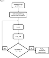
- FIG 3 a flowchart is shown which illustrates a method according to the invention.
- the delivery rate is reduced by reducing the speed of the drive for the pump 10 by ⁇ n. It is then checked whether the delivery flow V ( i ) experiences a reduction in the respective step. If this is not the case, a further iteration of the method can be started. If this is already the case, the optimization is ended and the speed in the previous step is used to determine the target delivery rate.
- the method according to the invention cannot only be carried out with speed-regulated pumps.
- the changes in the delivery rate of the pump system can also take place with variable displacement pumps (then controlled and / or regulated according to the pump speed and / or pump displacement angle) or by switching off pumps in the pump system.
Landscapes
- Engineering & Computer Science (AREA)
- Mechanical Engineering (AREA)
- Physics & Mathematics (AREA)
- Manufacturing & Machinery (AREA)
- General Engineering & Computer Science (AREA)
- Automation & Control Theory (AREA)
- General Physics & Mathematics (AREA)
- Health & Medical Sciences (AREA)
- Oral & Maxillofacial Surgery (AREA)
- Thermal Sciences (AREA)
- Fluid Mechanics (AREA)
- Computer Hardware Design (AREA)
- Control Of Positive-Displacement Pumps (AREA)
- Injection Moulding Of Plastics Or The Like (AREA)
- Control Of Non-Positive-Displacement Pumps (AREA)
Claims (16)
- Procédé pour trouver une capacité de transport de consigne d'un système de pompage (7) présentant au moins une pompe (10) pour le transport d'un fluide de thermorégulation à travers au moins un canal de thermorégulation (4, 5) d'un moule (6) au moyen de l'au moins une pompe (10), dans lequela) une régulation d'au moins un débit volumique de thermorégulation à travers l'au moins un canal de thermorégulation (4, 5) est réalisée selon une grandeur de régulation au moyen d'au moins un restricteur (12) en tant qu'organe de réglage, de sorte que l'au moins un débit volumique de thermorégulation reste sensiblement constant,b) un débit de transport du système de pompage (7) est mesuré,c) l'au moins une pompe (10) est commandée à partir d'une capacité de transport de départ indépendamment de la régulation de l'au moins un débit volumique de thermorégulation, de sorte qu'une capacité de transport du système de pompage (7) est réduite à une capacité de transport réduite, etd) il est contrôlé ensuite si le débit de transport reste sensiblement constant et,i. si tel est le cas, la capacité de transport réduite est déterminée comme capacité de transport de consigne ou,ii. si tel n'est pas le cas malgré la régulation de l'au moins un débit volumique de thermorégulation, la capacité de transport de départ est déterminée comme capacité de transport de consigne.
- Procédé pour trouver une capacité de transport de consigne d'un système de pompage (7) présentant au moins une pompe (10) pour le transport d'un fluide de thermorégulation à travers au moins un canal de thermorégulation (4, 5) d'un moule (6) au moyen de l'au moins une pompe (10), dans lequela) une régulation d'au moins un débit volumique de thermorégulation à travers l'au moins un canal de thermorégulation (4, 5) est réalisée selon une grandeur de régulation au moyen d'au moins un restricteur (12) en tant qu'organe de réglage, de sorte que l'au moins un débit volumique de thermorégulation reste sensiblement constant,b) un débit de transport du système de pompage (7) est mesuré,c) l'au moins une pompe (10) est commandée à partir d'une capacité de transport de départ indépendamment de la régulation de l'au moins un débit volumique de thermorégulation, de sorte qu'une capacité de transport du système de pompage est augmentée à (7) une capacité de transport augmentée, etd) il est ensuite contrôlé si le débit de transport reste sensiblement constant et,i. si tel n'est pas le cas malgré la régulation de l'au moins un débit volumique de thermorégulation, la capacité de transport augmentée est déterminée comme capacité de transport de consigne ou,ii. si tel est le cas, la capacité de transport de départ est déterminée comme capacité de transport de consigne.
- Procédé selon la revendication 1 ou 2, caractérisé en ce que la mesure du débit de transport du système de pompage (7) est réalisée au moyen d'un capteur monté en amont et/ou en aval du système de pompage (7).
- Procédé selon l'une quelconque des revendications précédentes, caractérisé en ce que la mesure du débit de transport du système de pompage (7) est réalisée dans le cadre de la régulation de l'au moins un débit volumique de thermorégulation.
- Procédé selon l'une quelconque des revendications précédentes, caractérisé en ce que les étapes de procédé c) et d) y compris i. et ii. sont réalisées plusieurs fois, dans lequel respectivement la capacité de transport de consigne provenant de la réalisation précédente est utilisée comme capacité de transport de départ.
- Procédé selon la revendication 5, caractérisé en ce que le procédé est terminé lorsque le cas ii. se produit.
- Procédé selon l'une quelconque des revendications précédentes, caractérisé en ce que le procédé est démarré lorsque- ceci est demandé par un utilisateur par entrée d'une capacité de transport de départ et/ou- lorsque la capacité de transport du système de pompage (7) ne subit sensiblement aucune modification pendant un laps de temps prédéfini.
- Procédé selon l'une quelconque des revendications précédentes, caractérisé en ce que plusieurs restricteurs (12) sont utilisés dans plusieurs canaux de thermorégulation (4, 5), dans lequel les restricteurs (12) sont régulés de préférence indépendamment les uns des autres.
- Système de pompage pour transporter un fluide de thermorégulation à travers au moins un canal de thermorégulation (4, 5) d'un moule, en particulier fonctionnant selon l'une quelconque des revendications 1 à 8, avec au moins une pompe (10) ainsi qu'un dispositif de commande (8) pour commander l'au moins une pompe (10), lequel présente une entrée de signal (9) pour des valeurs de mesure d'un capteur de débit volumique pour détecter une capacité de transport du système de pompage (7), caractérisé en ce que le dispositif de commande (8) est réalisé- pour commander l'au moins une pompe (10) à partir d'une capacité de transport de départ indépendamment d'une régulation séparée d'au moins un débit volumique de thermorégulation selon une grandeur de régulation, de sorte qu'une capacité de transport du système de pompage (7) est réduite à une capacité de transport réduite, et- pour contrôler ensuite si le débit de transport reste sensiblement constant et,i. si tel est le cas, pour déterminer la capacité de transport réduite comme une capacité de transport de consigne ou,ii. si tel n'est pas le cas, pour déterminer la capacité de transport de départ comme capacité de transport de consigne.
- Système de pompage pour transporter un fluide de thermorégulation à travers au moins un canal de thermorégulation (4, 5) d'un moule, en particulier fonctionnant selon l'une quelconque des revendications 1 à 8, avec au moins une pompe (10) ainsi qu'un dispositif de commande (8) pour commander l'au moins une pompe (10), lequel présente une entrée de signal (9) pour des valeurs de mesure d'un capteur de débit volumique pour détecter une capacité de transport du système de pompage (7), caractérisé en ce que le dispositif de commande (8) est réalisé- pour commander l'au moins une pompe (10) à partir d'une capacité de transport de départ indépendamment d'une régulation séparée d'au moins un débit volumique de thermorégulation selon une grandeur de régulation, de sorte qu'une capacité de transport du système de pompage (7) est augmentée à une capacité de transport augmentée, et- pour contrôler ensuite si le débit de transport reste sensiblement constant et,i. si tel n'est pas le cas, pour déterminer la capacité de transport augmentée comme une capacité de transport de consigne ou,ii. si tel est le cas, pour déterminer la capacité de transport de départ comme capacité de transport de consigne.
- Système de pompage selon la revendication 9 ou 10, caractérisé en ce qu'un répartiteur (1) est prévu pour la répartition du débit de transport sur plusieurs canaux de thermorégulation (4, 5) - de préférence montés en parallèle.
- Système de pompage selon la revendication 11, caractérisé en ce qu'un restricteur (12) comme organe de réglage pour la régulation de l'au moins un débit volumique de thermorégulation est prévu dans chacun des canaux de thermorégulation (4, 5).
- Machine de façonnage avec un système de pompage selon l'une quelconque des revendications 9 à 12.
- Machine de façonnage selon la revendication 13, caractérisée en ce que le dispositif de commande (8) est intégré dans une commande de machine centrale de la machine de façonnage ou est réalisé séparément de la commande de machine centrale.
- Machine de façonnage selon la revendication 13 ou 14, caractérisée en ce qu'un dispositif de régulation (2) pour la régulation de l'au moins un débit volumique de thermorégulation est intégré dans une commande de machine centrale de la machine de façonnage ou réalisé séparément de la commande de machine centrale.
- Appareil de thermorégulation avec un système de pompage selon l'une quelconque des revendications 9 à 12.
Applications Claiming Priority (1)
| Application Number | Priority Date | Filing Date | Title |
|---|---|---|---|
| ATA50925/2016A AT519157B1 (de) | 2016-10-14 | 2016-10-14 | Verfahren zum Auffinden einer Soll-Förderleistung eines Pumpensystems |
Publications (2)
| Publication Number | Publication Date |
|---|---|
| EP3309402A1 EP3309402A1 (fr) | 2018-04-18 |
| EP3309402B1 true EP3309402B1 (fr) | 2021-09-15 |
Family
ID=59966647
Family Applications (1)
| Application Number | Title | Priority Date | Filing Date |
|---|---|---|---|
| EP17192909.4A Active EP3309402B1 (fr) | 2016-10-14 | 2017-09-25 | Procédé de détermination d'un débit cible d'un système de pompage |
Country Status (5)
| Country | Link |
|---|---|
| US (1) | US11458655B2 (fr) |
| EP (1) | EP3309402B1 (fr) |
| KR (1) | KR101958569B1 (fr) |
| CN (1) | CN107956679B (fr) |
| AT (1) | AT519157B1 (fr) |
Families Citing this family (7)
| Publication number | Priority date | Publication date | Assignee | Title |
|---|---|---|---|---|
| KR101828345B1 (ko) * | 2016-10-19 | 2018-03-29 | 주식회사 로킷 | 바이오 3차원 프린터 |
| MY209119A (en) * | 2020-06-16 | 2025-06-23 | Daikin Res & Development Malaysia Sdn Bhd | System and method for controlling fluid flow |
| DE102021104375A1 (de) | 2021-02-24 | 2022-08-25 | Arburg Gmbh + Co Kg | Vorrichtung und Verfahren zur geregelten Durchflusstemperierung einer Spritzgießform |
| AT524681B1 (de) * | 2021-03-13 | 2022-08-15 | Wittmann Tech Gmbh | Verfahren für die Temperierung eines formgebenden Werkzeuges in Spritzgieß-, Druckguss- und Extrusionsanwendungen |
| AT526288B1 (de) | 2022-07-12 | 2024-06-15 | Engel Austria Gmbh | Verfahren, Computerprogrammprodukt und System zum Temperieren eines Formwerkzeugs |
| AT527755B1 (de) | 2024-07-09 | 2025-06-15 | Engel Austria Gmbh | Temperiersystem zum Temperieren von Komponenten von Produktionszellen |
| CN120100764B (zh) * | 2025-03-26 | 2026-01-09 | 利欧集团泵业科技有限公司 | 一种高速泵冷却联控系统及其应用的方法 |
Family Cites Families (12)
| Publication number | Priority date | Publication date | Assignee | Title |
|---|---|---|---|---|
| DE10064783A1 (de) * | 2000-12-22 | 2002-05-23 | Oni Waermetrafo Gmbh | Verfahren und Vorrichtung zum Kühlen von Werkzeugen |
| DE10119567C1 (de) * | 2001-04-21 | 2002-06-20 | Illig Maschinenbau Adolf | Verfahren zum Kühlen der beiden Werkzeughälften eines Formwerkzeuges und Mischeinheit zur Durchführung des Verfahrens |
| KR100470835B1 (ko) | 2002-01-28 | 2005-03-08 | 임채복 | 금형온도 제어 시스템 |
| DE102007013202A1 (de) * | 2007-03-15 | 2008-09-18 | Bühler Druckguss AG | Verfahren und Vorrichtung zum Temperieren von Giessformen |
| DE102008045006A1 (de) | 2008-08-29 | 2010-03-04 | Kraussmaffei Technologies Gmbh | Verfahren und Vorrichtung zur variothermen Temperierung von Spritzgießwerkzeugen |
| DK2667989T3 (da) | 2011-01-25 | 2020-08-24 | Lego As | Fremgangsmåde til fremstilling af en formdel med en kanal til temperaturregulering og en formdel fremstillet ved hjælp af fremgangsmåden |
| KR101330525B1 (ko) | 2013-01-04 | 2013-11-18 | 주식회사 어코드시스템 | 금형 온도조절장치 및 금형 온도조절방법 |
| AT513870B1 (de) * | 2013-02-04 | 2014-12-15 | Engel Austria Gmbh | Verfahren zur Temperierung eines Formwerkzeugs |
| CN105026760A (zh) * | 2013-02-27 | 2015-11-04 | 株式会社松井制作所 | 液体供给装置 |
| DE102013204680A1 (de) | 2013-03-18 | 2014-09-18 | Krones Ag | Vorrichtung zum steuern eines temperiergeräts einer blasformmaschine und verfahren zum steuern eines temperiergeräts einer blasform-maschine |
| AT515948B1 (de) * | 2014-07-03 | 2016-01-15 | Engel Austria Gmbh | Verfahren und Vorrichtung zur Temperierung eines Formwerkzeugs |
| KR101782781B1 (ko) | 2016-06-16 | 2017-09-29 | 대한전기공업 주식회사 | 금형용 온도조절장치 |
-
2016
- 2016-10-14 AT ATA50925/2016A patent/AT519157B1/de active
-
2017
- 2017-09-25 EP EP17192909.4A patent/EP3309402B1/fr active Active
- 2017-10-12 US US15/782,042 patent/US11458655B2/en active Active
- 2017-10-13 KR KR1020170133102A patent/KR101958569B1/ko not_active Expired - Fee Related
- 2017-10-13 CN CN201710949666.5A patent/CN107956679B/zh active Active
Also Published As
| Publication number | Publication date |
|---|---|
| KR20180041598A (ko) | 2018-04-24 |
| CN107956679A (zh) | 2018-04-24 |
| AT519157B1 (de) | 2018-06-15 |
| CN107956679B (zh) | 2020-04-28 |
| US11458655B2 (en) | 2022-10-04 |
| KR101958569B1 (ko) | 2019-03-14 |
| US20180104864A1 (en) | 2018-04-19 |
| AT519157A1 (de) | 2018-04-15 |
| EP3309402A1 (fr) | 2018-04-18 |
Similar Documents
| Publication | Publication Date | Title |
|---|---|---|
| EP3309402B1 (fr) | Procédé de détermination d'un débit cible d'un système de pompage | |
| AT403856B (de) | Verfahren zum temperieren einer spritzgiessform | |
| EP3661720B2 (fr) | Procédé de thermorégulation variothermique d'outils de moulage par injection | |
| EP2366830B1 (fr) | Système et procédé d'application d'un revêtement routier | |
| DE112008001368B4 (de) | Anzeigevorrichtung für eine Spritzgussvorrichtung | |
| DE102010052254B4 (de) | Automatische Schmiervorrichtung für eine Spritzgießmaschine | |
| EP2762291B1 (fr) | Dispositif et procédé de thermorégulation d'un outil de formage ou d'un composant d'une machine de formage | |
| EP2192309A2 (fr) | Procédé et commutation de réglage destinés au réglage d'une arrivée de moyen de pression pour un actionneur hydraulique | |
| EP2923837A1 (fr) | Procédé de réduction de la charge de pointe dans une presse | |
| AT515948B1 (de) | Verfahren und Vorrichtung zur Temperierung eines Formwerkzeugs | |
| EP2174769A1 (fr) | Procédé de moulage par injection et installation correspondante | |
| AT513872B1 (de) | Temperiervorrichtung für ein Formwerkzeug sowie Verfahren zum Betrieb derselben | |
| DE102015002711A1 (de) | Verfahren zum Betrieb eines Hydrauliksystems eines selbstfahrenden Straßenfertigers, Hydrauliksystem, insbesondere zur Durchführung des Verfahrens, sowie Straßenfertiger mit einem solchen Hydrauliksystem | |
| DE102008015067B3 (de) | Vorrichtung zur Herstellung von Beton-Fertigteilen | |
| EP3376141B1 (fr) | Agencement et procédé destinés à la préparation de poissons | |
| AT526288B1 (de) | Verfahren, Computerprogrammprodukt und System zum Temperieren eines Formwerkzeugs | |
| EP3267039B1 (fr) | Procédé et système de réglage d'une installation de pompage | |
| AT519283B1 (de) | Verfahren zur herstellung von kunststoffprofilen | |
| DE102011084194A1 (de) | Verfahren und Recheneinheit zum Betrieb einer Zumesseinheit eines Common-Rail-Kraftstoffeinspritzsystems und Recheneinheit | |
| DE102013006398A1 (de) | Automatische Schmierfettzufuhrvorrichtung einer Spritzgussmachine | |
| EP3765216B1 (fr) | Groupe de refroidissement pour un dispositif de refroidissement laminaire | |
| EP4116493A1 (fr) | Finisseuse de route pourvue d'un dispositif de chauffage, ainsi que procédé | |
| EP4049825B1 (fr) | Dispositif et procédé de régulation de la température de l'écoulement d'un moule de moulage par injection | |
| DE102015213169A1 (de) | Verfahren zum Erkennen einer Änderung eines Kühlverhaltens einer elektrischen Maschine | |
| EP2815844A1 (fr) | Réglage de l'épaisseur pour meuleuses |
Legal Events
| Date | Code | Title | Description |
|---|---|---|---|
| PUAI | Public reference made under article 153(3) epc to a published international application that has entered the european phase |
Free format text: ORIGINAL CODE: 0009012 |
|
| STAA | Information on the status of an ep patent application or granted ep patent |
Free format text: STATUS: THE APPLICATION HAS BEEN PUBLISHED |
|
| AK | Designated contracting states |
Kind code of ref document: A1 Designated state(s): AL AT BE BG CH CY CZ DE DK EE ES FI FR GB GR HR HU IE IS IT LI LT LU LV MC MK MT NL NO PL PT RO RS SE SI SK SM TR |
|
| AX | Request for extension of the european patent |
Extension state: BA ME |
|
| STAA | Information on the status of an ep patent application or granted ep patent |
Free format text: STATUS: REQUEST FOR EXAMINATION WAS MADE |
|
| 17P | Request for examination filed |
Effective date: 20181001 |
|
| RBV | Designated contracting states (corrected) |
Designated state(s): AL AT BE BG CH CY CZ DE DK EE ES FI FR GB GR HR HU IE IS IT LI LT LU LV MC MK MT NL NO PL PT RO RS SE SI SK SM TR |
|
| GRAP | Despatch of communication of intention to grant a patent |
Free format text: ORIGINAL CODE: EPIDOSNIGR1 |
|
| STAA | Information on the status of an ep patent application or granted ep patent |
Free format text: STATUS: GRANT OF PATENT IS INTENDED |
|
| INTG | Intention to grant announced |
Effective date: 20210707 |
|
| GRAS | Grant fee paid |
Free format text: ORIGINAL CODE: EPIDOSNIGR3 |
|
| GRAA | (expected) grant |
Free format text: ORIGINAL CODE: 0009210 |
|
| STAA | Information on the status of an ep patent application or granted ep patent |
Free format text: STATUS: THE PATENT HAS BEEN GRANTED |
|
| AK | Designated contracting states |
Kind code of ref document: B1 Designated state(s): AL AT BE BG CH CY CZ DE DK EE ES FI FR GB GR HR HU IE IS IT LI LT LU LV MC MK MT NL NO PL PT RO RS SE SI SK SM TR |
|
| REG | Reference to a national code |
Ref country code: CH Ref legal event code: EP |
|
| RIN1 | Information on inventor provided before grant (corrected) |
Inventor name: BALKA, CHRISTOPH |
|
| REG | Reference to a national code |
Ref country code: DE Ref legal event code: R096 Ref document number: 502017011491 Country of ref document: DE |
|
| REG | Reference to a national code |
Ref country code: IE Ref legal event code: FG4D Free format text: LANGUAGE OF EP DOCUMENT: GERMAN |
|
| REG | Reference to a national code |
Ref country code: AT Ref legal event code: REF Ref document number: 1430716 Country of ref document: AT Kind code of ref document: T Effective date: 20211015 |
|
| REG | Reference to a national code |
Ref country code: LT Ref legal event code: MG9D |
|
| REG | Reference to a national code |
Ref country code: NL Ref legal event code: MP Effective date: 20210915 |
|
| PG25 | Lapsed in a contracting state [announced via postgrant information from national office to epo] |
Ref country code: RS Free format text: LAPSE BECAUSE OF FAILURE TO SUBMIT A TRANSLATION OF THE DESCRIPTION OR TO PAY THE FEE WITHIN THE PRESCRIBED TIME-LIMIT Effective date: 20210915 Ref country code: SE Free format text: LAPSE BECAUSE OF FAILURE TO SUBMIT A TRANSLATION OF THE DESCRIPTION OR TO PAY THE FEE WITHIN THE PRESCRIBED TIME-LIMIT Effective date: 20210915 Ref country code: HR Free format text: LAPSE BECAUSE OF FAILURE TO SUBMIT A TRANSLATION OF THE DESCRIPTION OR TO PAY THE FEE WITHIN THE PRESCRIBED TIME-LIMIT Effective date: 20210915 Ref country code: BG Free format text: LAPSE BECAUSE OF FAILURE TO SUBMIT A TRANSLATION OF THE DESCRIPTION OR TO PAY THE FEE WITHIN THE PRESCRIBED TIME-LIMIT Effective date: 20211215 Ref country code: LT Free format text: LAPSE BECAUSE OF FAILURE TO SUBMIT A TRANSLATION OF THE DESCRIPTION OR TO PAY THE FEE WITHIN THE PRESCRIBED TIME-LIMIT Effective date: 20210915 Ref country code: NO Free format text: LAPSE BECAUSE OF FAILURE TO SUBMIT A TRANSLATION OF THE DESCRIPTION OR TO PAY THE FEE WITHIN THE PRESCRIBED TIME-LIMIT Effective date: 20211215 Ref country code: FI Free format text: LAPSE BECAUSE OF FAILURE TO SUBMIT A TRANSLATION OF THE DESCRIPTION OR TO PAY THE FEE WITHIN THE PRESCRIBED TIME-LIMIT Effective date: 20210915 |
|
| PG25 | Lapsed in a contracting state [announced via postgrant information from national office to epo] |
Ref country code: LV Free format text: LAPSE BECAUSE OF FAILURE TO SUBMIT A TRANSLATION OF THE DESCRIPTION OR TO PAY THE FEE WITHIN THE PRESCRIBED TIME-LIMIT Effective date: 20210915 Ref country code: GR Free format text: LAPSE BECAUSE OF FAILURE TO SUBMIT A TRANSLATION OF THE DESCRIPTION OR TO PAY THE FEE WITHIN THE PRESCRIBED TIME-LIMIT Effective date: 20211216 |
|
| REG | Reference to a national code |
Ref country code: BE Ref legal event code: MM Effective date: 20210930 |
|
| PG25 | Lapsed in a contracting state [announced via postgrant information from national office to epo] |
Ref country code: IS Free format text: LAPSE BECAUSE OF FAILURE TO SUBMIT A TRANSLATION OF THE DESCRIPTION OR TO PAY THE FEE WITHIN THE PRESCRIBED TIME-LIMIT Effective date: 20220115 Ref country code: SM Free format text: LAPSE BECAUSE OF FAILURE TO SUBMIT A TRANSLATION OF THE DESCRIPTION OR TO PAY THE FEE WITHIN THE PRESCRIBED TIME-LIMIT Effective date: 20210915 Ref country code: SK Free format text: LAPSE BECAUSE OF FAILURE TO SUBMIT A TRANSLATION OF THE DESCRIPTION OR TO PAY THE FEE WITHIN THE PRESCRIBED TIME-LIMIT Effective date: 20210915 Ref country code: RO Free format text: LAPSE BECAUSE OF FAILURE TO SUBMIT A TRANSLATION OF THE DESCRIPTION OR TO PAY THE FEE WITHIN THE PRESCRIBED TIME-LIMIT Effective date: 20210915 Ref country code: PT Free format text: LAPSE BECAUSE OF FAILURE TO SUBMIT A TRANSLATION OF THE DESCRIPTION OR TO PAY THE FEE WITHIN THE PRESCRIBED TIME-LIMIT Effective date: 20220117 Ref country code: PL Free format text: LAPSE BECAUSE OF FAILURE TO SUBMIT A TRANSLATION OF THE DESCRIPTION OR TO PAY THE FEE WITHIN THE PRESCRIBED TIME-LIMIT Effective date: 20210915 Ref country code: NL Free format text: LAPSE BECAUSE OF FAILURE TO SUBMIT A TRANSLATION OF THE DESCRIPTION OR TO PAY THE FEE WITHIN THE PRESCRIBED TIME-LIMIT Effective date: 20210915 Ref country code: ES Free format text: LAPSE BECAUSE OF FAILURE TO SUBMIT A TRANSLATION OF THE DESCRIPTION OR TO PAY THE FEE WITHIN THE PRESCRIBED TIME-LIMIT Effective date: 20210915 Ref country code: EE Free format text: LAPSE BECAUSE OF FAILURE TO SUBMIT A TRANSLATION OF THE DESCRIPTION OR TO PAY THE FEE WITHIN THE PRESCRIBED TIME-LIMIT Effective date: 20210915 Ref country code: CZ Free format text: LAPSE BECAUSE OF FAILURE TO SUBMIT A TRANSLATION OF THE DESCRIPTION OR TO PAY THE FEE WITHIN THE PRESCRIBED TIME-LIMIT Effective date: 20210915 Ref country code: AL Free format text: LAPSE BECAUSE OF FAILURE TO SUBMIT A TRANSLATION OF THE DESCRIPTION OR TO PAY THE FEE WITHIN THE PRESCRIBED TIME-LIMIT Effective date: 20210915 |
|
| REG | Reference to a national code |
Ref country code: DE Ref legal event code: R097 Ref document number: 502017011491 Country of ref document: DE |
|
| PG25 | Lapsed in a contracting state [announced via postgrant information from national office to epo] |
Ref country code: MC Free format text: LAPSE BECAUSE OF FAILURE TO SUBMIT A TRANSLATION OF THE DESCRIPTION OR TO PAY THE FEE WITHIN THE PRESCRIBED TIME-LIMIT Effective date: 20210915 |
|
| PLBE | No opposition filed within time limit |
Free format text: ORIGINAL CODE: 0009261 |
|
| STAA | Information on the status of an ep patent application or granted ep patent |
Free format text: STATUS: NO OPPOSITION FILED WITHIN TIME LIMIT |
|
| PG25 | Lapsed in a contracting state [announced via postgrant information from national office to epo] |
Ref country code: LU Free format text: LAPSE BECAUSE OF NON-PAYMENT OF DUE FEES Effective date: 20210925 Ref country code: IE Free format text: LAPSE BECAUSE OF NON-PAYMENT OF DUE FEES Effective date: 20210925 Ref country code: DK Free format text: LAPSE BECAUSE OF FAILURE TO SUBMIT A TRANSLATION OF THE DESCRIPTION OR TO PAY THE FEE WITHIN THE PRESCRIBED TIME-LIMIT Effective date: 20210915 Ref country code: BE Free format text: LAPSE BECAUSE OF NON-PAYMENT OF DUE FEES Effective date: 20210930 |
|
| 26N | No opposition filed |
Effective date: 20220616 |
|
| GBPC | Gb: european patent ceased through non-payment of renewal fee |
Effective date: 20211215 |
|
| PG25 | Lapsed in a contracting state [announced via postgrant information from national office to epo] |
Ref country code: SI Free format text: LAPSE BECAUSE OF FAILURE TO SUBMIT A TRANSLATION OF THE DESCRIPTION OR TO PAY THE FEE WITHIN THE PRESCRIBED TIME-LIMIT Effective date: 20210915 |
|
| PG25 | Lapsed in a contracting state [announced via postgrant information from national office to epo] |
Ref country code: GB Free format text: LAPSE BECAUSE OF NON-PAYMENT OF DUE FEES Effective date: 20211215 |
|
| PG25 | Lapsed in a contracting state [announced via postgrant information from national office to epo] |
Ref country code: FR Free format text: LAPSE BECAUSE OF NON-PAYMENT OF DUE FEES Effective date: 20211115 |
|
| PG25 | Lapsed in a contracting state [announced via postgrant information from national office to epo] |
Ref country code: HU Free format text: LAPSE BECAUSE OF FAILURE TO SUBMIT A TRANSLATION OF THE DESCRIPTION OR TO PAY THE FEE WITHIN THE PRESCRIBED TIME-LIMIT; INVALID AB INITIO Effective date: 20170925 |
|
| PG25 | Lapsed in a contracting state [announced via postgrant information from national office to epo] |
Ref country code: CY Free format text: LAPSE BECAUSE OF FAILURE TO SUBMIT A TRANSLATION OF THE DESCRIPTION OR TO PAY THE FEE WITHIN THE PRESCRIBED TIME-LIMIT Effective date: 20210915 |
|
| REG | Reference to a national code |
Ref country code: AT Ref legal event code: MM01 Ref document number: 1430716 Country of ref document: AT Kind code of ref document: T Effective date: 20220925 |
|
| PG25 | Lapsed in a contracting state [announced via postgrant information from national office to epo] |
Ref country code: AT Free format text: LAPSE BECAUSE OF NON-PAYMENT OF DUE FEES Effective date: 20220925 |
|
| PG25 | Lapsed in a contracting state [announced via postgrant information from national office to epo] |
Ref country code: MK Free format text: LAPSE BECAUSE OF FAILURE TO SUBMIT A TRANSLATION OF THE DESCRIPTION OR TO PAY THE FEE WITHIN THE PRESCRIBED TIME-LIMIT Effective date: 20210915 |
|
| PG25 | Lapsed in a contracting state [announced via postgrant information from national office to epo] |
Ref country code: MT Free format text: LAPSE BECAUSE OF FAILURE TO SUBMIT A TRANSLATION OF THE DESCRIPTION OR TO PAY THE FEE WITHIN THE PRESCRIBED TIME-LIMIT Effective date: 20210915 |
|
| PGFP | Annual fee paid to national office [announced via postgrant information from national office to epo] |
Ref country code: IT Payment date: 20240924 Year of fee payment: 8 |
|
| REG | Reference to a national code |
Ref country code: CH Ref legal event code: U11 Free format text: ST27 STATUS EVENT CODE: U-0-0-U10-U11 (AS PROVIDED BY THE NATIONAL OFFICE) Effective date: 20251001 |
|
| PGFP | Annual fee paid to national office [announced via postgrant information from national office to epo] |
Ref country code: DE Payment date: 20250926 Year of fee payment: 9 |
|
| PG25 | Lapsed in a contracting state [announced via postgrant information from national office to epo] |
Ref country code: TR Free format text: LAPSE BECAUSE OF FAILURE TO SUBMIT A TRANSLATION OF THE DESCRIPTION OR TO PAY THE FEE WITHIN THE PRESCRIBED TIME-LIMIT Effective date: 20210915 |
|
| PGFP | Annual fee paid to national office [announced via postgrant information from national office to epo] |
Ref country code: CH Payment date: 20251001 Year of fee payment: 9 |