EP3311077B1 - Dispositif et méthode pour la climatisation d'un espace - Google Patents
Dispositif et méthode pour la climatisation d'un espace Download PDFInfo
- Publication number
- EP3311077B1 EP3311077B1 EP16730411.2A EP16730411A EP3311077B1 EP 3311077 B1 EP3311077 B1 EP 3311077B1 EP 16730411 A EP16730411 A EP 16730411A EP 3311077 B1 EP3311077 B1 EP 3311077B1
- Authority
- EP
- European Patent Office
- Prior art keywords
- surface element
- heat
- heat sink
- room
- interface
- Prior art date
- Legal status (The legal status is an assumption and is not a legal conclusion. Google has not performed a legal analysis and makes no representation as to the accuracy of the status listed.)
- Active
Links
Images


Classifications
-
- F—MECHANICAL ENGINEERING; LIGHTING; HEATING; WEAPONS; BLASTING
- F24—HEATING; RANGES; VENTILATING
- F24F—AIR-CONDITIONING; AIR-HUMIDIFICATION; VENTILATION; USE OF AIR CURRENTS FOR SCREENING
- F24F5/00—Air-conditioning systems or apparatus not covered by F24F1/00 or F24F3/00, e.g. using solar heat or combined with household units such as an oven or water heater
- F24F5/0089—Systems using radiation from walls or panels
-
- F—MECHANICAL ENGINEERING; LIGHTING; HEATING; WEAPONS; BLASTING
- F24—HEATING; RANGES; VENTILATING
- F24F—AIR-CONDITIONING; AIR-HUMIDIFICATION; VENTILATION; USE OF AIR CURRENTS FOR SCREENING
- F24F13/00—Details common to, or for air-conditioning, air-humidification, ventilation or use of air currents for screening
- F24F13/22—Means for preventing condensation or evacuating condensate
- F24F2013/221—Means for preventing condensation or evacuating condensate to avoid the formation of condensate, e.g. dew
Definitions
- the invention relates to a device and a method for air conditioning a room, in which thermal energy is absorbed from the room by means of at least one heat sink, which has at least one interface facing the room. For this purpose, the interface is brought to a lower temperature than a heat load.
- Devices and methods of the type mentioned at the beginning are also known under the terms thermal component activation or cooling ceiling.
- this known device has the disadvantage that the interface, which has direct contact with the room air, cannot be cooled below the limit temperature at which condensation sets in. The higher the relative humidity, the higher this limit temperature is. This means that, especially in humid tropical climates, only a relatively small temperature spread can be achieved without moisture precipitating on the thermally activated component and thus adversely affecting the room climate or causing structural damage. The effect of the known ones The device is therefore inadequate under hot, humid climate conditions.
- the invention is therefore based on the object of specifying a method and a device for room air conditioning which, on the one hand, is energy efficient and, on the other hand, has a good cooling effect even in humid climatic conditions.
- the object is achieved according to the invention by a device according to claim 1 and a method according to claim 11.
- a device for air conditioning a room which has at least one heat sink.
- the heat sink has at least one interface facing the room.
- the interface faces the room if thermal radiation from at least one heat load in the room can reach the interface directly or via at least one reflection surface.
- the heat sink can be part of a building, in particular a solid ceiling or wall.
- the heat sink can be designed as a plate heat exchanger, capillary tube mat, cooling plate or radiator and can be introduced into the room as a separate component.
- the heat sink can be designed as a ceiling panel or as a wall panel.
- the heat sink can be designed as a design room element or part of the furniture and can be integrated, for example, into a lighting device or a piece of furniture.
- the heat sink may be part of, or separate from, a vehicle, aircraft, or ship Component must be installed in the passenger compartment to improve the thermal comfort of the passengers.
- the heat sink has at least one interface facing the room.
- the interface can have a smooth or a rough surface in order to influence its absorption or reflection behavior.
- the interface can have a mineral surface, for example an interior plaster or a dispersion paint.
- the interface may include or consist of a metal or alloy.
- the performance of the device according to the invention can be increased due to the comparatively high thermal conductivity and/or high heat capacity. A low heat capacity of the heat sink can improve the response of the device.
- the interface may have an absorbent coating that exhibits greater than 90% or greater than 95% absorption at least in a portion of the infrared spectral range.
- an electroplated layer of black chrome or black nickel may be used.
- a layer or a layer system consisting of several individual layers can be applied in a sputtering process, for example a titanium oxynitride coating or other ceramic coatings.
- the interface facing the room is brought to a temperature that is lower than the heat load.
- a refrigerant can be cooled, for example, using a compression refrigeration machine or a heat pump, so that heat is removed from the heat sink.
- ground or surface water may be used to remove heat from the heat sink and the temperature of the interface to lower.
- thermoelectric coolers can be used, for example Peltier elements.
- the heat load can be selected from solar radiation, electrical or electronic devices or people in the room.
- the infrared heat radiation emitted by the heat load is absorbed by the interface of the heat sink and removed from the room by the refrigerant or the heat transfer fluid.
- the invention it is now proposed to arrange at least one surface element between the interface and the space, which is at least partially transparent to thermal radiation.
- the surface element is arranged at a distance from the interface, so that a gap is formed between the surface element and the interface, the surface element and the heat sink being enclosed with an edge composite, which closes the gap almost gas-tight from the environment and the device also has at least one dehumidification device contains, with which water can be removed from the space between the surface element and the interface.
- the surface element means that the ambient air in the room can no longer have a direct effect on the interface. Therefore, the moisture present in the room is kept away from the interface so that it does not condense on the interface.
- the interface can therefore be brought to a temperature below the dew point during operation of the device. This increases the efficiency of the device and yet prevents moisture from precipitating at the interface and contaminating the room, damaging devices or furnishings, inconveniencing people, causing structural damage and/or negatively affecting the room climate.
- the surface element is at least partially transparent to thermal radiation, all heat loads in the room that are at a higher temperature than the interface can emit infrared heat radiation, which is subsequently transmitted through the surface element and absorbed in the interface.
- Thermal radiation is electromagnetic radiation in the infrared wavelength range, so that it... spreads out in a straight line and penetrates the surface element.
- Term room temperature radiation can be used. The heat radiation is therefore efficiently absorbed by the heat sink, although the direct effect of the warm room air on the interface is prevented or reduced by the surface element.
- the surface element can have a transmission of about 50% to about 90% or from about 70% to about 80 at a wavelength between about 3 ⁇ m and about 30 ⁇ m or between about 6 ⁇ m and about 20 ⁇ m, at least in a partial area % exhibit. In some embodiments of the invention, the surface element can show a transmission of more than about 50% or more than about 70% or more than about 80% at least in a partial area at a wavelength between about 6 ⁇ m and about 20 ⁇ m.
- the wavelength range mentioned contains a large part of the energy of the thermal radiation of a black body at approximately 300 K. If the cooling device according to the invention is to be used in a warmer climate, this wavelength range can be shifted.
- Shorter wavelengths can also occur if the room has special heat sources, such as electrical or electronic devices.
- a transmission of approximately 50% to approximately 90% in at least a portion of the wavelength range mentioned ensures that a sufficient proportion of the thermal radiation reaches the interface of the heat sink and can in this way be transported out of the room.
- the transparency and the associated low degree of absorption and emissivity of the fabric in the above-mentioned wavelength range of the material ensure that the fabric releases little heat energy to the heat sink and therefore does not cool down and therefore does not fall below the dew point of the room air.
- the flat structure can be designed to be at least partially reflective and/or absorbent in the visible spectral range, so that a visually appealing design is made possible. For example, can The white ceiling color that is common in buildings will continue to be retained.
- the heat sink may include a tube register and/or a plate heat exchanger and/or a capillary tube mat.
- a refrigerant can flow through these.
- the refrigerant can be cooled using a compression refrigeration machine.
- the refrigerant may undergo a phase transition.
- the refrigerant can be groundwater and/or surface water, which is pumped through the pipe register or the plate heat exchanger. In this way, heat can be removed from the heat sink so that the interface facing the room cools to a lower temperature than the room.
- the surface element can be arranged at a distance from the interface, so that an intermediate space is formed between the surface element and the interface, which is filled with air or optionally with a protective gas.
- the protective gas can be selected from argon, nitrogen, synthetic air or dehumidified ambient air.
- the space between the surface element and the interface can be evacuated. In some embodiments, it is important that the gap has only a low water vapor partial pressure, so that the condensation of moisture at the interface is avoided. As a result, the interface remains dry so that the efficiency of the device does not decrease.
- the surface element facing the room is warmer than the interface when the device is in operation, since the gap can serve as insulation, so that the side of the surface element facing the room does not cool down below the dew point of the room air. This can prevent the occurrence of structural damage, such as mold.
- the dehumidification device By means of the dehumidification device according to the invention, water which penetrates through the at least one surface element or the edge composite during operation of the device can be removed from the intermediate space. This means that the gap can be reliably kept free of water, so that the interface is free of condensate or at least the accumulation of condensate can be reduced and transported away from the interface. This enables trouble-free operation over a longer period of time.
- the dehumidification device can contain or consist of at least one sorbent and/or at least one micropump and/or at least one heating device and/or at least one valve and/or at least one fan and/or a fleece. Moisture occurring in the gap can therefore either be chemically sorbed, for example using silica gel, zeolites or similar drying agents.
- a micropump can cumulatively or alternatively be present, which pumps out any moisture and condensate that occurs from the intermediate space.
- the moisture can be driven out of a sorbent and/or the intermediate space can be heated dry by means of at least one heating device.
- valves can be present which either work as spring-loaded check valves and/or can be controlled by means of mechanical drive means, for example by electromagnetic coils or piezo actuators.
- mechanical drive means for example by electromagnetic coils or piezo actuators.
- the intermediate space can be flushed with dry protective gas, which is passed through the fan or another conveying device is supplied to the intermediate space and leaves it through at least one valve.
- the at least one surface element may contain a polymer.
- the polymer may be selected from polyethylene and/or polymethyl methacrylate and/or polyvinyl chloride and/or polypropylene and/or polyethylene terephthalate and/or polyester and/or biaxially oriented polyester film and/or cellulose acetate butyrate and/or cellulose acetate polymer. These materials have a high diffusion resistance to water vapor, meaning that only a small amount of moisture can penetrate into the gap. In addition, due to their resistance to breakage, these surface elements can also be used safely as overhead glazing if the heat sink is arranged with the interface in the ceiling area.
- the device may contain one, two or three surface elements, each of which is arranged at a distance from one another and from the interface. As a result, several gaps are formed, so that the air humidity is kept away from the interface with greater reliability and/or a larger temperature difference can exist between the heat load and the interface due to the improved thermal insulation.
- the at least one surface element and the heat sink can be enclosed with an edge composite which contains at least one sealing element.
- the sealing element may contain or consist of polyisobutylene and/or silicone and/or butyl rubber.
- Such an edge connection can be designed in a similar way to known insulating glass pane edge joints. This makes the penetration of moisture into the gap through the sealing elements of the edge seal reliable and permanent prevented, so that the device has a long service life even with daily use.
- the at least one surface element and the heat sink can be enclosed with an edge composite, which is carried out by thermal joining. This allows rapid and cost-effective production and/or the edge connection can be made particularly dense.
- the at least one surface element can be connected to a frame which is fastened to the heat sink and the other components of the device by mechanical or magnetic closure means. This allows the surface element to be easily replaced in the event of damage or for inspection.
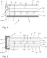
- Figure 1 shows a first embodiment of the device 1 for air conditioning a room 2. Shown is a cross section through a device according to the invention.
- the device 1 contains a heat sink 10 with at least one interface 100.
- the heat sink 10 may contain a material with high thermal conductivity, for example a metal or an alloy, in particular an aluminum or copper alloy.
- the interface 100 may be provided with an infrared-absorbing coating, for example a paint, a sputtering layer or a galvanic layer. In particular, the absorption of room temperature radiation can be increased as a result.
- the surface of the heat sink 10 opposite the interface 100 is provided with thermal insulation 120.
- the thermal insulation 120 can contain or consist of rigid foam or vacuum insulation or mineral wool.
- the thermal insulation 120 can have a multi-layer structure.
- the side of the thermal insulation 120 facing away from the heat sink 10 is covered with a stiffening element 12, which on the one hand is mechanical Can stabilize the device and can also provide a decorative look when placed freely in the room.
- the stiffening element 12 can be, for example, a plastic plate, a sheet of metal, a hardboard, a medium-density fiberboard or another wood material.
- the device can be attached to a ceiling with the back of the stiffening element 12, for example by gluing or screwing, as shown in Figure 18 will still be explained.
- a tube register 11 is present in the exemplary embodiment shown, through which water or another known refrigerant can flow, for example.
- the pipe register removes heat from the heat sink during operation, as shown by Figure 8 will be explained in more detail.
- the refrigerant is supplied to the tube register 11 via a line 110.
- the interface 100 faces the space 2, so that heat radiation from the space 2 can reach the interface 100 and is absorbed there.
- two surface elements 31 and 32 are present in the exemplary embodiment shown. These each include an intermediate space 310 and 320, which is either evacuated or contains a protective gas atmosphere.
- the protective gas atmosphere is characterized by a small proportion of gaseous water or moisture, so that the moisture does not precipitate at the interface 100. Nevertheless, the surface elements 31 and 32 are at least partially in the infrared spectral range Room temperature radiation is transparent or translucent, so that the heat radiation from room 2 penetrates through the surface elements 31 and 32 and can be absorbed by the interface 100. This allows the device, which can be designed, for example, as a cooling ceiling or wall element, to be operated even at high humidity and large temperature spreads, without moisture loss and subsequent structural damage occurring.
- the surface elements 31 and 32 can consist of glass or sintered, IR-transparent materials or plastic. Particularly when used overhead on ceiling elements, a plastic element can be used advantageously due to its low weight and breaking strength. Such a plastic element can consist of or contain a film web.
- Figure 1 further shows an edge composite 13, which accommodates the ends of the surface elements 31 and 32 and closes them in an approximately gas-tight manner, so that no moisture from the environment can penetrate into the first gap 310 and the second gap 320 at the edge.
- Figure 1 also shows an optional dehumidification device 4, which is integrated into the edge composite 13 and with which penetrating water can be removed from the gap 310 and 320.
- a first valve 41 is assigned to the first gap 310.
- a second valve 42 is assigned to the second gap 320.
- the valves can be designed as check valves so that they release an air flow 39 to the outside when a dry gas flow is supplied to the spaces 310 and 320 by means of a fan or other conveying device, which expels the moisture from the spaces.
- the valves 41 and 42 can be used to equalize pressure be used when the pressure of the gas atmosphere in the first gap 310 and in the second gap 320 drops due to cooling, so that the surface elements 31 and 32 always remain flat during operation.
- the surface elements 31 and 32 can be stabilized during operation of the device by an overpressure in the gaps 310 and 320.
- FIG. 2 shows a heat sink 10, which can consist, for example, of a capillary tube mat made of a metal or an alloy.
- a tube register 11 is installed in the heat sink 10, through which a heat transfer medium can flow in order to dissipate heat from the heat sink 10.
- the heat sink 10 has two interfaces 100a and 100b, which are arranged on opposite surfaces of the heat sink 10. Thus, the area available for cooling can be doubled in order to increase the performance of the device.
- a first gap 310 is arranged between the surface elements 31 and 32.
- a second gap 320 is arranged between the second surface element and the third surface element 33.
- a third gap 330 is formed between the third surface element 33 and the first interface 100a.
- a sixth surface element 36 is provided as a conclusion, which, together with the fifth surface element 35, delimits a sixth intermediate space 360.
- the insulation can be further improved by three surface elements and three gaps, so that, on the one hand, undesirable cooling of the outermost surface element facing the room is avoided and, on the other hand, the penetration of moisture is further reduced, since each gap has only a small moisture gradient in relation to its neighboring gap.
- the second embodiment can be suspended from a ceiling so that heat radiation hits the heat sink 10 from both sides.
- the edge composite 13 there is an edge composite 13 on the device 1, which encloses the heat sink 10 and the six surface elements.
- the edge composite 13 has a cavity 130, which can be provided with an optional sorbent 45 or a seal.
- the sorbent 45 removes moisture that has penetrated from the spaces 310, 320, 330, 340, 350 and 360.
- At least one optional heating element 44 can be provided.
- the heating element 44 can either be designed as a pipe register through which a heat transfer medium can flow.
- a heat transfer medium For example, oil or heating water can be used for this.
- the heating device 44 can contain or consist of an electrical heating element in order to be able to regenerate the sorbent 45 independently of a central heating system.
- FIG. 3 shows a third embodiment of the present invention. Since this third embodiment is similar to the second embodiment described above, the following description is limited to the essential differences. In this case too, the same reference numbers designate the same components.
- the main difference in the third embodiment relates to the edge composite 13.
- This contains a sealing element 131, which contains or consists of, for example, polyisobutylene and/or silicone and/or butyl rubber.
- the edge connection therefore has a similar structure to a known insulating glass pane edge joint.
- the edge connection can therefore be produced using methods known per se from the production of insulating glass windows, so that the surface elements and the heat sink 10 are reliably sealed with little effort.
- the micropump 46 in the edge composite 13. This is provided with connecting lines 460, which each open into the spaces 310 and 320. In this way, the micropump 46 can remove moisture from the gaps 310 and 320 and dissipate it as a moisture stream 465. This allows the first gap 310 and the second gap 320 to dry out continuously, so that the device can be operated reliably even over a longer period of operation.
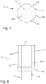
- the fifth embodiment which in Figure 7 shown in section, includes a plurality of cylindrical heat sinks which have an approximately tubular appearance. These are arranged at the focal point of a reflector 6.
- the reflector 6 is circular in cross section. Of course, other shapes of the reflector 6 can also be used, for example hyperbolic or parabolic cross sections.
- the heat sinks are arranged in the focal point or the focal area of the reflectors 6. In this way, heat radiation 20, which hits the reflectors 6 from the room, is focused on the heat sink.
- the reflectors 6 can be made of a metal or an alloy, for example.
- the reflectors 6 can also have an infrared-reflecting coating to increase the efficiency of the device. The coating can be applied galvanically and/or from the gas phase, for example using known CVD or PVD or sputtering processes.
- the heat sinks located at the focal point are in Figure 5 in cross section and in Figure 6 shown in longitudinal section.
- the heat sink 10 is approximately circular cylindrical and forms the core of a concentric arrangement of several surface elements 31 and 32.
- the heat sink 10 can be actively cooled, for example by a tube bundle heat exchanger, a tube register or others , measures known per se.
- the cylindrical surface of the tubular heat sink 10 serves as an interface 100.
- first surface element 31 In order to avoid condensation of room moisture on the interface 100, it is surrounded concentrically by a first surface element 31 and a second surface element 32.
- the surface elements therefore have the shape of a tube or a hollow cylinder.
- Intermediate spaces 310 and 320 are formed between the surface elements and the interface 10, which, on the one hand, isolate the interface 100 from the room and, on the other hand, prevent direct access to air.
- the spaces 310 and 320 can either be evacuated as described above or provided with a protective gas atmosphere.
- tubular elements can in turn be provided at their end with an edge seal and/or a sorbent 45, so that moisture 39 can be removed from the spaces 310 and 320.
- Figure 8 shows a device 1 for room air conditioning. This contains an interface 100 and at least one surface element 31 as described above. Thermal radiation 20 from room 2 is emitted isotropically and thus also partially reaches the interface 100.
- the interface 100 also emits thermal radiation 21, which is radiated into the room 2. However, since the temperature of the interface 100 is lower than the temperature of the heat loads in the room, the heat flow 21 is less than the heat flow 20, so that a net heat flow is removed from the room 2. This is deposited in the heat sink 10 of the device 1.
- the heat sink 10 is supplied with a cooling medium, for example groundwater.
- the cooling medium has a finite temperature and thus carries a heat flow 23 into the heat sink 10.
- the cooling medium leads a heat flow 25 from the heat sink 10, which is larger than the supplied heat 23. This means that the heat sink 10 can be reliably cooled and the net heat flow can be permanently removed from the room 2.
- the cooling power may be greater than about 70 W m -2 or greater than about 90 W m -2 or greater than about 100 W m -2 .
- FIG. 9 A sixth embodiment of the air conditioning device according to the invention is explained in more detail.
- the device 1 for air conditioning is constructed similarly to that described above Figures 1 and 4 described.
- This embodiment of the invention also contains thermal insulation 120, on which the heat sink 10 is applied. The direct access of the room air with the moisture contained therein to the heat sink 10 is prevented by the surface element 31, which is arranged at a distance 310 from the interface 100 of the heat sink 10.
- the device 1 according to the sixth embodiment does not have a capillary tube mat as a heat sink 10.
- the heat sink 10 essentially consists of a flat layer of material made of a metal or an alloy, for example aluminum or copper. This is connected on at least one edge to a tube 11 in which a cold medium can flow.
- the cooling medium can be liquid or gaseous be or undergo a phase transition in the tube 11, for example from gaseous to liquid, so that the heat of condensation is applied by the heat sink 10 and the interface 100 cools down accordingly.
- the pipe 11 for the refrigerant can run in the edge composite 13.
- the stiffening element 12 on the back of the thermal insulation 120 has a projection 241.
- This projection 241 stands over the edge connection 13 and forms a mounting flange for the device 1.
- the device 1 can be attached to a component 24 of a building, for example a ceiling, by means of the projection 241 and a screw connection 442.
- a supply line 110 for the refrigerant can run next to the device 1.
- the line 110 can optionally be provided with insulation in order to prevent heat losses or unwanted heat input outside the device 1.
- Figure 10 shows a seventh embodiment of the air conditioning device according to the invention. Since the seventh embodiment is similar to the sixth embodiment, the following description will be limited to the essential differences. How out Figure 10 As can be seen, the structure of the device 1 is similar to that described above Figure 9 described. However, the seventh embodiment lacks the stiffening element on the side of the thermal insulation 120 facing away from the heat sink 10. This embodiment has a lower weight and lower manufacturing costs.
- a holding device 245 which has an approximately T-shaped cross section. That's where it lies Edge composite 13 on the inside of the T-shaped cross section.
- a holding element 246 is attached to the ceiling 24, which has a groove 247 in which the holding device 245 is guided.
- the holding device 245 is slidably mounted on the holding element 246 and can be fixed in predeterminable positions. This creates a gap 248 between the back of the thermal insulation 120 of the device 1 and the underside of the ceiling 24.
- This gap 248 serves to ventilate the device 1.
- a construction tolerance can be compensated for by the variable ceiling distance, so that the surface element 31, which shapes the overall visual impression of the device 1 and the room equipped with it, can be adjusted so that it runs horizontally.
- FIG 11 shows an eighth embodiment of the device according to the invention in cross section.
- the eighth embodiment is also based on Figure 1 explained first embodiment similar, so that the description is limited to the essential differences.
- the eighth embodiment has a plate-shaped or cuboid-shaped thermal insulation 120. Unlike the first embodiment, in which the capillary tubes 11 of the heat sink 10 are embedded in the thermal insulation 120, the capillary tubes 11 of the heat sink 10 in the eighth embodiment protrude into the space 310 between the interface 100 and the surface element 31.
- the eighth embodiment illustrates the use of spacers 390, which are arranged in the gap 310 and which keep the distance of the surface element 31 or the width of the gap 310 constant or approximately constant. This can prevent the surface element 31 from being curved inwards or outwards when the pressure in the gap 310 changes due to a change in temperature.
- the spacers 390 can consist of a plastic or a rigid foam or another material with high thermal resistance, so that no thermal bridges arise on the surface element 31.
- At least some of the spacers 390 can have optional overflow channels 391, which enable gas exchange on both sides of the spacer 390 in the gap 310.
- a gas stream that dries out the intermediate space 310 can also be guided through the spacer 390 or a gas can be supplied or removed to equalize the pressure in the intermediate space 310.
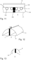
- FIG. 12 The Figures 12 and 13 explain a ninth embodiment of the invention. This shows Figure 12 an axonometric representation and Figure 13 a cross section.
- the ninth embodiment uses a reflector as already explained above with reference to the fifth embodiment.
- the reflector of the ninth embodiment can, for example, be semicircular or parabolic.
- the inside of the reflector 6 can be provided with an infrared-reflecting coating. This avoids the absorption of heat radiation and the heating of the reflector 6. This can improve the efficiency of the device according to the invention.
- the opening of the reflector 6 facing the room can either be open or closed with a surface element 31, as already mentioned above Figures 1 to 11 was explained in more detail.
- the device 1 which contains a heat sink with an interface. If the surface element 31 is not attached to the reflector 6, the device 1 has at least one surface element 31, which prevents the entry of moisture Room air to the interface 100 is prevented, as described above Figures 5 and 6 explained.
- the essential difference of the device 1 according to Figure 12 to the device 1 according to the Figures 5 and 6 is that the device 1 of the ninth embodiment of the invention does not have a circular cross-section, but rather a polygonal, preferably rectangular, cross-section.
- the larger axis of the rectangular cross section corresponds approximately to the height of the profile of the reflector 6. This feature has the effect that heat radiation falls on the heat sink regardless of the entrance angle. Since most heat loads emit thermal radiation diffusely, the cooling capacity of the ninth embodiment of the device can be greater than the cooling capacity of the fifth embodiment of the invention.
- Figure 14 shows a tenth embodiment of the invention. This embodiment is also similar to the fifth embodiment.
- the tenth embodiment also has a cylindrical heat sink 1, which is arranged at the focal point of a first reflector 61.
- the thermal radiation 20, which does not fall perpendicularly onto the first reflector 61, is not focused into the focal point and therefore does not reach the heat sink in the device 1.
- this heat radiation falls on a second reflector 62, which is arranged below the first reflector 61 and has a smaller radius.
- the radiation is therefore reflected at the second reflector 62 and thus reaches the interface of the heat sink within the device 1. In this way, the performance of the fifth embodiment can be increased or the effect can be improved.
- Figure 15 shows an eleventh embodiment of the device according to the invention in cross section.
- the eleventh embodiment has a device 1 with a heat sink and a interface facing the room, as described above.
- the interface and the heat sink are integrated in a wall 25, which can be designed, for example, as a drywall or in solid construction.
- a reflector 6 Adjacent to the upper edge of the device 1 there is a reflector 6, which has approximately the shape of a quarter circle or the shape of a half parabola. This means that the apex of the reflector 6 approximately coincides with the upper edge of the device 1. Thermal radiation 20, which falls from the room onto the inside of the reflector 6, is reflected onto the interface of the heat sink of the device 1 and absorbed there. As a result, good heat dissipation of the heat loads in room 2 can be achieved even with a small active interface.
- the wall 25 can be provided with an infrared-reflecting coating 250.
- heat radiation 20, which initially falls from the room onto the wall 25, can be reflected onto the inside of the reflector 6 in order to be removed from the room 2 in this way.
- the infrared-reflecting coating 250 can, for example, be applied to the wall 25 as wall paint and increases the acceptance range of the optical image formed from the device 1 and the reflector 6.
- the twelfth embodiment has a heat sink 10 which has two opposing interfaces 100a and 100b, as already shown in FIG Figures 2 and 3 described.
- Each interface 100a and 100b is protected from the ingress of moist room air by a surface element 31 and 32, each surface element being spaced from the interface 100a and 100b by a gap 310 and 320.
- the heat sink 10 is connected in a thermally conductive manner in its edge region to a coolant line 11, as already shown in FIG Figure 9 illustrated sixth embodiment was explained.
- the frame 134 can also contain or consist of a polymer material.
- the surface element 31 can be attached to the frame 134 in a simple manner by thermal joining.
- a laser welding process or a contact welding process can be used to heat the material of the frame 134 and the surface element 31 above the glass transition temperature in predeterminable spatial areas and thereby weld them.
- the frame 134 is attached to the edge composite 13 by a mechanical fixing device 135.
- the fixing device 135 may include, for example, a magnetic attachment or a snap closure.
- sealing elements may be present to prevent ambient air from penetrating into the gap 310 or 320.
- Figure 17 shows that the dehumidification device 4 has a first valve 421 and a second valve 422.
- the first valve 421 opens into a supply line 461, which opens into the gap 310.
- the second valve 422 is connected to a discharge line 462, which opens into the outside area or the surroundings of the device 1.
- a sorbent 45 is arranged between the two valves, for example a zeolite or silica gel, which can bind moisture from the ambient air.
- moisture can flow from the gap 310 through the supply line 461 into the sorbent 45 and be bound there.
- the valve 421 can be closed and the valve 422 can be opened.
- the moisture can be expelled from the sorbent 45 and leave the device through the discharge line 462.
- valve 422 is closed and the valve 421 is opened. This process can be continued cyclically so that the gap 310 is continually dried.
- Figure 18 shows the application of the first embodiment of the invention.
- a room 2 is shown with at least one wall 25 and a ceiling 24.
- a device 1 is attached to the ceiling 24 and has an interface 100 facing the room 2.
- Figure 18 shows an example of two people as heat load 29. These radiate heat radiation 20, which is essentially non-directional. The thermal radiation 20 can therefore, to a certain extent, reach the interface of the device 1 directly, be absorbed there and through that in the Line 110 circulating refrigerant is removed from room 2. Another part of the thermal radiation 20 can be reflected on surfaces of the room, for example a table top, and in this way reach the interface of the device 1. Finally shows Figure 18 the optional use of an infrared reflective coating 250 on the walls 25, so that radiation 20 reflected from the heat loads 29 can be reflected on floor and / or wall surfaces and in this way reaches the interface of the heat sink of the device 1.
- An optional control device 150 can be present in room 2, which prevents the heat loads 29 from cooling down too much.
- FIG 19 shows the application of the second embodiment of the invention.
- the same reference numbers designate the same components of the invention.
- the second embodiment of the invention has two opposing interfaces 100a and 100b, for example as shown in FIG Figure 2 was explained.
- the device 1 is therefore attached at a distance from the ceiling 24, so that a gap 248 is formed between the ceiling 24 and the interface above.
- Thermal radiation 20, which emanates from the heat loads 29, can therefore either reach the lower boundary surface or, through reflection on the walls 25 and the ceiling 24, the upper boundary surface. As a result, the performance of the device 1 when dissipating the heat from the heat load 29 can be increased.
- a device 1b used as a room divider which also has two boundary surfaces which face the right and left sides of the room. Thermal radiation from a heat load 29 can therefore also be absorbed at the interfaces of the second device 1b.
- the supply of refrigerant can take place via a refrigerant line 110b running in a cavity floor.
- Figure 20 shows the application of the ninth embodiment of the invention.
- the device 1 with the associated reflector 6 is attached to the ceiling 24.
- a fabric 251 may be present to provide a decorative appearance to the ceiling and to hide the reflector 6 from users.
- Thermal radiation either reaches the interfaces of the device 1 from the heat loads 29 directly via the reflector 6 or after reflection via an optional infrared-reflecting coating 250 on the walls 25.
- a refrigerant is available to dissipate heat from the heat sinks and is transported in a ceiling-mounted line 110 becomes.
- Figure 21 shows a further application of the first or second embodiment of the invention.
- either devices 1a with interfaces on both sides can be used or devices 1b with only one interface on one side.
- the devices 1a and 1b are mounted in a shaft 26, which is opened with an opening 261 to the space 2a and to the space 2b, respectively. Inside the shaft there are reflectors 262 which reflect thermal radiation 20, which enters through the opening 61, to the interface of the devices 1a and 1b. In order to avoid contamination and/or to enable a decorative appearance, the openings 261 are closed with an optional fabric 251. If the device 1a is arranged on an inner wall 25 between a room 2a and a room 2b, This can be used to cool the heat loads in both rooms.
- Figure 22 shows a tenth embodiment of the invention in cross section. The following description is limited to the essential differences from the previous embodiments. In this case too, the same reference numbers designate the same components of the invention.
- the device 1 also contains a heat sink 10 with at least one interface 100, as described above.
- the surface of the heat sink 10 opposite the interface 100 is provided with thermal insulation 120.
- the thermal insulation 120 can, for example, contain or consist of a rigid foam and/or a mineral wool and/or an organic insulation material.
- a tube register 11 is present in the exemplary embodiment shown, through which water or another known refrigerant can flow, for example.
- the pipe register removes heat from the heat sink during operation.
- the interface 100 faces the space 2, so that heat radiation from the space 2 can reach the interface 100 and is absorbed there.
- two surface elements 31 and 32 are present in the exemplary embodiment shown. These each include a gap 310 and 320.
- the surface elements 31 and 32 are at least partially transparent or translucent in the infrared spectral range of room temperature radiation, so that the thermal radiation from the room 2 can pass through the surface elements 31 and 32 and be absorbed by the interface 100. This allows the device to operate which, for example, can be designed as a cooling ceiling or wall element, even with high humidity and a large temperature difference, without causing moisture loss and subsequent mold problems or annoyance to users of the room.
- the surface elements 31 and 32 can, as described above, consist of glass or sintered, IR-transparent materials or plastic.
- Figure 22 further shows an edge composite 13, which accommodates the ends of the surface elements 31 and 32 and closes them in an approximately gas-tight manner, so that even at the edge, moisture from the environment cannot or can only penetrate to a small extent into the first gap 310 and the second gap 320.
- the interface 100 is provided with a fleece 160.
- This can rest loosely on the interface 100 or be attached to the interface, for example by gluing.
- the fleece 160 extends over the edge composite 13 to the back 121 of the thermal insulation 120.
- the fleece 160 can be attached over the entire surface or only cover a partial area 162 as shown in the figure.
- the reason for the suction of the fleece 160 lies in the surface tension of the fluid and in the wettability of the pore surfaces within the fleece 160. If the adhesion forces of liquid to the solid material become stronger than the molecular adhesion forces of the fluid, the capillary effect occurs.
- the capillary effect can be described very simply but well despite the complex pore structures.
- the capillary tensile forces accelerate the liquid in the pore.
- the flow resistance works against this.
- Gravity on the other hand, only has an influence on liquid transport from pore radii greater than 6 ⁇ m. In the cylinder capillary model, the capillary effect is divided into two temporal phases: suction and further distribution.
- the limit of the pore radius size is the balance of forces between flow resistance and capillary tensile forces.
- the flow resistance is proportional to the reciprocal of the radius of the pore squared, and the tensile force is simply proportional to the reciprocal of the radius.
- the second phase is further distribution after the water supply has been interrupted.
- the small pores that are not yet filled suck the larger pores empty.
- the water content in the front part decreases.
- the fleece thus absorbs the moisture inside the panel and distributes it over the entire fleece, beyond the edge connection to the outside 121 of the thermal insulation 120.
- the driving potential is the relative air humidity, which is lower on the warm side, ie on the outside 121 of the thermal insulation, than on the cold side, ie the interface 100.
- the gap 310 can be kept permanently dry in a simple manner and without moving parts in order to ensure long-term, trouble-free operation of the device.
Landscapes
- Engineering & Computer Science (AREA)
- Chemical & Material Sciences (AREA)
- Combustion & Propulsion (AREA)
- Mechanical Engineering (AREA)
- General Engineering & Computer Science (AREA)
- Life Sciences & Earth Sciences (AREA)
- Sustainable Development (AREA)
- Devices For Blowing Cold Air, Devices For Blowing Warm Air, And Means For Preventing Water Condensation In Air Conditioning Units (AREA)
- Cooling Or The Like Of Electrical Apparatus (AREA)
- Drying Of Gases (AREA)
Claims (15)
- Dispositif (1) comprenant au moins un dissipateur thermique (10) présentant au moins une surface limite (100) qui est tournée vers un local (2) et peut être amenée à une température abaissée par rapport à une charge thermique, au moins un élément surfacique (31, 32, 33, 34, 35, 36) étant disposé entre la surface limite (100) et le local (2), lequel est au moins partiellement perméable au rayonnement thermique, l'élément surfacique (31, 32, 33, 34, 35, 36) étant disposé à distance de la surface limite (100), de sorte qu'un espace intermédiaire (310, 320) est formé entre ledit au moins un élément surfacique (31, 32, 33, 34, 35, 36) et la surface limite (100), caractérisé en ce que ledit au moins un élément surfacique (31, 32, 33, 34, 35, 36) et le dissipateur thermique (10) sont bordés d'un bord composite (13) qui referme l'espace intermédiaire (310, 320) de façon pratiquement étanche aux gaz par rapport à l'environnement, et
en ce que le dispositif (1) comprend en outre au moins un organe de déshumidification (4) permettant d'éliminer l'eau de l'espace intermédiaire (310, 320) entre l'élément surfacique (31, 32) et la surface limite (100). - Dispositif selon la revendication 1,
caractérisé en ce que, à une longueur d'onde comprise entre environ 3 µm et environ 30 µm ou entre environ 6 µm et environ 20 µm, l'élément surfacique (31, 32, 33, 34, 35, 36) présente, au moins dans une zone partielle, une transmission supérieure à environ 50 % ou supérieure à environ 70 % ou supérieure à environ 80 %. - Dispositif selon la revendication 1 ou 2,
caractérisé en ce que le dissipateur thermique (10) comprend un registre tubulaire (11) et/ou un échangeur de chaleur à plaques. - Dispositif selon l'une des revendications 1 à 3,
caractérisé en ce qu'il comporte en outre un organe permettant de remplir l'espace intermédiaire (310, 320) avec un gaz protecteur ou de le mettre sous vide. - Dispositif selon l'une des revendications 1 à 4,
caractérisé en ce que l'organe de déshumidification (4) comprend ou est constitué d'au moins un agent de sorption (45) et/ou d'au moins une micro-pompe (46) et/ou d'au moins un organe de chauffage (44) et/ou d'au moins une vanne (41, 42) et/ou d'au moins un ventilateur et/ou d'un matériau poreux et/ou d'un non-tissé. - Dispositif selon l'une des revendications 1 à 5,caractérisé en ce que ledit au moins un élément surfacique (31, 32, 33, 34, 35, 36) contient ou est constitué d'un polymère, ouen ce que ledit au moins un élément surfacique (31, 32, 33, 34, 35, 36) contient ou est constitué de polyéthylène et/ou de polyméthylmétacrylate et/ou de polychlorure de vinyle et/ou de polypropylène et/ou de polyéthylène téréphtalate et/ou de polyester et/ou d'acétate butyrate de cellulose et/ou de polymère d'acétate de cellulose.
- Dispositif selon l'une des revendications 1 à 6,caractérisé en ce que le bord composite (13) comprend au moins un élément d'étanchéité (131) qui contient ou est constitué de polyisobutylène et/ou de silicone et/ou de caoutchouc butyle, ouen ce que le bord composite (13) entre ledit au moins un élément surfacique (31, 32, 33, 34, 35, 36) et le dissipateur thermique (10) peut être obtenu par assemblage thermique, ouen ce que le bord composite (13) présente des moyens d'obturation magnétiques ou mécaniques permettant de coupler ledit au moins un élément surfacique (31, 32, 33, 34, 35, 36) et le dissipateur thermique (10).
- Dispositif selon l'une des revendications 1 à 7,
comprenant en outre au moins un réflecteur (6, 61, 62) permettant de réfléchir le rayonnement thermique (20) vers au moins une surface limite (100). - Dispositif selon l'une des revendications 1 à 8,
caractérisé en ce que la surface limite (100) est au moins partiellement pourvue d'un non-tissé (160). - Dispositif selon la revendication 9,
caractérisé en ce que le non-tissé (160) s'étend sur le bord composite (13) jusqu'à la face arrière (121) de l'isolation thermique (120). - Procédé de climatisation d'un local (2), avec au moins un dissipateur thermique (10) qui présente au moins une surface limite (100) tournée vers le local, laquelle est amenée à une température abaissée par rapport à une charge thermique,dans lequel au moins un élément surfacique (31, 32, 33, 34, 35, 36) est disposé entre la surface limite (100) et le local (2), lequel est au moins partiellement perméable au rayonnement thermique, l'élément surfacique (31, 32, 33) étant disposé à distance de la surface limite (100), de sorte qu'un espace intermédiaire (310, 320, 330) est formé entre l'élément surfacique (31, 32, 33) et la surface limite (100),caractérisé en ce que ledit au moins un élément surfacique (31, 32, 33, 34, 35, 36) et le dissipateur thermique (10) sont bordés d'un bord composite (13) qui referme l'espace intermédiaire (310, 320, 330) de manière pratiquement étanche aux gaz par rapport à l'environnement, eten ce que l'espace intermédiaire (310, 320, 330) est déshumidifié.
- Procédé selon la revendication 11,
caractérisé en ce que, à une longueur d'onde du rayonnement thermique (20) comprise entre environ 6 µm et environ 20 µm, l'élément surfacique (31, 32, 33, 34, 35, 36) présente, dans au moins une zone partielle, une transmission d'environ 50 % à environ 90 %. - Procédé selon l'une des revendications 11 à 12,
caractérisé en ce que l'espace intermédiaire est rempli d'un gaz protecteur ou est mis sous vide. - Procédé selon l'une des revendications 11 à 13,
caractérisé en ce que la déshumidification est réalisée par au moins un non-tissé (160) qui est appliqué sur la surface limite (100) et qui élimine l'humidité de l'espace intermédiaire (310) par des forces de traction capillaires. - Procédé selon l'une des revendications 11 à 14,
caractérisé en ce que le rayonnement thermique (20) est réfléchi vers ladite au moins une surface limite (100) au moyen d'un réflecteur (6).
Applications Claiming Priority (2)
| Application Number | Priority Date | Filing Date | Title |
|---|---|---|---|
| DE102015211473.2A DE102015211473A1 (de) | 2015-06-22 | 2015-06-22 | Vorrichtung und Verfahren zur Klimatisierung eines Raumes |
| PCT/EP2016/064268 WO2016207141A2 (fr) | 2015-06-22 | 2016-06-21 | Dispositif et procédé de climatisation d'un espace |
Publications (3)
| Publication Number | Publication Date |
|---|---|
| EP3311077A2 EP3311077A2 (fr) | 2018-04-25 |
| EP3311077B1 true EP3311077B1 (fr) | 2024-03-13 |
| EP3311077C0 EP3311077C0 (fr) | 2024-03-13 |
Family
ID=56148411
Family Applications (1)
| Application Number | Title | Priority Date | Filing Date |
|---|---|---|---|
| EP16730411.2A Active EP3311077B1 (fr) | 2015-06-22 | 2016-06-21 | Dispositif et méthode pour la climatisation d'un espace |
Country Status (6)
| Country | Link |
|---|---|
| US (1) | US10371398B2 (fr) |
| EP (1) | EP3311077B1 (fr) |
| CN (1) | CN107995944B (fr) |
| DE (1) | DE102015211473A1 (fr) |
| SG (1) | SG11201710720SA (fr) |
| WO (1) | WO2016207141A2 (fr) |
Families Citing this family (8)
| Publication number | Priority date | Publication date | Assignee | Title |
|---|---|---|---|---|
| US10629515B2 (en) * | 2016-12-20 | 2020-04-21 | Xerox Corporation | System and method for cooling digital mirror devices |
| WO2019099834A1 (fr) * | 2017-11-16 | 2019-05-23 | The Trustees Of Princeton University | Procédé et appareil de rayonnement thermique |
| WO2020140196A1 (fr) * | 2019-01-02 | 2020-07-09 | 大连理工大学 | Système de climatisation à commande de rayonnement d'environnement sain et confortable en intérieur reposant sur une technologie de détection infrarouge |
| EP3911906A1 (fr) * | 2019-01-29 | 2021-11-24 | Faiveley Transport Leipzig GmbH & Co. KG | Échangeur de chaleur pour fluide de refroidissement combustible |
| DE102022112411A1 (de) | 2022-05-17 | 2023-11-23 | interpanel GmbH | Wärmetauscherpaneel zur Temperierung eines Raumes |
| DE102022128422A1 (de) * | 2022-10-27 | 2024-05-02 | Audi Aktiengesellschaft | Vorrichtung zum Erwärmen und/oder Desinfizieren, sowie Kraftfahrzeug mit einer solchen |
| US20240302106A1 (en) * | 2023-03-06 | 2024-09-12 | City University Of Hong Kong | Portable condensation-free temperature-adjustable radiant cooling board system |
| DE102023136386A1 (de) * | 2023-12-21 | 2025-06-26 | interpanel GmbH | Wärmetauscherpaneel zum Temperieren von Gebäuderäumen |
Citations (2)
| Publication number | Priority date | Publication date | Assignee | Title |
|---|---|---|---|---|
| US6263690B1 (en) * | 1999-08-06 | 2001-07-24 | Barcol-Air Ag | Apparatus for cooling a room |
| DE202011003135U1 (de) * | 2011-02-24 | 2011-06-09 | Köhler, Mario, 09337 | Klimatisierungselement |
Family Cites Families (15)
| Publication number | Priority date | Publication date | Assignee | Title |
|---|---|---|---|---|
| US3403723A (en) * | 1965-08-10 | 1968-10-01 | Lithonia Lighting Inc | Dynamically integrated comfort conditioning system |
| SE462583B (sv) * | 1988-11-25 | 1990-07-23 | Corroventa Ab | Saett och anordning foer avfuktning av luft |
| JPH06323577A (ja) * | 1993-05-14 | 1994-11-25 | Central Res Inst Of Electric Power Ind | 放射冷房装置 |
| CN1204284A (zh) * | 1995-12-15 | 1999-01-06 | 科莱姆康公司 | 空调系统用的换热器装置 |
| JPH09273776A (ja) * | 1996-04-04 | 1997-10-21 | Matsushita Electric Works Ltd | 天井輻射空調システム |
| JPH10205833A (ja) * | 1997-01-17 | 1998-08-04 | Sanyo Electric Co Ltd | 輻射式空気調和装置 |
| JPH10220825A (ja) * | 1997-02-05 | 1998-08-21 | Sanyo Electric Co Ltd | 輻射式空気調和装置 |
| JP2001355894A (ja) * | 2000-06-13 | 2001-12-26 | Yuuki:Kk | 輻射式空調システム |
| EP1489241A1 (fr) | 2003-06-20 | 2004-12-22 | Schneider Dämmtechnik AG | Système de fixation pour éléments de plafonds |
| JP2007132557A (ja) * | 2005-11-09 | 2007-05-31 | Sekisui Chem Co Ltd | 輻射空調パネル構造 |
| JP4816660B2 (ja) * | 2008-02-29 | 2011-11-16 | ダイキン工業株式会社 | 空気調和装置の室外ユニット |
| EP2169331A3 (fr) * | 2008-09-30 | 2010-07-28 | Aeteba GmbH | Unité de refroidissement solaire |
| DE102008053192A1 (de) * | 2008-10-24 | 2010-04-29 | Fraunhofer-Gesellschaft zur Förderung der angewandten Forschung e.V. | Solarkollektor mit Kühlfunktion |
| DE102010003462A1 (de) * | 2010-03-30 | 2011-10-06 | Bam Deutschland Ag | Temperiersystem |
| DE102013019741A1 (de) * | 2013-11-27 | 2015-06-11 | BeKa Heiz- und Kühlmatten GmbH | Klimaplatte für die Gestaltung einer Decken- und/oder Wandausführung |
-
2015
- 2015-06-22 DE DE102015211473.2A patent/DE102015211473A1/de active Pending
-
2016
- 2016-06-21 SG SG11201710720SA patent/SG11201710720SA/en unknown
- 2016-06-21 US US15/738,952 patent/US10371398B2/en active Active
- 2016-06-21 CN CN201680036960.0A patent/CN107995944B/zh active Active
- 2016-06-21 EP EP16730411.2A patent/EP3311077B1/fr active Active
- 2016-06-21 WO PCT/EP2016/064268 patent/WO2016207141A2/fr not_active Ceased
Patent Citations (2)
| Publication number | Priority date | Publication date | Assignee | Title |
|---|---|---|---|---|
| US6263690B1 (en) * | 1999-08-06 | 2001-07-24 | Barcol-Air Ag | Apparatus for cooling a room |
| DE202011003135U1 (de) * | 2011-02-24 | 2011-06-09 | Köhler, Mario, 09337 | Klimatisierungselement |
Also Published As
| Publication number | Publication date |
|---|---|
| EP3311077A2 (fr) | 2018-04-25 |
| CN107995944A (zh) | 2018-05-04 |
| SG11201710720SA (en) | 2018-01-30 |
| WO2016207141A3 (fr) | 2017-02-16 |
| US10371398B2 (en) | 2019-08-06 |
| CN107995944B (zh) | 2021-01-01 |
| WO2016207141A2 (fr) | 2016-12-29 |
| EP3311077C0 (fr) | 2024-03-13 |
| US20180172296A1 (en) | 2018-06-21 |
| DE102015211473A1 (de) | 2016-12-22 |
Similar Documents
| Publication | Publication Date | Title |
|---|---|---|
| EP3311077B1 (fr) | Dispositif et méthode pour la climatisation d'un espace | |
| EP3669127B1 (fr) | Élément d'échange de chaleur et procédé de fabrication dudit | |
| DE2239438C3 (de) | Zweischaliges Fassadenelement für Gebäude | |
| DD296140A5 (de) | Fenster-, wand-, dach- oder bruestungselement | |
| AT10282U1 (de) | Glasfassadenelement und elementglasfassade | |
| DE102015212924A1 (de) | Aktives Fenstermodul zur thermischen Regulierung eines Gebäudes und Verfahren | |
| EP4526603A1 (fr) | Panneau d'échangeur de chaleur pour réguler la température d'un espace | |
| DE4322653C2 (de) | Brüstungselement | |
| CH630458A5 (de) | Waermeaustauscher, insbesondere zum heizen oder kuehlen eines raumes, und verwendung des waermeaustauschers. | |
| EP4209722A1 (fr) | Système de régulation de température de locaux | |
| EP2896898B1 (fr) | Élément de façade avec accumulateur de chaleur latente, module d'accumulatuer de chaleur latente et procédé de climatisation d'un immeuble | |
| EP0626545A1 (fr) | Dispositif de chauffage passif solaire des batiments | |
| EP2463601A2 (fr) | Élément de fassade solaire, système der fassade solaire | |
| EP0133989A2 (fr) | Elément de construction, en particulier élément de mur en forme de panneau | |
| WO2011045086A1 (fr) | Dispositif convertisseur d'énergie pour une utilisation comme collecteur solaire ou comme corps de chauffage | |
| EP0181574A2 (fr) | Procédé de construction d'un revêtement de mur ou toiture d'un bâtiment ou autre servant de collecteur d'air pour une installation de pompe à chaleur | |
| DE4427947A1 (de) | Vorrichtung zur Entwärmung elektrischer und/oder elektronischer Geräte | |
| DE202020001781U1 (de) | Mehrschichtiges Dämmsystem zur Dämmung eines Gebäudes | |
| EP2792961B1 (fr) | Module d'échangeur de chaleur | |
| DE10204585B4 (de) | Sonnenkollektor zum vorzugsweisen Betrieb mit gasförmigen Medien | |
| DE10106776A1 (de) | Solarmodule sowie Verfahren zur Raumkühlung und Energiegewinnung | |
| DE3236726A1 (de) | Verfahren und vorrichtung zur technischen nutzung von sonnenenergie | |
| AT519364B1 (de) | Strahlungskühler für eine Gebäudekühlung | |
| DE2817345C2 (de) | Vorrichtung zum Temperieren von Räumen eines Gebäudes | |
| WO2025133145A1 (fr) | Panneau d'échangeur de chaleur pour réguler la température de salles de bâtiment |
Legal Events
| Date | Code | Title | Description |
|---|---|---|---|
| STAA | Information on the status of an ep patent application or granted ep patent |
Free format text: STATUS: THE INTERNATIONAL PUBLICATION HAS BEEN MADE |
|
| PUAI | Public reference made under article 153(3) epc to a published international application that has entered the european phase |
Free format text: ORIGINAL CODE: 0009012 |
|
| STAA | Information on the status of an ep patent application or granted ep patent |
Free format text: STATUS: REQUEST FOR EXAMINATION WAS MADE |
|
| 17P | Request for examination filed |
Effective date: 20180122 |
|
| AK | Designated contracting states |
Kind code of ref document: A2 Designated state(s): AL AT BE BG CH CY CZ DE DK EE ES FI FR GB GR HR HU IE IS IT LI LT LU LV MC MK MT NL NO PL PT RO RS SE SI SK SM TR |
|
| AX | Request for extension of the european patent |
Extension state: BA ME |
|
| RIN1 | Information on inventor provided before grant (corrected) |
Inventor name: LIERSCHOF, SOPHIE Inventor name: BUFF, ALEXANDER |
|
| DAV | Request for validation of the european patent (deleted) | ||
| DAX | Request for extension of the european patent (deleted) | ||
| STAA | Information on the status of an ep patent application or granted ep patent |
Free format text: STATUS: EXAMINATION IS IN PROGRESS |
|
| 17Q | First examination report despatched |
Effective date: 20210430 |
|
| RAP3 | Party data changed (applicant data changed or rights of an application transferred) |
Owner name: FRAUNHOFER-GESELLSCHAFT ZUR FOERDERUNG DER ANGEWANDTEN FORSCHUNG E.V. |
|
| GRAP | Despatch of communication of intention to grant a patent |
Free format text: ORIGINAL CODE: EPIDOSNIGR1 |
|
| STAA | Information on the status of an ep patent application or granted ep patent |
Free format text: STATUS: GRANT OF PATENT IS INTENDED |
|
| INTG | Intention to grant announced |
Effective date: 20231013 |
|
| GRAS | Grant fee paid |
Free format text: ORIGINAL CODE: EPIDOSNIGR3 |
|
| GRAA | (expected) grant |
Free format text: ORIGINAL CODE: 0009210 |
|
| STAA | Information on the status of an ep patent application or granted ep patent |
Free format text: STATUS: THE PATENT HAS BEEN GRANTED |
|
| AK | Designated contracting states |
Kind code of ref document: B1 Designated state(s): AL AT BE BG CH CY CZ DE DK EE ES FI FR GB GR HR HU IE IS IT LI LT LU LV MC MK MT NL NO PL PT RO RS SE SI SK SM TR |
|
| REG | Reference to a national code |
Ref country code: GB Ref legal event code: FG4D Free format text: NOT ENGLISH |
|
| REG | Reference to a national code |
Ref country code: CH Ref legal event code: EP |
|
| REG | Reference to a national code |
Ref country code: DE Ref legal event code: R096 Ref document number: 502016016417 Country of ref document: DE |
|
| REG | Reference to a national code |
Ref country code: IE Ref legal event code: FG4D Free format text: LANGUAGE OF EP DOCUMENT: GERMAN |
|
| U01 | Request for unitary effect filed |
Effective date: 20240408 |
|
| U07 | Unitary effect registered |
Designated state(s): AT BE BG DE DK EE FI FR IT LT LU LV MT NL PT SE SI Effective date: 20240416 |
|
| PG25 | Lapsed in a contracting state [announced via postgrant information from national office to epo] |
Ref country code: GR Free format text: LAPSE BECAUSE OF FAILURE TO SUBMIT A TRANSLATION OF THE DESCRIPTION OR TO PAY THE FEE WITHIN THE PRESCRIBED TIME-LIMIT Effective date: 20240614 |
|
| U20 | Renewal fee for the european patent with unitary effect paid |
Year of fee payment: 9 Effective date: 20240613 |
|
| PG25 | Lapsed in a contracting state [announced via postgrant information from national office to epo] |
Ref country code: RS Free format text: LAPSE BECAUSE OF FAILURE TO SUBMIT A TRANSLATION OF THE DESCRIPTION OR TO PAY THE FEE WITHIN THE PRESCRIBED TIME-LIMIT Effective date: 20240613 Ref country code: HR Free format text: LAPSE BECAUSE OF FAILURE TO SUBMIT A TRANSLATION OF THE DESCRIPTION OR TO PAY THE FEE WITHIN THE PRESCRIBED TIME-LIMIT Effective date: 20240313 |
|
| PG25 | Lapsed in a contracting state [announced via postgrant information from national office to epo] |
Ref country code: ES Free format text: LAPSE BECAUSE OF FAILURE TO SUBMIT A TRANSLATION OF THE DESCRIPTION OR TO PAY THE FEE WITHIN THE PRESCRIBED TIME-LIMIT Effective date: 20240313 |
|
| PG25 | Lapsed in a contracting state [announced via postgrant information from national office to epo] |
Ref country code: RS Free format text: LAPSE BECAUSE OF FAILURE TO SUBMIT A TRANSLATION OF THE DESCRIPTION OR TO PAY THE FEE WITHIN THE PRESCRIBED TIME-LIMIT Effective date: 20240613 Ref country code: NO Free format text: LAPSE BECAUSE OF FAILURE TO SUBMIT A TRANSLATION OF THE DESCRIPTION OR TO PAY THE FEE WITHIN THE PRESCRIBED TIME-LIMIT Effective date: 20240613 Ref country code: HR Free format text: LAPSE BECAUSE OF FAILURE TO SUBMIT A TRANSLATION OF THE DESCRIPTION OR TO PAY THE FEE WITHIN THE PRESCRIBED TIME-LIMIT Effective date: 20240313 Ref country code: GR Free format text: LAPSE BECAUSE OF FAILURE TO SUBMIT A TRANSLATION OF THE DESCRIPTION OR TO PAY THE FEE WITHIN THE PRESCRIBED TIME-LIMIT Effective date: 20240614 Ref country code: ES Free format text: LAPSE BECAUSE OF FAILURE TO SUBMIT A TRANSLATION OF THE DESCRIPTION OR TO PAY THE FEE WITHIN THE PRESCRIBED TIME-LIMIT Effective date: 20240313 |
|
| PG25 | Lapsed in a contracting state [announced via postgrant information from national office to epo] |
Ref country code: IS Free format text: LAPSE BECAUSE OF FAILURE TO SUBMIT A TRANSLATION OF THE DESCRIPTION OR TO PAY THE FEE WITHIN THE PRESCRIBED TIME-LIMIT Effective date: 20240713 |
|
| PG25 | Lapsed in a contracting state [announced via postgrant information from national office to epo] |
Ref country code: SM Free format text: LAPSE BECAUSE OF FAILURE TO SUBMIT A TRANSLATION OF THE DESCRIPTION OR TO PAY THE FEE WITHIN THE PRESCRIBED TIME-LIMIT Effective date: 20240313 |
|
| PG25 | Lapsed in a contracting state [announced via postgrant information from national office to epo] |
Ref country code: CZ Free format text: LAPSE BECAUSE OF FAILURE TO SUBMIT A TRANSLATION OF THE DESCRIPTION OR TO PAY THE FEE WITHIN THE PRESCRIBED TIME-LIMIT Effective date: 20240313 |
|
| PG25 | Lapsed in a contracting state [announced via postgrant information from national office to epo] |
Ref country code: PL Free format text: LAPSE BECAUSE OF FAILURE TO SUBMIT A TRANSLATION OF THE DESCRIPTION OR TO PAY THE FEE WITHIN THE PRESCRIBED TIME-LIMIT Effective date: 20240313 |
|
| PG25 | Lapsed in a contracting state [announced via postgrant information from national office to epo] |
Ref country code: SK Free format text: LAPSE BECAUSE OF FAILURE TO SUBMIT A TRANSLATION OF THE DESCRIPTION OR TO PAY THE FEE WITHIN THE PRESCRIBED TIME-LIMIT Effective date: 20240313 |
|
| PG25 | Lapsed in a contracting state [announced via postgrant information from national office to epo] |
Ref country code: SM Free format text: LAPSE BECAUSE OF FAILURE TO SUBMIT A TRANSLATION OF THE DESCRIPTION OR TO PAY THE FEE WITHIN THE PRESCRIBED TIME-LIMIT Effective date: 20240313 Ref country code: SK Free format text: LAPSE BECAUSE OF FAILURE TO SUBMIT A TRANSLATION OF THE DESCRIPTION OR TO PAY THE FEE WITHIN THE PRESCRIBED TIME-LIMIT Effective date: 20240313 Ref country code: RO Free format text: LAPSE BECAUSE OF FAILURE TO SUBMIT A TRANSLATION OF THE DESCRIPTION OR TO PAY THE FEE WITHIN THE PRESCRIBED TIME-LIMIT Effective date: 20240313 Ref country code: PL Free format text: LAPSE BECAUSE OF FAILURE TO SUBMIT A TRANSLATION OF THE DESCRIPTION OR TO PAY THE FEE WITHIN THE PRESCRIBED TIME-LIMIT Effective date: 20240313 Ref country code: IS Free format text: LAPSE BECAUSE OF FAILURE TO SUBMIT A TRANSLATION OF THE DESCRIPTION OR TO PAY THE FEE WITHIN THE PRESCRIBED TIME-LIMIT Effective date: 20240713 Ref country code: CZ Free format text: LAPSE BECAUSE OF FAILURE TO SUBMIT A TRANSLATION OF THE DESCRIPTION OR TO PAY THE FEE WITHIN THE PRESCRIBED TIME-LIMIT Effective date: 20240313 |
|
| REG | Reference to a national code |
Ref country code: DE Ref legal event code: R097 Ref document number: 502016016417 Country of ref document: DE |
|
| PLBE | No opposition filed within time limit |
Free format text: ORIGINAL CODE: 0009261 |
|
| STAA | Information on the status of an ep patent application or granted ep patent |
Free format text: STATUS: NO OPPOSITION FILED WITHIN TIME LIMIT |
|
| PG25 | Lapsed in a contracting state [announced via postgrant information from national office to epo] |
Ref country code: MC Free format text: LAPSE BECAUSE OF FAILURE TO SUBMIT A TRANSLATION OF THE DESCRIPTION OR TO PAY THE FEE WITHIN THE PRESCRIBED TIME-LIMIT Effective date: 20240313 |
|
| REG | Reference to a national code |
Ref country code: CH Ref legal event code: PL |
|
| 26N | No opposition filed |
Effective date: 20241216 |
|
| GBPC | Gb: european patent ceased through non-payment of renewal fee |
Effective date: 20240621 |
|
| PG25 | Lapsed in a contracting state [announced via postgrant information from national office to epo] |
Ref country code: IE Free format text: LAPSE BECAUSE OF NON-PAYMENT OF DUE FEES Effective date: 20240621 |
|
| PG25 | Lapsed in a contracting state [announced via postgrant information from national office to epo] |
Ref country code: CH Free format text: LAPSE BECAUSE OF NON-PAYMENT OF DUE FEES Effective date: 20240630 |
|
| PG25 | Lapsed in a contracting state [announced via postgrant information from national office to epo] |
Ref country code: GB Free format text: LAPSE BECAUSE OF NON-PAYMENT OF DUE FEES Effective date: 20240621 |
|
| U20 | Renewal fee for the european patent with unitary effect paid |
Year of fee payment: 10 Effective date: 20250623 |
|
| PG25 | Lapsed in a contracting state [announced via postgrant information from national office to epo] |
Ref country code: CY Free format text: LAPSE BECAUSE OF FAILURE TO SUBMIT A TRANSLATION OF THE DESCRIPTION OR TO PAY THE FEE WITHIN THE PRESCRIBED TIME-LIMIT; INVALID AB INITIO Effective date: 20160621 |
|
| PG25 | Lapsed in a contracting state [announced via postgrant information from national office to epo] |
Ref country code: HU Free format text: LAPSE BECAUSE OF FAILURE TO SUBMIT A TRANSLATION OF THE DESCRIPTION OR TO PAY THE FEE WITHIN THE PRESCRIBED TIME-LIMIT; INVALID AB INITIO Effective date: 20160621 |