EP3311648A2 - Mäher mit null-wenderadius - Google Patents
Mäher mit null-wenderadius Download PDFInfo
- Publication number
- EP3311648A2 EP3311648A2 EP17185789.9A EP17185789A EP3311648A2 EP 3311648 A2 EP3311648 A2 EP 3311648A2 EP 17185789 A EP17185789 A EP 17185789A EP 3311648 A2 EP3311648 A2 EP 3311648A2
- Authority
- EP
- European Patent Office
- Prior art keywords
- output shaft
- gearbox
- mower
- turning radius
- vertical output
- Prior art date
- Legal status (The legal status is an assumption and is not a legal conclusion. Google has not performed a legal analysis and makes no representation as to the accuracy of the status listed.)
- Granted
Links
Images


Classifications
-
- B—PERFORMING OPERATIONS; TRANSPORTING
- B60—VEHICLES IN GENERAL
- B60K—ARRANGEMENT OR MOUNTING OF PROPULSION UNITS OR OF TRANSMISSIONS IN VEHICLES; ARRANGEMENT OR MOUNTING OF PLURAL DIVERSE PRIME-MOVERS IN VEHICLES; AUXILIARY DRIVES FOR VEHICLES; INSTRUMENTATION OR DASHBOARDS FOR VEHICLES; ARRANGEMENTS IN CONNECTION WITH COOLING, AIR INTAKE, GAS EXHAUST OR FUEL SUPPLY OF PROPULSION UNITS IN VEHICLES
- B60K11/00—Arrangement in connection with cooling of propulsion units
- B60K11/06—Arrangement in connection with cooling of propulsion units with air cooling
-
- A—HUMAN NECESSITIES
- A01—AGRICULTURE; FORESTRY; ANIMAL HUSBANDRY; HUNTING; TRAPPING; FISHING
- A01D—HARVESTING; MOWING
- A01D69/00—Driving mechanisms or parts thereof for harvesters or mowers
- A01D69/06—Gearings
-
- B—PERFORMING OPERATIONS; TRANSPORTING
- B60—VEHICLES IN GENERAL
- B60K—ARRANGEMENT OR MOUNTING OF PROPULSION UNITS OR OF TRANSMISSIONS IN VEHICLES; ARRANGEMENT OR MOUNTING OF PLURAL DIVERSE PRIME-MOVERS IN VEHICLES; AUXILIARY DRIVES FOR VEHICLES; INSTRUMENTATION OR DASHBOARDS FOR VEHICLES; ARRANGEMENTS IN CONNECTION WITH COOLING, AIR INTAKE, GAS EXHAUST OR FUEL SUPPLY OF PROPULSION UNITS IN VEHICLES
- B60K17/00—Arrangement or mounting of transmissions in vehicles
- B60K17/04—Arrangement or mounting of transmissions in vehicles characterised by arrangement, location or kind of gearing
- B60K17/06—Arrangement or mounting of transmissions in vehicles characterised by arrangement, location or kind of gearing of change-speed gearing
- B60K17/08—Arrangement or mounting of transmissions in vehicles characterised by arrangement, location or kind of gearing of change-speed gearing of mechanical type
-
- B—PERFORMING OPERATIONS; TRANSPORTING
- B60—VEHICLES IN GENERAL
- B60K—ARRANGEMENT OR MOUNTING OF PROPULSION UNITS OR OF TRANSMISSIONS IN VEHICLES; ARRANGEMENT OR MOUNTING OF PLURAL DIVERSE PRIME-MOVERS IN VEHICLES; AUXILIARY DRIVES FOR VEHICLES; INSTRUMENTATION OR DASHBOARDS FOR VEHICLES; ARRANGEMENTS IN CONNECTION WITH COOLING, AIR INTAKE, GAS EXHAUST OR FUEL SUPPLY OF PROPULSION UNITS IN VEHICLES
- B60K5/00—Arrangement or mounting of internal-combustion or jet-propulsion units
- B60K5/04—Arrangement or mounting of internal-combustion or jet-propulsion units with the engine main axis, e.g. crankshaft axis, transversely to the longitudinal centre line of the vehicle
-
- F—MECHANICAL ENGINEERING; LIGHTING; HEATING; WEAPONS; BLASTING
- F16—ENGINEERING ELEMENTS AND UNITS; GENERAL MEASURES FOR PRODUCING AND MAINTAINING EFFECTIVE FUNCTIONING OF MACHINES OR INSTALLATIONS; THERMAL INSULATION IN GENERAL
- F16H—GEARING
- F16H57/00—General details of gearing
- F16H57/02—Gearboxes; Mounting gearing therein
- F16H57/027—Gearboxes; Mounting gearing therein characterised by means for venting gearboxes, e.g. air breathers
-
- A—HUMAN NECESSITIES
- A01—AGRICULTURE; FORESTRY; ANIMAL HUSBANDRY; HUNTING; TRAPPING; FISHING
- A01D—HARVESTING; MOWING
- A01D2101/00—Lawn-mowers
-
- B—PERFORMING OPERATIONS; TRANSPORTING
- B60—VEHICLES IN GENERAL
- B60Y—INDEXING SCHEME RELATING TO ASPECTS CROSS-CUTTING VEHICLE TECHNOLOGY
- B60Y2200/00—Type of vehicle
- B60Y2200/20—Off-Road Vehicles
- B60Y2200/22—Agricultural vehicles
- B60Y2200/223—Ridable lawn mowers
Definitions
- This invention relates to zero turning radius (“ZTR”) mowers having rear mounted engines and independently powered left and right drive wheels controlled with hydrostatic transmissions.
- ZTR zero turning radius
- Zero turning radius (“ZTR”) mowers have at least one independently powered drive wheel on each side of a frame. Hydrostatic transmissions transmit power to each of the left and right drive wheels, either in forward or reverse.
- the pair of hydrostatic transmissions, or dual hydrostatic transmission may be driven by an internal combustion engine.
- the independent rear drive wheels allow the ZTR mower to turn on a vertical turning axis.
- the vertical turning axis may be centrally located between the pair of hydrostatic transmissions.
- ZTR mowers have frames with left and right longitudinal frame members supported on a forward end by front wheels and extending rearwardly to support an internal combustion engine.
- a mower deck may be suspended between the front and rear wheels.
- a seated operator may use left and right control levers or other steering controls to control the pair of hydrostatic transmissions driving the left and right rear drive wheels.
- ZTR mowers Internal combustion engines on ZTR mowers are mounted on the mower frame or platform behind the operator seat and rear wheels. Many ZTR mowers have internal combustion engines with vertical drive shafts. Pulleys on the vertical drive shafts drive belts that transmit power from the engine to the pair of hydrostatic transmissions with vertical shafts, and transmit power from the engine to pulleys on vertical shafts of a mower deck.
- ZTR mowers with vertical shaft engines include US Patents 5816034 for "Belt Design for Mower,” 6952913 for “Adjustable Belt Pulley System,” 7596934 for “Lawn Mower with Belt Drive System,” 7717219 for “Unitary Rear Frame for Mounting Engine, Hydrostatic Transmission, and Other Components to Mower,” and 7913479 for "Two-Pulley Belt Tensioning Mechanism.”
- mule drives are typically used.
- Mule drives include one or more belts that are driven by a pulley on the engine's horizontal drive shaft, twisting the belt to engage pulleys on vertical shafts of the hydrostatic transmissions and mower deck.
- ZTR mowers with horizontal drive shafts and mule drives examples include US Patents 5865020 for "Lawn Mower Having a Lower Center of Gravity," 6651413 for “Multiple Belt Mule Drive Apparatus and Systems/Vehicles Using Same,” 7427247 for “Mower Incorporating a Mule Drive,” and 7665284 and 7856799 for "Belt Drive for Lawn Mowers.”
- ZTR mowers with horizontal shaft engine are typically longer than ZTR mowers with vertical shaft engines, because the engines and mule drives extend farther behind the operator seat.
- Horizontal drive shaft engines and mule drives may extend rearwardly outside the ZTR mower's turning radius or turning circle, reducing the maneuverability of the ZTR mower, especially when mowing close to obstacles.
- a ZTR mower is needed with a horizontal drive shaft engine, but without the engine or mule drive extending rearwardly outside the ZTR mower's turning radius or turning circle. Additionally, mule drives require substantial distance and space between the horizontal and vertical shafts in order to twist the belts.
- a ZTR mower is needed with a horizontal engine that does not require a mule drive.
- Gearboxes may be used to convert a horizontal shaft drive to a vertical shaft drive.
- conventional gearboxes have gaseous pressure that builds up inside the gearbox as temperatures increase.
- spring-loaded vents have been used to vent gearboxes to atmosphere, with venting parts extending out through the gearbox wall. These vents present packaging issues, and may require cutting or modifying the mower frame next to the gearbox wall where the vent is located.
- a ZTR mower is needed with a gearbox vent having fewer parts and lower cost than conventional spring-loaded gearbox vents, lower risk of damage during assembly or operation, and reduced or eliminated packaging issues.
- a zero turning radius mower includes an internal combustion engine having a flywheel rotating on a horizontal axis and connected to an input shaft of a right angle gearbox.
- a pair of hydrostatic transmissions are driven by a belt engaged to an output shaft of the gearbox.
- a mower deck also is driven by the belt.
- the engine and gearbox are mounted to a frame within a turning circle having a vertical axis between the pair of hydrostatic transmissions and a perimeter at an outer edge of the pair of rear traction drive tires.
- a vent passage is provided through the output shaft of the gearbox, and a rotary fan having a central hub also is mounted to the output shaft.
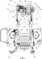
- zero turning radius (“ZTR") mower 100 has a rear drive wheel 102, 104 on each side of the vehicle that is powered to rotate independently of the other rear drive wheel.
- the independent rear drive wheels allow the ZTR mower to turn on vertical turning axis 106.
- the vertical turning axis may be centrally located between a pair of hydrostatic transmissions 108, 110 for the rear drive wheels.
- the hydrostatic transmissions may be compact integrated zero turn transaxles.
- the ZTR mower may turn around on central turning axis 106, in which radius 112 and perimeter 113 are defined by the rear drive wheels and tires.
- ZTR mower 100 may have frame 114 with left and right longitudinal frame members 116, 118 supported on a forward end by front wheels 120, 122 and extending rearwardly past operator seat 165 and rear drive wheels 102, 104 where the longitudinal frame members terminate and connect to rear cross member 134.
- Mower deck 124 may be suspended from the frame between the front and rear wheels.
- a seated operator may use left and right control levers 126, 128 or other steering controls, to control the pair of hydrostatic transmissions driving the left and right rear drive wheels.
- internal combustion engine 130 may be mounted transversely on the ZTR mower frame behind and rearwardly of operator seat 165 and rear drive wheels 102, 104.
- the transversely mounted engine may have flywheel 131 rotating on horizontal axis 129 oriented from right to left across the frame of the ZTR mower, perpendicular to the left and right longitudinal frame members.
- the transversely mounted engine may be mounted with engine mounts on longitudinal frame members 116, 118 and one or more cross members 134.
- the transversely mounted engine, and left and right longitudinal frame members and cross members supporting the engine are located inside or within the perimeter 113 of radius 112. This enables the ZTR mower to turn around and reverse direction while mowing close to obstacles.
- gearbox 136 may be mounted to the drive shaft or flywheel 131 and may convert the engine's horizontal rotational axis 129 to a vertical rotational axis for common belt drive 138.
- the common belt drive may power the rear drive wheels through the pair of hydrostatic transmissions 108, 110 and power the rotary cutting blades of the mower deck through jackshaft assembly 140.
- the gearbox may be a right angle gearbox mounted in bracket 142, which may be attached to the outside of longitudinal frame member 116, but inside perimeter 113 of radius 112.
- common belt drive 138 may include a pair of rubber V-belts 144, 146 driven by double pulley 148 secured to the lower end of the gearbox's vertical output shaft 150.
- the same belt or pair of belts may engage pulleys 152, 154 on vertical shafts on each of the hydrostatic transmissions, and pulley 156 on the vertical shaft of jackshaft assembly 140.
- the common belt drive may include three rubber V-belts driven by three pulleys mounted to the lower end of the gearbox's vertical output shaft.
- the jackshaft assembly may include a deck drive clutch that may be engaged and disengaged by an electrical switch. Rubber belt 158 may connect the jackshaft assembly to one or more deck drive pulleys on vertical spindles that rotate a plurality of rotary cutting blades under the mower deck.
- gearbox 136 may include spiral bevel gears 160, 162 on horizontal input shaft 164 and vertical output shaft 150.
- the spiral bevel gears and shafts may be disposed at right angles to each other, to change the transmitting direction from the generally horizontal axis of the engine drive shaft to the vertical axis of the common belt drive.
- the gearbox also may form an oil sump so that the shafts and gears may be adequately coated with lubricating oil while they rotate.
- coupler 166 may connect the engine flywheel 131 or horizontal drive shaft to the gearbox's horizontal input shaft 164.
- the input shaft may be supported for rotation by bearings 168, 170, and seals that engage the cylindrical surface of the input shaft to prevent leakage of oil or entry of contaminants.
- Spiral bevel gear 160 may be secured to the input shaft with nut 172.
- Vertical output shaft 150 may extend through the top and bottom of the gearbox, and may be supported for rotation by upper and lower bearings 174, 176, and upper and lower seals that engage and seal the cylindrical surface of the output shaft.
- Spiral bevel gear 162 may be secured to the gearbox's vertical output shaft between the upper and lower bearings.
- gearbox 136 may include gearbox vent 175 through vertical output shaft 150.
- the gearbox vent may be provided through the vertical output shaft to allow internal gearbox pressures to vent to atmosphere, and to prevent high internal pressures from causing seals in the gearbox to burst or leak.
- the gearbox vent through the vertical output shaft also eliminates the need for a conventional spring-loaded vent, which requires space on the gearbox housing, adds costs and can be damaged easily.
- gearbox vent 175 may include radial vent passage 178 connected to an axial vent passage 180.
- the radial vent passage may be a cross drilled hole through the diameter of the vertical output shaft, and the axial vent passage may connect the radial vent hole with the top end 182 of the vertical output shaft.
- gaseous internal pressures in the gearbox may pass around upper bearing 174.
- Radial vent passage 178 may be positioned above upper bearing 174, so that the upper bearing may protect and shield the vent passage from direct oil splash, oil migration and debris clogging.
- the internal pressures must pass around bolt 184 which secures rotary cooling fan 190 to the vertical output shaft.
- An air passage may be provided between the bolt threads and the internal threads of axial vent passage 180.
- bolt 184 may have flats 186, 188 on its opposing sides that prevent the threads from sealing the joint.
- a banjo bolt instead of a flat-sided bolt, a banjo bolt may be used, having a cross drilled hole through its diameter and an axial hole between the cross drilled hole and its threaded end.
- Passage 208 may include a radial gap and an axial gap between the central hub and vertical output shaft.
- central hub 196 may have an oblong or rectangular opening that fits onto a pair of flats 192, 194 on the top end of the vertical output shaft, so the central hub may seat on the vertical output shaft's shoulders 202, 204.
- the radial gap may be a pair of slots 198, 200 that extend radially out from the central hub past the vertical output shaft's shoulders, forming air vents between the central hub and vertical output shaft's outer circumference.
- the axial gap may be between the central hub and the vertical output shaft's top end.
- the axial gap may be provided by positioning washer 206 on the central hub between bolt 184 and the vertical output shaft's top end 182.
- gearbox vent 175 may be configured to prevent oil from entering and clogging any of the vent passages.
- the diameter of the vent passages may be sufficiently large to inhibit capillary oil migration, and preferably the diameter of each vent passage may be at least about 3 mm. Additionally, centrifugal forces of the spinning vertical output shaft may throw oil outward away from the vent passages.
Landscapes
- Engineering & Computer Science (AREA)
- Mechanical Engineering (AREA)
- Chemical & Material Sciences (AREA)
- Combustion & Propulsion (AREA)
- Transportation (AREA)
- General Engineering & Computer Science (AREA)
- Life Sciences & Earth Sciences (AREA)
- Environmental Sciences (AREA)
- Harvester Elements (AREA)
- Arrangement Or Mounting Of Propulsion Units For Vehicles (AREA)
Applications Claiming Priority (1)
| Application Number | Priority Date | Filing Date | Title |
|---|---|---|---|
| US15/248,298 US9789759B1 (en) | 2016-08-26 | 2016-08-26 | Zero turning radius mower |
Publications (3)
| Publication Number | Publication Date |
|---|---|
| EP3311648A2 true EP3311648A2 (de) | 2018-04-25 |
| EP3311648A3 EP3311648A3 (de) | 2018-10-31 |
| EP3311648B1 EP3311648B1 (de) | 2020-09-02 |
Family
ID=59581800
Family Applications (1)
| Application Number | Title | Priority Date | Filing Date |
|---|---|---|---|
| EP17185789.9A Active EP3311648B1 (de) | 2016-08-26 | 2017-08-10 | Mäher mit null-wenderadius |
Country Status (2)
| Country | Link |
|---|---|
| US (1) | US9789759B1 (de) |
| EP (1) | EP3311648B1 (de) |
Families Citing this family (6)
| Publication number | Priority date | Publication date | Assignee | Title |
|---|---|---|---|---|
| DE112017000741T5 (de) * | 2016-02-10 | 2018-11-15 | Magna Powertrain Of America, Inc. | Kraftübertragungsanordnung mit einem eine optimierte Ritzeleinheit aufweisenden Hypoidgetriebe |
| US10005358B2 (en) * | 2016-08-26 | 2018-06-26 | Deere & Company | Zero turning radius mower |
| US12296694B2 (en) | 2021-03-10 | 2025-05-13 | Techtronic Cordless Gp | Lawnmowers |
| DE102021131216B3 (de) * | 2021-11-29 | 2023-03-09 | Schaeffler Technologies AG & Co. KG | Gehäuse für eine Antriebseinheit, mit einer Entlüftungsschnittstelle und Antriebseinheit |
| USD1015381S1 (en) | 2022-02-14 | 2024-02-20 | Techtronic Cordless Gp | Lawn mower |
| USD1014568S1 (en) | 2022-02-14 | 2024-02-13 | Techtronic Cordless Gp | Lawn mower |
Citations (6)
| Publication number | Priority date | Publication date | Assignee | Title |
|---|---|---|---|---|
| US5816034A (en) | 1996-07-12 | 1998-10-06 | Peter; Timothy Jon | Belt design for mower |
| US5865020A (en) | 1995-11-16 | 1999-02-02 | Exmark Mfg. Co. | Lawn mower having a low center of gravity |
| US6952913B1 (en) | 2004-05-13 | 2005-10-11 | Auburn Consolidated Industries, Inc. | Adjustable belt pulley system |
| US7596934B2 (en) | 2006-08-11 | 2009-10-06 | Wright Manufacturing, Inc. | Lawn mower with belt drive system |
| US7717219B2 (en) | 2007-06-07 | 2010-05-18 | Deere & Company | Unitary rear frame for mounting engine, hydrostatic transmission, and other components to mower |
| US7913479B2 (en) | 2007-06-08 | 2011-03-29 | Mtd Products Inc | Two-pulley belt tensioning mechanism |
Family Cites Families (35)
| Publication number | Priority date | Publication date | Assignee | Title |
|---|---|---|---|---|
| US1974803A (en) | 1931-05-25 | 1934-09-25 | Wright Aeronautical Corp | Venting of crank cases |
| US2872831A (en) | 1958-01-02 | 1959-02-10 | Wood Brothers Mfg Company | Belt drive for multiple spindle tractor attachments |
| GB1181125A (en) * | 1967-06-02 | 1970-02-11 | Humber Ltd | Improvements in or relating to Breathing Devices for Closed Gear Housings |
| FR2098950A5 (de) * | 1970-07-31 | 1972-03-10 | Roques Et Lecoeur | |
| US3848691A (en) | 1972-11-30 | 1974-11-19 | Chrysler Corp | Full time four wheel drive |
| US3925970A (en) | 1974-06-24 | 1975-12-16 | Easborn Rusco | Lawnmower |
| US4221279A (en) | 1978-12-11 | 1980-09-09 | Dana Corporation | Centrifugal lubrication system for transmission pocket bearing |
| US4328659A (en) | 1980-06-09 | 1982-05-11 | Outboard Marine Corporation | Riding mower including belt drive system |
| DE3048364A1 (de) * | 1980-12-20 | 1982-07-29 | Gutbrod-Werke GmbH, 6601 Bübingen | Vorrichtung zur behandlung von gruenflaechen, insbesondere rasenflaechen |
| NL8203461A (nl) * | 1982-09-06 | 1984-04-02 | Lely Nv C Van Der | Maaiinrichting voor landbouwdoeleinden. |
| US4756208A (en) * | 1986-01-08 | 1988-07-12 | Kubota, Ltd. | Mid-mount tractor |
| US4768997A (en) | 1987-03-10 | 1988-09-06 | Tecumseh Products Company | Belt drive system for dual input transmissions/transaxles |
| US4987795A (en) * | 1989-11-03 | 1991-01-29 | Sundstrand Corporation | Vented transmission |
| US5373697A (en) * | 1991-07-22 | 1994-12-20 | Tecumseh Products Company | Hydraulic fluid system and dump valve mechanism for a hydrostatic transaxle |
| US5361566A (en) | 1993-05-05 | 1994-11-08 | Deere & Company | Implement belt drive mechanism |
| JPH07150925A (ja) * | 1993-12-02 | 1995-06-13 | Tochigi Fuji Ind Co Ltd | ブリーザ |
| US5911793A (en) * | 1997-05-22 | 1999-06-15 | Kaye; Kenneth B. | Transmission with semi-floating shafts |
| US6578656B2 (en) * | 1998-09-03 | 2003-06-17 | Kubota Corporation | Riding mower |
| US6651413B2 (en) | 2001-07-02 | 2003-11-25 | Exmark Manufacturing Company, Incorporated | Multiple belt mule drive apparatus and systems/vehicles using same |
| DE10132739A1 (de) * | 2001-07-05 | 2003-01-16 | Deere & Co | Entlüftungseinrichtung für ein Getriebegehäuse |
| US6951091B2 (en) | 2002-09-03 | 2005-10-04 | Norihiro Ishii | Riding lawn mower |
| JP4123925B2 (ja) | 2002-12-10 | 2008-07-23 | いすゞ自動車株式会社 | 変速機の潤滑構造 |
| US7047713B2 (en) * | 2004-01-22 | 2006-05-23 | Deere & Company | Low profile gearbox housing |
| US7427247B2 (en) | 2004-07-30 | 2008-09-23 | Briggs And Stratton Corporation | Mower incorporating a mule drive |
| US20090025997A1 (en) * | 2005-05-18 | 2009-01-29 | Norihiro Ishii | Hydraulic Drive Vehicle with Cooling System |
| US7726126B1 (en) * | 2005-12-21 | 2010-06-01 | Hydro-Gear Limited Partnership | Dual pump apparatus with power take off |
| DE102006005354A1 (de) | 2006-02-07 | 2007-08-09 | Deere & Company, Moline | Getriebeanordnung |
| EP1985487B1 (de) * | 2007-04-24 | 2018-08-08 | Kanzaki Kokyukoki Mfg. Co., Ltd. | Selbstfahrender Rasenmäher |
| US7665284B1 (en) | 2007-10-16 | 2010-02-23 | Excel Industries, Inc. | Belt drive for lawn mowers |
| US8984871B1 (en) * | 2010-12-23 | 2015-03-24 | Hydro-Gear Limited Partnership | Transmission assembly |
| DE112012000684T5 (de) * | 2011-03-31 | 2013-11-28 | Aisin Aw Co., Ltd. | Leistungsübertragungseinrichtung |
| US9155246B2 (en) | 2012-10-22 | 2015-10-13 | Kubota Corporation | Riding type mower |
| US20150204434A1 (en) * | 2014-01-22 | 2015-07-23 | Deere & Company | High speed gearbox vent |
| US10473206B2 (en) * | 2015-07-02 | 2019-11-12 | Deere & Company | Transmission vent |
| US10260615B2 (en) * | 2015-12-07 | 2019-04-16 | Hamilton Sundstrand Corporation | Vented gear spline lubrication |
-
2016
- 2016-08-26 US US15/248,298 patent/US9789759B1/en active Active
-
2017
- 2017-08-10 EP EP17185789.9A patent/EP3311648B1/de active Active
Patent Citations (6)
| Publication number | Priority date | Publication date | Assignee | Title |
|---|---|---|---|---|
| US5865020A (en) | 1995-11-16 | 1999-02-02 | Exmark Mfg. Co. | Lawn mower having a low center of gravity |
| US5816034A (en) | 1996-07-12 | 1998-10-06 | Peter; Timothy Jon | Belt design for mower |
| US6952913B1 (en) | 2004-05-13 | 2005-10-11 | Auburn Consolidated Industries, Inc. | Adjustable belt pulley system |
| US7596934B2 (en) | 2006-08-11 | 2009-10-06 | Wright Manufacturing, Inc. | Lawn mower with belt drive system |
| US7717219B2 (en) | 2007-06-07 | 2010-05-18 | Deere & Company | Unitary rear frame for mounting engine, hydrostatic transmission, and other components to mower |
| US7913479B2 (en) | 2007-06-08 | 2011-03-29 | Mtd Products Inc | Two-pulley belt tensioning mechanism |
Also Published As
| Publication number | Publication date |
|---|---|
| US9789759B1 (en) | 2017-10-17 |
| EP3311648A3 (de) | 2018-10-31 |
| EP3311648B1 (de) | 2020-09-02 |
Similar Documents
| Publication | Publication Date | Title |
|---|---|---|
| EP3311648B1 (de) | Mäher mit null-wenderadius | |
| EP3311649B1 (de) | Mäher mit null-wenderadius | |
| CN107725742B (zh) | 具有润滑剂储器的车桥组件 | |
| EP1674317B1 (de) | Antriebsstrang | |
| US6868932B1 (en) | Modular vehicle drivetrain | |
| AU2016210756B2 (en) | Axle Assembly with Interaxle Differential Lubrication | |
| US10696156B1 (en) | Assembly for mounting drive unit components in a housing | |
| US8021259B2 (en) | Differential assembly with oil deflector shield | |
| US20100043581A1 (en) | Axle assembly having gasket that shields an opening | |
| SE519370C2 (sv) | Dammsamlare-utrustad motorkapsåg | |
| US8356695B2 (en) | Method and apparatus for oiling splines in a bevel gearbox | |
| US9851001B2 (en) | Drive unit for vehicles | |
| EP1260402A1 (de) | Antriebsmodul für Wendesystem für Fahrzeug | |
| US9291257B2 (en) | Power distribution unit with a forced lubrication flow assembly | |
| US11085522B2 (en) | Gravity-fed lubrication system with disconnect front axle | |
| US7115059B2 (en) | Pinion housing with contaminant deflector | |
| US4628754A (en) | Output gear of automatic transmission | |
| US20050269141A1 (en) | Modular vehicle drivetrain | |
| JPS601028A (ja) | 農用トラクタ−の動力伝達装置 | |
| US11261876B2 (en) | Fan with integrated shaft guard | |
| KR20230134886A (ko) | 커플링 장치 | |
| US12173786B1 (en) | Oil collector for mechanical limited slip differential | |
| WO2004104451A1 (ja) | 作業機の車軸支持構造 | |
| US20130090205A1 (en) | Transaxle |
Legal Events
| Date | Code | Title | Description |
|---|---|---|---|
| PUAI | Public reference made under article 153(3) epc to a published international application that has entered the european phase |
Free format text: ORIGINAL CODE: 0009012 |
|
| STAA | Information on the status of an ep patent application or granted ep patent |
Free format text: STATUS: THE APPLICATION HAS BEEN PUBLISHED |
|
| AK | Designated contracting states |
Kind code of ref document: A2 Designated state(s): AL AT BE BG CH CY CZ DE DK EE ES FI FR GB GR HR HU IE IS IT LI LT LU LV MC MK MT NL NO PL PT RO RS SE SI SK SM TR |
|
| AX | Request for extension of the european patent |
Extension state: BA ME |
|
| PUAL | Search report despatched |
Free format text: ORIGINAL CODE: 0009013 |
|
| AK | Designated contracting states |
Kind code of ref document: A3 Designated state(s): AL AT BE BG CH CY CZ DE DK EE ES FI FR GB GR HR HU IE IS IT LI LT LU LV MC MK MT NL NO PL PT RO RS SE SI SK SM TR |
|
| AX | Request for extension of the european patent |
Extension state: BA ME |
|
| RIC1 | Information provided on ipc code assigned before grant |
Ipc: B60K 5/04 20060101ALI20180925BHEP Ipc: F16H 57/027 20120101ALI20180925BHEP Ipc: A01D 69/06 20060101AFI20180925BHEP Ipc: B60K 17/08 20060101ALI20180925BHEP Ipc: B60K 11/06 20060101ALI20180925BHEP Ipc: A01D 101/00 20060101ALI20180925BHEP |
|
| STAA | Information on the status of an ep patent application or granted ep patent |
Free format text: STATUS: REQUEST FOR EXAMINATION WAS MADE |
|
| 17P | Request for examination filed |
Effective date: 20190430 |
|
| RBV | Designated contracting states (corrected) |
Designated state(s): AL AT BE BG CH CY CZ DE DK EE ES FI FR GB GR HR HU IE IS IT LI LT LU LV MC MK MT NL NO PL PT RO RS SE SI SK SM TR |
|
| GRAP | Despatch of communication of intention to grant a patent |
Free format text: ORIGINAL CODE: EPIDOSNIGR1 |
|
| STAA | Information on the status of an ep patent application or granted ep patent |
Free format text: STATUS: GRANT OF PATENT IS INTENDED |
|
| RIC1 | Information provided on ipc code assigned before grant |
Ipc: F16H 57/027 20120101ALI20200313BHEP Ipc: B60K 17/08 20060101ALI20200313BHEP Ipc: A01D 101/00 20060101ALI20200313BHEP Ipc: A01D 69/06 20060101AFI20200313BHEP Ipc: B60K 11/06 20060101ALI20200313BHEP Ipc: B60K 5/04 20060101ALI20200313BHEP |
|
| INTG | Intention to grant announced |
Effective date: 20200403 |
|
| RIN1 | Information on inventor provided before grant (corrected) |
Inventor name: ROTHROCK, JUSTIN |
|
| GRAS | Grant fee paid |
Free format text: ORIGINAL CODE: EPIDOSNIGR3 |
|
| GRAA | (expected) grant |
Free format text: ORIGINAL CODE: 0009210 |
|
| STAA | Information on the status of an ep patent application or granted ep patent |
Free format text: STATUS: THE PATENT HAS BEEN GRANTED |
|
| AK | Designated contracting states |
Kind code of ref document: B1 Designated state(s): AL AT BE BG CH CY CZ DE DK EE ES FI FR GB GR HR HU IE IS IT LI LT LU LV MC MK MT NL NO PL PT RO RS SE SI SK SM TR |
|
| REG | Reference to a national code |
Ref country code: GB Ref legal event code: FG4D |
|
| REG | Reference to a national code |
Ref country code: AT Ref legal event code: REF Ref document number: 1307713 Country of ref document: AT Kind code of ref document: T Effective date: 20200915 Ref country code: CH Ref legal event code: EP |
|
| REG | Reference to a national code |
Ref country code: DE Ref legal event code: R096 Ref document number: 602017022681 Country of ref document: DE |
|
| REG | Reference to a national code |
Ref country code: IE Ref legal event code: FG4D |
|
| REG | Reference to a national code |
Ref country code: LT Ref legal event code: MG4D |
|
| PG25 | Lapsed in a contracting state [announced via postgrant information from national office to epo] |
Ref country code: FI Free format text: LAPSE BECAUSE OF FAILURE TO SUBMIT A TRANSLATION OF THE DESCRIPTION OR TO PAY THE FEE WITHIN THE PRESCRIBED TIME-LIMIT Effective date: 20200902 Ref country code: GR Free format text: LAPSE BECAUSE OF FAILURE TO SUBMIT A TRANSLATION OF THE DESCRIPTION OR TO PAY THE FEE WITHIN THE PRESCRIBED TIME-LIMIT Effective date: 20201203 Ref country code: NO Free format text: LAPSE BECAUSE OF FAILURE TO SUBMIT A TRANSLATION OF THE DESCRIPTION OR TO PAY THE FEE WITHIN THE PRESCRIBED TIME-LIMIT Effective date: 20201202 Ref country code: BG Free format text: LAPSE BECAUSE OF FAILURE TO SUBMIT A TRANSLATION OF THE DESCRIPTION OR TO PAY THE FEE WITHIN THE PRESCRIBED TIME-LIMIT Effective date: 20201202 Ref country code: SE Free format text: LAPSE BECAUSE OF FAILURE TO SUBMIT A TRANSLATION OF THE DESCRIPTION OR TO PAY THE FEE WITHIN THE PRESCRIBED TIME-LIMIT Effective date: 20200902 Ref country code: HR Free format text: LAPSE BECAUSE OF FAILURE TO SUBMIT A TRANSLATION OF THE DESCRIPTION OR TO PAY THE FEE WITHIN THE PRESCRIBED TIME-LIMIT Effective date: 20200902 Ref country code: LT Free format text: LAPSE BECAUSE OF FAILURE TO SUBMIT A TRANSLATION OF THE DESCRIPTION OR TO PAY THE FEE WITHIN THE PRESCRIBED TIME-LIMIT Effective date: 20200902 |
|
| REG | Reference to a national code |
Ref country code: NL Ref legal event code: MP Effective date: 20200902 |
|
| REG | Reference to a national code |
Ref country code: AT Ref legal event code: MK05 Ref document number: 1307713 Country of ref document: AT Kind code of ref document: T Effective date: 20200902 |
|
| PG25 | Lapsed in a contracting state [announced via postgrant information from national office to epo] |
Ref country code: PL Free format text: LAPSE BECAUSE OF FAILURE TO SUBMIT A TRANSLATION OF THE DESCRIPTION OR TO PAY THE FEE WITHIN THE PRESCRIBED TIME-LIMIT Effective date: 20200902 Ref country code: LV Free format text: LAPSE BECAUSE OF FAILURE TO SUBMIT A TRANSLATION OF THE DESCRIPTION OR TO PAY THE FEE WITHIN THE PRESCRIBED TIME-LIMIT Effective date: 20200902 Ref country code: RS Free format text: LAPSE BECAUSE OF FAILURE TO SUBMIT A TRANSLATION OF THE DESCRIPTION OR TO PAY THE FEE WITHIN THE PRESCRIBED TIME-LIMIT Effective date: 20200902 |
|
| PG25 | Lapsed in a contracting state [announced via postgrant information from national office to epo] |
Ref country code: CZ Free format text: LAPSE BECAUSE OF FAILURE TO SUBMIT A TRANSLATION OF THE DESCRIPTION OR TO PAY THE FEE WITHIN THE PRESCRIBED TIME-LIMIT Effective date: 20200902 Ref country code: PT Free format text: LAPSE BECAUSE OF FAILURE TO SUBMIT A TRANSLATION OF THE DESCRIPTION OR TO PAY THE FEE WITHIN THE PRESCRIBED TIME-LIMIT Effective date: 20210104 Ref country code: RO Free format text: LAPSE BECAUSE OF FAILURE TO SUBMIT A TRANSLATION OF THE DESCRIPTION OR TO PAY THE FEE WITHIN THE PRESCRIBED TIME-LIMIT Effective date: 20200902 Ref country code: EE Free format text: LAPSE BECAUSE OF FAILURE TO SUBMIT A TRANSLATION OF THE DESCRIPTION OR TO PAY THE FEE WITHIN THE PRESCRIBED TIME-LIMIT Effective date: 20200902 Ref country code: SM Free format text: LAPSE BECAUSE OF FAILURE TO SUBMIT A TRANSLATION OF THE DESCRIPTION OR TO PAY THE FEE WITHIN THE PRESCRIBED TIME-LIMIT Effective date: 20200902 |
|
| PG25 | Lapsed in a contracting state [announced via postgrant information from national office to epo] |
Ref country code: ES Free format text: LAPSE BECAUSE OF FAILURE TO SUBMIT A TRANSLATION OF THE DESCRIPTION OR TO PAY THE FEE WITHIN THE PRESCRIBED TIME-LIMIT Effective date: 20200902 Ref country code: AL Free format text: LAPSE BECAUSE OF FAILURE TO SUBMIT A TRANSLATION OF THE DESCRIPTION OR TO PAY THE FEE WITHIN THE PRESCRIBED TIME-LIMIT Effective date: 20200902 Ref country code: AT Free format text: LAPSE BECAUSE OF FAILURE TO SUBMIT A TRANSLATION OF THE DESCRIPTION OR TO PAY THE FEE WITHIN THE PRESCRIBED TIME-LIMIT Effective date: 20200902 Ref country code: IS Free format text: LAPSE BECAUSE OF FAILURE TO SUBMIT A TRANSLATION OF THE DESCRIPTION OR TO PAY THE FEE WITHIN THE PRESCRIBED TIME-LIMIT Effective date: 20210102 |
|
| REG | Reference to a national code |
Ref country code: DE Ref legal event code: R097 Ref document number: 602017022681 Country of ref document: DE |
|
| PG25 | Lapsed in a contracting state [announced via postgrant information from national office to epo] |
Ref country code: SK Free format text: LAPSE BECAUSE OF FAILURE TO SUBMIT A TRANSLATION OF THE DESCRIPTION OR TO PAY THE FEE WITHIN THE PRESCRIBED TIME-LIMIT Effective date: 20200902 |
|
| PLBE | No opposition filed within time limit |
Free format text: ORIGINAL CODE: 0009261 |
|
| STAA | Information on the status of an ep patent application or granted ep patent |
Free format text: STATUS: NO OPPOSITION FILED WITHIN TIME LIMIT |
|
| 26N | No opposition filed |
Effective date: 20210603 |
|
| PG25 | Lapsed in a contracting state [announced via postgrant information from national office to epo] |
Ref country code: SI Free format text: LAPSE BECAUSE OF FAILURE TO SUBMIT A TRANSLATION OF THE DESCRIPTION OR TO PAY THE FEE WITHIN THE PRESCRIBED TIME-LIMIT Effective date: 20200902 Ref country code: DK Free format text: LAPSE BECAUSE OF FAILURE TO SUBMIT A TRANSLATION OF THE DESCRIPTION OR TO PAY THE FEE WITHIN THE PRESCRIBED TIME-LIMIT Effective date: 20200902 |
|
| PG25 | Lapsed in a contracting state [announced via postgrant information from national office to epo] |
Ref country code: IT Free format text: LAPSE BECAUSE OF FAILURE TO SUBMIT A TRANSLATION OF THE DESCRIPTION OR TO PAY THE FEE WITHIN THE PRESCRIBED TIME-LIMIT Effective date: 20200902 |
|
| REG | Reference to a national code |
Ref country code: CH Ref legal event code: PL |
|
| PG25 | Lapsed in a contracting state [announced via postgrant information from national office to epo] |
Ref country code: MC Free format text: LAPSE BECAUSE OF FAILURE TO SUBMIT A TRANSLATION OF THE DESCRIPTION OR TO PAY THE FEE WITHIN THE PRESCRIBED TIME-LIMIT Effective date: 20200902 |
|
| REG | Reference to a national code |
Ref country code: BE Ref legal event code: MM Effective date: 20210831 |
|
| PG25 | Lapsed in a contracting state [announced via postgrant information from national office to epo] |
Ref country code: LI Free format text: LAPSE BECAUSE OF NON-PAYMENT OF DUE FEES Effective date: 20210831 Ref country code: CH Free format text: LAPSE BECAUSE OF NON-PAYMENT OF DUE FEES Effective date: 20210831 |
|
| PG25 | Lapsed in a contracting state [announced via postgrant information from national office to epo] |
Ref country code: LU Free format text: LAPSE BECAUSE OF NON-PAYMENT OF DUE FEES Effective date: 20210810 |
|
| PG25 | Lapsed in a contracting state [announced via postgrant information from national office to epo] |
Ref country code: IE Free format text: LAPSE BECAUSE OF NON-PAYMENT OF DUE FEES Effective date: 20210810 Ref country code: FR Free format text: LAPSE BECAUSE OF NON-PAYMENT OF DUE FEES Effective date: 20210831 Ref country code: BE Free format text: LAPSE BECAUSE OF NON-PAYMENT OF DUE FEES Effective date: 20210831 |
|
| PG25 | Lapsed in a contracting state [announced via postgrant information from national office to epo] |
Ref country code: HU Free format text: LAPSE BECAUSE OF FAILURE TO SUBMIT A TRANSLATION OF THE DESCRIPTION OR TO PAY THE FEE WITHIN THE PRESCRIBED TIME-LIMIT; INVALID AB INITIO Effective date: 20170810 |
|
| PG25 | Lapsed in a contracting state [announced via postgrant information from national office to epo] |
Ref country code: NL Free format text: LAPSE BECAUSE OF NON-PAYMENT OF DUE FEES Effective date: 20200923 Ref country code: CY Free format text: LAPSE BECAUSE OF FAILURE TO SUBMIT A TRANSLATION OF THE DESCRIPTION OR TO PAY THE FEE WITHIN THE PRESCRIBED TIME-LIMIT Effective date: 20200902 |
|
| PG25 | Lapsed in a contracting state [announced via postgrant information from national office to epo] |
Ref country code: MK Free format text: LAPSE BECAUSE OF FAILURE TO SUBMIT A TRANSLATION OF THE DESCRIPTION OR TO PAY THE FEE WITHIN THE PRESCRIBED TIME-LIMIT Effective date: 20200902 |
|
| PG25 | Lapsed in a contracting state [announced via postgrant information from national office to epo] |
Ref country code: MT Free format text: LAPSE BECAUSE OF FAILURE TO SUBMIT A TRANSLATION OF THE DESCRIPTION OR TO PAY THE FEE WITHIN THE PRESCRIBED TIME-LIMIT Effective date: 20200902 |
|
| PGFP | Annual fee paid to national office [announced via postgrant information from national office to epo] |
Ref country code: DE Payment date: 20250721 Year of fee payment: 9 |
|
| PGFP | Annual fee paid to national office [announced via postgrant information from national office to epo] |
Ref country code: GB Payment date: 20250827 Year of fee payment: 9 |
|
| PG25 | Lapsed in a contracting state [announced via postgrant information from national office to epo] |
Ref country code: TR Free format text: LAPSE BECAUSE OF FAILURE TO SUBMIT A TRANSLATION OF THE DESCRIPTION OR TO PAY THE FEE WITHIN THE PRESCRIBED TIME-LIMIT Effective date: 20200902 |