EP3312131A1 - Chariot de manutention doté d'un dispositif capteur permettant de surveiller un environnement - Google Patents
Chariot de manutention doté d'un dispositif capteur permettant de surveiller un environnement Download PDFInfo
- Publication number
- EP3312131A1 EP3312131A1 EP17193765.9A EP17193765A EP3312131A1 EP 3312131 A1 EP3312131 A1 EP 3312131A1 EP 17193765 A EP17193765 A EP 17193765A EP 3312131 A1 EP3312131 A1 EP 3312131A1
- Authority
- EP
- European Patent Office
- Prior art keywords
- truck
- sensor device
- outer contour
- vehicle outer
- sensor
- Prior art date
- Legal status (The legal status is an assumption and is not a legal conclusion. Google has not performed a legal analysis and makes no representation as to the accuracy of the status listed.)
- Granted
Links
Images



Classifications
-
- B—PERFORMING OPERATIONS; TRANSPORTING
- B66—HOISTING; LIFTING; HAULING
- B66F—HOISTING, LIFTING, HAULING OR PUSHING, NOT OTHERWISE PROVIDED FOR, e.g. DEVICES WHICH APPLY A LIFTING OR PUSHING FORCE DIRECTLY TO THE SURFACE OF A LOAD
- B66F17/00—Safety devices, e.g. for limiting or indicating lifting force
- B66F17/003—Safety devices, e.g. for limiting or indicating lifting force for fork-lift trucks
-
- B—PERFORMING OPERATIONS; TRANSPORTING
- B66—HOISTING; LIFTING; HAULING
- B66F—HOISTING, LIFTING, HAULING OR PUSHING, NOT OTHERWISE PROVIDED FOR, e.g. DEVICES WHICH APPLY A LIFTING OR PUSHING FORCE DIRECTLY TO THE SURFACE OF A LOAD
- B66F9/00—Devices for lifting or lowering bulky or heavy goods for loading or unloading purposes
- B66F9/06—Devices for lifting or lowering bulky or heavy goods for loading or unloading purposes movable, with their loads, on wheels or the like, e.g. fork-lift trucks
- B66F9/075—Constructional features or details
- B66F9/0755—Position control; Position detectors
-
- G—PHYSICS
- G05—CONTROLLING; REGULATING
- G05D—SYSTEMS FOR CONTROLLING OR REGULATING NON-ELECTRIC VARIABLES
- G05D1/00—Control of position, course, altitude or attitude of land, water, air or space vehicles, e.g. using automatic pilots
- G05D1/20—Control system inputs
- G05D1/24—Arrangements for determining position or orientation
- G05D1/242—Means based on the reflection of waves generated by the vehicle
- G05D1/2427—Means based on the reflection of waves generated by the vehicle for monitoring a zone of adjustable size or form
-
- G—PHYSICS
- G05—CONTROLLING; REGULATING
- G05D—SYSTEMS FOR CONTROLLING OR REGULATING NON-ELECTRIC VARIABLES
- G05D1/00—Control of position, course, altitude or attitude of land, water, air or space vehicles, e.g. using automatic pilots
- G05D1/60—Intended control result
- G05D1/617—Safety or protection, e.g. defining protection zones around obstacles or avoiding hazards
- G05D1/622—Obstacle avoidance
-
- G—PHYSICS
- G05—CONTROLLING; REGULATING
- G05D—SYSTEMS FOR CONTROLLING OR REGULATING NON-ELECTRIC VARIABLES
- G05D2105/00—Specific applications of the controlled vehicles
- G05D2105/20—Specific applications of the controlled vehicles for transportation
- G05D2105/28—Specific applications of the controlled vehicles for transportation of freight
-
- G—PHYSICS
- G05—CONTROLLING; REGULATING
- G05D—SYSTEMS FOR CONTROLLING OR REGULATING NON-ELECTRIC VARIABLES
- G05D2107/00—Specific environments of the controlled vehicles
- G05D2107/70—Industrial sites, e.g. warehouses or factories
-
- G—PHYSICS
- G05—CONTROLLING; REGULATING
- G05D—SYSTEMS FOR CONTROLLING OR REGULATING NON-ELECTRIC VARIABLES
- G05D2109/00—Types of controlled vehicles
- G05D2109/10—Land vehicles
-
- G—PHYSICS
- G05—CONTROLLING; REGULATING
- G05D—SYSTEMS FOR CONTROLLING OR REGULATING NON-ELECTRIC VARIABLES
- G05D2111/00—Details of signals used for control of position, course, altitude or attitude of land, water, air or space vehicles
- G05D2111/10—Optical signals
- G05D2111/17—Coherent light, e.g. laser signals
Definitions
- the invention relates to an industrial truck with a sensor device for monitoring a surrounding area, wherein a warning signal is generated at an obstacle detected by the sensor device in the surrounding area and / or an intervention in the traction drive of the industrial truck is performed.
- Forklifts that can be operated by a driver or driverless (autonomous) can be operated, provided with an environmental sensor sensor device that monitors the lying in the road environment and thus the environment of the truck to obstacles to collisions of the truck with an obstacle to avoid.
- an environmental sensor sensor device that monitors the lying in the road environment and thus the environment of the truck to obstacles to collisions of the truck with an obstacle to avoid.
- For detecting and monitoring the surrounding area sensor devices are used on such trucks, which are term-measuring systems, such as ultrasonic, radar or laser sensors, such as laser scanners.
- image processing systems are known which detect the environment from a camera image or a stereo camera image, for example by means of a time-of-flight camera. It is also known to use inductive sensors as sensor devices for monitoring the environmental area of the industrial truck.
- Such sensor devices can be used in driverless operated, so-called autonomously moving industrial trucks or as assistance systems for industrial trucks that are operated by a driver.
- such sensor devices are used on the Radarmen to avoid the approach of the reach truck with the radar arms to obstacles, such as shelf supports a shelf, when the reach truck for receiving or for depositing a load is driven in the direction of travel with the Radarmen ahead.
- the sensor devices are arranged on such reach trucks on the Radarmen and aligned parallel to the forks of a load fork designed as a load receiving means, so that the sensor means laterally on the load receiving means forward oriented to capture the environment in front of the load receiving means or in front of the radar arms.
- Known sensor devices have a detection area which projects laterally beyond the vehicle outer contour or laterally beyond the extension of the vehicle outer contour in the direction of travel. If this is an obstacle near and thus with a small lateral distance next to the truck and thus the truck passes with a small lateral distance past an obstacle, there are misdetections, in which the obstacle located laterally next to the truck is detected and a warning signal is generated and / or an intervention in the traction drive of the truck takes place, for example, the truck is braked.
- misdetections occur by a near-passing on an obstacle, the stacking of loads in a rack, for example by means of a reach truck, the lateral distances to shelf supports of the shelf are very low and the shelf supports as obstacles of the Sensor device can be detected.
- the truck is operated by a driver and an assistance system is provided which generates a warning signal in the detection area of the sensor device which forms the monitoring area, and / or performs an intervention in the traction drive of the industrial truck, it is for the acceptance of the truck Assistance system by the driver very disturbing when in operating situations in which the truck passes with a small lateral distance at an obstacle, for example on a rack support and / or on a parked pallet, the sensor device detects an obstacle and a warning signal is generated and / or an intervention in the traction drive of the truck is performed, for example, a reduction in the driving speed is carried out at creeping speed.
- a reach truck which has a monitoring sensor for detecting obstacles and avoiding collisions at the front end of a wheel arm.
- From the EP 0 800 129 B1 is an industrial truck with means for detecting the position and orientation of a cargo and for detecting obstacles known, the truck has means for braking the truck in the event of detection of obstacles.
- the present invention has for its object to provide an industrial truck of the type mentioned in the misdetections due to a close-by driving the truck with a small lateral distance to an obstacle and related warning signals and / or interference with the drive of the Truck can be avoided.
- the sensor device is designed or arranged on the truck that an obstacle that is outside a line that is aligned with the vehicle outer contour of the truck and extends the vehicle outer contour in the direction of travel of the truck, outside of a detection area the sensor device is located, in which generates a warning signal and / or an intervention in the traction drive of the truck is performed.
- the sensor device is such executed or arranged on the truck so that an obstacle, which is located outside the vehicle outer contour of the truck and the extension of the vehicle outer contour in the direction of travel, is no longer in the detection range of the sensor device in which generates a warning signal and / or interference with the traction drive of the truck is effected.
- Such a design or arrangement of the sensor device makes it possible in a simple way that misdetections are avoided when a close-by driving the truck takes place with a small lateral distance at an obstacle.
- a close-ahead driving of the truck with a small lateral distance to an obstacle can be done without the sensor device detects an obstacle and thus no corresponding warning signal is generated and / or no intervention in the traction drive of the truck.
- the sensor device is designed or arranged on the truck that the detection range of the sensor device with an outer boundary edge on or within the line, which is aligned with the vehicle outer contour of the truck and extends the vehicle outer contour in the direction of travel of the truck.
- the outer boundary edge of the detection range of the sensor device thus does not protrude beyond the vehicle outer contour and its extension in the direction of travel, which is achieved in a simple manner that when driving close the truck with a small lateral distance at an obstacle no corresponding warning signal is generated and / or no intervention in the traction drive of the truck takes place.
- the outer boundary edge of the detection area is arranged in a line with the vehicle outer contour of the truck.
- the outer boundary edge of the detection range of the sensor device is thus in a line with the vehicle outer contour and its extension in the direction of travel also.
- the detection area is aligned parallel to the line extending the vehicle outer contour in the direction of travel of the industrial truck.
- the Detection range of the sensor device is thus aligned parallel to the extension of the vehicle outer contour in the direction of travel. In this way, it can be achieved in a club-shaped detection area in a simple manner that the club-shaped detection area is aligned parallel to the vehicle outer contour and the outer boundary edge of the detection area does not protrude beyond the extension of the vehicle outer contour.
- the sensor device has a single detection area.
- it can be achieved in a simple manner by a corresponding arrangement and thus alignment of the sensor device on the industrial truck that the detection region of the sensor device with the outer boundary edge is on or within the line with the vehicle outer contour of the industrial truck is aligned and extends the vehicle outer contour in the direction of travel of the truck.
- Such sensor devices can be designed as an ultrasonic sensor or as a radar sensor or as an inductive sensor or as a laser beam sensor, in particular a single-beam laser sensor.
- the sensor device is arranged by means of an adapter adjustable on the truck.
- the sensor device can be aligned in a simple and fast manner such that the detection range of the sensor device is with an outer boundary edge on or within the line, which is aligned with the vehicle outer contour of the truck and the vehicle outer contour in the direction of travel of the truck extended.
- a deflection mirror which holds the detection range of the sensor device on or within the extended in the direction of travel of the truck vehicle outer contour of the truck.
- a deflecting mirror in particular in the case of the embodiment of the sensor device as a single-beam laser sensor, the laser beam and thus the outer one Limited boundary of the detection area are held on or within the line, which is aligned with the vehicle outer contour of the truck and extends the vehicle outer contour in the direction of travel of the truck.
- the sensor device monitors several areas in the detection area.
- a sensor device which monitors a plurality of regions within the detection region and thus differentiates several regions within the detection region, advantageously only those regions which lie within the vehicle outer contour and its extension in the direction of travel can be evaluated in order to detect misdetections during the near-by driving of the industrial truck small lateral distance to prevent an obstacle.
- those areas of the detection area are switched off, which are located outside the line, which is aligned with the vehicle outer contour of the truck and extends the vehicle outer contour in the direction of travel of the truck.
- Switching off can be done, for example, by software, in which certain areas of the detection area, which at a certain distance from the vehicle contour or its extension in the direction of travel go, are considered software only up to this distance.
- the shutdown of the areas takes place in dependence on the steering angle of the truck.
- cornering can be taken into account in a simple manner.
- a trajectory can be calculated and the monitoring of the areas outside this trajectory can be excluded.
- Such a sensor device can be designed as a lidar (light detection and ranging) sensor or time-of-flight camera or stereo camera.
- Such sensor devices have many pixels in the monitoring area, so that a plurality of areas within the detection area can be distinguished and thus those areas can be switched off from the monitoring and thus excluded, which protrude from the vehicle outer contour and its extension in the direction of travel.
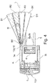
- FIGS. 1 to 4 in each case an inventive truck 1 is shown in a plan view.
- the truck 1 is designed as a reach truck 2 in the illustrated embodiments.
- the same components are provided in the figures with the same reference numerals.
- the reach truck 2 has a vehicle body 3, which has two mutually parallel wheel arms 3a, 3b, which extend in the vehicle longitudinal direction. Between the wheel arms 3a, 3b designed as a mast lifting mast 4 is arranged displaceably in the vehicle longitudinal direction. On the mast 4, a load-receiving means 5 is arranged raised and lowered, which is designed for example as a fork with two forks 6a, 6b.
- a roller is arranged, with which the truck 1 is supported on a roadway.
- a sensor device 10a, 10b for monitoring an environmental region is provided on the wheel arms 3a, 3b.
- a warning signal is generated and / or an intervention in the travel drive of the industrial truck 1 is carried out,
- the truck braked to avoid collision with the obstacle For example, the truck braked to avoid collision with the obstacle.
- the sensor devices 10a, 10b have corresponding detection areas D1, D2, which form the monitoring areas which are monitored for obstacles. If an obstacle is detected in the detection area D1, D2, a warning signal is generated and / or an intervention in the traction drive of the industrial truck 1 is carried out.
- the detection area D1, D2 are aligned with the area in front of the wheel arms 3a, 3b or in front of the load-receiving means 5 when the truck 1 travels ahead in the direction of travel with the load-receiving means 5.
- the sensor device 10a, 10b in the FIGS. 1 to 4 arranged such or arranged on the truck 1 that an obstacle H, for example, a shelf support of a shelf or parked pallet, which is located outside a line L, which is aligned with the vehicle outer contour K of the truck 1 and the vehicle outer contour (vehicle outer edge) K in Extended direction of travel of the truck 1, outside the detection range D1 or D2 of the sensor device 10a, 10b is located, in which generates a warning signal and / or an intervention in the traction drive of the truck is performed.
- an obstacle H for example, a shelf support of a shelf or parked pallet, which is located outside a line L, which is aligned with the vehicle outer contour K of the truck 1 and the vehicle outer contour (vehicle outer edge) K in Extended direction of travel of the truck 1, outside the detection range D1 or D2 of the sensor device 10a, 10b is located, in which generates a warning signal and / or an intervention in the traction drive of the truck is performed.
- the sensor device 10a, 10b is for this purpose in the FIGS. 1 to 4 arranged such or arranged on the truck 1, that the detection range D1, D2 of the sensor device 10a, 10b with an outer boundary edge B on or within the line L, which is aligned with the vehicle outer contour K of the truck 1 and the vehicle outer contour K in the direction of travel of the truck 1 extended.
- the outer boundary edge B of the detection area D1, D2 is arranged in a line with the vehicle outer contour K of the truck 1 or its extension in the direction of travel.
- the sensor devices 10a, 10b each have a single detection area D1, D2.
- the sensor devices 10a, 10b are configured as an ultrasonic sensor 11 or as a radar sensor 12 or as an inductive sensor.
- the sensor devices 10a, 10b are designed as a single-beam laser sensor 13.
- the sensor devices 10a, 10b are adjustably arranged on the industrial truck 1 by means of an adapter, not shown, in order to achieve the inventive alignment of the detection areas D1, D2 by appropriate arrangement and alignment of the sensor devices 10a, 10b, according to which the outer boundary edge B of the respective single Detection range D1, D2 in a line with the vehicle outer contour K of the truck 1 or its extension in the direction of travel.
- FIG. 2 is arranged on the Radarm 3b designed as an ultrasonic sensor 12 sensor device 10b, wherein the detection area D2 is formed in the form of a sound lobe.
- the detection area D2 is configured as an ultrasonic sensor 12 sensor device 10b, for example by means of an adapter not shown arranged on the truck 1 to achieve by appropriate arrangement and orientation of the ultrasonic sensor 12, the inventive alignment of the detection area D2, according to which the sound beam is parallel to the line L, which extends the vehicle outer contour K in the direction of travel and thus the outer boundary edge B of the detection area D1, D2 is in line with the vehicle outer contour K of the truck 1 and its extension in the direction of travel.
- the one-beam laser sensor 13 arranged on the wheel arm 3a is arranged on the industrial truck 1 in such a way that the laser beam forming the outer boundary edge B of the detection area D1 is aligned along the vehicle outer contour K and its extension in the direction of travel.
- the emitted laser beam is thus on the line L, which is aligned with the vehicle outer contour K and extends it in the direction of travel.
- the one-beam laser sensor 13 is arranged on the vehicle outer contour K for this purpose.
- a deflection mirror 15 is provided which deflects the emitted laser beam such that the outer boundary edge B of the detection area D1 forming laser beam along the vehicle outer contour K and their extension is aligned in the direction of travel, so that emitted laser beam is on the line L, which is aligned with the vehicle outer contour K and extends it in the direction of travel.
- the single-beam laser sensor 13 on the truck 1 further inside and thus be protected.
- FIG. 4 an industrial truck 1 is shown in which a sensor device 10a is arranged on the wheel arm 3a, which can monitor a plurality of regions B1-B5 in the detection area D1.
- the sensor device 10a of FIG. 4 is designed for example as a lidar sensor or time-of-flight camera 16 or stereo camera. Such sensor devices deliver a plurality of pixels in the detection region D1, so that a plurality of regions B1-B5 within the detection region D1 can be distinguished.
- This sensor device 10a is designed such that only those areas B3, B4, B5 are evaluated by the sensor device 10a for monitoring an obstacle, which are located within the vehicle contour K or its extension in the direction of travel (line L).
- the areas B1, B2 of the detection area D1 which protrude beyond a certain distance from the vehicle contour K or its extension in the direction of travel, are software-technologically considered only up to this distance for monitoring.
- the outgoing from the vehicle outer contour K or its extension in the direction of travel and thus beyond the line L areas B1, B2 can be switched off and thus excluded from the monitoring.
- a warning signal and / or an intervention in the traction drive of the truck 1 only takes place if an obstacle is detected in the areas B3, B4, B5 which form the monitored detection area D1.
- the shutdown of the protruding from the vehicle outer contour K areas B1, B2 can also be done in dependence on the steering angle of the truck 1, so that cornering of the truck can be considered.
- the inventive arrangement of the sensor device 10, 10b in the FIGS. 1 to 3 or the inventive design of the sensor device 10a of FIG. 4 be achieved, that if the truck 1 passes the obstacle H with a small lateral distance, the obstacle H is not in the detection range D1 or D2 of the sensor device 10a, 10b, in which generates a warning signal and / or a Intervention in the traction drive of the truck 1 is performed.
- the obstacle H is not recognized by the sensor device 10a, 10b and no warning signal is generated and / or no intervention in the traction drive of the industrial truck 1 is carried out.
- misdetections can be avoided when driving near the truck 1 on an obstacle H.
- an industrial truck 1 which is operated by a driver and an assistance system is provided which generates a warning signal at an obstacle detected in the detection area D1, D2 of the sensor device 10a, 10b and / or performs an intervention in the traction drive of the industrial truck 1, can According to the invention, when a warning signal is not generated on a barrier H when passing by near-by and / or no intervention is made in the travel drive of the industrial truck 1, the acceptance by the driver is increased.
- the invention is not limited to the illustrated embodiment of a truck 1 as a reach truck, but can also be used in other embodiments of industrial trucks 1, for example in a counterbalance forklift.
- the invention can also be used not only for one direction of travel with the load-receiving means 5 ahead, but also for the opposite or both directions of the truck. 1
- a deflection mirror 15 of the FIG. 3 can also be a signal of an ultrasonic sensor 11 are deflected and an ultrasonic sensor further inside and thus protected.
Landscapes
- Engineering & Computer Science (AREA)
- Structural Engineering (AREA)
- Automation & Control Theory (AREA)
- Remote Sensing (AREA)
- Physics & Mathematics (AREA)
- General Physics & Mathematics (AREA)
- Radar, Positioning & Navigation (AREA)
- Life Sciences & Earth Sciences (AREA)
- Geology (AREA)
- Mechanical Engineering (AREA)
- Aviation & Aerospace Engineering (AREA)
- Transportation (AREA)
- Civil Engineering (AREA)
- Optical Radar Systems And Details Thereof (AREA)
- Forklifts And Lifting Vehicles (AREA)
Applications Claiming Priority (1)
| Application Number | Priority Date | Filing Date | Title |
|---|---|---|---|
| DE102016120117.0A DE102016120117A1 (de) | 2016-10-21 | 2016-10-21 | Flurförderzeug mit einer Sensoreinrichtung zur Überwachung eines Umgebungsbereiches |
Publications (2)
| Publication Number | Publication Date |
|---|---|
| EP3312131A1 true EP3312131A1 (fr) | 2018-04-25 |
| EP3312131B1 EP3312131B1 (fr) | 2023-07-12 |
Family
ID=59974341
Family Applications (1)
| Application Number | Title | Priority Date | Filing Date |
|---|---|---|---|
| EP17193765.9A Active EP3312131B1 (fr) | 2016-10-21 | 2017-09-28 | Chariot de manutention doté d'un dispositif capteur permettant de surveiller un environnement |
Country Status (2)
| Country | Link |
|---|---|
| EP (1) | EP3312131B1 (fr) |
| DE (1) | DE102016120117A1 (fr) |
Cited By (8)
| Publication number | Priority date | Publication date | Assignee | Title |
|---|---|---|---|---|
| EP3587894A1 (fr) * | 2018-06-28 | 2020-01-01 | Leuze electronic GmbH + Co. KG | Agencement de capteurs et procédé de fonctionnement d'un agencement de capteurs |
| EP3960662A1 (fr) * | 2020-08-25 | 2022-03-02 | Jungheinrich Aktiengesellschaft | Système doté d'un chariot de rayonnage et un rayonnage d'entreposage |
| CN115072316A (zh) * | 2022-08-01 | 2022-09-20 | 安徽行者智能科技股份有限公司 | 一种大尺寸复杂曲面智能加工系统用多功能转运模块 |
| EP4137437A1 (fr) * | 2021-08-17 | 2023-02-22 | Schiller Automatisierungstechnik GmbH | Procédé de fonctionnement d'un moyen de transport |
| WO2023020940A1 (fr) * | 2021-08-17 | 2023-02-23 | Schiller Automatisierungstechnik Gmbh | Procédé de fonctionnement d'un moyen de transport |
| EP4183737A1 (fr) * | 2021-11-19 | 2023-05-24 | Jungheinrich Aktiengesellschaft | Procédé de traitement de perturbations dans des chariots de manutention |
| US11820634B2 (en) | 2020-02-21 | 2023-11-21 | Crown Equipment Corporation | Modify vehicle parameter based on vehicle position information |
| EP4071102B1 (fr) | 2019-12-03 | 2024-08-28 | Kabushiki Kaisha Toyota Jidoshokki | Véhicule industriel |
Families Citing this family (5)
| Publication number | Priority date | Publication date | Assignee | Title |
|---|---|---|---|---|
| DE102018117214A1 (de) * | 2018-07-17 | 2020-01-23 | Jungheinrich Aktiengesellschaft | Schubmaststapler mit einem Überwachungssensor sowie ein Verfahren zum Betrieb eines solchen |
| DE102018128406B4 (de) * | 2018-11-13 | 2023-05-11 | Jungheinrich Aktiengesellschaft | Flurförderzeug mit einem Notstoppsystem |
| DE102019213922A1 (de) * | 2019-09-12 | 2021-03-18 | Jungheinrich Aktiengesellschaft | Fahrzeug mit Umfeldüberwachungseinrichtung |
| DE102020207479A1 (de) | 2020-06-17 | 2021-12-23 | Zf Friedrichshafen Ag | Gabelzinkensensoren zur Erkennung von Querverkehr |
| DE102021103799A1 (de) | 2021-02-18 | 2022-08-18 | Jungheinrich Aktiengesellschaft | Flurförderzeug mit erfassungseinrichtungen an gabelzinken |
Citations (8)
| Publication number | Priority date | Publication date | Assignee | Title |
|---|---|---|---|---|
| JPS5950379A (ja) * | 1982-09-16 | 1984-03-23 | Nippon Denso Co Ltd | 車両用障害物検出装置 |
| GB2157436A (en) * | 1984-04-06 | 1985-10-23 | Bygg Och Transportekonomie Ab | Detecting obstacles in the operation of remote-controlled machines |
| JPS6327398A (ja) * | 1986-07-22 | 1988-02-05 | 株式会社豊田自動織機製作所 | 無人フオ−クリフトの安全装置 |
| US4802096A (en) * | 1987-05-14 | 1989-01-31 | Bell & Howell Company | Controlled direction non-contact detection system for automatic guided vehicles |
| EP0800129B1 (fr) | 1996-04-03 | 2000-07-19 | FIAT OM CARRELLI ELEVATORI S.p.A. | Chariot de manutention utilisable en mode manuel ou automatique |
| DE102008008922A1 (de) | 2008-02-13 | 2009-08-20 | Still Gmbh | Flurförderzeug mit Umgebungssensor |
| EP2339376A1 (fr) * | 2009-12-17 | 2011-06-29 | Sick Ag | Capteur optoélectronique |
| JP2015170284A (ja) * | 2014-03-10 | 2015-09-28 | 株式会社日立製作所 | フォークリフト型無人搬送車、その制御方法および制御装置 |
Family Cites Families (6)
| Publication number | Priority date | Publication date | Assignee | Title |
|---|---|---|---|---|
| US7010404B2 (en) | 2002-01-23 | 2006-03-07 | Kabushiki Kaisha Toyota Jidoshokki | Position control apparatus and position control method for cargo carrying apparatus in industrial vehicle |
| GB0403105D0 (en) | 2004-02-12 | 2004-03-17 | Sim Neil | The safety zone system |
| CA2860745C (fr) | 2006-09-14 | 2016-03-08 | Crown Equipment Corporation | Association d'un emetteur et d'un recepteur dans un systeme de telecommande supplementaire pour des vehicules de manutention de materiaux |
| US20090114485A1 (en) | 2007-11-01 | 2009-05-07 | Eggert Richard T | Lift truck fork aligning system with operator indicators |
| DE102012104808A1 (de) | 2012-06-04 | 2013-12-05 | Still Gmbh | Flurförderzeug mit Positioniervorrichtung |
| EP2722687B1 (fr) | 2012-10-22 | 2015-04-29 | Sick Ag | Dispositif de sécurité pour un véhicule |
-
2016
- 2016-10-21 DE DE102016120117.0A patent/DE102016120117A1/de active Pending
-
2017
- 2017-09-28 EP EP17193765.9A patent/EP3312131B1/fr active Active
Patent Citations (8)
| Publication number | Priority date | Publication date | Assignee | Title |
|---|---|---|---|---|
| JPS5950379A (ja) * | 1982-09-16 | 1984-03-23 | Nippon Denso Co Ltd | 車両用障害物検出装置 |
| GB2157436A (en) * | 1984-04-06 | 1985-10-23 | Bygg Och Transportekonomie Ab | Detecting obstacles in the operation of remote-controlled machines |
| JPS6327398A (ja) * | 1986-07-22 | 1988-02-05 | 株式会社豊田自動織機製作所 | 無人フオ−クリフトの安全装置 |
| US4802096A (en) * | 1987-05-14 | 1989-01-31 | Bell & Howell Company | Controlled direction non-contact detection system for automatic guided vehicles |
| EP0800129B1 (fr) | 1996-04-03 | 2000-07-19 | FIAT OM CARRELLI ELEVATORI S.p.A. | Chariot de manutention utilisable en mode manuel ou automatique |
| DE102008008922A1 (de) | 2008-02-13 | 2009-08-20 | Still Gmbh | Flurförderzeug mit Umgebungssensor |
| EP2339376A1 (fr) * | 2009-12-17 | 2011-06-29 | Sick Ag | Capteur optoélectronique |
| JP2015170284A (ja) * | 2014-03-10 | 2015-09-28 | 株式会社日立製作所 | フォークリフト型無人搬送車、その制御方法および制御装置 |
Cited By (12)
| Publication number | Priority date | Publication date | Assignee | Title |
|---|---|---|---|---|
| EP3587894A1 (fr) * | 2018-06-28 | 2020-01-01 | Leuze electronic GmbH + Co. KG | Agencement de capteurs et procédé de fonctionnement d'un agencement de capteurs |
| EP4071102B1 (fr) | 2019-12-03 | 2024-08-28 | Kabushiki Kaisha Toyota Jidoshokki | Véhicule industriel |
| US11820634B2 (en) | 2020-02-21 | 2023-11-21 | Crown Equipment Corporation | Modify vehicle parameter based on vehicle position information |
| US12116255B2 (en) | 2020-02-21 | 2024-10-15 | Crown Equipment Corporation | Modify vehicle parameter based on vehicle position information |
| US12221330B2 (en) | 2020-02-21 | 2025-02-11 | Crown Equipment Corporation | Lighting floor on sides of material handling vehicle to indicate limited or non-limited area |
| EP3960662A1 (fr) * | 2020-08-25 | 2022-03-02 | Jungheinrich Aktiengesellschaft | Système doté d'un chariot de rayonnage et un rayonnage d'entreposage |
| EP4137437A1 (fr) * | 2021-08-17 | 2023-02-22 | Schiller Automatisierungstechnik GmbH | Procédé de fonctionnement d'un moyen de transport |
| WO2023020940A1 (fr) * | 2021-08-17 | 2023-02-23 | Schiller Automatisierungstechnik Gmbh | Procédé de fonctionnement d'un moyen de transport |
| US12269722B2 (en) | 2021-08-17 | 2025-04-08 | Schiller Automatisierungstechnik Gmbh | Method for operating a means of transport |
| EP4183737A1 (fr) * | 2021-11-19 | 2023-05-24 | Jungheinrich Aktiengesellschaft | Procédé de traitement de perturbations dans des chariots de manutention |
| EP4183737B1 (fr) | 2021-11-19 | 2024-05-01 | Jungheinrich Aktiengesellschaft | Procédé de traitement de perturbations dans des chariots de manutention |
| CN115072316A (zh) * | 2022-08-01 | 2022-09-20 | 安徽行者智能科技股份有限公司 | 一种大尺寸复杂曲面智能加工系统用多功能转运模块 |
Also Published As
| Publication number | Publication date |
|---|---|
| DE102016120117A1 (de) | 2018-04-26 |
| EP3312131B1 (fr) | 2023-07-12 |
Similar Documents
| Publication | Publication Date | Title |
|---|---|---|
| EP3312131A1 (fr) | Chariot de manutention doté d'un dispositif capteur permettant de surveiller un environnement | |
| EP2339376B1 (fr) | Capteur optoélectronique | |
| EP2692688B1 (fr) | Dispositif d'assistance à la conduite pour un chariot de manutention et chariot de manutention | |
| EP2240350B1 (fr) | Utilisation d'un rail guide-roue, installation de lavage de véhicules et procédé de positionnement centré d'un véhicule | |
| EP3241801B1 (fr) | Procédé de surveillance de collision dans un chariot de manutention | |
| EP0800129B1 (fr) | Chariot de manutention utilisable en mode manuel ou automatique | |
| EP4136049B1 (fr) | Chariot de manutention doté de moyens de réception de charge destinés à recevoir des marchandises allongées | |
| EP3132859B1 (fr) | Dispositif de transport disposant d'une detection de collision | |
| DE102012106988B4 (de) | Verfahren zur Steuerung eines Flurförderzeugs | |
| EP3511289B1 (fr) | Procédé de commande d'un chariot de manutention ainsi que système composé d'une unité de commande supérieure et d'un chariot de manutention | |
| EP3800158A1 (fr) | Chariot de manutention, équipé pour un fonctionnement autonome sans conducteur pour une charge à transporter | |
| EP3529194A1 (fr) | Agencement d'un chariot cavalier et d'une rangée d'éléments de repérage espacés | |
| EP4180380A1 (fr) | Procédé de traitement des obstacles dans un chariot de manutention | |
| EP4296215B1 (fr) | Système de transport à déplacement autonome pour le transport de palettes et/ou de boîtes en treillis et procédé de fonctionnement d'un tel système de transport à déplacement autonome | |
| EP4439218A1 (fr) | Véhicule de transport sans conducteur | |
| EP3772483A1 (fr) | Procédé de détermination du mouvement propre d'un chariot de manutention | |
| DE102019215176A1 (de) | Flurförderzeug, eingerichtet für den fahrerlosen, autonom agierenden Betrieb für eine zu transportierende Last | |
| DE10221298A1 (de) | Flurförderzeug mit Abstands-Sensoren | |
| EP4136014B1 (fr) | Système comprenant un train tracteur et au moins une station de transfert fixe | |
| DE3214391A1 (de) | Selbstfahrendes fahrzeug | |
| EP4046958B1 (fr) | Chariot de manutention pourvu de dispositifs de détection sur les dents de fourche | |
| EP4168348B1 (fr) | Capteurs pour bras de fourche pour détecter un trafic transversal | |
| DE102016117589B4 (de) | Flurförderzeug mit einer als Umgebungssensor ausgebildeten Sensoreinrichtung | |
| DE102025104555B3 (de) | Verfahren zum be- und/oder entladen eines laderaums, insbesondere des laderaums eines lastkraftwagens, mit einem autonomen ladefahrzeug und absicherungssystem | |
| EP3984858B1 (fr) | Procédé de détermination des informations sur la propagation d'un support de marchandises dans un chariot de manutention à fonctionnement au moins partiellement automatisé |
Legal Events
| Date | Code | Title | Description |
|---|---|---|---|
| PUAI | Public reference made under article 153(3) epc to a published international application that has entered the european phase |
Free format text: ORIGINAL CODE: 0009012 |
|
| STAA | Information on the status of an ep patent application or granted ep patent |
Free format text: STATUS: THE APPLICATION HAS BEEN PUBLISHED |
|
| AK | Designated contracting states |
Kind code of ref document: A1 Designated state(s): AL AT BE BG CH CY CZ DE DK EE ES FI FR GB GR HR HU IE IS IT LI LT LU LV MC MK MT NL NO PL PT RO RS SE SI SK SM TR |
|
| AX | Request for extension of the european patent |
Extension state: BA ME |
|
| STAA | Information on the status of an ep patent application or granted ep patent |
Free format text: STATUS: REQUEST FOR EXAMINATION WAS MADE |
|
| 17P | Request for examination filed |
Effective date: 20181018 |
|
| RBV | Designated contracting states (corrected) |
Designated state(s): AL AT BE BG CH CY CZ DE DK EE ES FI FR GB GR HR HU IE IS IT LI LT LU LV MC MK MT NL NO PL PT RO RS SE SI SK SM TR |
|
| STAA | Information on the status of an ep patent application or granted ep patent |
Free format text: STATUS: EXAMINATION IS IN PROGRESS |
|
| 17Q | First examination report despatched |
Effective date: 20200902 |
|
| REG | Reference to a national code |
Ref country code: DE Ref legal event code: R079 Free format text: PREVIOUS MAIN CLASS: B66F0017000000 Ipc: B66F0009075000 Ref document number: 502017015035 Country of ref document: DE |
|
| GRAP | Despatch of communication of intention to grant a patent |
Free format text: ORIGINAL CODE: EPIDOSNIGR1 |
|
| STAA | Information on the status of an ep patent application or granted ep patent |
Free format text: STATUS: GRANT OF PATENT IS INTENDED |
|
| RIC1 | Information provided on ipc code assigned before grant |
Ipc: B66F 17/00 20060101ALI20230220BHEP Ipc: B66F 9/075 20060101AFI20230220BHEP |
|
| INTG | Intention to grant announced |
Effective date: 20230329 |
|
| GRAS | Grant fee paid |
Free format text: ORIGINAL CODE: EPIDOSNIGR3 |
|
| GRAA | (expected) grant |
Free format text: ORIGINAL CODE: 0009210 |
|
| STAA | Information on the status of an ep patent application or granted ep patent |
Free format text: STATUS: THE PATENT HAS BEEN GRANTED |
|
| P01 | Opt-out of the competence of the unified patent court (upc) registered |
Effective date: 20230507 |
|
| AK | Designated contracting states |
Kind code of ref document: B1 Designated state(s): AL AT BE BG CH CY CZ DE DK EE ES FI FR GB GR HR HU IE IS IT LI LT LU LV MC MK MT NL NO PL PT RO RS SE SI SK SM TR |
|
| REG | Reference to a national code |
Ref country code: CH Ref legal event code: EP |
|
| REG | Reference to a national code |
Ref country code: DE Ref legal event code: R096 Ref document number: 502017015035 Country of ref document: DE |
|
| REG | Reference to a national code |
Ref country code: IE Ref legal event code: FG4D Free format text: LANGUAGE OF EP DOCUMENT: GERMAN |
|
| REG | Reference to a national code |
Ref country code: SE Ref legal event code: TRGR |
|
| REG | Reference to a national code |
Ref country code: LT Ref legal event code: MG9D |
|
| REG | Reference to a national code |
Ref country code: NL Ref legal event code: MP Effective date: 20230712 |
|
| PG25 | Lapsed in a contracting state [announced via postgrant information from national office to epo] |
Ref country code: NL Free format text: LAPSE BECAUSE OF FAILURE TO SUBMIT A TRANSLATION OF THE DESCRIPTION OR TO PAY THE FEE WITHIN THE PRESCRIBED TIME-LIMIT Effective date: 20230712 |
|
| PG25 | Lapsed in a contracting state [announced via postgrant information from national office to epo] |
Ref country code: GR Free format text: LAPSE BECAUSE OF FAILURE TO SUBMIT A TRANSLATION OF THE DESCRIPTION OR TO PAY THE FEE WITHIN THE PRESCRIBED TIME-LIMIT Effective date: 20231013 |
|
| PG25 | Lapsed in a contracting state [announced via postgrant information from national office to epo] |
Ref country code: ES Free format text: LAPSE BECAUSE OF FAILURE TO SUBMIT A TRANSLATION OF THE DESCRIPTION OR TO PAY THE FEE WITHIN THE PRESCRIBED TIME-LIMIT Effective date: 20230712 |
|
| PG25 | Lapsed in a contracting state [announced via postgrant information from national office to epo] |
Ref country code: IS Free format text: LAPSE BECAUSE OF FAILURE TO SUBMIT A TRANSLATION OF THE DESCRIPTION OR TO PAY THE FEE WITHIN THE PRESCRIBED TIME-LIMIT Effective date: 20231112 |
|
| PG25 | Lapsed in a contracting state [announced via postgrant information from national office to epo] |
Ref country code: RS Free format text: LAPSE BECAUSE OF FAILURE TO SUBMIT A TRANSLATION OF THE DESCRIPTION OR TO PAY THE FEE WITHIN THE PRESCRIBED TIME-LIMIT Effective date: 20230712 Ref country code: PT Free format text: LAPSE BECAUSE OF FAILURE TO SUBMIT A TRANSLATION OF THE DESCRIPTION OR TO PAY THE FEE WITHIN THE PRESCRIBED TIME-LIMIT Effective date: 20231113 Ref country code: NO Free format text: LAPSE BECAUSE OF FAILURE TO SUBMIT A TRANSLATION OF THE DESCRIPTION OR TO PAY THE FEE WITHIN THE PRESCRIBED TIME-LIMIT Effective date: 20231012 Ref country code: LV Free format text: LAPSE BECAUSE OF FAILURE TO SUBMIT A TRANSLATION OF THE DESCRIPTION OR TO PAY THE FEE WITHIN THE PRESCRIBED TIME-LIMIT Effective date: 20230712 Ref country code: LT Free format text: LAPSE BECAUSE OF FAILURE TO SUBMIT A TRANSLATION OF THE DESCRIPTION OR TO PAY THE FEE WITHIN THE PRESCRIBED TIME-LIMIT Effective date: 20230712 Ref country code: IS Free format text: LAPSE BECAUSE OF FAILURE TO SUBMIT A TRANSLATION OF THE DESCRIPTION OR TO PAY THE FEE WITHIN THE PRESCRIBED TIME-LIMIT Effective date: 20231112 Ref country code: HR Free format text: LAPSE BECAUSE OF FAILURE TO SUBMIT A TRANSLATION OF THE DESCRIPTION OR TO PAY THE FEE WITHIN THE PRESCRIBED TIME-LIMIT Effective date: 20230712 Ref country code: GR Free format text: LAPSE BECAUSE OF FAILURE TO SUBMIT A TRANSLATION OF THE DESCRIPTION OR TO PAY THE FEE WITHIN THE PRESCRIBED TIME-LIMIT Effective date: 20231013 Ref country code: FI Free format text: LAPSE BECAUSE OF FAILURE TO SUBMIT A TRANSLATION OF THE DESCRIPTION OR TO PAY THE FEE WITHIN THE PRESCRIBED TIME-LIMIT Effective date: 20230712 Ref country code: ES Free format text: LAPSE BECAUSE OF FAILURE TO SUBMIT A TRANSLATION OF THE DESCRIPTION OR TO PAY THE FEE WITHIN THE PRESCRIBED TIME-LIMIT Effective date: 20230712 |
|
| PG25 | Lapsed in a contracting state [announced via postgrant information from national office to epo] |
Ref country code: PL Free format text: LAPSE BECAUSE OF FAILURE TO SUBMIT A TRANSLATION OF THE DESCRIPTION OR TO PAY THE FEE WITHIN THE PRESCRIBED TIME-LIMIT Effective date: 20230712 |
|
| REG | Reference to a national code |
Ref country code: DE Ref legal event code: R026 Ref document number: 502017015035 Country of ref document: DE |
|
| PLBI | Opposition filed |
Free format text: ORIGINAL CODE: 0009260 |
|
| PLAX | Notice of opposition and request to file observation + time limit sent |
Free format text: ORIGINAL CODE: EPIDOSNOBS2 |
|
| PLAB | Opposition data, opponent's data or that of the opponent's representative modified |
Free format text: ORIGINAL CODE: 0009299OPPO |
|
| PG25 | Lapsed in a contracting state [announced via postgrant information from national office to epo] |
Ref country code: SM Free format text: LAPSE BECAUSE OF FAILURE TO SUBMIT A TRANSLATION OF THE DESCRIPTION OR TO PAY THE FEE WITHIN THE PRESCRIBED TIME-LIMIT Effective date: 20230712 Ref country code: RO Free format text: LAPSE BECAUSE OF FAILURE TO SUBMIT A TRANSLATION OF THE DESCRIPTION OR TO PAY THE FEE WITHIN THE PRESCRIBED TIME-LIMIT Effective date: 20230712 Ref country code: EE Free format text: LAPSE BECAUSE OF FAILURE TO SUBMIT A TRANSLATION OF THE DESCRIPTION OR TO PAY THE FEE WITHIN THE PRESCRIBED TIME-LIMIT Effective date: 20230712 Ref country code: DK Free format text: LAPSE BECAUSE OF FAILURE TO SUBMIT A TRANSLATION OF THE DESCRIPTION OR TO PAY THE FEE WITHIN THE PRESCRIBED TIME-LIMIT Effective date: 20230712 Ref country code: CZ Free format text: LAPSE BECAUSE OF FAILURE TO SUBMIT A TRANSLATION OF THE DESCRIPTION OR TO PAY THE FEE WITHIN THE PRESCRIBED TIME-LIMIT Effective date: 20230712 Ref country code: SK Free format text: LAPSE BECAUSE OF FAILURE TO SUBMIT A TRANSLATION OF THE DESCRIPTION OR TO PAY THE FEE WITHIN THE PRESCRIBED TIME-LIMIT Effective date: 20230712 |
|
| REG | Reference to a national code |
Ref country code: CH Ref legal event code: PL |
|
| PG25 | Lapsed in a contracting state [announced via postgrant information from national office to epo] |
Ref country code: LU Free format text: LAPSE BECAUSE OF NON-PAYMENT OF DUE FEES Effective date: 20230928 |
|
| 26 | Opposition filed |
Opponent name: TOYOTA MATERIAL HANDLING MANUFACTURING SWEDEN AB Effective date: 20240412 |
|
| REG | Reference to a national code |
Ref country code: BE Ref legal event code: MM Effective date: 20230930 |
|
| R26 | Opposition filed (corrected) |
Opponent name: TOYOTA MATERIAL HANDLING MANUFACTURING SWEDEN AB Effective date: 20240412 |
|
| PG25 | Lapsed in a contracting state [announced via postgrant information from national office to epo] |
Ref country code: LU Free format text: LAPSE BECAUSE OF NON-PAYMENT OF DUE FEES Effective date: 20230928 Ref country code: IT Free format text: LAPSE BECAUSE OF FAILURE TO SUBMIT A TRANSLATION OF THE DESCRIPTION OR TO PAY THE FEE WITHIN THE PRESCRIBED TIME-LIMIT Effective date: 20230712 Ref country code: MC Free format text: LAPSE BECAUSE OF FAILURE TO SUBMIT A TRANSLATION OF THE DESCRIPTION OR TO PAY THE FEE WITHIN THE PRESCRIBED TIME-LIMIT Effective date: 20230712 |
|
| PLAB | Opposition data, opponent's data or that of the opponent's representative modified |
Free format text: ORIGINAL CODE: 0009299OPPO |
|
| REG | Reference to a national code |
Ref country code: IE Ref legal event code: MM4A |
|
| PG25 | Lapsed in a contracting state [announced via postgrant information from national office to epo] |
Ref country code: IE Free format text: LAPSE BECAUSE OF NON-PAYMENT OF DUE FEES Effective date: 20230928 |
|
| R26 | Opposition filed (corrected) |
Opponent name: TOYOTA MATERIAL HANDLING MANUFACTURING SWEDEN AB Effective date: 20240412 |
|
| PG25 | Lapsed in a contracting state [announced via postgrant information from national office to epo] |
Ref country code: CH Free format text: LAPSE BECAUSE OF NON-PAYMENT OF DUE FEES Effective date: 20230930 |
|
| PG25 | Lapsed in a contracting state [announced via postgrant information from national office to epo] |
Ref country code: IE Free format text: LAPSE BECAUSE OF NON-PAYMENT OF DUE FEES Effective date: 20230928 Ref country code: CH Free format text: LAPSE BECAUSE OF NON-PAYMENT OF DUE FEES Effective date: 20230930 Ref country code: SI Free format text: LAPSE BECAUSE OF FAILURE TO SUBMIT A TRANSLATION OF THE DESCRIPTION OR TO PAY THE FEE WITHIN THE PRESCRIBED TIME-LIMIT Effective date: 20230712 |
|
| PLBB | Reply of patent proprietor to notice(s) of opposition received |
Free format text: ORIGINAL CODE: EPIDOSNOBS3 |
|
| PG25 | Lapsed in a contracting state [announced via postgrant information from national office to epo] |
Ref country code: BE Free format text: LAPSE BECAUSE OF NON-PAYMENT OF DUE FEES Effective date: 20230930 |
|
| PG25 | Lapsed in a contracting state [announced via postgrant information from national office to epo] |
Ref country code: BG Free format text: LAPSE BECAUSE OF FAILURE TO SUBMIT A TRANSLATION OF THE DESCRIPTION OR TO PAY THE FEE WITHIN THE PRESCRIBED TIME-LIMIT Effective date: 20230712 |
|
| REG | Reference to a national code |
Ref country code: AT Ref legal event code: MM01 Ref document number: 1586954 Country of ref document: AT Kind code of ref document: T Effective date: 20230928 |
|
| PG25 | Lapsed in a contracting state [announced via postgrant information from national office to epo] |
Ref country code: BG Free format text: LAPSE BECAUSE OF FAILURE TO SUBMIT A TRANSLATION OF THE DESCRIPTION OR TO PAY THE FEE WITHIN THE PRESCRIBED TIME-LIMIT Effective date: 20230712 |
|
| PG25 | Lapsed in a contracting state [announced via postgrant information from national office to epo] |
Ref country code: AT Free format text: LAPSE BECAUSE OF NON-PAYMENT OF DUE FEES Effective date: 20230928 |
|
| PG25 | Lapsed in a contracting state [announced via postgrant information from national office to epo] |
Ref country code: AT Free format text: LAPSE BECAUSE OF NON-PAYMENT OF DUE FEES Effective date: 20230928 |
|
| PG25 | Lapsed in a contracting state [announced via postgrant information from national office to epo] |
Ref country code: CY Free format text: LAPSE BECAUSE OF FAILURE TO SUBMIT A TRANSLATION OF THE DESCRIPTION OR TO PAY THE FEE WITHIN THE PRESCRIBED TIME-LIMIT; INVALID AB INITIO Effective date: 20170928 |
|
| PG25 | Lapsed in a contracting state [announced via postgrant information from national office to epo] |
Ref country code: HU Free format text: LAPSE BECAUSE OF FAILURE TO SUBMIT A TRANSLATION OF THE DESCRIPTION OR TO PAY THE FEE WITHIN THE PRESCRIBED TIME-LIMIT; INVALID AB INITIO Effective date: 20170928 |
|
| PGFP | Annual fee paid to national office [announced via postgrant information from national office to epo] |
Ref country code: DE Payment date: 20250919 Year of fee payment: 9 |
|
| PGFP | Annual fee paid to national office [announced via postgrant information from national office to epo] |
Ref country code: GB Payment date: 20250923 Year of fee payment: 9 |
|
| PGFP | Annual fee paid to national office [announced via postgrant information from national office to epo] |
Ref country code: FR Payment date: 20250924 Year of fee payment: 9 |
|
| PGFP | Annual fee paid to national office [announced via postgrant information from national office to epo] |
Ref country code: SE Payment date: 20250922 Year of fee payment: 9 |
|
| PG25 | Lapsed in a contracting state [announced via postgrant information from national office to epo] |
Ref country code: TR Free format text: LAPSE BECAUSE OF FAILURE TO SUBMIT A TRANSLATION OF THE DESCRIPTION OR TO PAY THE FEE WITHIN THE PRESCRIBED TIME-LIMIT Effective date: 20230712 |