EP4137437A1 - Procédé de fonctionnement d'un moyen de transport - Google Patents
Procédé de fonctionnement d'un moyen de transport Download PDFInfo
- Publication number
- EP4137437A1 EP4137437A1 EP21207741.6A EP21207741A EP4137437A1 EP 4137437 A1 EP4137437 A1 EP 4137437A1 EP 21207741 A EP21207741 A EP 21207741A EP 4137437 A1 EP4137437 A1 EP 4137437A1
- Authority
- EP
- European Patent Office
- Prior art keywords
- distance measuring
- measuring device
- conveyor
- area
- segments
- Prior art date
- Legal status (The legal status is an assumption and is not a legal conclusion. Google has not performed a legal analysis and makes no representation as to the accuracy of the status listed.)
- Granted
Links
Images


Classifications
-
- B—PERFORMING OPERATIONS; TRANSPORTING
- B66—HOISTING; LIFTING; HAULING
- B66F—HOISTING, LIFTING, HAULING OR PUSHING, NOT OTHERWISE PROVIDED FOR, e.g. DEVICES WHICH APPLY A LIFTING OR PUSHING FORCE DIRECTLY TO THE SURFACE OF A LOAD
- B66F9/00—Devices for lifting or lowering bulky or heavy goods for loading or unloading purposes
- B66F9/06—Devices for lifting or lowering bulky or heavy goods for loading or unloading purposes movable, with their loads, on wheels or the like, e.g. fork-lift trucks
- B66F9/075—Constructional features or details
- B66F9/0755—Position control; Position detectors
-
- B—PERFORMING OPERATIONS; TRANSPORTING
- B66—HOISTING; LIFTING; HAULING
- B66F—HOISTING, LIFTING, HAULING OR PUSHING, NOT OTHERWISE PROVIDED FOR, e.g. DEVICES WHICH APPLY A LIFTING OR PUSHING FORCE DIRECTLY TO THE SURFACE OF A LOAD
- B66F17/00—Safety devices, e.g. for limiting or indicating lifting force
- B66F17/003—Safety devices, e.g. for limiting or indicating lifting force for fork-lift trucks
-
- B—PERFORMING OPERATIONS; TRANSPORTING
- B66—HOISTING; LIFTING; HAULING
- B66F—HOISTING, LIFTING, HAULING OR PUSHING, NOT OTHERWISE PROVIDED FOR, e.g. DEVICES WHICH APPLY A LIFTING OR PUSHING FORCE DIRECTLY TO THE SURFACE OF A LOAD
- B66F9/00—Devices for lifting or lowering bulky or heavy goods for loading or unloading purposes
- B66F9/06—Devices for lifting or lowering bulky or heavy goods for loading or unloading purposes movable, with their loads, on wheels or the like, e.g. fork-lift trucks
- B66F9/063—Automatically guided
Definitions
- the present invention relates to a method for operating a conveyor equipped with a transport device.
- the conveying means can be, for example, an industrial truck that is used in a goods logistics facility.
- the conveyor can place the goods, i.e. different objects, on the shelves or fetch them from them.
- the conveyor is equipped with a transport device in which the respective object is arranged during transport from/to a shelf.
- this can be the lifting frame with fork carrier and fork tines, which is intended to illustrate a preferred field of application, but is not initially intended to restrict the subject in its generality.
- the present invention is based on the technical problem of specifying an advantageous method for operating a conveyor with a transport device.
- a determination or adaptation of a safety zone of the conveyor depending on a non-contact measurement of the object In the case of a large object that overhangs the conveyor, for example, its safety zone can be enlarged so that predefined minimum distances are maintained despite the overhang.
- a lateral minimum distance taken perpendicular to the main direction of travel is d min
- a larger distance d a >d min is set.
- the safety zone which is taken as a basis for partially autonomous driver support or, in particular, fully autonomous driving, is then correspondingly larger.
- the non-contact measurement is carried out with a distance measuring device, with a segmented scan area being recorded in a preferred embodiment.
- the special feature is not the subdivision into segments per se, but rather the "free or occupied" evaluation of the status in the respective segment.
- the segmentation can be significantly coarser than the resolution of the distance measuring device; a respective segment can therefore, for example, comprise a plurality of pixels or voxels. If the object reaches into the respective segment, regardless of whether it fills it up completely or only partially, the status "occupied" is then determined for this segment.
- a respective segment is classified as "free” if the object does not reach into it.
- occupied segments and e.g. B. result in free segments in edge areas.
- an overhang is then determined which an occupied segment has in relation to the conveyor, and this overhang is added to an original safety zone, ie to the minimum distance d min mentioned.
- the overhangs of all occupied segments can be determined and the maximum value can then be used as a basis, but it is also possible, for example, to sort out segments located further inwards in advance and the respective overhang can only be determined for the outer or outermost occupied segments.
- the approach is not to image the object with the distance measurement, but to capture it via the segments in a comparatively coarser grid.
- a certain degree of granularity is therefore accepted, which, however, conversely increases the security in the allocation "free” or "occupied".
- the remaining pixels/voxels for the segment as a whole could still ensure “occupied” detection.
- a little more overhang is therefore opened up, for example if the object only fills an “inner” area, ie one that is close to the conveying means, of the segment then used as a basis for determining the safety zone.
- this level of granularity can increase security compared to a contour-accurate depiction of the object, which could be used to avoid this.
- a "scan area” is not intended to exclude an overall three-dimensional scan area; the distance measuring device can therefore also have a resolution angled or perpendicular to the scanning surface.
- the overall view it can e.g. B. give several offset scan areas, which can, for example, in a matrix-like breakdown each correspond to a line.
- the distance measuring device is preferably set up for a time-of-flight-based distance measurement using electromagnetic pulses.
- the distance measuring device can preferably be a laser scanner, the laser pulses of which are emitted sequentially in different spatial directions, i.e.
- beams are geometric elements and specify the lines along which the pulses are emitted.
- This emission along the mutually tilted beams can be achieved, for example, by guiding the pulses via an oscillating or rotating reflector of the distance measuring device.
- the distance measuring device spans the scanning area with its solid angle resolution, i.e. with spatial directions or beams that are tilted relative to one another.
- it can also be designed to be spatial angle-sensitive, i.e. echo pulses coming from different spatial directions can be assigned to the different spatial directions in a receiving unit of the distance measuring device (e.g. via an optical system that guides echo pulses coming from different spatial directions to different areas of a sensor surface).
- solid-angle-selective emission is preferred, for example via a corresponding reflector.
- the scanning area is located in such a way that it intersects the arrangement area, i.e. then accordingly also the object arranged there.
- the "object” is the entire picked up and transported object, so it can, for example, include both the goods themselves and a storage and/or transport means, such as a container or, in particular, a pallet.
- the scanning area can generally also be vertical, so, for example, with a view to underpasses, etc., height overhangs can be determined.
- the scanning surface is preferably at least partially horizontal, ie a lateral overhang is determined; it is particularly preferably parallel to the horizontal directions of the stationary coordinate system.
- the scanning area is significantly smaller than the range of the distance measuring device, which means that it is oversized in a certain way.
- the range is considered at the highest angular resolution of the distance measuring device, i.e. at the smallest angular distance between the beams.
- the range can then result, for example, from the scanning frequency (e.g. the frequency of the rotating or oscillating reflector), i.e. ultimately from the length of time for which an echo pulse from a specific spatial direction is awaited before a subsequent pulse is emitted in a different spatial direction.
- the maximum range can increase security, e.g. the detection probability of weakly reflective surface areas.
- the extension of the scan area in a particular direction, ie z. B. along a respective beam for example. Make up at most 50% of the range of the distance measuring device taken in this direction (along this beam).
- Further upper limits can be 40% or 30%, for example. Lower limits result less from technical than from economic considerations, values of at least 1%, 2%, 3%, 4% or 5% are mentioned as examples.
- the scan area is considered as a whole, i.e. the totality of all segments evaluated with the "free or occupied" criterion.
- the scan surface is relatively small, namely its average extent is at most 3 m, further and particularly preferably at most 2.5 m or 2 m (along a respective ray) and consider an average of the extents taken along all the rays.
- Possible lower limits of the mean extent can be at least 0.5 m or 1 m, for example.
- the scan area is subdivided into a maximum of 512 segments; further advantageous upper limits are, in the order in which they are named, increasingly preferably a maximum of 512, 256, 128 or 64 segments.
- the angular resolution of the distance measuring device can, for example, be at least 2x, 4x or 8x (upper limits are again more of an economic nature, they can be at most 64x or .32-fold).
- the scan area can be divided into a total of at least 4, 8 or 16 segments, for example, so that a certain resolution is achieved despite the desired granularity, i.e. not an arbitrary amount of additional overhang is kept available.
- the segments are sectors of a circle whose common center point is on the distance measuring device. Together, the circular sectors fan out or span the scanning area, so they are arranged next to one another in a scanning direction, for example. Adjacent circular sectors can be disjunctive or preferably next to one another with a certain overlap (which generally applies to the segments, also independently of the specific design as circular sectors).
- the circle sectors have at least partially different radii (except for the distance measuring device). So it can differ at least some of the segments in their radii, but z. B. within certain groups also the same radii are present.
- the radii can be smaller in a central area and larger at the edges.
- method step iii) and/or the determination of the “vacant”/“occupied” status can be computer-assisted, ie it can be a computer-implemented method step. In general, this can also be done outsourced, for example in a central control unit of the goods logistics facility or generally also cloud-based; however, a local one is preferred Evaluation, ie in a computer unit assigned to the funding. This can be implemented, for example, as an ASIC or, in particular, as a microcontroller. Insofar as the present disclosure generally refers to the "establishment" of the conveying means for certain processes or a certain method, this means in particular that commands are stored in a computer unit (globally or preferably locally) which carry out the corresponding method steps cause.
- the distance measuring device is a safety laser scanner that is equipped with an integrated computer unit.
- This integrated computer unit is then preferably used to determine the respective status “free” or “occupied” for the respective segments. Since the laser scanner is classified as "safe” overall, the evaluation in its integrated computer unit also satisfies this criterion, so the resulting "free"/"occupied” result matrix is also safe. Because it is based on a certified measurement and evaluation, the overhang determined in this way can also be used as a basis, for example, for a partially or, in particular, fully autonomous drive (whereby, for example, DIN EN ISO 3691-4:2020) on safety distances enough is done. The original safety zone, i.e. the original safety distance, can result from such a standard. The safety laser scanner then supplies the "safe" overhang, which is added.
- the determination of the safety zone can preferably be done in a safety controller (safety PLC), z. B. is attached directly to an output of the safety laser scanner (and receives the states "free"/"occupied” from there).
- safety preferably means that at least the performance level (PL) d is satisfied (e.g. defined according to EN ISO 13849).
- the safety laser scanner can be of type 3 according to IEC 61496 or category 3 according to EN ISO 13849, for example. Irrespective of these details, at least one further (separate) safety laser scanner can be provided on the conveyor to secure the journey ("travel laser scanner"), which is particularly preferably identical in construction to the safety laser scanner used to determine the overhang is.
- a total of at least two driving laser scanners and (independently) e.g. B. no more than five or four driving laser scanners may be provided.
- the safety laser scanner for determining the safety zone is preferably not used to secure the journey.
- the invention also relates to a conveyor with a transport device, in particular an industrial truck, the transport device of which preferably comprises a lifting device.
- the conveying means is preferably equipped with the distance measuring device.
- the distance measuring device is positioned and oriented in such a way that its scanning area intersects the arrangement area. Due to the integral design of the distance measuring device as part of the conveying means, this can be achieved regardless of its orientation or direction of travel (the arrangement area is always reliably recorded).
- the transport device preferably has a lifting device with which the arrangement area can be brought to different height positions.
- this can be, for example, a height-adjustable platform with a scissor mechanism, but it preferably has a fork carriage with fork tines, the fork carriage being guided on a mast so that it can be adjusted in height.
- the industrial truck can therefore be designed as a forklift, with which the object can be removed from elevated shelves, for example, in particular a fully autonomous forklift.
- the different height positions are at different geodetic heights; the height can be taken in particular as a vertical distance from a floor of the goods logistics facility (on which, for example, the industrial truck drives and moves horizontally in the process).
- the distance measuring device is arranged on the lifting device in a preferred embodiment, so that it can be brought to the different height positions together with the arrangement area. Accordingly, the scanning area intersects the arrangement area in the different height positions, preferably always in the same place. In this way, the object can already be measured, for example, when or before it is removed from a shelf, which can also be advantageous in terms of time, for example.
- the distance measuring device can be arranged, for example, on the fork carriage or in a fixed position relative thereto and can consequently be offset in height simultaneously with the forks.
- the transport device preferably has forks with which z.
- a pallet transport pallet
- the forks can be inserted horizontally between the feet of the pallet and the latter can then be lifted.
- the distance measuring device is positioned in such a way that the scanning area is below the fork arms.
- it can be mounted on the fork carriage, for example, so the laser scanner can be fixed there in a vertical position below the fork tines.
- the scanning surface preferably lies parallel to a plane spanned by the fork prongs, specifically their upper sides (the picked-up object rests on the upper sides, so its contact surface then lies in the plane).
- the scanning surface is preferably at most 8 cm, further and particularly preferably at most 7 cm or 6 cm below the plane spanned by the fork tines. Possible minimum distances are, for example, 1 cm or 2 cm.
- the appropriately positioned scanning area then intersects, for example, the feet of the picked-up pallet, so the size of the pallet and/or its position on the fork arms can be used to determine the overhang.
- It can e.g. B. Pallets of different sizes are used, whereby these are dimensioned depending on the respective goods in such a way that the goods are always smaller or at most the same size as the pallet, so that the horizontal dimension of the pallet is the horizontal dimension of the object (entirety of pallet and goods) determined. If the goods are positioned on pallets without protruding, these pallets can also be easily placed next to each other in one put down shelf.
- the measurement of the pallet feet can, e.g. due to the relatively simple geometry, provide reproducible and reliable overhang data, which reduces the risk of errors.
- the transport device has a stop sensor, which is used to measure whether the object is arranged in the arrangement area.
- the stop sensor can generally also measure, for example, the vertical support of the object, for example the pallet on the fork arm(s).
- the stop sensor preferably measures horizontal contact, for example of the object on the fork carriage. This can of course be combined with a separate measurement in the vertical direction, such as weighing the object (e.g. with a separate weighing device).
- a coupling can be advantageous in that the measurement of the object with the distance measuring device for determining the overhang is only initiated when the stop sensor indicates correct positioning of the object in the arrangement area.
- the non-contact measurement of the object can be enabled or initiated, for example, when the object is in contact with the fork carriage. This can, for example, simplify a correct assignment of the segments purely geometrically during the evaluation (e.g. the assignment "front" and "rear” pallet feet). Furthermore, for example, the risk of the object slipping later can also be reduced.
- the conveying means is set up to carry out a method disclosed here, ie to adapt the safety zone, preferably also to determine "free"/"occupied” in segments. It is therefore equipped with a corresponding computer unit or units, which can (proportionally) also be part of an integrated safety laser scanner, see details above.
- the invention also relates to a goods logistics facility with shelves that are provided for storing objects, and a conveying means disclosed in the present case, in particular an industrial truck, preferably an autonomous forklift.
- a conveying means disclosed in the present case, in particular an industrial truck, preferably an autonomous forklift.
- This can be, for example, on an area of the goods logistics facility on which z. B. the shelves can also be positioned, move between the latter and a transfer point at which the conveyor / industrial truck accepts goods to be placed on the shelves and / or delivers items fetched from the shelves.
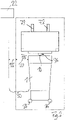
- FIG 1 shows a conveyor 1 for transporting an object 2, which is a product 3 on a pallet 4 in the present case.
- the conveyor 1 is designed as an autonomous forklift truck 5
- a transport device 6 of the conveyor 1 is equipped with a lifting device 7 for lifting the object 2 .
- the lifting device 7 comprises a mast 7.1 on which a fork carriage 7.2 is guided in a vertically displaceable manner.
- the latter carries forks 7.3, the 4.1 for lifting the object 2 between feet Pallet 4 is introduced.
- the fork carriage 7.2 with the forks 7.3 can be placed in different height positions 8 on the mast 7.1.
- the conveyor 1 also has a distance measuring device 10 which is designed as a safety laser scanner 11 in the present case. Its scanning plane 12 is arranged below the fork arms 7.3, namely at a vertical distance 13 of around 6 cm below a plane 14 spanned by the fork arms 7.3 moved up or down together with it.
- the object 3 is placed in an arrangement area 15 of the transport device 7, which in the present case is defined by the fork carrier 7.2 and the fork tines 7.3.
- the correct positioning of the object 3 can be determined via a stop sensor 16.
- figure 2 shows the funding 1 with the object 2 in a plan.
- the conveyor 1 is designed to move autonomously, and an original safety zone 20 is defined around the conveyor 1 .
- This specifies a safety distance which, for example, must not be fallen short of when navigating within a goods logistics facility 21, which is therefore maintained in relation to objects 22 in any case.
- the object 2 has a projection 25 in relation to the conveying means 1, ie the original safety zone 20 would be too small when the object 2 is being transported.
- the safety distances would become too large if the maximum possible dimensions of the goods are always taken as a basis.
- the object 2 is therefore measured without contact using the distance measuring device 10 and a safety zone 30 is determined by adding an overhang 35 to the original safety zone 20 .
- three separate driving laser scanners 36 are provided on the conveyor 1 in this example; also compare the summary with FIG figure 1 .
- FIG 3 illustrates the determination of the overhang 35 in detail
- a scanning surface 40 of the distance measuring device 10 is shown in plan view. This is in several segments 40a-f, wherein for the sake of clarity only one half of the scanning surface 40 is shown segmented in detail, but the other half (on the left in the figure) is subdivided with mirror symmetry in the present example.
- the fork carrier 7.2 is shown, in front of it or in the figure above it, a foot 4.1 of the pallet 4 can be seen.
- a "vacant" status is determined for the segments 40a-c, e, f, while an "occupied” status is determined for the segment 40d.
- the projection 35 is determined for this occupied segment 40d, with its maximum lateral extension being used as a basis.
- the overhang 35 compared to the conveyor 1, specifically its outer edge 45, is therefore somewhat larger than it would be if the foot 4.1 or object 2 were measured exactly, but on the other hand the reliability of this measurement is increased, compare the introduction to the description in detail.
- two further pallet feet are also drawn in dashed lines, namely for a smaller pallet (4.1a) and a larger pallet (4.1b).
- segment 40b, c would be occupied, ie the segment 40c would be used as the basis for determining the overhang.
- segment 40e would be occupied, the remaining segments 40a-d and 40f would be free, and the overhang would be determined using segment 40e.
- the scanning surface 40 lies in the scanning plane 12, the segments 40a-f being dimensioned smaller than a range 47, ie in a respective direction 46 an extension 48 is smaller than the respective maximum possible range 47.
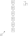
- figure 4 summarizes some method steps in a flowchart 50.
- the object 2 is arranged 51 in the arrangement area 15 of the transport device 7 , the correct positioning being determined by a stop sensor measurement 52 of the stop sensor 16 .
- the object 2 is measured 53 with the distance measuring device 10 and a respective status “free” or “occupied” is determined 54 for the respective segments 40a-f
- a projection 35 is determined 55 in the segment, which is then added 56 to the original safety zone 20 .
Landscapes
- Engineering & Computer Science (AREA)
- Structural Engineering (AREA)
- Transportation (AREA)
- Life Sciences & Earth Sciences (AREA)
- Geology (AREA)
- Mechanical Engineering (AREA)
- Civil Engineering (AREA)
- Length Measuring Devices By Optical Means (AREA)
- Control Of Conveyors (AREA)
- Forklifts And Lifting Vehicles (AREA)
- Intermediate Stations On Conveyors (AREA)
Priority Applications (2)
| Application Number | Priority Date | Filing Date | Title |
|---|---|---|---|
| US18/684,289 US12269722B2 (en) | 2021-08-17 | 2022-08-11 | Method for operating a means of transport |
| PCT/EP2022/072590 WO2023020940A1 (fr) | 2021-08-17 | 2022-08-11 | Procédé de fonctionnement d'un moyen de transport |
Applications Claiming Priority (1)
| Application Number | Priority Date | Filing Date | Title |
|---|---|---|---|
| DE102021004184.4A DE102021004184A1 (de) | 2021-08-17 | 2021-08-17 | Verfahren zum Betreiben eines Fördermittels |
Publications (3)
| Publication Number | Publication Date |
|---|---|
| EP4137437A1 true EP4137437A1 (fr) | 2023-02-22 |
| EP4137437B1 EP4137437B1 (fr) | 2024-03-13 |
| EP4137437C0 EP4137437C0 (fr) | 2024-03-13 |
Family
ID=78598927
Family Applications (1)
| Application Number | Title | Priority Date | Filing Date |
|---|---|---|---|
| EP21207741.6A Active EP4137437B1 (fr) | 2021-08-17 | 2021-11-11 | Procédé de fonctionnement d'un moyen de transport |
Country Status (4)
| Country | Link |
|---|---|
| EP (1) | EP4137437B1 (fr) |
| CA (1) | CA3229505A1 (fr) |
| DE (1) | DE102021004184A1 (fr) |
| ES (1) | ES2977890T3 (fr) |
Cited By (1)
| Publication number | Priority date | Publication date | Assignee | Title |
|---|---|---|---|---|
| DE102023106517A1 (de) * | 2023-03-15 | 2024-09-19 | Hubtex Maschinenbau Gmbh & Co. Kg | Verfahren zum automatischen Steuern eines Flurförderzeugs und Flurförderzeug |
Families Citing this family (2)
| Publication number | Priority date | Publication date | Assignee | Title |
|---|---|---|---|---|
| US12209004B2 (en) * | 2021-10-29 | 2025-01-28 | Mitsubishi Logisnext Co., LTD. | Initial setting method of unmanned forklift, palette for adjustment, and adjustment system of unmanned forklift |
| DE102024122265A1 (de) * | 2024-08-05 | 2026-02-05 | Linde Material Handling Gmbh | Flurförderzeug |
Citations (8)
| Publication number | Priority date | Publication date | Assignee | Title |
|---|---|---|---|---|
| US4266106A (en) * | 1979-04-05 | 1981-05-05 | The Stroh Brewery Co. | Lift truck load position sensing device |
| FR2677006A1 (fr) * | 1991-05-28 | 1992-12-04 | Sodalfa | Dispositif d'assistance pour le deplacement de charges standardisees par un chariot elevateur. |
| DE102004047209A1 (de) * | 2004-09-27 | 2006-03-16 | Daimlerchrysler Ag | Verfahren und Vorrichtung zur Sicherheitsüberwachung für Transportfahrzeuge |
| US20080011554A1 (en) * | 2003-05-26 | 2008-01-17 | Ralf Broesel | Movable sensor device on the loading means of a forklift |
| BE1018160A3 (nl) * | 2008-05-26 | 2010-06-01 | Egemin Nv | Automatisch gestuurd voertuig en werkwijze voor het sturen daarbij toegepast. |
| EP2385014A1 (fr) * | 2010-05-03 | 2011-11-09 | Siemens Aktiengesellschaft | Chariot de manutention doté d'un dispositif destiné à l'identification d'un produit de transport chargé et procédé destiné à l'identification d'un produit de transport chargé d'un chariot de manutention |
| EP3312131A1 (fr) * | 2016-10-21 | 2018-04-25 | Linde Material Handling GmbH | Chariot de manutention doté d'un dispositif capteur permettant de surveiller un environnement |
| US20200031642A1 (en) * | 2017-03-22 | 2020-01-30 | Nec Corporation | Vehicle-mounted device, cargo handling machine, control circuit, control method, and program thereof |
-
2021
- 2021-08-17 DE DE102021004184.4A patent/DE102021004184A1/de active Pending
- 2021-11-11 EP EP21207741.6A patent/EP4137437B1/fr active Active
- 2021-11-11 ES ES21207741T patent/ES2977890T3/es active Active
-
2022
- 2022-08-11 CA CA3229505A patent/CA3229505A1/fr active Pending
Patent Citations (8)
| Publication number | Priority date | Publication date | Assignee | Title |
|---|---|---|---|---|
| US4266106A (en) * | 1979-04-05 | 1981-05-05 | The Stroh Brewery Co. | Lift truck load position sensing device |
| FR2677006A1 (fr) * | 1991-05-28 | 1992-12-04 | Sodalfa | Dispositif d'assistance pour le deplacement de charges standardisees par un chariot elevateur. |
| US20080011554A1 (en) * | 2003-05-26 | 2008-01-17 | Ralf Broesel | Movable sensor device on the loading means of a forklift |
| DE102004047209A1 (de) * | 2004-09-27 | 2006-03-16 | Daimlerchrysler Ag | Verfahren und Vorrichtung zur Sicherheitsüberwachung für Transportfahrzeuge |
| BE1018160A3 (nl) * | 2008-05-26 | 2010-06-01 | Egemin Nv | Automatisch gestuurd voertuig en werkwijze voor het sturen daarbij toegepast. |
| EP2385014A1 (fr) * | 2010-05-03 | 2011-11-09 | Siemens Aktiengesellschaft | Chariot de manutention doté d'un dispositif destiné à l'identification d'un produit de transport chargé et procédé destiné à l'identification d'un produit de transport chargé d'un chariot de manutention |
| EP3312131A1 (fr) * | 2016-10-21 | 2018-04-25 | Linde Material Handling GmbH | Chariot de manutention doté d'un dispositif capteur permettant de surveiller un environnement |
| US20200031642A1 (en) * | 2017-03-22 | 2020-01-30 | Nec Corporation | Vehicle-mounted device, cargo handling machine, control circuit, control method, and program thereof |
Cited By (1)
| Publication number | Priority date | Publication date | Assignee | Title |
|---|---|---|---|---|
| DE102023106517A1 (de) * | 2023-03-15 | 2024-09-19 | Hubtex Maschinenbau Gmbh & Co. Kg | Verfahren zum automatischen Steuern eines Flurförderzeugs und Flurförderzeug |
Also Published As
| Publication number | Publication date |
|---|---|
| CA3229505A1 (fr) | 2023-02-23 |
| EP4137437B1 (fr) | 2024-03-13 |
| ES2977890T3 (es) | 2024-09-02 |
| EP4137437C0 (fr) | 2024-03-13 |
| DE102021004184A1 (de) | 2023-02-23 |
Similar Documents
| Publication | Publication Date | Title |
|---|---|---|
| EP3875990B1 (fr) | Système d'inspection d'un dépôt | |
| WO2023020940A1 (fr) | Procédé de fonctionnement d'un moyen de transport | |
| EP4137437B1 (fr) | Procédé de fonctionnement d'un moyen de transport | |
| DE102006039382A1 (de) | Stückgut-Transportvorrichtung für ein Stückgut-Lagersystem, und Verfahren zum Betreiben der Vorrichtung | |
| EP0656868B1 (fr) | Procede et dispositif de commande d'un pont dechargeur pour conteneurs | |
| WO2004041707A1 (fr) | Grue de transport de conteneurs | |
| DE112017004816T5 (de) | Förderer-screening während des robotergestützten entladens von artikeln | |
| EP2385014B1 (fr) | Chariot de manutention doté d'un dispositif destiné à l'identification d'un produit de transport chargé et procédé destiné à l'identification d'un produit de transport chargé d'un chariot de manutention | |
| DE2944496A1 (de) | Regalfoerderzeug mit abstandstaster | |
| DE112022001463T5 (de) | Transportmöglichkeitsermittlungsvorrichtung, Entfernungsmessvorrichtung, Transporteinheit, Transportmöglichkeitsermittlungsverfahren und Transportmöglichkeitsermittlungsprogramm | |
| DE202019102253U1 (de) | Vorrichtung zum Verifizieren von Lagergut-Positionen in intralogistischen Lagersystemen | |
| EP3529193A1 (fr) | Procédé de positionnement automatique d'un chariot cavalier pour conteneurs et chariot cavalier correspondant | |
| EP3118152A1 (fr) | Procédé de commande de la vitesse d'un chariot de manutention pour la préparation de commandes | |
| EP4439218A1 (fr) | Véhicule de transport sans conducteur | |
| EP4284735A1 (fr) | Procédé pour emmagasiner plusieurs objets de types différents dans un rayonnage de stockage et système de stockage à rayonnages prévu à cet effet | |
| DE19841570C2 (de) | Kaikran zum Be- und Entladen von Containern | |
| EP4482771B1 (fr) | Ensemble et procédé d'insertion d'un conteneur roulant dans un poste de chargement de conteneurs roulants | |
| DE112022000929T5 (de) | Automatisierte einheitslast-abfertigungsverfahren und -systeme | |
| EP3020677A1 (fr) | Procede de preselection de la hauteur de levage pour un chariot de manutention | |
| DE102019202067B4 (de) | Zustandserfassungsvorrichtung, Verfahren zum Erfassen eines Zustands sowie Fahrzeug | |
| DE102024115850A1 (de) | Automatische Regalinspektion in Hochregallagern | |
| DE20004435U1 (de) | Vorrichtung zum lagenweisen Stapeln und Entstapeln von Behältern | |
| DE20220364U1 (de) | Einrichtung zur Positionierung von Transportfahrzeugen für Container im Umschlagbereich eines Containerkrans | |
| EP4440958A1 (fr) | Système de chargement/déchargement de palettes et procédé pour charger/décharger des palettes | |
| DE102013112016B4 (de) | Flurförderzeug mit einem Hubhöhenassistenzsystem |
Legal Events
| Date | Code | Title | Description |
|---|---|---|---|
| PUAI | Public reference made under article 153(3) epc to a published international application that has entered the european phase |
Free format text: ORIGINAL CODE: 0009012 |
|
| STAA | Information on the status of an ep patent application or granted ep patent |
Free format text: STATUS: REQUEST FOR EXAMINATION WAS MADE |
|
| 17P | Request for examination filed |
Effective date: 20221221 |
|
| AK | Designated contracting states |
Kind code of ref document: A1 Designated state(s): AL AT BE BG CH CY CZ DE DK EE ES FI FR GB GR HR HU IE IS IT LI LT LU LV MC MK MT NL NO PL PT RO RS SE SI SK SM TR |
|
| RBV | Designated contracting states (corrected) |
Designated state(s): AL AT BE BG CH CY CZ DE DK EE ES FI FR GB GR HR HU IE IS IT LI LT LU LV MC MK MT NL NO PL PT RO RS SE SI SK SM TR |
|
| GRAP | Despatch of communication of intention to grant a patent |
Free format text: ORIGINAL CODE: EPIDOSNIGR1 |
|
| STAA | Information on the status of an ep patent application or granted ep patent |
Free format text: STATUS: GRANT OF PATENT IS INTENDED |
|
| INTG | Intention to grant announced |
Effective date: 20231108 |
|
| GRAS | Grant fee paid |
Free format text: ORIGINAL CODE: EPIDOSNIGR3 |
|
| GRAA | (expected) grant |
Free format text: ORIGINAL CODE: 0009210 |
|
| STAA | Information on the status of an ep patent application or granted ep patent |
Free format text: STATUS: THE PATENT HAS BEEN GRANTED |
|
| AK | Designated contracting states |
Kind code of ref document: B1 Designated state(s): AL AT BE BG CH CY CZ DE DK EE ES FI FR GB GR HR HU IE IS IT LI LT LU LV MC MK MT NL NO PL PT RO RS SE SI SK SM TR |
|
| REG | Reference to a national code |
Ref country code: GB Ref legal event code: FG4D Free format text: NOT ENGLISH |
|
| REG | Reference to a national code |
Ref country code: CH Ref legal event code: EP |
|
| REG | Reference to a national code |
Ref country code: DE Ref legal event code: R096 Ref document number: 502021002958 Country of ref document: DE |
|
| REG | Reference to a national code |
Ref country code: IE Ref legal event code: FG4D Free format text: LANGUAGE OF EP DOCUMENT: GERMAN |
|
| U01 | Request for unitary effect filed |
Effective date: 20240318 |
|
| U07 | Unitary effect registered |
Designated state(s): AT BE BG DE DK EE FI FR IT LT LU LV MT NL PT SE SI Effective date: 20240322 |
|
| PG25 | Lapsed in a contracting state [announced via postgrant information from national office to epo] |
Ref country code: GR Free format text: LAPSE BECAUSE OF FAILURE TO SUBMIT A TRANSLATION OF THE DESCRIPTION OR TO PAY THE FEE WITHIN THE PRESCRIBED TIME-LIMIT Effective date: 20240614 |
|
| PG25 | Lapsed in a contracting state [announced via postgrant information from national office to epo] |
Ref country code: HR Free format text: LAPSE BECAUSE OF FAILURE TO SUBMIT A TRANSLATION OF THE DESCRIPTION OR TO PAY THE FEE WITHIN THE PRESCRIBED TIME-LIMIT Effective date: 20240313 Ref country code: RS Free format text: LAPSE BECAUSE OF FAILURE TO SUBMIT A TRANSLATION OF THE DESCRIPTION OR TO PAY THE FEE WITHIN THE PRESCRIBED TIME-LIMIT Effective date: 20240613 |
|
| PG25 | Lapsed in a contracting state [announced via postgrant information from national office to epo] |
Ref country code: RS Free format text: LAPSE BECAUSE OF FAILURE TO SUBMIT A TRANSLATION OF THE DESCRIPTION OR TO PAY THE FEE WITHIN THE PRESCRIBED TIME-LIMIT Effective date: 20240613 Ref country code: NO Free format text: LAPSE BECAUSE OF FAILURE TO SUBMIT A TRANSLATION OF THE DESCRIPTION OR TO PAY THE FEE WITHIN THE PRESCRIBED TIME-LIMIT Effective date: 20240613 Ref country code: HR Free format text: LAPSE BECAUSE OF FAILURE TO SUBMIT A TRANSLATION OF THE DESCRIPTION OR TO PAY THE FEE WITHIN THE PRESCRIBED TIME-LIMIT Effective date: 20240313 Ref country code: GR Free format text: LAPSE BECAUSE OF FAILURE TO SUBMIT A TRANSLATION OF THE DESCRIPTION OR TO PAY THE FEE WITHIN THE PRESCRIBED TIME-LIMIT Effective date: 20240614 |
|
| REG | Reference to a national code |
Ref country code: ES Ref legal event code: FG2A Ref document number: 2977890 Country of ref document: ES Kind code of ref document: T3 Effective date: 20240902 |
|
| PG25 | Lapsed in a contracting state [announced via postgrant information from national office to epo] |
Ref country code: IS Free format text: LAPSE BECAUSE OF FAILURE TO SUBMIT A TRANSLATION OF THE DESCRIPTION OR TO PAY THE FEE WITHIN THE PRESCRIBED TIME-LIMIT Effective date: 20240713 |
|
| PG25 | Lapsed in a contracting state [announced via postgrant information from national office to epo] |
Ref country code: SM Free format text: LAPSE BECAUSE OF FAILURE TO SUBMIT A TRANSLATION OF THE DESCRIPTION OR TO PAY THE FEE WITHIN THE PRESCRIBED TIME-LIMIT Effective date: 20240313 |
|
| PG25 | Lapsed in a contracting state [announced via postgrant information from national office to epo] |
Ref country code: CZ Free format text: LAPSE BECAUSE OF FAILURE TO SUBMIT A TRANSLATION OF THE DESCRIPTION OR TO PAY THE FEE WITHIN THE PRESCRIBED TIME-LIMIT Effective date: 20240313 |
|
| PG25 | Lapsed in a contracting state [announced via postgrant information from national office to epo] |
Ref country code: PL Free format text: LAPSE BECAUSE OF FAILURE TO SUBMIT A TRANSLATION OF THE DESCRIPTION OR TO PAY THE FEE WITHIN THE PRESCRIBED TIME-LIMIT Effective date: 20240313 |
|
| PG25 | Lapsed in a contracting state [announced via postgrant information from national office to epo] |
Ref country code: SK Free format text: LAPSE BECAUSE OF FAILURE TO SUBMIT A TRANSLATION OF THE DESCRIPTION OR TO PAY THE FEE WITHIN THE PRESCRIBED TIME-LIMIT Effective date: 20240313 |
|
| PG25 | Lapsed in a contracting state [announced via postgrant information from national office to epo] |
Ref country code: SM Free format text: LAPSE BECAUSE OF FAILURE TO SUBMIT A TRANSLATION OF THE DESCRIPTION OR TO PAY THE FEE WITHIN THE PRESCRIBED TIME-LIMIT Effective date: 20240313 Ref country code: SK Free format text: LAPSE BECAUSE OF FAILURE TO SUBMIT A TRANSLATION OF THE DESCRIPTION OR TO PAY THE FEE WITHIN THE PRESCRIBED TIME-LIMIT Effective date: 20240313 Ref country code: RO Free format text: LAPSE BECAUSE OF FAILURE TO SUBMIT A TRANSLATION OF THE DESCRIPTION OR TO PAY THE FEE WITHIN THE PRESCRIBED TIME-LIMIT Effective date: 20240313 Ref country code: PL Free format text: LAPSE BECAUSE OF FAILURE TO SUBMIT A TRANSLATION OF THE DESCRIPTION OR TO PAY THE FEE WITHIN THE PRESCRIBED TIME-LIMIT Effective date: 20240313 Ref country code: IS Free format text: LAPSE BECAUSE OF FAILURE TO SUBMIT A TRANSLATION OF THE DESCRIPTION OR TO PAY THE FEE WITHIN THE PRESCRIBED TIME-LIMIT Effective date: 20240713 Ref country code: CZ Free format text: LAPSE BECAUSE OF FAILURE TO SUBMIT A TRANSLATION OF THE DESCRIPTION OR TO PAY THE FEE WITHIN THE PRESCRIBED TIME-LIMIT Effective date: 20240313 |
|
| REG | Reference to a national code |
Ref country code: DE Ref legal event code: R097 Ref document number: 502021002958 Country of ref document: DE |
|
| U20 | Renewal fee for the european patent with unitary effect paid |
Year of fee payment: 4 Effective date: 20241125 |
|
| PLBE | No opposition filed within time limit |
Free format text: ORIGINAL CODE: 0009261 |
|
| STAA | Information on the status of an ep patent application or granted ep patent |
Free format text: STATUS: NO OPPOSITION FILED WITHIN TIME LIMIT |
|
| 26N | No opposition filed |
Effective date: 20241216 |
|
| PG25 | Lapsed in a contracting state [announced via postgrant information from national office to epo] |
Ref country code: MC Free format text: LAPSE BECAUSE OF FAILURE TO SUBMIT A TRANSLATION OF THE DESCRIPTION OR TO PAY THE FEE WITHIN THE PRESCRIBED TIME-LIMIT Effective date: 20240313 |
|
| PG25 | Lapsed in a contracting state [announced via postgrant information from national office to epo] |
Ref country code: IE Free format text: LAPSE BECAUSE OF NON-PAYMENT OF DUE FEES Effective date: 20241111 |
|
| REG | Reference to a national code |
Ref country code: CH Ref legal event code: U11 Free format text: ST27 STATUS EVENT CODE: U-0-0-U10-U11 (AS PROVIDED BY THE NATIONAL OFFICE) Effective date: 20251201 |
|
| U20 | Renewal fee for the european patent with unitary effect paid |
Year of fee payment: 5 Effective date: 20251117 |
|
| PGFP | Annual fee paid to national office [announced via postgrant information from national office to epo] |
Ref country code: GB Payment date: 20251120 Year of fee payment: 5 |
|
| PGFP | Annual fee paid to national office [announced via postgrant information from national office to epo] |
Ref country code: CH Payment date: 20251201 Year of fee payment: 5 |
|
| PGFP | Annual fee paid to national office [announced via postgrant information from national office to epo] |
Ref country code: ES Payment date: 20251216 Year of fee payment: 5 |
|
| PG25 | Lapsed in a contracting state [announced via postgrant information from national office to epo] |
Ref country code: HU Free format text: LAPSE BECAUSE OF FAILURE TO SUBMIT A TRANSLATION OF THE DESCRIPTION OR TO PAY THE FEE WITHIN THE PRESCRIBED TIME-LIMIT; INVALID AB INITIO Effective date: 20211111 |
|
| PG25 | Lapsed in a contracting state [announced via postgrant information from national office to epo] |
Ref country code: CY Free format text: LAPSE BECAUSE OF FAILURE TO SUBMIT A TRANSLATION OF THE DESCRIPTION OR TO PAY THE FEE WITHIN THE PRESCRIBED TIME-LIMIT; INVALID AB INITIO Effective date: 20211111 |