EP3312475B1 - Verbundwellgetriebeanordnung - Google Patents
Verbundwellgetriebeanordnung Download PDFInfo
- Publication number
- EP3312475B1 EP3312475B1 EP17186845.8A EP17186845A EP3312475B1 EP 3312475 B1 EP3312475 B1 EP 3312475B1 EP 17186845 A EP17186845 A EP 17186845A EP 3312475 B1 EP3312475 B1 EP 3312475B1
- Authority
- EP
- European Patent Office
- Prior art keywords
- teeth
- disposed
- harmonic drive
- wave generator
- drive assembly
- Prior art date
- Legal status (The legal status is an assumption and is not a legal conclusion. Google has not performed a legal analysis and makes no representation as to the accuracy of the status listed.)
- Active
Links
Images


Classifications
-
- F—MECHANICAL ENGINEERING; LIGHTING; HEATING; WEAPONS; BLASTING
- F16—ENGINEERING ELEMENTS AND UNITS; GENERAL MEASURES FOR PRODUCING AND MAINTAINING EFFECTIVE FUNCTIONING OF MACHINES OR INSTALLATIONS; THERMAL INSULATION IN GENERAL
- F16H—GEARING
- F16H49/00—Other gearings
- F16H49/001—Wave gearings, e.g. harmonic drive transmissions
-
- B—PERFORMING OPERATIONS; TRANSPORTING
- B64—AIRCRAFT; AVIATION; COSMONAUTICS
- B64C—AEROPLANES; HELICOPTERS
- B64C13/00—Control systems or transmitting systems for actuating flying-control surfaces, lift-increasing flaps, air brakes, or spoilers
- B64C13/24—Transmitting means
- B64C13/26—Transmitting means without power amplification or where power amplification is irrelevant
- B64C13/28—Transmitting means without power amplification or where power amplification is irrelevant mechanical
- B64C13/34—Transmitting means without power amplification or where power amplification is irrelevant mechanical using toothed gearing
-
- B—PERFORMING OPERATIONS; TRANSPORTING
- B64—AIRCRAFT; AVIATION; COSMONAUTICS
- B64C—AEROPLANES; HELICOPTERS
- B64C13/00—Control systems or transmitting systems for actuating flying-control surfaces, lift-increasing flaps, air brakes, or spoilers
- B64C13/24—Transmitting means
- B64C13/38—Transmitting means with power amplification
-
- Y—GENERAL TAGGING OF NEW TECHNOLOGICAL DEVELOPMENTS; GENERAL TAGGING OF CROSS-SECTIONAL TECHNOLOGIES SPANNING OVER SEVERAL SECTIONS OF THE IPC; TECHNICAL SUBJECTS COVERED BY FORMER USPC CROSS-REFERENCE ART COLLECTIONS [XRACs] AND DIGESTS
- Y02—TECHNOLOGIES OR APPLICATIONS FOR MITIGATION OR ADAPTATION AGAINST CLIMATE CHANGE
- Y02T—CLIMATE CHANGE MITIGATION TECHNOLOGIES RELATED TO TRANSPORTATION
- Y02T50/00—Aeronautics or air transport
- Y02T50/40—Weight reduction
Definitions
- Compound harmonic drive gears are components of actuators that are able to improve upon certain characteristics of traditional gearing systems.
- Compound harmonic drive gears are small, high power density, high gear ration systems that operate at high velocities. High inertia of the high speed side of the compound harmonic drive gear may negatively affect the responsiveness of the harmonic drive gear.
- a compound harmonic drive assembly comprising: a ring gear assembly including: an output arm defining a first opening disposed about a rotational axis and having a first plurality of teeth, a first ground arm that abuts a first side of the output arm, the first ground arm defining a second opening disposed about the rotational axis and having a second plurality of teeth, and a second ground arm that abuts a second side of the output arm, the second ground arm defining a third opening disposed about the rotational axis and having a third plurality of teeth, a wave generator received within the first opening, the second opening, and the third opening along the rotational axis, the wave generator having a body that extends radially between an exterior surface and an interior surface and that extends axially between a first face and a second face, that defines at least one groove that extends radially from an exterior surface towards an interior surface and is disposed between the first face and the second face; and
- a compound harmonic drive assembly includes a ring gear assembly, a wave generator, a flex spline, and a rolling element.
- the ring gear assembly has a plurality of teeth extending radially inward towards a rotational axis.
- the wave generator is received within the ring gear assembly along the rotational axis.
- the wave generator has a body that extends radially between an exterior surface and an interior surface.
- the wave generator has a body that extends axially between a first face and a second face. The body defines at least one groove that extends radially from the exterior surface towards the interior surface.
- the flex spline is disposed between the ring gear assembly and the wave generator.
- the flex spline includes a plurality of meshing teeth that are configured to engage the plurality of teeth.
- the rolling element is disposed between the wave generator and the flex spline.
- the at least one groove extends about the body and is disposed transverse to the rotational axis.
- the rolling element is engages the exterior surface of the body of the wave generator.
- the rolling element is a roller bearing that extends along an axis that is disposed parallel to the rotational axis.
- the rolling element is a roller bearing that extends along an axis that is disposed transverse to the at least one groove.
- a compound harmonic drive assembly includes a ring gear assembly, a wave generator, and a motor.
- the ring gear assembly includes an output arm, a first ground arm, and a second ground arm.
- the output arm defines a first opening that is disposed about a rotational axis and has a first plurality of teeth.
- the first ground arm that abuts a first side of the output arm.
- the first ground arm defines a second opening that is disposed about the rotational axis and has a second plurality of teeth.
- the second ground arm abuts a second side of the output arm.
- the second ground arm defines a third opening that is disposed about the rotational axis and has a third plurality of teeth.
- the wave generator is received within the first opening, the second opening, and the third opening along the rotational axis.
- the wave generator has a body that extends radially between an exterior surface and an interior surface and that extends axially between a first face and a second face.
- the body defines at least one groove that extends radially from an exterior surface towards an interior surface and is disposed between the first face and the second face.
- the motor is arranged to drivably engage the interior surface of the wave generator.
- the first plurality of teeth are radially offset from the second plurality of teeth and the third plurality of teeth.
- the first plurality of teeth are disposed further from the rotational axis than the second plurality of teeth and the third plurality of teeth.
- a flex spline disposed between the ring gear assembly and the wave generator includes a first portion having a first plurality of meshing teeth configured to meshingly engage the first plurality of teeth, a second portion having a second plurality of meshing teeth configured to meshingly engage the second plurality of teeth, and a third portion having a third plurality of meshing teeth configured to meshingly engage the third plurality of teeth.
- the first portion is disposed between and is radially offset from the second portion and the third portion.
- the at least one groove extends about the body and is disposed transverse to the rotational axis.
- a rolling element disposed between the wave generator and the flex spline.
- the rolling element is a roller bearing that extends along an axis that is disposed transverse to the at least one groove.
- the output arm extends in a first direction and the first ground arm and the second ground arm extend in a second direction that is disposed opposite the first direction.
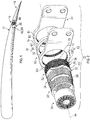
- the flight control system 10 may include a wing or a rotor 12 and a movable control surface 14.
- a compound harmonic drive assembly 20 is operatively coupled to the wing or rotor 12 and the movable control surface 14 to actuate the movable control surface 14.
- the compound harmonic drive assembly 20 may be applied anywhere a high torque, low speed actuator would be desired to move a component or a control surface.
- the compound harmonic drive assembly 20 includes a ring gear assembly 30, a flex spline 32, a rolling element 34, a wave generator 36, and a motor 38.
- the ring gear assembly 30 is disposed about a rotational axis 44.
- the ring gear assembly 30 includes an output arm 50, a first ground arm 52, and a second ground arm 54.
- the output arm 50 extends in a first direction that is substantially perpendicular or transverse to the rotational axis 44.
- the output arm 50 defines a first opening 60 that extends from a first side 62 of the output arm 50 to a second side 64 of the output arm 50.
- the first opening 60 has a first plurality of teeth 66 that extend about the first opening 60 and extend radially inward towards the rotational axis 44.
- the first ground arm 52 extends in a second direction that is disposed opposite the first direction.
- the first ground arm 52 is disposed adjacent to and abuts the first side 62 of the output arm 50.
- the first ground arm 52 defines a second opening 70 that extends completely through the first ground arm 52.
- the second opening 70 is disposed substantially co-linear or coaxially with the first opening 60 along the rotational axis 44.
- the second opening 70 has a second plurality of teeth 72 that extend about the second opening 70 and extend radially inward towards the rotational axis 44.
- the second plurality of teeth 72 are radially offset and axially spaced apart from the first plurality of teeth 66.
- the second ground arm 54 is disposed substantially parallel to the first ground arm 52.
- the second ground arm 54 extends in the second direction that is disposed opposite the first direction.
- the second ground arm 54 is disposed adjacent to and abuts the second side 64 of the output arm 50.
- the second ground arm 54 defines a third opening 80 that extends completely through the second ground arm 54.
- the third opening 80 is disposed substantially co-linear or coaxially with the first opening 60 and the second opening 70 along the rotational axis 44.
- the third opening 80 has a third plurality of teeth 82 that extend about the third opening 80 and extend radially inward towards the rotational axis 44.
- the third plurality of teeth 82 are radially offset and axially spaced apart from the first plurality of teeth 66.
- the flex spline 32 is radially disposed between the ring gear assembly 30 and the rolling element 34.
- the flex spline 32 is axially received within the first opening 60 of the output arm 50, the second opening 70 of the first ground arm 52, and the third opening 80 of the second ground arm 54 of the ring gear assembly 30.
- the flex spline 32 includes a first portion 90, a second portion 92, and a third portion 94.
- the flex spline 32 may be configured as a unitary component or may be configured as distinct segments that are joined together or disposed on top and/or adjacent to each other.
- the first portion 90 is axially disposed between the second portion 92 and the third portion 94.
- the first portion 90 may be radially offset from the second portion 92 and the third portion 94 such that the first portion 90 is disposed further from the rotational axis 44.
- the first portion 90 has a first plurality of meshing teeth 100 that are configured to meshingly engage the first plurality of teeth 66 of the output arm 50 of the ring gear assembly 30.
- the second portion 92 has a second plurality of meshing teeth 102 that are configured to meshingly engage the second plurality of teeth 72 of the first ground arm 52.
- the third portion 194 has a third plurality of meshing teeth 104 that are configured to meshingly the engage the third plurality of teeth 82 of the second ground arm 54.
- the rolling element 34 is radially disposed between the flex spline 32 and the wave generator 36.
- the rolling element 34 is axially received within the flex spline 32.
- the rolling element 34 is configured to engage an interior surface of the first portion 90, the second portion 92, and the third portion 94 of the flex spline 32.
- the rolling element 34 is configured to engage an exterior surface of the wave generator 36.
- the rolling element 34 is a roller bearing that extends along an axis that is disposed parallel to the rotational axis 44.
- the wave generator 36 is disposed about the rotational axis 44.
- the wave generator 36 is radially disposed between the rolling elements 34 and the motor 38.
- the wave generator 36 is axially received within the flex spline 32.
- the rolling element 34 is disposed about the wave generator 36.
- the wave generator 36 is disposed within the first opening 60 of the output arm 50, second opening 70 of the first ground arm 52, and the third opening 80 of the second ground arm 54.
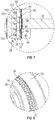
- the wave generator 36 has a body 110 that extends radially between an exterior surface 112 and an interior surface 114.
- the body 110 extends axially between a first face 116 and the second face 118.
- the body 110 of the wave generator 36 includes a land area that is configured as a generally flat region or flat area on the exterior surface 112 of the body 110. The land area extends between the first face 116 and the second face 118.
- the exterior surface 112 has a wave profile having at least two lobes. As shown in FIG. 8 , the wave profile is configured such that during rotation of the wave generator 36 about the rotational axis 44 a lobe of at least two lobes flex the flex spline 32 radially outward such that a localized portion of the first plurality of teeth 66, the second plurality of teeth 72, and the third plurality of teeth 82, respectively, meshingly engage the first plurality of meshing teeth 100, the second plurality of meshing teeth 102, and the third plurality of meshing teeth 104 and another portion of the first plurality of teeth 66, the second plurality of teeth 72 and the third plurality of teeth 82 are, respectively, spaced apart from the first plurality of meshing teeth 100, the second plurality of meshing teeth 102, and the third plurality of meshing teeth 104.
- the body 110 of the wave generator 36 defines at least one groove 120.
- the at least one groove 120 extends from the exterior surface 112 towards the interior surface 114.
- the at least one groove 120 extends about the body 110 and is disposed substantially transverse to the rotational axis 44.
- the at least one groove 120 extends through the land area of the body 110 of the wave generator 36.
- the at least one groove 120 is disposed substantially transverse to the axis along which the rolling element 34 extends. As shown in FIGS. 3 , 6 , and 7 , multiple grooves are provided and are spaced apart from the first face 116 and the second face 118.
- the at least one groove 120 reduces the inertia of the wave generator 36.
- the at least one groove 120 is configured to receive a lubricant or oil such that a larger volume of oil is in contact with the rolling element 34.
- the circulation of the larger volume of oil increases the cooling of the rolling element 34, the wave generator 36, and the flex spline 32.
- the motor 38 is drivably engaged with the wave generator 36.
- the motor 38 is arranged to drivably engage the interior surface 114 of the body 110 of the wave generator 36.
- the motor 38 is configured to spin about the rotational axis 44 to rotate the wave generator 36 to actuate or move the output arm 50 to actuate the movable control surface 14.
- the motor 38 is configured to rotate about the rotational axis 44 in a first direction and in a second direction disposed opposite the first direction.
- the at least one groove 120 formed in the body 110 of the wave generator 36 reduces the weight of the wave generator 36 and thus reduces the inertia the wave generator 36 facilitating a faster response of the compound harmonic drive assembly 20.
- the at least one groove 120 formed in the body 110 of the wave generator 36 enables a faster motor response such that changes in direction and speeds of the wave generator 36 occur more quickly thus improving the response time of the compound harmonic drive assembly 20 and the flight control system 10.
- attachment shall be interpreted to mean that a structural component or element is in some manner connected to or contacts another element, either directly or indirectly through at least one intervening structural element, or is integrally formed with the other structural element.
Landscapes
- Engineering & Computer Science (AREA)
- Mechanical Engineering (AREA)
- General Engineering & Computer Science (AREA)
- Automation & Control Theory (AREA)
- Aviation & Aerospace Engineering (AREA)
- Retarders (AREA)
Claims (8)
- Verbundwellengetriebeanordnung (20), umfassend:eine Zahnkranzanordnung (30), die Folgendes beinhaltet:einen Abtriebsarm (50), der eine erste Öffnung (60) definiert, die um eine Drehachse (44) angeordnet ist, und eine erste Vielzahl von Zähnen (66) aufweist, wobei sich der Abtriebsarm (50) in einer ersten Richtung erstreckt, die im Wesentlichen senkrecht zu der Drehachse ist,einen ersten Bodenarm (52), der an einer ersten Seite (62) des Abtriebsarms angrenzt, wobei der erste Bodenarm eine zweite Öffnung (70) definiert, die um die Drehachse angeordnet ist, und eine zweite Vielzahl von Zähnen (72) aufweist, wobei sich der erste Bodenarm (52) in einer zweiten Richtung erstreckt, die der erste Richtung entgegengesetzt ist, undeinen zweiten Bodenarm (54), der an eine zweite Seite (64) des Abtriebsarms angrenzt, wobei der zweite Bodenarm eine dritte Öffnung (80) definiert, die um die Drehachse angeordnet ist, und eine dritte Vielzahl von Zähnen (82) aufweist, wobei sich der zweite Bodenarm in der zweiten Richtung erstreckt;einen Wellengenerator (36), der in der ersten Öffnung, der zweiten Öffnung und der dritten Öffnung entlang der Drehachse aufgenommen ist, wobei der Wellengenerator einen Körper (110) aufweist, der sich radial zwischen einer äußeren Oberfläche (112) und einer inneren Oberfläche (114) erstreckt und der sich axial zwischen einer ersten Fläche (116) und einer zweiten Fläche (118) erstreckt, der zumindest eine Nut (120) definiert, der sich radial von einer äußeren Oberfläche in Richtung einer inneren Oberfläche erstreckt und zwischen der ersten Fläche und der zweiten Fläche angeordnet ist; undeinen Motor (38), der angeordnet ist, um antreibbar in die innere Oberfläche des Wellengenerators einzugreifen.
- Verbundwellengetriebeanordnung nach Anspruch 1, wobei die erste Vielzahl von Zähnen radial zu der zweiten Vielzahl von Zähnen und der dritten Vielzahl von Zähnen versetzt ist.
- Verbundwellengetriebeanordnung nach Anspruch 2, wobei die erste Vielzahl von Zähnen weiter von der Drehachse entfernt angeordnet ist als die zweite Vielzahl von Zähnen und die dritte Vielzahl von Zähnen.
- Verbundwellengetriebeanordnung nach Anspruch 2, ferner umfassend:
einen Flex-Spline (32), der zwischen der Zahnkranzanordnung und dem Wellengenerator angeordnet ist, wobei der Flex-Spline Folgendes beinhaltet: einen ersten Abschnitt (90), der eine erste Vielzahl von kämmenden Zähnen aufweist, die konfiguriert sind, um kämmend in die erste Vielzahl von Zähnen einzugreifen, einen zweiten Abschnitt (92), der eine zweite Vielzahl von kämmenden Zähnen aufweist, die konfiguriert sind, um kämmend in die zweite Vielzahl von Zähnen einzugreifen, und einen dritten Abschnitt (94), der eine dritte Vielzahl von kämmenden Zähnen aufweist, die konfiguriert sind, um kämmend in die dritte Vielzahl von Zähnen einzugreifen. - Verbundwellengetriebeanordnung nach Anspruch 4, wobei der erste Abschnitt (90) zwischen dem zweiten Abschnitt (92) und dem dritten Abschnitt angeordnet und zu diesen versetzt ist.
- Verbundwellengetriebeanordnung nach Anspruch 4, wobei sich die zumindest eine Nut (120) um den Körper erstreckt und quer zu der Drehachse angeordnet ist.
- Verbundwellengetriebeanordnung nach Anspruch 6, ferner umfassend ein Rollelement (34), das zwischen dem Wellengenerator (36) und dem Flex-Spline (32) angeordnet ist.
- Verbundwellengetriebeanordnung nach Anspruch 7, wobei es sich bei dem Rollelement (34) um ein Rollenlager handelt, das sich entlang einer Achse erstreckt, die quer zu der zumindest einen Nut angeordnet ist.
Applications Claiming Priority (1)
| Application Number | Priority Date | Filing Date | Title |
|---|---|---|---|
| US15/298,656 US10400878B2 (en) | 2016-10-20 | 2016-10-20 | Compound harmonic drive assembly |
Publications (3)
| Publication Number | Publication Date |
|---|---|
| EP3312475A2 EP3312475A2 (de) | 2018-04-25 |
| EP3312475A3 EP3312475A3 (de) | 2018-09-12 |
| EP3312475B1 true EP3312475B1 (de) | 2020-08-05 |
Family
ID=59738146
Family Applications (1)
| Application Number | Title | Priority Date | Filing Date |
|---|---|---|---|
| EP17186845.8A Active EP3312475B1 (de) | 2016-10-20 | 2017-08-18 | Verbundwellgetriebeanordnung |
Country Status (2)
| Country | Link |
|---|---|
| US (1) | US10400878B2 (de) |
| EP (1) | EP3312475B1 (de) |
Families Citing this family (17)
| Publication number | Priority date | Publication date | Assignee | Title |
|---|---|---|---|---|
| US11566690B2 (en) * | 2018-05-21 | 2023-01-31 | Sri International | Variable transmissions with nested pulleys |
| US11085518B2 (en) | 2019-04-18 | 2021-08-10 | Hamilton Sunstrand Corporation | Inverted compound harmonic drive |
| US11519487B2 (en) * | 2019-08-16 | 2022-12-06 | Hamilton Sundstrand Corporation | Compound harmonic gear motor configured for continuous output rotation |
| US11371596B2 (en) * | 2019-09-10 | 2022-06-28 | Hamilton Sundstrand Corporation | Compound harmonic gearbox configured for continuous output rotation |
| US11149834B2 (en) | 2019-11-04 | 2021-10-19 | Hamilton Sundstrand Corporation | Compact compound harmonic drive assembly configured for continuous output rotation |
| WO2021101541A1 (en) * | 2019-11-20 | 2021-05-27 | Sri International | Belt for continuously variable transmission |
| DE102021103936B4 (de) | 2021-02-19 | 2022-12-15 | Liebherr-Aerospace Lindenberg Gmbh | Stellantrieb für eine Steuerfläche eines Luftfahrzeugs |
| EP3998199B1 (de) * | 2021-02-19 | 2023-07-26 | Lilium eAircraft GmbH | Zivilflugzeug ausgestattet mit aktuator für primäre flugsteuerfläche |
| EP4106159B1 (de) | 2021-06-18 | 2025-12-03 | Goodrich Actuation Systems Limited | Überwachung der gesundheit von mehrschichtigen scharnierleitungsaktuatoren |
| US12140213B2 (en) | 2021-08-11 | 2024-11-12 | Hamilton Sundstrand Corporation | Compound harmonic gear system with dual output arms |
| US11713108B2 (en) * | 2021-10-05 | 2023-08-01 | Hamilton Sundstrand Corporation | Hinge-line actuator for rotating an aircraft control surface |
| EP4206490B1 (de) * | 2022-01-03 | 2026-03-18 | Goodrich Actuation Systems SAS | Ein horizontaler stabilisatorantrieb mit einem elektromechanischen linearantrieb |
| US12072009B2 (en) * | 2022-05-27 | 2024-08-27 | Hamilton Sundstrand Corporation | Harmonic gearset with split flexspline |
| EP4386234B1 (de) | 2022-12-16 | 2026-03-11 | Goodrich Actuation Systems Limited | Spannungswellengetriebesystem |
| EP4390178A1 (de) * | 2022-12-23 | 2024-06-26 | Hamilton Sundstrand Corporation | Spannungswellenantrieb |
| US12215769B2 (en) | 2023-02-13 | 2025-02-04 | Hamilton Sundstrand Corporation | Harmonic drive with flex spline end clamps |
| EP4425012A1 (de) * | 2023-03-02 | 2024-09-04 | Goodrich Actuation Systems Limited | Verformungswellgetriebeaktuator, flexpline für einen solchen aktuator und flugzeugsteuerfläche unter verwendung eines solchen aktuators |
Family Cites Families (9)
| Publication number | Priority date | Publication date | Assignee | Title |
|---|---|---|---|---|
| US3172299A (en) * | 1962-06-05 | 1965-03-09 | United Shoe Machinery Corp | Power steering |
| US3555929A (en) * | 1968-08-02 | 1971-01-19 | Usm Corp | Extended root flexsplines |
| DE3277224D1 (en) * | 1982-06-18 | 1987-10-15 | Matsushita Electric Industrial Co Ltd | Reduction gear |
| JP4948479B2 (ja) * | 2008-06-26 | 2012-06-06 | 株式会社ハーモニック・ドライブ・システムズ | 複合型波動歯車減速機 |
| US8516983B2 (en) | 2011-09-30 | 2013-08-27 | Delphi Technologies, Inc. | Harmonic drive camshaft phaser with a harmonic drive ring to prevent ball cage deflection |
| US9145919B2 (en) | 2013-08-14 | 2015-09-29 | Mao-Tu Lee | Speed-reduction transmission bearing |
| US9157517B2 (en) | 2013-09-16 | 2015-10-13 | Hamilton Sundstrand Corporation | Compound harmonic drive |
| US9394984B2 (en) | 2014-06-09 | 2016-07-19 | Hamilton Sundstrand Corporation | Three point harmonic drive |
| US9528587B2 (en) | 2014-07-08 | 2016-12-27 | Hamilton Sundstrand Corporation | Harmonic drive and method of assembling |
-
2016
- 2016-10-20 US US15/298,656 patent/US10400878B2/en active Active
-
2017
- 2017-08-18 EP EP17186845.8A patent/EP3312475B1/de active Active
Non-Patent Citations (1)
| Title |
|---|
| None * |
Also Published As
| Publication number | Publication date |
|---|---|
| US10400878B2 (en) | 2019-09-03 |
| EP3312475A2 (de) | 2018-04-25 |
| US20180112760A1 (en) | 2018-04-26 |
| EP3312475A3 (de) | 2018-09-12 |
Similar Documents
| Publication | Publication Date | Title |
|---|---|---|
| EP3312475B1 (de) | Verbundwellgetriebeanordnung | |
| US20160229525A1 (en) | Electromechanical rotary actuator | |
| EP2261114B1 (de) | Blattverstellung für einen gegenläufigen propeller | |
| EP4163518B1 (de) | Gelenkantrieb zum drehen einer flugzeugsteuerfläche | |
| EP3128196B1 (de) | Drehmomentrohranordnungen zur verwendung mit flugzeughochauftriebsvorrichtungen | |
| EP3425777B1 (de) | Zusammengesetztes oberschwingungsgetriebe | |
| EP3066007B1 (de) | Gegenläufiges rotorsystem mit stationärem standrohr | |
| EP3279512B1 (de) | Verbundene flexspline für zusammengesetztes gleitkeilgetriebe | |
| US10759515B2 (en) | Electromechanical hinge-line rotary actuator | |
| EP3038906B1 (de) | Gewichtsreduziertes antriebsgetriebe | |
| EP2993374B1 (de) | Magnetisches Dämpfungssystem | |
| CA3083284A1 (en) | Pitch-change apparatus and method of pitching rotor blades | |
| US11085518B2 (en) | Inverted compound harmonic drive | |
| KR20140079174A (ko) | 프로펠러 블레이드 피치조절장치 | |
| US20150353186A1 (en) | Actuators for flight control surfaces | |
| US10543903B2 (en) | Actuators for high lift devices on aircraft | |
| EP2670029B1 (de) | Rotierender elektromechanischer Aktuator und Verfahren | |
| EP3611374A1 (de) | Drehstellantrieb | |
| US11391356B2 (en) | Hybrid gear construction | |
| US12072009B2 (en) | Harmonic gearset with split flexspline | |
| US12098758B2 (en) | Thin wing multi slice RGA on leading edge | |
| EP3486515A1 (de) | Kupplung mit kerbverzahnung | |
| US10941836B2 (en) | Rotorcraft internal transfer member transmission | |
| CA3016400A1 (en) | Electromechanical hinge-line rotary actuator | |
| JPH06273099A (ja) | 飛翔体の操舵装置 |
Legal Events
| Date | Code | Title | Description |
|---|---|---|---|
| PUAI | Public reference made under article 153(3) epc to a published international application that has entered the european phase |
Free format text: ORIGINAL CODE: 0009012 |
|
| STAA | Information on the status of an ep patent application or granted ep patent |
Free format text: STATUS: THE APPLICATION HAS BEEN PUBLISHED |
|
| AK | Designated contracting states |
Kind code of ref document: A2 Designated state(s): AL AT BE BG CH CY CZ DE DK EE ES FI FR GB GR HR HU IE IS IT LI LT LU LV MC MK MT NL NO PL PT RO RS SE SI SK SM TR |
|
| AX | Request for extension of the european patent |
Extension state: BA ME |
|
| PUAL | Search report despatched |
Free format text: ORIGINAL CODE: 0009013 |
|
| AK | Designated contracting states |
Kind code of ref document: A3 Designated state(s): AL AT BE BG CH CY CZ DE DK EE ES FI FR GB GR HR HU IE IS IT LI LT LU LV MC MK MT NL NO PL PT RO RS SE SI SK SM TR |
|
| AX | Request for extension of the european patent |
Extension state: BA ME |
|
| RIC1 | Information provided on ipc code assigned before grant |
Ipc: F16H 49/00 20060101AFI20180807BHEP |
|
| STAA | Information on the status of an ep patent application or granted ep patent |
Free format text: STATUS: REQUEST FOR EXAMINATION WAS MADE |
|
| 17P | Request for examination filed |
Effective date: 20190312 |
|
| RBV | Designated contracting states (corrected) |
Designated state(s): AL AT BE BG CH CY CZ DE DK EE ES FI FR GB GR HR HU IE IS IT LI LT LU LV MC MK MT NL NO PL PT RO RS SE SI SK SM TR |
|
| GRAP | Despatch of communication of intention to grant a patent |
Free format text: ORIGINAL CODE: EPIDOSNIGR1 |
|
| STAA | Information on the status of an ep patent application or granted ep patent |
Free format text: STATUS: GRANT OF PATENT IS INTENDED |
|
| INTG | Intention to grant announced |
Effective date: 20200310 |
|
| RIN1 | Information on inventor provided before grant (corrected) |
Inventor name: BALSIGER, DERICK S. Inventor name: VAN DE VEIRE, NICHOLAS R. |
|
| RAP1 | Party data changed (applicant data changed or rights of an application transferred) |
Owner name: HAMILTON SUNDSTRAND CORPORATION |
|
| GRAS | Grant fee paid |
Free format text: ORIGINAL CODE: EPIDOSNIGR3 |
|
| GRAA | (expected) grant |
Free format text: ORIGINAL CODE: 0009210 |
|
| STAA | Information on the status of an ep patent application or granted ep patent |
Free format text: STATUS: THE PATENT HAS BEEN GRANTED |
|
| AK | Designated contracting states |
Kind code of ref document: B1 Designated state(s): AL AT BE BG CH CY CZ DE DK EE ES FI FR GB GR HR HU IE IS IT LI LT LU LV MC MK MT NL NO PL PT RO RS SE SI SK SM TR |
|
| REG | Reference to a national code |
Ref country code: GB Ref legal event code: FG4D |
|
| REG | Reference to a national code |
Ref country code: CH Ref legal event code: EP |
|
| REG | Reference to a national code |
Ref country code: AT Ref legal event code: REF Ref document number: 1299147 Country of ref document: AT Kind code of ref document: T Effective date: 20200815 |
|
| REG | Reference to a national code |
Ref country code: DE Ref legal event code: R096 Ref document number: 602017020905 Country of ref document: DE |
|
| REG | Reference to a national code |
Ref country code: IE Ref legal event code: FG4D |
|
| REG | Reference to a national code |
Ref country code: LT Ref legal event code: MG4D |
|
| REG | Reference to a national code |
Ref country code: NL Ref legal event code: MP Effective date: 20200805 |
|
| REG | Reference to a national code |
Ref country code: AT Ref legal event code: MK05 Ref document number: 1299147 Country of ref document: AT Kind code of ref document: T Effective date: 20200805 |
|
| PG25 | Lapsed in a contracting state [announced via postgrant information from national office to epo] |
Ref country code: FI Free format text: LAPSE BECAUSE OF FAILURE TO SUBMIT A TRANSLATION OF THE DESCRIPTION OR TO PAY THE FEE WITHIN THE PRESCRIBED TIME-LIMIT Effective date: 20200805 Ref country code: LT Free format text: LAPSE BECAUSE OF FAILURE TO SUBMIT A TRANSLATION OF THE DESCRIPTION OR TO PAY THE FEE WITHIN THE PRESCRIBED TIME-LIMIT Effective date: 20200805 Ref country code: AT Free format text: LAPSE BECAUSE OF FAILURE TO SUBMIT A TRANSLATION OF THE DESCRIPTION OR TO PAY THE FEE WITHIN THE PRESCRIBED TIME-LIMIT Effective date: 20200805 Ref country code: BG Free format text: LAPSE BECAUSE OF FAILURE TO SUBMIT A TRANSLATION OF THE DESCRIPTION OR TO PAY THE FEE WITHIN THE PRESCRIBED TIME-LIMIT Effective date: 20201105 Ref country code: PT Free format text: LAPSE BECAUSE OF FAILURE TO SUBMIT A TRANSLATION OF THE DESCRIPTION OR TO PAY THE FEE WITHIN THE PRESCRIBED TIME-LIMIT Effective date: 20201207 Ref country code: ES Free format text: LAPSE BECAUSE OF FAILURE TO SUBMIT A TRANSLATION OF THE DESCRIPTION OR TO PAY THE FEE WITHIN THE PRESCRIBED TIME-LIMIT Effective date: 20200805 Ref country code: NO Free format text: LAPSE BECAUSE OF FAILURE TO SUBMIT A TRANSLATION OF THE DESCRIPTION OR TO PAY THE FEE WITHIN THE PRESCRIBED TIME-LIMIT Effective date: 20201105 Ref country code: GR Free format text: LAPSE BECAUSE OF FAILURE TO SUBMIT A TRANSLATION OF THE DESCRIPTION OR TO PAY THE FEE WITHIN THE PRESCRIBED TIME-LIMIT Effective date: 20201106 Ref country code: HR Free format text: LAPSE BECAUSE OF FAILURE TO SUBMIT A TRANSLATION OF THE DESCRIPTION OR TO PAY THE FEE WITHIN THE PRESCRIBED TIME-LIMIT Effective date: 20200805 Ref country code: SE Free format text: LAPSE BECAUSE OF FAILURE TO SUBMIT A TRANSLATION OF THE DESCRIPTION OR TO PAY THE FEE WITHIN THE PRESCRIBED TIME-LIMIT Effective date: 20200805 |
|
| PG25 | Lapsed in a contracting state [announced via postgrant information from national office to epo] |
Ref country code: PL Free format text: LAPSE BECAUSE OF FAILURE TO SUBMIT A TRANSLATION OF THE DESCRIPTION OR TO PAY THE FEE WITHIN THE PRESCRIBED TIME-LIMIT Effective date: 20200805 Ref country code: LV Free format text: LAPSE BECAUSE OF FAILURE TO SUBMIT A TRANSLATION OF THE DESCRIPTION OR TO PAY THE FEE WITHIN THE PRESCRIBED TIME-LIMIT Effective date: 20200805 Ref country code: RS Free format text: LAPSE BECAUSE OF FAILURE TO SUBMIT A TRANSLATION OF THE DESCRIPTION OR TO PAY THE FEE WITHIN THE PRESCRIBED TIME-LIMIT Effective date: 20200805 Ref country code: NL Free format text: LAPSE BECAUSE OF FAILURE TO SUBMIT A TRANSLATION OF THE DESCRIPTION OR TO PAY THE FEE WITHIN THE PRESCRIBED TIME-LIMIT Effective date: 20200805 Ref country code: IS Free format text: LAPSE BECAUSE OF FAILURE TO SUBMIT A TRANSLATION OF THE DESCRIPTION OR TO PAY THE FEE WITHIN THE PRESCRIBED TIME-LIMIT Effective date: 20201205 |
|
| REG | Reference to a national code |
Ref country code: CH Ref legal event code: PL |
|
| PG25 | Lapsed in a contracting state [announced via postgrant information from national office to epo] |
Ref country code: SM Free format text: LAPSE BECAUSE OF FAILURE TO SUBMIT A TRANSLATION OF THE DESCRIPTION OR TO PAY THE FEE WITHIN THE PRESCRIBED TIME-LIMIT Effective date: 20200805 Ref country code: EE Free format text: LAPSE BECAUSE OF FAILURE TO SUBMIT A TRANSLATION OF THE DESCRIPTION OR TO PAY THE FEE WITHIN THE PRESCRIBED TIME-LIMIT Effective date: 20200805 Ref country code: RO Free format text: LAPSE BECAUSE OF FAILURE TO SUBMIT A TRANSLATION OF THE DESCRIPTION OR TO PAY THE FEE WITHIN THE PRESCRIBED TIME-LIMIT Effective date: 20200805 Ref country code: CH Free format text: LAPSE BECAUSE OF NON-PAYMENT OF DUE FEES Effective date: 20200831 Ref country code: DK Free format text: LAPSE BECAUSE OF FAILURE TO SUBMIT A TRANSLATION OF THE DESCRIPTION OR TO PAY THE FEE WITHIN THE PRESCRIBED TIME-LIMIT Effective date: 20200805 Ref country code: CZ Free format text: LAPSE BECAUSE OF FAILURE TO SUBMIT A TRANSLATION OF THE DESCRIPTION OR TO PAY THE FEE WITHIN THE PRESCRIBED TIME-LIMIT Effective date: 20200805 Ref country code: LU Free format text: LAPSE BECAUSE OF NON-PAYMENT OF DUE FEES Effective date: 20200818 Ref country code: LI Free format text: LAPSE BECAUSE OF NON-PAYMENT OF DUE FEES Effective date: 20200831 |
|
| REG | Reference to a national code |
Ref country code: DE Ref legal event code: R097 Ref document number: 602017020905 Country of ref document: DE |
|
| REG | Reference to a national code |
Ref country code: BE Ref legal event code: MM Effective date: 20200831 |
|
| PG25 | Lapsed in a contracting state [announced via postgrant information from national office to epo] |
Ref country code: AL Free format text: LAPSE BECAUSE OF FAILURE TO SUBMIT A TRANSLATION OF THE DESCRIPTION OR TO PAY THE FEE WITHIN THE PRESCRIBED TIME-LIMIT Effective date: 20200805 Ref country code: MC Free format text: LAPSE BECAUSE OF FAILURE TO SUBMIT A TRANSLATION OF THE DESCRIPTION OR TO PAY THE FEE WITHIN THE PRESCRIBED TIME-LIMIT Effective date: 20200805 |
|
| PLBE | No opposition filed within time limit |
Free format text: ORIGINAL CODE: 0009261 |
|
| STAA | Information on the status of an ep patent application or granted ep patent |
Free format text: STATUS: NO OPPOSITION FILED WITHIN TIME LIMIT |
|
| PG25 | Lapsed in a contracting state [announced via postgrant information from national office to epo] |
Ref country code: SK Free format text: LAPSE BECAUSE OF FAILURE TO SUBMIT A TRANSLATION OF THE DESCRIPTION OR TO PAY THE FEE WITHIN THE PRESCRIBED TIME-LIMIT Effective date: 20200805 |
|
| 26N | No opposition filed |
Effective date: 20210507 |
|
| PG25 | Lapsed in a contracting state [announced via postgrant information from national office to epo] |
Ref country code: IT Free format text: LAPSE BECAUSE OF FAILURE TO SUBMIT A TRANSLATION OF THE DESCRIPTION OR TO PAY THE FEE WITHIN THE PRESCRIBED TIME-LIMIT Effective date: 20200805 |
|
| PG25 | Lapsed in a contracting state [announced via postgrant information from national office to epo] |
Ref country code: BE Free format text: LAPSE BECAUSE OF NON-PAYMENT OF DUE FEES Effective date: 20200831 Ref country code: IE Free format text: LAPSE BECAUSE OF NON-PAYMENT OF DUE FEES Effective date: 20200818 Ref country code: SI Free format text: LAPSE BECAUSE OF FAILURE TO SUBMIT A TRANSLATION OF THE DESCRIPTION OR TO PAY THE FEE WITHIN THE PRESCRIBED TIME-LIMIT Effective date: 20200805 |
|
| PG25 | Lapsed in a contracting state [announced via postgrant information from national office to epo] |
Ref country code: TR Free format text: LAPSE BECAUSE OF FAILURE TO SUBMIT A TRANSLATION OF THE DESCRIPTION OR TO PAY THE FEE WITHIN THE PRESCRIBED TIME-LIMIT Effective date: 20200805 Ref country code: MT Free format text: LAPSE BECAUSE OF FAILURE TO SUBMIT A TRANSLATION OF THE DESCRIPTION OR TO PAY THE FEE WITHIN THE PRESCRIBED TIME-LIMIT Effective date: 20200805 Ref country code: CY Free format text: LAPSE BECAUSE OF FAILURE TO SUBMIT A TRANSLATION OF THE DESCRIPTION OR TO PAY THE FEE WITHIN THE PRESCRIBED TIME-LIMIT Effective date: 20200805 |
|
| PG25 | Lapsed in a contracting state [announced via postgrant information from national office to epo] |
Ref country code: MK Free format text: LAPSE BECAUSE OF FAILURE TO SUBMIT A TRANSLATION OF THE DESCRIPTION OR TO PAY THE FEE WITHIN THE PRESCRIBED TIME-LIMIT Effective date: 20200805 |
|
| P01 | Opt-out of the competence of the unified patent court (upc) registered |
Effective date: 20230522 |
|
| PGFP | Annual fee paid to national office [announced via postgrant information from national office to epo] |
Ref country code: DE Payment date: 20250812 Year of fee payment: 9 |
|
| PGFP | Annual fee paid to national office [announced via postgrant information from national office to epo] |
Ref country code: GB Payment date: 20250826 Year of fee payment: 9 |
|
| PGFP | Annual fee paid to national office [announced via postgrant information from national office to epo] |
Ref country code: FR Payment date: 20250829 Year of fee payment: 9 |