EP3315424A1 - Greifervorrichtung für eine beutelfüll- und verpackungsmaschine - Google Patents
Greifervorrichtung für eine beutelfüll- und verpackungsmaschine Download PDFInfo
- Publication number
- EP3315424A1 EP3315424A1 EP17198565.8A EP17198565A EP3315424A1 EP 3315424 A1 EP3315424 A1 EP 3315424A1 EP 17198565 A EP17198565 A EP 17198565A EP 3315424 A1 EP3315424 A1 EP 3315424A1
- Authority
- EP
- European Patent Office
- Prior art keywords
- pivot
- gripper
- cam
- bag
- frame
- Prior art date
- Legal status (The legal status is an assumption and is not a legal conclusion. Google has not performed a legal analysis and makes no representation as to the accuracy of the status listed.)
- Granted
Links
Images




Classifications
-
- B—PERFORMING OPERATIONS; TRANSPORTING
- B65—CONVEYING; PACKING; STORING; HANDLING THIN OR FILAMENTARY MATERIAL
- B65B—MACHINES, APPARATUS OR DEVICES FOR, OR METHODS OF, PACKAGING ARTICLES OR MATERIALS; UNPACKING
- B65B43/00—Forming, feeding, opening or setting-up containers or receptacles in association with packaging
- B65B43/42—Feeding or positioning bags, boxes, or cartons in the distended, opened, or set-up state; Feeding preformed rigid containers, e.g. tins, capsules, glass tubes, glasses, to the packaging position; Locating containers or receptacles at the filling position; Supporting containers or receptacles during the filling operation
- B65B43/46—Feeding or positioning bags, boxes, or cartons in the distended, opened, or set-up state; Feeding preformed rigid containers, e.g. tins, capsules, glass tubes, glasses, to the packaging position; Locating containers or receptacles at the filling position; Supporting containers or receptacles during the filling operation using grippers
- B65B43/465—Feeding or positioning bags, boxes, or cartons in the distended, opened, or set-up state; Feeding preformed rigid containers, e.g. tins, capsules, glass tubes, glasses, to the packaging position; Locating containers or receptacles at the filling position; Supporting containers or receptacles during the filling operation using grippers for bags
-
- B—PERFORMING OPERATIONS; TRANSPORTING
- B65—CONVEYING; PACKING; STORING; HANDLING THIN OR FILAMENTARY MATERIAL
- B65B—MACHINES, APPARATUS OR DEVICES FOR, OR METHODS OF, PACKAGING ARTICLES OR MATERIALS; UNPACKING
- B65B43/00—Forming, feeding, opening or setting-up containers or receptacles in association with packaging
- B65B43/42—Feeding or positioning bags, boxes, or cartons in the distended, opened, or set-up state; Feeding preformed rigid containers, e.g. tins, capsules, glass tubes, glasses, to the packaging position; Locating containers or receptacles at the filling position; Supporting containers or receptacles during the filling operation
- B65B43/54—Means for supporting containers or receptacles during the filling operation
- B65B43/60—Means for supporting containers or receptacles during the filling operation rotatable
-
- B—PERFORMING OPERATIONS; TRANSPORTING
- B65—CONVEYING; PACKING; STORING; HANDLING THIN OR FILAMENTARY MATERIAL
- B65B—MACHINES, APPARATUS OR DEVICES FOR, OR METHODS OF, PACKAGING ARTICLES OR MATERIALS; UNPACKING
- B65B43/00—Forming, feeding, opening or setting-up containers or receptacles in association with packaging
- B65B43/12—Feeding flexible bags or carton blanks in flat or collapsed state; Feeding flat bags connected to form a series or chain
- B65B43/14—Feeding individual bags or carton blanks from piles or magazines
- B65B43/16—Feeding individual bags or carton blanks from piles or magazines by grippers
-
- B—PERFORMING OPERATIONS; TRANSPORTING
- B65—CONVEYING; PACKING; STORING; HANDLING THIN OR FILAMENTARY MATERIAL
- B65B—MACHINES, APPARATUS OR DEVICES FOR, OR METHODS OF, PACKAGING ARTICLES OR MATERIALS; UNPACKING
- B65B43/00—Forming, feeding, opening or setting-up containers or receptacles in association with packaging
- B65B43/26—Opening or distending bags; Opening, erecting, or setting-up boxes, cartons, or carton blanks
- B65B43/30—Opening or distending bags; Opening, erecting, or setting-up boxes, cartons, or carton blanks by grippers engaging opposed walls, e.g. suction-operated
-
- B—PERFORMING OPERATIONS; TRANSPORTING
- B65—CONVEYING; PACKING; STORING; HANDLING THIN OR FILAMENTARY MATERIAL
- B65B—MACHINES, APPARATUS OR DEVICES FOR, OR METHODS OF, PACKAGING ARTICLES OR MATERIALS; UNPACKING
- B65B43/00—Forming, feeding, opening or setting-up containers or receptacles in association with packaging
- B65B43/26—Opening or distending bags; Opening, erecting, or setting-up boxes, cartons, or carton blanks
- B65B43/32—Opening or distending bags; Opening, erecting, or setting-up boxes, cartons, or carton blanks by external pressure diagonally applied
-
- B—PERFORMING OPERATIONS; TRANSPORTING
- B65—CONVEYING; PACKING; STORING; HANDLING THIN OR FILAMENTARY MATERIAL
- B65B—MACHINES, APPARATUS OR DEVICES FOR, OR METHODS OF, PACKAGING ARTICLES OR MATERIALS; UNPACKING
- B65B43/00—Forming, feeding, opening or setting-up containers or receptacles in association with packaging
- B65B43/42—Feeding or positioning bags, boxes, or cartons in the distended, opened, or set-up state; Feeding preformed rigid containers, e.g. tins, capsules, glass tubes, glasses, to the packaging position; Locating containers or receptacles at the filling position; Supporting containers or receptacles during the filling operation
- B65B43/54—Means for supporting containers or receptacles during the filling operation
- B65B43/60—Means for supporting containers or receptacles during the filling operation rotatable
- B65B43/62—Means for supporting containers or receptacles during the filling operation rotatable about an axis located at the filling position, e.g. the axis of the container or receptacle
-
- B—PERFORMING OPERATIONS; TRANSPORTING
- B65—CONVEYING; PACKING; STORING; HANDLING THIN OR FILAMENTARY MATERIAL
- B65B—MACHINES, APPARATUS OR DEVICES FOR, OR METHODS OF, PACKAGING ARTICLES OR MATERIALS; UNPACKING
- B65B59/00—Arrangements to enable machines to handle articles of different sizes, to produce packages of different sizes, to vary the contents of packages, to handle different types of packaging material, or to give access for cleaning or maintenance purposes
- B65B59/003—Arrangements to enable adjustments related to the packaging material
-
- B—PERFORMING OPERATIONS; TRANSPORTING
- B65—CONVEYING; PACKING; STORING; HANDLING THIN OR FILAMENTARY MATERIAL
- B65B—MACHINES, APPARATUS OR DEVICES FOR, OR METHODS OF, PACKAGING ARTICLES OR MATERIALS; UNPACKING
- B65B59/00—Arrangements to enable machines to handle articles of different sizes, to produce packages of different sizes, to vary the contents of packages, to handle different types of packaging material, or to give access for cleaning or maintenance purposes
- B65B59/005—Adjustable conveying means
-
- B—PERFORMING OPERATIONS; TRANSPORTING
- B65—CONVEYING; PACKING; STORING; HANDLING THIN OR FILAMENTARY MATERIAL
- B65B—MACHINES, APPARATUS OR DEVICES FOR, OR METHODS OF, PACKAGING ARTICLES OR MATERIALS; UNPACKING
- B65B65/00—Details peculiar to packaging machines and not otherwise provided for; Arrangements of such details
- B65B65/02—Driving gear
-
- F—MECHANICAL ENGINEERING; LIGHTING; HEATING; WEAPONS; BLASTING
- F16—ENGINEERING ELEMENTS AND UNITS; GENERAL MEASURES FOR PRODUCING AND MAINTAINING EFFECTIVE FUNCTIONING OF MACHINES OR INSTALLATIONS; THERMAL INSULATION IN GENERAL
- F16H—GEARING
- F16H25/00—Gearings comprising primarily only cams, cam-followers and screw-and-nut mechanisms
- F16H25/08—Gearings comprising primarily only cams, cam-followers and screw-and-nut mechanisms for interconverting rotary motion and reciprocating motion
Definitions
- the present invention relates to a gripper device which are provided in a plurality of numbers in a bag filling and packaging machine and moved, while holding the side edges of a bag, along a predetermined path and more particularly to a gripper device which, in the course of moving, changes a bag from a vertical orientation to a horizontal orientation or from a horizontal orientation to a vertical orientation.
- Patent Documents 1 to 3 discloses such gripper devices as described above,
- Patent Document 1 Japanese Patent Application Publication (Kokoku) Nos. H7-2490 (called “Patent Document 1”) and H6-102451 (called “Patent Document 2”) includes (the numbers and letters in parentheses below are those given in Patent Document 1) a movable plate (3) fixed to a timing belt (2), a shaft member (5) rotatably installed on the moving plate (3), holding pieces (7) fixed to the shaft member, and a pair of gripper arms (gripping pieces G 1 and G 2 ) pivotally mounted on the holding piece.
- gripper devices are provided at equidistant spacing in between on the timing belt (2), which is wound around a pair of pulleys, and are intermittently moved (intermittently rotated) along a horizontal, racetrack shape path.
- the lengthwise direction of the shaft member (5) is set parallel to the path for the gripper devices, and the pair of gripper arms are provided so as to be pivotable over an angular range of 90° about the shaft member as the shaft member is rotated.
- each one the pair of gripper arms are pivoted symmetrically over a predetermined range to open and close in a plane parallel to the lengthwise direction of the shaft member (in the present specification, narrowing or widening the spacing between the (two or pair of) gripper arms to open or close (to pull taut) the bag mouth is referred to as "close” or “open” or as “open and close” or the like).
- empty bags are supplied to the gripper devices and held thereby and then the bags held by the gripper devices are subjected to various packaging steps, including opening of the bag mouth, filling of contents into the bag, sealing of the bag mouth, etc.
- a bag is supplied in a horizontal orientation to the gripper device, and in the bag mouth opening step, the pair of gripper arms pivots 90° to change the bag into a vertical orientation.
- Patent Document 3 The gripper device disclosed in Japanese Patent No. 3,753,930 (called “Patent Document 3”) includes (the numbers and letters in parentheses below are those given in Patent Document 3) a guide rod (31) fixed to an intermittently rotatable table (movable board (10)), a pair of gripper arms (arms 29, 29) fixed to a pair of sleeves (32, 32), respectively, which are slidably fitted to the guide rod (31), and a clamp (11) provided at the distal end of each one of the gripper arms so as to be pivoted about a main pin (43).
- These gripper devices are provided at equidistant spacing around the intermittently rotatable table and thus are intermittently moved (intermittently rotated) along a circular path.
- the lengthwise direction of the main pins is set to be parallel to the tangential direction of the path of the gripper devices, and thus the clamps are pivoted over an angular range of 90° about the main pins. Also, the pair of gripper arms are opened and closed by being moved symmetrically along the lengthwise direction of the guide rod.
- empty bags are supplied to the gripper devices and held thereby, and then the bags held by the gripper devices are subjected to various packaging processing, including opening of the bag mouth, filling of contents into the bag, sealing of the bag mouth, etc.
- the bags are supplied in a vertical orientation to the gripper devices and are changed to a horizontal orientation before the bag mouth opening step.
- the gripper arms themselves do not pivot, and only the clamps (11) provided at the distal ends of the gripper arms are pivoted about the main pins (43) over an angular range of 90°.
- the clamps have to be formed by relatively small parts, which are low in rigidity (strength) and have poor durability, and are prone to looseness brought about by wear of the rotating parts (the main pins (43)) and the like, making this configuration unsuitable to packaging heavy contents.
- Patent Document 3 discloses the opening and closing of pair of gripper arms, it does not disclose anything about adjustment of the reference spacing between a pair of (or two) gripper arms to accommodate bags of different widths.
- the present invention relates to an improvement in a gripper device used in a bag filling and packaging machine with which a bag can be changed, in the course of being moved, from a vertical orientation to a horizontal orientation or from a horizontal orientation to a vertical orientation, and it is an object of the present invention to provide a gripper device in which, when there is a change in the width of the bags to be processed, the reference spacing between a pair of (or two) gripper arms can be easily adjusted to be wider or narrower, and when a pair of gripper arms is opened or closed in the bag mouth opening step, etc., the movement distance of the gripper arms is adjusted easily, and further no such problems as insufficient rigidity, poor durability, etc. will occur in terms of the structure related to changing of orientation of the bags.
- a gripper device is provided in a bag filling and packaging machine in a plurality of numbers and moved along a predetermined path, and it changes in the course of moving along the predetermined path the attitude of a bag held by the gripper device from a vertical orientation to a horizontal orientation or from a horizontal orientation to a vertical orientation, and this gripper device comprises:
- the above-described bag orientation changing mechanism is comprised of a first cam lever that is pivotably supported by the movable frame and has a pivot axis which is parallel to the pivot axis of the pivot frame, a first cam roller that is rotatably installed at a free end of the first cam lever, and a first linking mechanism that links the first cam lever to the pivot frame.
- the first cam roller is in contact with the cam face of an orientation changing cam installed on the pedestal of a bag filling and packaging machine, so that the first cam roller is displaceable as the movable frame is moved along the predetermined path.
- the first linking mechanism has, for example, a first pivot arm, which pivots as the first cam roller is displaced, and a first linking rod, which is linked at one end thereof to the first pivot arm and at another end thereof to the pivot frame, so that the first pivot arm and the first linking rod form a toggle mechanism.
- the above-described gripper arm pivot mechanism is comprised of a second cam lever that is pivotably supported by the movable frame and has a pivot axis that is horizontal and in a plane which is perpendicular to the pivot axis of the pivot frame, a second cam roller that is rotatably installed at a free end of the second cam lever, and a second linking mechanism that links the second cam lever to one of the gripper arms.
- the second cam roller is in contact with the cam face of a gripper pivot cam which is shared by (or is commonly used for) all the gripper devices and is installed on the pedestal of a bag filling and packaging machine, so that the second cam roller is displaceable as the movable frame is moved along the predetermined path.
- a pair of gripper arms is installed on a pivot frame that is pivotably supported in a movable frame, and the pivot frame is pivoted for an angle of 90° so that the pair of gripper arms are pivoted up and down as a whole for an angle of 90°. Accordingly, problems such as poor durability or a lack of rigidity in the structure of the portion of a gripper device related to the changes in the orientation of bags can be avoided, and it is possible that the gripper device can be used for packaging relatively heavy contents.
- a gripper arm pivot mechanism that pivots a pair of gripper arms in symmetry to each other is provided. Accordingly, when the width of bags is changed, the reference spacing between the pair of gripper arms can be simultaneously and easily adjusted for all the gripper devices. In addition, the moving distance of the gripper arms, when opening and closing the pair of gripper arms in a bag mouth opening step, etc., can be easily and simultaneously adjusted for all the gripper devices.
- a plurality of gripper devices are provided at equidistant spacing on the circumference of a circular table that rotates continuously or intermittently. As the table rotates intermittently, the gripper devices are moved intermittently along a predetermined circular path, bags are supplied to the gripper devices one by one in the course of this intermittent movement and held by the gripper devices, and then the bags held by the gripper devices are subjected to various kinds of packaging processing, including opening of the bag mouth, filling of the bag with its contents, sealing of the bag mouth, and so forth.
- a bag (empty bag) in a vertical orientation is supplied to the gripper device, and the side edges of the bag are clamped (held) by gripping members provided at distal ends of a pair of gripper arms of the gripper device, so that the bag is (as seen from FIG. 1 ) held in a vertical orientation (taking a hanging down state).
- a pair of suction cups approach the two sides of the bag, come into contact and stick to the sides, and then move away from each other by a predetermined distance to thus open the mouth of the bag.
- the pair of gripper arms are pivoted inward in a horizontal plane and moved to come closer (and the gap between gripper arms are narrowed), thus opening the mouth of the bag smoothly.
- the bag orientation changing step is performed while the gripper device are being moved between the bag mouth opening step position and the filling step position (described below).
- the pair of gripper arms are pivoted 90° downward to change from the horizontal orientation to a downward (vertical) orientation, thus changing the bag from its vertical orientation to a horizontal orientation (as seen from FIG. 2 ).
- the bag orientation changing step is next performed while the gripper device is being moved between the filling step position and a sealing step position (described below).
- the pair of gripper arms are pivoted 90° upward to change from the downward (vertical) orientation to a horizontal orientation, and the bag filled with the content is changed from the horizontal orientation to a vertical orientation.
- the gripper arms are pivoted outward in a horizontal plane and opened up (or moved away from each other) to widen the gap between them, so that the mouth of the filled bag held by the gripping members of the gripper arms is pulled taut to be closed. In this state, the bag mouth is clamped by a pair of hot plates and sealed.
- the gripping members of the gripper device are opened up, and the finished bag with the contents inside and its mouth sealed falls and is carried out of the bag filling and packaging machine.
- the gripper device is comprised of a movable frame 2 that is disposed on an intermittently rotating round table 1, a pivot frame 3 that is pivotably supported by the movable frame 2, and a pair of gripper arms 4 and 5 that are pivotably provided on the pivot frame 3.
- the movable frame 2 includes a horizontal wall 2a and a pair of vertical walls 2b and 2c.
- the pivot frame 3 is disposed between the vertical walls 2b and 2c under the horizontal wall 2a of the movable frame 2.
- Support shafts 6 fixed to the pivot frame 3 are rotatably supported by the lower ends on the outside diameter side (the radial direction as viewed from the center of the table 1) of the respective vertical walls 2b and 2c of movable frame 2, so that the pivot frame 3 is pivotable about the pivot axis O 1 (which is an axis passing through the centers of the support shafts 6, 6).
- the pivot axis O 1 is horizontal and is parallel to the tangential direction of the path (circular path) on which the gripper devices are moved.
- the pivot frame 3 is comprised of support walls 3a and 3b disposed one above the other in FIG. 1 and a pair of vertical walls 3c and 3d that connect the support walls 3a and 3b together.
- Support shafts 7 and 8 are fixed to the base portions 4a and 5a of the gripper arms 4 and 5, and these shafts 7 and 8 are rotatably supported by the support walls 3a and 3b of the pivot frame 3.
- a pin 9 is fixed to the base portion 4a of the gripper arm 4, and a slot (not shown) is formed in the base portion 5a of the gripper arm 5, so that the pin 9 is provided to pass through this slot (see Figure 3 of Japanese Patent Application Laid-Open (Kokai) No. H9-95318 ).
- the gripper arms 4 and 5 are pivotable symmetrically with each other in a plane that is parallel to the pivot axis O 1 (and in a horizontal plane in FIG. 1 ).
- a tension spring 11 (which is a part of a gripper arm pivot mechanism 15 (described below)) is installed between the base portions 4a and 5b of the gripper arms 4 and 5 to urge the gripper arms 4 and 5 inwardly (or in the closing direction or toward each other) at all times.
- Gripping members 12, 12 that are capable of opening and closing to clamp (hold) side edges of a bag when closed are provided at the distal ends of the gripper arms 4 and 5.
- Each gripping member 12 is composed of a stationary clamping piece 12a and a movable clamping piece 12b.
- the movable clamping piece 12b is at all times urged in the closing direction (or toward the stationary clamping piece 12a) by biasing force of the compression spring mechanisms installed inside the gripper arms 4 and 5 (not shown, see Figure 2 of Japanese Patent Application Laid-Open (Kokai) No. 6-156440 ).
- Rollers 13 are linked to the rear ends (the pivot frame 3 side) of the compression spring mechanisms, and pressing members (not shown) that advances and retreats by a drive source is provided near the bag supply step position and the release step position of the bag filling and packaging machine.
- pressing members are advanced (by the drive source) to push the rollers 13 forward (or toward the gripping members 12 side)
- the movable clamping piece 12b are opened against the biasing force of the compression spring mechanisms.
- the gripper device further includes a bag orientation changing mechanism 14 and a gripper arm pivot mechanism 15.
- the bag orientation changing mechanism 14 pivots the pivot frame 3 by 90° from a horizontal state (the state in FIG. 1 ) to a vertical state (the state in FIG. 2 ) or from a vertical state (the state in FIG. 2 ) to a horizontal state (the state in FIG. 1 ).
- the gripper arm pivot mechanism 15 causes the gripper arms 4 and 5 to pivot so as to be opened and closed and also adjusts the reference spacing between the gripper arms.
- the bag orientation changing mechanism 14 of the gripper device is composed of a pair of (or two) first cam levers 16, a first cam roller 17 that is rotatably provided on the first cam levers 16 via a support block 20, and a first linking mechanism 18 that links the pivot frame 3 and one of the first cam levers 16.
- the first cam levers 16 are both fixed to the support shafts 19, respectively, and the support shafts 19 are rotatably supported by a pair of support portions 2d installed on the horizontal wall 2a of the movable frame 2.
- the support shafts 19 are both parallel to the pivot axis O 1 and horizontal, and the first cam levers 16 are pivoted about a pivot axis O 2 (which passes through the center of each of the support shafts 19) that is parallel to the pivot axis O 1 .
- the first cam roller 17 is provided on the support block 20 that is linked to free ends of the first cam levers 16.
- the support shafts 19, the first cam levers 16, and the support block 20 form a sort of parallel link mechanism, even if the first cam levers 16 are pivoted, the support block 20 always stays in its horizontal state, and the axial center of the first cam roller 17 always in the vertical direction.
- the first linking mechanism 18 is composed of a pair of first pivot arms 21 and a pair of first linking rods 22 (see FIG. 2 ). Each first pivot arm 21 is fixed at its one end to one of the support shafts 19. Each first linking rod 22 is linked at its one end to the other end of each first pivot arm 21 and at its another end to the vertical wall 3d of the pivot frame 3. The first pivot arms 21 is pivotable about the same pivot axis O 2 of one of the first cam levers 16.
- an orientation changing cam 23 that is shared by the installed gripper devices is provided in a horizontal plane.
- the orientation changing cam 23 is in a ring shape and is provided along the table 1.
- This orientation changing cam 23 is a positive cam, and it has an inner cam face 23a and an outer cam face 23b which are disposed at a constant spacing in a horizontal plane.
- the first cam roller 17 of the bag orientation changing mechanism 14 is provided between the cam faces 23a and 23b and is in contact with the cam faces 23a and 23b.
- the trajectory on which the axial center of the first cam roller 17 is moved is an arc of a radius R (not shown) in the area from the sealing step position to the bag mouth opening step position (referred to as "area A"), and it is also an arc of a radius r (not shown) (R > r) at the filling step position and the nearby regions (referred to as "area B"); and the areas between the area A and the area B and between the area B and the area A are defined as transition regions (referred to respectively "area C” and "area D”).
- the first cam roller 17 is not displaced when moving in the areas A and B but is displaced along the cam faces 23a and 23b of the orientation changing cam 23 when moving in the areas C and D.
- the pivot frame 3 is in a horizontal state and the gripper arms 4 and 5 are also in a horizontal orientation, while the gripping members 12 (the stationary clamping pieces 12a and the movable clamping pieces 12b) are vertical, and a bag held by the gripping members 12 is in a vertical orientation.
- FIG. 2 As shown in FIG. 2 , when the first cam roller 17 is moved in the area B, the pivot frame 3 is in a vertical state (the gripper arms 4 and 5 are in a downward orientation), the gripping members 12 (the stationary clamping pieces 12a and the movable clamping pieces 12b) are in horizontal, and the bag held by the gripping members is in a horizontal orientation.
- FIG. 2 is drawn to focus on just the functions of the bag orientation changing mechanism 14 and the orientation changing cam 23, and the gripper arms 4 and 5 are not in a closed position (and the spacing between the gripper arms 4 and 5 is not narrowed from the state in FIG. 1 ).
- the first cam roller 17 When the first cam roller 17 is moved in the area C, which is between the area A and the area B, the first cam roller 17 is displaced to the inside diameter side of the above-described predetermined path for the gripper devices. As a result, the first cam levers 16 are pivoted, and the pivot frame 3 transitions from the horizontal state (see FIG. 1 ) to a vertical state (see FIG. 2 ) via the first linking mechanism 18 (which is comprised of the first pivot arms 21 and the first linking rods 22).
- the first cam roller 17 when the first cam roller 17 is moved in the area D (not shown, which is between the area B and the area A), the first cam roller 17 is displaced back into the opposite direction (the outside diameter side of the path of the gripper devices), so that the first cam levers 16 are pivoted in the opposite direction, the pivot frame 3 transitions from the vertical state (see FIG. 2 ) to a horizontal state (see FIG. 1 ) via the first linking mechanism 18 (comprised of the first pivot arms 21 and the first linking rods 22).
- the gripper arm pivot mechanism 15 of the gripper device is composed of a second cam lever 24, a second cam roller 25 rotatably installed at a free end of the second cam lever 24, a second linking mechanism 26 that links the second cam lever 24 and one of the gripper arms 4 (at the base portion 4a), and the tension spring 11.
- the second cam lever 24 is fixed to one end of a support shaft 27 which is rotatably supported by a pair of support portions 2e installed on the horizontal wall 2a of the movable frame 2.
- the support shaft 27 is horizontal and in top view is perpendicular to the pivot axis O 1
- the second cam lever 24 is pivotable about a pivot axis O 3 (which passes through the center of the support shaft 27) which is in a horizontal plane and is perpendicular to the pivot axis O 1 .
- the second cam roller 25 is provided at a free end of the second cam lever 24, and its axial center is horizontal.
- the second linking mechanism 26 of the gripper arm pivot mechanism 15 is comprised of a second pivot arm 28 and a second linking rod 29, and the second pivot arm 28 is fixed at its one end (the upper end) to the other end of the support shaft 27.
- the second pivot arm 28 is similar to the second cam lever 24 in that it is pivotable about the pivot axis O 3 .
- the axial center of the second linking rod 29 is disposed in a position that substantially overlaps the pivot axis O 1 of the pivot frame 3, and the second linking rod 29 is connected at its one end to the other end (the lower end) of the second pivot arm 28 and at its other end to the base portion 4a of the gripper arm 4 via a support portion 31.
- the second linking rod 29 includes spherical sliding bearings 29a and 29b that are self-alignment capability at both ends (thus inclination of its axis permitted).
- the axial center of the second linking rod 29 is, as described above, disposed in a position substantially overlapping the pivot axis O 1 of the pivot frame 3; accordingly, even if the pivot frame 3 is pivoted 90°, the second linking rod 29 does not twist very much and remains in substantially the same position (see FIGS. 1 and 2 ).
- a gripper pivot cam 32 that is shared by all the gripper devices and is in substantially a ring shape when viewed from above is provided.
- the second cam roller 25 of gripper arm pivot mechanism 15 is provided so as to be in contact with the cam face (the lower face) of the gripper pivot cam 32.
- the gripper pivot cam 32 is composed of a lower portion 32a, a higher portion 32b, and a first movable portion 32c and a second movable portion (not shown) disposed between the lower portion 32a and the higher portion 32b.
- the cam surfaces of both lower portion 32a and higher portion 32b are provided horizontally.
- the first movable portion 32c and the second movable portion are provided so as to be raised and lowered by a drive source (not shown).
- a drive source not shown.
- the movable frame 2 is intermittently moved; and the second cam roller 25 intermittently is moved (rolls) while rotating along the gripper pivot cam 32.
- the second cam roller 25 is displaced when it is moved from the lower portion 32a to the higher portion 32b and reversely displaced when moved from the higher portion 32b to the lower portion 32a.
- the second cam roller 25 While the second cam roller 25 is moving (rolling) along the lower portion 32a of the gripper pivot cam 32, the pair of gripper arms 4 and 5 are in their open state (a state in which the gap between them is widened); and thus when the gripping members 12 of the pair of gripper arms 4 and 5 are holding both side edges of the bag F, the mouth of that bag is in a state of being pulled taut (see FIG. 1 or 3 ).
- the second cam roller 25 transitions from the lower portion 32a to the first movable portion 32c. At this point, since the cam face of the first movable portion 32c is located at the same height as the cam face of the lower portion 32a, this transition of the second cam roller 25 is made smoothly.
- a drive source for raising and lowering the first movable portion 32c of the gripper pivot cam 32 is actuated; as a result, the first movable portion 32c is raised, and thus the cam face of the first movable portion 32c reaches the same height as the cam face of the higher portion 32b.
- the biasing force of the tension spring 11 causes the second cam roller 25 to be displaced (raised) so that the second cam lever 24 is pivoted upward, and the pair of gripper arms 4 and 5 (as shown in FIG. 5 ) go into their closed state (a state in which the gap between them is narrowed) via the second linking mechanism 26 (or by the second pivot arm 28 that pivots counter-clockwise in FIG. 1 ).
- the second cam roller 25 transitions from the first movable portion 32c to the higher portion 32b of the gripper pivot cam 32.
- the cam face of the first movable portion 32c is located at the same height as the cam face of the higher portion 32b, this transition of the second cam roller 25 is made smoothly.
- the drive source for raising and lowering the first movable portion 32c is actuated, and the first movable portion 32c is thus lowered to its original position. While the second cam roller 25 is moving (rolling) along the higher portion 32b, the pair of gripper arms 4 and 5 are maintained in their closed state.
- the second cam roller 25 transitions from the higher portion 32b to the second movable portion (not shown). At this point, since the cam face of the second movable portion is located at the same height as the cam face of the higher portion 32b, this transition of the second cam roller 25 is made smoothly.
- the second cam roller 25 transitions from the second movable portion to the lower portion 32a.
- the cam face of the second movable portion is located at the same height as the cam face of the lower portion 32a, this transition of the second cam roller 25 is made smoothly.
- the drive source for raising and lowering the second movable portion is actuated, and the second movable portion is raised to its original position.
- the gripper pivot cam 32 (that includes the lower portion 32a, the higher portion 32b, the first movable portion 32c and the second movable portion) is a positive motion cam just like the orientation changing cam 23, the tension spring 11 that urges the gripper arms 4 and 5 inward can be omitted.
- the gripper pivot cam 32 includes an upper cam face and a lower cam face disposed one above the other with a specific gap in between, and the second cam roller 25 is disposed between these cam faces, and the second cam roller 25 rolls in contact with these cam faces, then there will be no need to provide the tension spring 11 that urges the gripper arms 4 and 5 inwardly (or toward each other).
- the installation heights at which the lower portion 32a and the higher portion 32b are provided can be changed as needed independently of one another. Also, as to the first movable portion 32c and the second movable portion, the raising end position and the lowering end position thereof can be changed as needed so as to comply with the changed height at which the lower portion 32a and the higher portion 32b are set.
- the reference spacing of the pair of gripper arms 4 and 5 (the spacing when the pair of gripper arms 4 and 5 are opened) for all of the plurality of the gripper devices in the rotary bag filling and packaging machine.
- the lowering end positions of the first movable portion 32c and the second movable portion need to be set to match the changed height of the lower portion 32a.
- the reference spacing between the gripper arms 4 and 5 can thus be changed as needed for all of the gripper devices merely by changing the height of the lower portion 32a; accordingly, the gripper device of the present invention can easily accommodate the changes in the width of the bags.
- the height of the higher portion 32b of the gripper pivot cam 32 (the height of the cam face)
- the raising end position of the first movable portion 32c and the second movable portion need to be set to match the height of the higher portion 32b.
- the spacing between the gripper arms 4 and 5 when closed can be changed as needed for all of the gripper devices merely by changing the height of the higher portion 32b; accordingly, a desired opening shape of bag mouth (such as circular or a long elliptical shape) can be selected as needed when the type of bag is changed, etc.
- a desired opening shape of bag mouth such as circular or a long elliptical shape
- the height of the lower portion 32a and the height of the higher portion 32b of the gripper pivot cam 32 can be changed simultaneously when the type of bag or the width of the bags is changed, etc. In this case, it is necessary to adjust the lowering end position and the raising end position of the first movable portion 32c and the second movable portion.
- FIGS. 3 and 4 show an example in which the installation heights of the lower portion 32a and the higher portion 32b of the gripper pivot cam 32 are changed, and the raising end position and the lowering end position of the first movable portion 32c and the second movable portion are also changed.
- the gripper pivot cam 32 is not shown in FIGS. 3 and 4 .
- the gripper arms 4 and 5 are illustrated in their open state (a state in which the spacing between them is widened), and the bag held by the gripper arms is in a state of being pulled taut.
- a bag of a narrower width is used than in the example of FIGS. 1 and 2 , and the lower portion 32a and the higher portion 32b of the gripper pivot cam 32 are installed at a higher height. Accordingly, the position of the second cam roller 25 is higher than in the example of FIGS. 1 and 2 , and the reference spacing between the gripper arms 4 and 5 (the spacing when the pair of gripper arms 4 and 5 are opened) is narrower, so that bags of a narrower width can be accommodated.
- the gripper arms 4 and 5 are in the horizontal orientation and in the open state.
- the bag F is supplied to the gripper device in a vertical orientation, and the side edges of the bag are clamped (held) by the gripping members 12 of the gripper arms 4 and 5 so that the bag F is held in a vertical orientation (a state of hanging down).
- the suction cups are then moved away from each other by a predetermined distance; and at the same time the first movable portion 32c of the gripper pivot cam 32 (and thus the second cam roller 25 as well) is raised, the pair of gripper arms 4 and 5 are thus pivoted inward so as to be closed (a state in which the gap between them is narrowed), and as a result the bag mouth is opened.
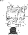
- the state in which the gripper arms 4 and 5 are closed is illustrated in FIG. 6 (the contents 33 have not been inserted yet in this bag mouth opening step).
- the first cam roller 17 passes through the area C of the orientation changing cam 23.
- the pivot frame 3 (and thus the pair of gripper arms 4 and 5 as well) is pivoted for 90° downward, so that the pivot frame 3 is changed into a vertical state and the gripper arms 4 and 5 face downward, and the bag F held by the gripping members 12 is changed to a horizontal orientation.
- the second cam roller 25 is transitioned to the position of the higher portion 32b of the gripper pivot cam 32, and the pair of gripper arms 4 and 5 remain closed. This state is shown in FIG. 5
- the first cam roller 17 is located in the area B of the orientation changing cam 23, and the second cam roller 25 is located at the higher portion 32b of the gripper pivot cam 32, so that the pair of gripper arms 4 and 5 remain in a state of being closed and facing downward (see FIG. 5 ).
- the bag F is filled with the contents 33 (see FIG. 6 ).
- the first cam roller 17 passes through the area D (not shown) of the orientation changing cam 23; and in the course of this movement, the pivot frame 3 (and the pair of gripper arms 4 and 5 as well) are pivoted for 90° upward so as to be changed into a horizontal state, and thus the bag F (filled) held by the gripping members 12 is changed to a vertical orientation.
- the second cam roller 25 is located at the higher portion 32b of the gripper pivot cam 32, and the pair of gripper arms 4 and 5 remain closed. This state is shown in FIG. 6 .
- the first cam roller 17 is located in the area A of the orientation changing cam 23, and the gripper arms 4 and 5 are thus in the horizontal orientation.
- the second cam roller 25 is located at the second movable portion (not shown) of the gripper pivot cam 32. Then, the second movable portion (and thus the second cam roller 25) is lowered, so that the pair of gripper arms 4 and 5 are pivoted outward so as to open, the bag mouth is thus closed and pulled taut by the gripper arms 4 and 5. In this state, the bag mouth is sandwiched by a pair of hot plates and sealed, so that the bag becomes a product bag.
- the gripping members 12 of the gripper device are opened up, so that the product bag falls and moved out of the machine.
- the first cam roller 17 is in the area A of the orientation changing cam 23
- the second cam roller 25 has transitioned to the lower portion 32a of the gripper pivot cam 32, and thus the pair of gripper arms 4 and 5 are in the horizontal state and opened.
- FIGS. 7 and 8 show another gripper device according to the present invention.
- those components that are substantially the same as those of the gripper device of FIGS. 1 and 2 are marked with the same reference numbers and letters.
- the gripper device of FIGS. 7 and 8 differs from the gripper device of FIGS. 1 and 2 in terms of a part of the bag orientation changing mechanism 14. The differences are as follows:
- FIGS. 7 and 8 are, similar to FIGS. 1 and 2 , illustrated such that only the functions of the bag orientation changing mechanism 14 and the orientation changing cam 23 are focused.
- FIG. 7 shows the orientation changing cam 23 which is provided in the above-described area C (which is an area between the bag mouth opening step position and the sealing step position), an orientation changing cam provided in the above-described area D (which is an area between the filling step position and the sealing step position) is not shown in FIG. 7 .
- FIG. 7 shows a gripper device in which the first cam roller 17 is not in contact with the orientation changing cam 23, and the toggle mechanism (comprised of the first pivot arm 21 and the first linking rods 22) maintains the pivot frame 3 in a horizontal state, and the gripper arms 4 and 5 are opened.
- the pivot frame 3 (and the pair of gripper arms 4 and 5 thereon) is pivoted 90° downward, the pivot frame 3 is changed to a vertical state, and gripper arms 4 and 5 face downward, so that the bag F held by the gripping members 12 of the gripper arms 4 and 5 is changed to a horizontal orientation (see FIG. 8 ).
- the linking axis N 1 , the linking axis N 2 , and the pivot axis O 2 all lie in the above-described vertical plane, the holding action produced by the toggle mechanism is exerted on the first pivot arm 21 and the first linking rods 22, so that the pivot frame 3 is held stably in the vertical state.
- the pivot frame 3 is changed from the vertical state (see FIG. 8 ) to a horizontal state (see FIG. 7 ).
- the first cam roller 17 is thus displaced, the first cam levers 16a and 16b are pivoted, and the support shaft 19b is rotated via the support shaft 19a, the large-diameter gear 35, and the small-diameter gear 36; and as a result the first pivot arm 21 is pivoted 180° downward (clockwise in FIG. 8 ) and comes into contact with the stopper 38 to stop its pivoting (see FIG. 7 ).
- the pivot frame 3 (and the pair of gripper arms 4 and 5 thereon) is pivoted 90° upward, the pivot frame 3 is changed to a horizontal state, and the gripper arms 4 and 5 are changed to a horizontal orientation, so that the bag F held by the gripping members 12 of the gripper arms 4 and 5 is changed to a vertical orientation (see FIG. 7 ).
- the holding action produced by the toggle mechanism is exerted on the first pivot arm 21 and the first linking rods 22, so that the pivot frame 3 is held stably in the horizontal state.
- the examples described above are those in which the gripper device of the present invention is applied to a particular rotary bag filling and packaging machine; however, the gripper device of the present invention is applicable to rotary bag filling and packaging machines in which different packaging processing is executed.
- the gripper device according to the present invention is further applicable to other types of bag filling and packaging machines as described below, for example.
Landscapes
- Engineering & Computer Science (AREA)
- Mechanical Engineering (AREA)
- General Engineering & Computer Science (AREA)
- Supplying Of Containers To The Packaging Station (AREA)
Applications Claiming Priority (1)
| Application Number | Priority Date | Filing Date | Title |
|---|---|---|---|
| JP2016210417A JP6746467B2 (ja) | 2016-10-27 | 2016-10-27 | 袋詰め包装機のグリッパー装置 |
Publications (2)
| Publication Number | Publication Date |
|---|---|
| EP3315424A1 true EP3315424A1 (de) | 2018-05-02 |
| EP3315424B1 EP3315424B1 (de) | 2019-01-02 |
Family
ID=60186158
Family Applications (1)
| Application Number | Title | Priority Date | Filing Date |
|---|---|---|---|
| EP17198565.8A Not-in-force EP3315424B1 (de) | 2016-10-27 | 2017-10-26 | Greifervorrichtung für eine beutelfüll- und verpackungsmaschine |
Country Status (6)
| Country | Link |
|---|---|
| US (1) | US10800563B2 (de) |
| EP (1) | EP3315424B1 (de) |
| JP (1) | JP6746467B2 (de) |
| KR (1) | KR20180046352A (de) |
| CN (1) | CN108001757B (de) |
| ES (1) | ES2716162T3 (de) |
Cited By (7)
| Publication number | Priority date | Publication date | Assignee | Title |
|---|---|---|---|---|
| CN109305412A (zh) * | 2018-11-12 | 2019-02-05 | 长沙永乐康仪器设备有限公司 | 一种药品分包机用的包装袋夹持系统 |
| CN111216967A (zh) * | 2020-04-02 | 2020-06-02 | 河南省新之林机电设备有限公司 | 纤维棒料装盒机的空盒输送机构 |
| IT201900006338A1 (it) * | 2019-04-24 | 2020-10-24 | Universal Pack S R L | Metodo per confezionare prodotti e relativo apparato di confezionamento |
| CN112429288A (zh) * | 2020-12-07 | 2021-03-02 | 江西德江隆科技有限公司 | 一种粉体吨包袋自动打包装置 |
| US20220315356A1 (en) * | 2019-05-27 | 2022-10-06 | Mespack, Sl | Conveyor device for conveying flexible containers along a packaging line |
| US11465853B2 (en) * | 2020-04-24 | 2022-10-11 | Pacroft Co., Ltd. | Bag transfer apparatus |
| CN120589268A (zh) * | 2025-08-04 | 2025-09-05 | 晋江市恒松机械制造有限公司 | 一种颗粒零食自动包装设备及方法 |
Families Citing this family (19)
| Publication number | Priority date | Publication date | Assignee | Title |
|---|---|---|---|---|
| US10532841B2 (en) * | 2017-05-24 | 2020-01-14 | Toyo Jidoki Co., Ltd. | Method and apparatus of supplying a bag |
| US11091285B2 (en) * | 2018-10-25 | 2021-08-17 | Nortech, Inc. | Adjustable, inline packaging machine for filling and sealing pouches and method of using same |
| CN110345216B (zh) * | 2019-05-20 | 2024-05-03 | 浙江工业大学 | 一种基于凸轮机构的升降开闭装置 |
| CN111017327A (zh) * | 2019-12-30 | 2020-04-17 | 苏州博古特智造有限公司 | Pe袋夹持组件及pe袋包装系统 |
| KR102166763B1 (ko) * | 2020-03-31 | 2020-10-16 | 이용근 | 식품 포장기용 포장 봉투의 자세 정렬 장치 |
| CN112373825B (zh) * | 2020-10-19 | 2022-04-19 | 沂水县第二水泥厂 | 一种水泥加工用装袋设备 |
| JP7511840B2 (ja) * | 2020-10-21 | 2024-07-08 | ゼネラルパッカー株式会社 | 連包状製袋充填包装機における袋張り装置およびそれを備えた連包状製袋充填包装機 |
| CN112357221A (zh) * | 2020-11-20 | 2021-02-12 | 伍福庆 | 一种包装袋翻转夹取机构及方法 |
| CN112678267A (zh) * | 2020-12-29 | 2021-04-20 | 芜湖哈特机器人产业技术研究院有限公司 | 自动化输送线塑料包装袋的开袋装置 |
| CN112830011B (zh) * | 2021-03-12 | 2024-11-12 | 温州科迪机械有限公司 | 一种折边袋包装机转盘结构 |
| CN113335632B (zh) * | 2021-06-09 | 2023-03-31 | 石家庄市藁城区立峰面业有限公司 | 一种面粉批发用定量分装打包设备 |
| CN113291539B (zh) * | 2021-06-18 | 2022-03-08 | 安徽寒锐新材料有限公司 | 一种钴粉定量装袋用铝箔袋自动供应装置 |
| NL2028767B1 (en) * | 2021-07-16 | 2023-01-23 | Dd Innovations B V | Device for packaging of medicine-units |
| CN114104415B (zh) * | 2021-12-01 | 2023-05-05 | 成都锦城学院 | 一种具有多功能的预开袋电商包装装置 |
| US11684223B1 (en) * | 2022-02-18 | 2023-06-27 | Mz Creations Inc | Toilet |
| CN115367208B (zh) * | 2022-07-26 | 2023-10-24 | 深圳市天麟精密科技有限公司 | 一种自动循环上袋机构 |
| IT202300022254A1 (it) * | 2023-10-24 | 2025-04-24 | Pfm Spa | Gruppo di movimentazione di confezioni per una macchina automatica confezionatrice e relativo metodo |
| CN117508775A (zh) * | 2023-12-07 | 2024-02-06 | 长沙鑫本助剂有限公司 | 一种对硝酸钾批量密封包装装置及包装方法 |
| CN117465767A (zh) * | 2023-12-27 | 2024-01-30 | 山东桂冠机械有限公司 | 一种食品生产用装袋设备 |
Citations (7)
| Publication number | Priority date | Publication date | Assignee | Title |
|---|---|---|---|---|
| JPH03176340A (ja) * | 1989-12-05 | 1991-07-31 | General Patsukaa Kk | 包装機の包装袋グリップ装置 |
| JPH03226434A (ja) * | 1990-01-24 | 1991-10-07 | General Patsukaa Kk | 包装機の包装袋支持角度可変装置 |
| JPH06156440A (ja) | 1992-02-29 | 1994-06-03 | Toyo Jidoki Co Ltd | 自動包装機の袋把持装置 |
| JPH0995318A (ja) | 1995-09-26 | 1997-04-08 | Toyo Jidoki Co Ltd | 自動包装機のグリッパーの開度調整装置 |
| JP3681563B2 (ja) | 1998-12-18 | 2005-08-10 | 株式会社古川製作所 | 包装体の計量方法及びその装置 |
| JP3753930B2 (ja) | 2000-08-03 | 2006-03-08 | 株式会社古川製作所 | 袋詰め包装装置 |
| JP4190692B2 (ja) | 1999-03-11 | 2008-12-03 | 東洋自動機株式会社 | 物品の搬送装置 |
Family Cites Families (4)
| Publication number | Priority date | Publication date | Assignee | Title |
|---|---|---|---|---|
| JPS5969117U (ja) | 1982-10-30 | 1984-05-10 | 株式会社寺岡精工 | 充填包装機 |
| JP5336412B2 (ja) * | 2010-04-01 | 2013-11-06 | 東洋自動機株式会社 | 袋詰め包装機における被包装物充填装置及び充填方法 |
| CN104326119B (zh) * | 2014-09-03 | 2017-02-15 | 宁波铜钱桥食品菜业有限公司 | 一种全自动计量灌装及包装一体机 |
| CN104724324B (zh) * | 2015-03-10 | 2017-06-30 | 湖北任森农业科技发展股份有限公司 | 粉条自动包装机夹袋装置 |
-
2016
- 2016-10-27 JP JP2016210417A patent/JP6746467B2/ja active Active
-
2017
- 2017-08-28 KR KR1020170108515A patent/KR20180046352A/ko not_active Abandoned
- 2017-10-25 US US15/793,734 patent/US10800563B2/en not_active Expired - Fee Related
- 2017-10-26 EP EP17198565.8A patent/EP3315424B1/de not_active Not-in-force
- 2017-10-26 ES ES17198565T patent/ES2716162T3/es active Active
- 2017-10-27 CN CN201711026750.6A patent/CN108001757B/zh not_active Expired - Fee Related
Patent Citations (9)
| Publication number | Priority date | Publication date | Assignee | Title |
|---|---|---|---|---|
| JPH03176340A (ja) * | 1989-12-05 | 1991-07-31 | General Patsukaa Kk | 包装機の包装袋グリップ装置 |
| JPH06102451B2 (ja) | 1989-12-05 | 1994-12-14 | ゼネラルパッカー株式会社 | 包装機の包装袋グリップ装置 |
| JPH03226434A (ja) * | 1990-01-24 | 1991-10-07 | General Patsukaa Kk | 包装機の包装袋支持角度可変装置 |
| JPH072490B2 (ja) | 1990-01-24 | 1995-01-18 | ゼネラルパッカー株式会社 | 包装機の包装袋支持角度可変装置 |
| JPH06156440A (ja) | 1992-02-29 | 1994-06-03 | Toyo Jidoki Co Ltd | 自動包装機の袋把持装置 |
| JPH0995318A (ja) | 1995-09-26 | 1997-04-08 | Toyo Jidoki Co Ltd | 自動包装機のグリッパーの開度調整装置 |
| JP3681563B2 (ja) | 1998-12-18 | 2005-08-10 | 株式会社古川製作所 | 包装体の計量方法及びその装置 |
| JP4190692B2 (ja) | 1999-03-11 | 2008-12-03 | 東洋自動機株式会社 | 物品の搬送装置 |
| JP3753930B2 (ja) | 2000-08-03 | 2006-03-08 | 株式会社古川製作所 | 袋詰め包装装置 |
Cited By (10)
| Publication number | Priority date | Publication date | Assignee | Title |
|---|---|---|---|---|
| CN109305412A (zh) * | 2018-11-12 | 2019-02-05 | 长沙永乐康仪器设备有限公司 | 一种药品分包机用的包装袋夹持系统 |
| CN109305412B (zh) * | 2018-11-12 | 2024-03-29 | 长沙永乐康仪器设备有限公司 | 一种药品分包机用的包装袋夹持系统 |
| IT201900006338A1 (it) * | 2019-04-24 | 2020-10-24 | Universal Pack S R L | Metodo per confezionare prodotti e relativo apparato di confezionamento |
| US20220315356A1 (en) * | 2019-05-27 | 2022-10-06 | Mespack, Sl | Conveyor device for conveying flexible containers along a packaging line |
| US11787645B2 (en) * | 2019-05-27 | 2023-10-17 | Mespack, Sl | Conveyor device for conveying flexible containers along a packaging line |
| CN111216967A (zh) * | 2020-04-02 | 2020-06-02 | 河南省新之林机电设备有限公司 | 纤维棒料装盒机的空盒输送机构 |
| US11465853B2 (en) * | 2020-04-24 | 2022-10-11 | Pacroft Co., Ltd. | Bag transfer apparatus |
| CN112429288A (zh) * | 2020-12-07 | 2021-03-02 | 江西德江隆科技有限公司 | 一种粉体吨包袋自动打包装置 |
| CN120589268A (zh) * | 2025-08-04 | 2025-09-05 | 晋江市恒松机械制造有限公司 | 一种颗粒零食自动包装设备及方法 |
| CN120589268B (zh) * | 2025-08-04 | 2025-11-07 | 晋江市恒松机械制造有限公司 | 一种颗粒零食自动包装设备及方法 |
Also Published As
| Publication number | Publication date |
|---|---|
| CN108001757B (zh) | 2020-10-09 |
| EP3315424B1 (de) | 2019-01-02 |
| ES2716162T3 (es) | 2019-06-10 |
| US20180118393A1 (en) | 2018-05-03 |
| KR20180046352A (ko) | 2018-05-08 |
| US10800563B2 (en) | 2020-10-13 |
| JP2018070200A (ja) | 2018-05-10 |
| CN108001757A (zh) | 2018-05-08 |
| JP6746467B2 (ja) | 2020-08-26 |
Similar Documents
| Publication | Publication Date | Title |
|---|---|---|
| EP3315424B1 (de) | Greifervorrichtung für eine beutelfüll- und verpackungsmaschine | |
| US9221568B2 (en) | Bag transfer device | |
| JP6479622B2 (ja) | グリッパー装置 | |
| US10196164B2 (en) | Container conveying apparatus | |
| CN103204277B (zh) | 产品袋取出装置 | |
| US9221569B2 (en) | Bag transfer device | |
| EP1247767A1 (de) | Vorrichtung zum Fördern von Beuteln und eine endlose Kette mit Greifern für eine Füll- und Verschliessmaschine | |
| US8261785B2 (en) | Gripper for an automatic bag filling apparatus | |
| JP6758776B2 (ja) | 容器搬送装置 | |
| CN111661808B (zh) | 一种容器抓手 | |
| JPH0731603U (ja) | プラスチックフィルム自動包装機械のグリッパ | |
| US11465853B2 (en) | Bag transfer apparatus | |
| US7422212B2 (en) | Transfer wheel | |
| JP2014118175A (ja) | 袋体把持開閉搬送装置 | |
| US6901724B2 (en) | Method and unit for transferring wrappings | |
| JP2001113494A (ja) | ログペーパー切断装置のログペーパークランプ装置 | |
| TW202602743A (zh) | 摺蓋裝置 | |
| EA045851B1 (ru) | Система размещения банок в машине для обработки банок | |
| JPH0227205B2 (de) |
Legal Events
| Date | Code | Title | Description |
|---|---|---|---|
| PUAI | Public reference made under article 153(3) epc to a published international application that has entered the european phase |
Free format text: ORIGINAL CODE: 0009012 |
|
| STAA | Information on the status of an ep patent application or granted ep patent |
Free format text: STATUS: THE APPLICATION HAS BEEN PUBLISHED |
|
| AK | Designated contracting states |
Kind code of ref document: A1 Designated state(s): AL AT BE BG CH CY CZ DE DK EE ES FI FR GB GR HR HU IE IS IT LI LT LU LV MC MK MT NL NO PL PT RO RS SE SI SK SM TR |
|
| AX | Request for extension of the european patent |
Extension state: BA ME |
|
| STAA | Information on the status of an ep patent application or granted ep patent |
Free format text: STATUS: REQUEST FOR EXAMINATION WAS MADE |
|
| 17P | Request for examination filed |
Effective date: 20180523 |
|
| RBV | Designated contracting states (corrected) |
Designated state(s): AL AT BE BG CH CY CZ DE DK EE ES FI FR GB GR HR HU IE IS IT LI LT LU LV MC MK MT NL NO PL PT RO RS SE SI SK SM TR |
|
| RIC1 | Information provided on ipc code assigned before grant |
Ipc: B65B 43/46 20060101ALI20180615BHEP Ipc: B65B 43/62 20060101ALI20180615BHEP Ipc: B65B 59/00 20060101ALI20180615BHEP Ipc: B65B 43/32 20060101AFI20180615BHEP Ipc: B65B 43/30 20060101ALI20180615BHEP |
|
| GRAP | Despatch of communication of intention to grant a patent |
Free format text: ORIGINAL CODE: EPIDOSNIGR1 |
|
| STAA | Information on the status of an ep patent application or granted ep patent |
Free format text: STATUS: GRANT OF PATENT IS INTENDED |
|
| INTG | Intention to grant announced |
Effective date: 20180822 |
|
| GRAS | Grant fee paid |
Free format text: ORIGINAL CODE: EPIDOSNIGR3 |
|
| GRAA | (expected) grant |
Free format text: ORIGINAL CODE: 0009210 |
|
| STAA | Information on the status of an ep patent application or granted ep patent |
Free format text: STATUS: THE PATENT HAS BEEN GRANTED |
|
| AK | Designated contracting states |
Kind code of ref document: B1 Designated state(s): AL AT BE BG CH CY CZ DE DK EE ES FI FR GB GR HR HU IE IS IT LI LT LU LV MC MK MT NL NO PL PT RO RS SE SI SK SM TR |
|
| REG | Reference to a national code |
Ref country code: GB Ref legal event code: FG4D |
|
| REG | Reference to a national code |
Ref country code: CH Ref legal event code: EP Ref country code: AT Ref legal event code: REF Ref document number: 1084068 Country of ref document: AT Kind code of ref document: T Effective date: 20190115 |
|
| REG | Reference to a national code |
Ref country code: IE Ref legal event code: FG4D |
|
| REG | Reference to a national code |
Ref country code: DE Ref legal event code: R096 Ref document number: 602017001700 Country of ref document: DE |
|
| REG | Reference to a national code |
Ref country code: NL Ref legal event code: MP Effective date: 20190102 |
|
| REG | Reference to a national code |
Ref country code: LT Ref legal event code: MG4D |
|
| REG | Reference to a national code |
Ref country code: ES Ref legal event code: FG2A Ref document number: 2716162 Country of ref document: ES Kind code of ref document: T3 Effective date: 20190610 |
|
| REG | Reference to a national code |
Ref country code: AT Ref legal event code: MK05 Ref document number: 1084068 Country of ref document: AT Kind code of ref document: T Effective date: 20190102 |
|
| PG25 | Lapsed in a contracting state [announced via postgrant information from national office to epo] |
Ref country code: NL Free format text: LAPSE BECAUSE OF FAILURE TO SUBMIT A TRANSLATION OF THE DESCRIPTION OR TO PAY THE FEE WITHIN THE PRESCRIBED TIME-LIMIT Effective date: 20190102 |
|
| PG25 | Lapsed in a contracting state [announced via postgrant information from national office to epo] |
Ref country code: NO Free format text: LAPSE BECAUSE OF FAILURE TO SUBMIT A TRANSLATION OF THE DESCRIPTION OR TO PAY THE FEE WITHIN THE PRESCRIBED TIME-LIMIT Effective date: 20190402 Ref country code: FI Free format text: LAPSE BECAUSE OF FAILURE TO SUBMIT A TRANSLATION OF THE DESCRIPTION OR TO PAY THE FEE WITHIN THE PRESCRIBED TIME-LIMIT Effective date: 20190102 Ref country code: SE Free format text: LAPSE BECAUSE OF FAILURE TO SUBMIT A TRANSLATION OF THE DESCRIPTION OR TO PAY THE FEE WITHIN THE PRESCRIBED TIME-LIMIT Effective date: 20190102 Ref country code: PT Free format text: LAPSE BECAUSE OF FAILURE TO SUBMIT A TRANSLATION OF THE DESCRIPTION OR TO PAY THE FEE WITHIN THE PRESCRIBED TIME-LIMIT Effective date: 20190502 Ref country code: PL Free format text: LAPSE BECAUSE OF FAILURE TO SUBMIT A TRANSLATION OF THE DESCRIPTION OR TO PAY THE FEE WITHIN THE PRESCRIBED TIME-LIMIT Effective date: 20190102 Ref country code: LT Free format text: LAPSE BECAUSE OF FAILURE TO SUBMIT A TRANSLATION OF THE DESCRIPTION OR TO PAY THE FEE WITHIN THE PRESCRIBED TIME-LIMIT Effective date: 20190102 |
|
| PG25 | Lapsed in a contracting state [announced via postgrant information from national office to epo] |
Ref country code: LV Free format text: LAPSE BECAUSE OF FAILURE TO SUBMIT A TRANSLATION OF THE DESCRIPTION OR TO PAY THE FEE WITHIN THE PRESCRIBED TIME-LIMIT Effective date: 20190102 Ref country code: HR Free format text: LAPSE BECAUSE OF FAILURE TO SUBMIT A TRANSLATION OF THE DESCRIPTION OR TO PAY THE FEE WITHIN THE PRESCRIBED TIME-LIMIT Effective date: 20190102 Ref country code: BG Free format text: LAPSE BECAUSE OF FAILURE TO SUBMIT A TRANSLATION OF THE DESCRIPTION OR TO PAY THE FEE WITHIN THE PRESCRIBED TIME-LIMIT Effective date: 20190402 Ref country code: GR Free format text: LAPSE BECAUSE OF FAILURE TO SUBMIT A TRANSLATION OF THE DESCRIPTION OR TO PAY THE FEE WITHIN THE PRESCRIBED TIME-LIMIT Effective date: 20190403 Ref country code: IS Free format text: LAPSE BECAUSE OF FAILURE TO SUBMIT A TRANSLATION OF THE DESCRIPTION OR TO PAY THE FEE WITHIN THE PRESCRIBED TIME-LIMIT Effective date: 20190502 Ref country code: RS Free format text: LAPSE BECAUSE OF FAILURE TO SUBMIT A TRANSLATION OF THE DESCRIPTION OR TO PAY THE FEE WITHIN THE PRESCRIBED TIME-LIMIT Effective date: 20190102 |
|
| REG | Reference to a national code |
Ref country code: DE Ref legal event code: R097 Ref document number: 602017001700 Country of ref document: DE |
|
| PG25 | Lapsed in a contracting state [announced via postgrant information from national office to epo] |
Ref country code: AT Free format text: LAPSE BECAUSE OF FAILURE TO SUBMIT A TRANSLATION OF THE DESCRIPTION OR TO PAY THE FEE WITHIN THE PRESCRIBED TIME-LIMIT Effective date: 20190102 Ref country code: DK Free format text: LAPSE BECAUSE OF FAILURE TO SUBMIT A TRANSLATION OF THE DESCRIPTION OR TO PAY THE FEE WITHIN THE PRESCRIBED TIME-LIMIT Effective date: 20190102 Ref country code: EE Free format text: LAPSE BECAUSE OF FAILURE TO SUBMIT A TRANSLATION OF THE DESCRIPTION OR TO PAY THE FEE WITHIN THE PRESCRIBED TIME-LIMIT Effective date: 20190102 Ref country code: RO Free format text: LAPSE BECAUSE OF FAILURE TO SUBMIT A TRANSLATION OF THE DESCRIPTION OR TO PAY THE FEE WITHIN THE PRESCRIBED TIME-LIMIT Effective date: 20190102 Ref country code: CZ Free format text: LAPSE BECAUSE OF FAILURE TO SUBMIT A TRANSLATION OF THE DESCRIPTION OR TO PAY THE FEE WITHIN THE PRESCRIBED TIME-LIMIT Effective date: 20190102 Ref country code: AL Free format text: LAPSE BECAUSE OF FAILURE TO SUBMIT A TRANSLATION OF THE DESCRIPTION OR TO PAY THE FEE WITHIN THE PRESCRIBED TIME-LIMIT Effective date: 20190102 Ref country code: SK Free format text: LAPSE BECAUSE OF FAILURE TO SUBMIT A TRANSLATION OF THE DESCRIPTION OR TO PAY THE FEE WITHIN THE PRESCRIBED TIME-LIMIT Effective date: 20190102 |
|
| PLBE | No opposition filed within time limit |
Free format text: ORIGINAL CODE: 0009261 |
|
| STAA | Information on the status of an ep patent application or granted ep patent |
Free format text: STATUS: NO OPPOSITION FILED WITHIN TIME LIMIT |
|
| PG25 | Lapsed in a contracting state [announced via postgrant information from national office to epo] |
Ref country code: SM Free format text: LAPSE BECAUSE OF FAILURE TO SUBMIT A TRANSLATION OF THE DESCRIPTION OR TO PAY THE FEE WITHIN THE PRESCRIBED TIME-LIMIT Effective date: 20190102 |
|
| 26N | No opposition filed |
Effective date: 20191003 |
|
| PG25 | Lapsed in a contracting state [announced via postgrant information from national office to epo] |
Ref country code: TR Free format text: LAPSE BECAUSE OF FAILURE TO SUBMIT A TRANSLATION OF THE DESCRIPTION OR TO PAY THE FEE WITHIN THE PRESCRIBED TIME-LIMIT Effective date: 20190102 |
|
| PG25 | Lapsed in a contracting state [announced via postgrant information from national office to epo] |
Ref country code: MC Free format text: LAPSE BECAUSE OF FAILURE TO SUBMIT A TRANSLATION OF THE DESCRIPTION OR TO PAY THE FEE WITHIN THE PRESCRIBED TIME-LIMIT Effective date: 20190102 |
|
| PG25 | Lapsed in a contracting state [announced via postgrant information from national office to epo] |
Ref country code: LU Free format text: LAPSE BECAUSE OF NON-PAYMENT OF DUE FEES Effective date: 20191026 |
|
| REG | Reference to a national code |
Ref country code: BE Ref legal event code: MM Effective date: 20191031 |
|
| PG25 | Lapsed in a contracting state [announced via postgrant information from national office to epo] |
Ref country code: BE Free format text: LAPSE BECAUSE OF NON-PAYMENT OF DUE FEES Effective date: 20191031 |
|
| PG25 | Lapsed in a contracting state [announced via postgrant information from national office to epo] |
Ref country code: IE Free format text: LAPSE BECAUSE OF NON-PAYMENT OF DUE FEES Effective date: 20191026 |
|
| PG25 | Lapsed in a contracting state [announced via postgrant information from national office to epo] |
Ref country code: CY Free format text: LAPSE BECAUSE OF FAILURE TO SUBMIT A TRANSLATION OF THE DESCRIPTION OR TO PAY THE FEE WITHIN THE PRESCRIBED TIME-LIMIT Effective date: 20190102 |
|
| REG | Reference to a national code |
Ref country code: CH Ref legal event code: PL |
|
| PG25 | Lapsed in a contracting state [announced via postgrant information from national office to epo] |
Ref country code: CH Free format text: LAPSE BECAUSE OF FAILURE TO SUBMIT A TRANSLATION OF THE DESCRIPTION OR TO PAY THE FEE WITHIN THE PRESCRIBED TIME-LIMIT Effective date: 20201031 Ref country code: LI Free format text: LAPSE BECAUSE OF FAILURE TO SUBMIT A TRANSLATION OF THE DESCRIPTION OR TO PAY THE FEE WITHIN THE PRESCRIBED TIME-LIMIT Effective date: 20201031 |
|
| PG25 | Lapsed in a contracting state [announced via postgrant information from national office to epo] |
Ref country code: MT Free format text: LAPSE BECAUSE OF FAILURE TO SUBMIT A TRANSLATION OF THE DESCRIPTION OR TO PAY THE FEE WITHIN THE PRESCRIBED TIME-LIMIT Effective date: 20190102 Ref country code: HU Free format text: LAPSE BECAUSE OF FAILURE TO SUBMIT A TRANSLATION OF THE DESCRIPTION OR TO PAY THE FEE WITHIN THE PRESCRIBED TIME-LIMIT; INVALID AB INITIO Effective date: 20171026 |
|
| PG25 | Lapsed in a contracting state [announced via postgrant information from national office to epo] |
Ref country code: SI Free format text: LAPSE BECAUSE OF FAILURE TO SUBMIT A TRANSLATION OF THE DESCRIPTION OR TO PAY THE FEE WITHIN THE PRESCRIBED TIME-LIMIT Effective date: 20190102 |
|
| PGFP | Annual fee paid to national office [announced via postgrant information from national office to epo] |
Ref country code: GB Payment date: 20211022 Year of fee payment: 5 Ref country code: DE Payment date: 20211020 Year of fee payment: 5 Ref country code: ES Payment date: 20211224 Year of fee payment: 5 |
|
| PGFP | Annual fee paid to national office [announced via postgrant information from national office to epo] |
Ref country code: IT Payment date: 20211028 Year of fee payment: 5 Ref country code: FR Payment date: 20211022 Year of fee payment: 5 |
|
| PG25 | Lapsed in a contracting state [announced via postgrant information from national office to epo] |
Ref country code: MK Free format text: LAPSE BECAUSE OF FAILURE TO SUBMIT A TRANSLATION OF THE DESCRIPTION OR TO PAY THE FEE WITHIN THE PRESCRIBED TIME-LIMIT Effective date: 20190102 |
|
| REG | Reference to a national code |
Ref country code: DE Ref legal event code: R119 Ref document number: 602017001700 Country of ref document: DE |
|
| GBPC | Gb: european patent ceased through non-payment of renewal fee |
Effective date: 20221026 |
|
| PG25 | Lapsed in a contracting state [announced via postgrant information from national office to epo] |
Ref country code: FR Free format text: LAPSE BECAUSE OF NON-PAYMENT OF DUE FEES Effective date: 20221031 Ref country code: DE Free format text: LAPSE BECAUSE OF NON-PAYMENT OF DUE FEES Effective date: 20230503 |
|
| PG25 | Lapsed in a contracting state [announced via postgrant information from national office to epo] |
Ref country code: IT Free format text: LAPSE BECAUSE OF NON-PAYMENT OF DUE FEES Effective date: 20221026 Ref country code: GB Free format text: LAPSE BECAUSE OF NON-PAYMENT OF DUE FEES Effective date: 20221026 |
|
| REG | Reference to a national code |
Ref country code: ES Ref legal event code: FD2A Effective date: 20231201 |
|
| PG25 | Lapsed in a contracting state [announced via postgrant information from national office to epo] |
Ref country code: ES Free format text: LAPSE BECAUSE OF NON-PAYMENT OF DUE FEES Effective date: 20221027 |
|
| PG25 | Lapsed in a contracting state [announced via postgrant information from national office to epo] |
Ref country code: ES Free format text: LAPSE BECAUSE OF NON-PAYMENT OF DUE FEES Effective date: 20221027 |