EP3315680A2 - Bauplatte für die erstellung eines bauwerks, herstellungsverfahren einer in die bauplatte integrierten vorrichtung, und herstellungsverfahren einer solchen platte - Google Patents
Bauplatte für die erstellung eines bauwerks, herstellungsverfahren einer in die bauplatte integrierten vorrichtung, und herstellungsverfahren einer solchen platte Download PDFInfo
- Publication number
- EP3315680A2 EP3315680A2 EP17199030.2A EP17199030A EP3315680A2 EP 3315680 A2 EP3315680 A2 EP 3315680A2 EP 17199030 A EP17199030 A EP 17199030A EP 3315680 A2 EP3315680 A2 EP 3315680A2
- Authority
- EP
- European Patent Office
- Prior art keywords
- devices
- formwork
- filling
- plate
- manufacturing
- Prior art date
- Legal status (The legal status is an assumption and is not a legal conclusion. Google has not performed a legal analysis and makes no representation as to the accuracy of the status listed.)
- Granted
Links
Images




Classifications
-
- E—FIXED CONSTRUCTIONS
- E04—BUILDING
- E04B—GENERAL BUILDING CONSTRUCTIONS; WALLS, e.g. PARTITIONS; ROOFS; FLOORS; CEILINGS; INSULATION OR OTHER PROTECTION OF BUILDINGS
- E04B5/00—Floors; Floor construction with regard to insulation; Connections specially adapted therefor
- E04B5/02—Load-carrying floor structures formed substantially of prefabricated units
- E04B5/04—Load-carrying floor structures formed substantially of prefabricated units with beams or slabs of concrete or other stone-like material, e.g. asbestos cement
-
- B—PERFORMING OPERATIONS; TRANSPORTING
- B28—WORKING CEMENT, CLAY, OR STONE
- B28B—SHAPING CLAY OR OTHER CERAMIC COMPOSITIONS; SHAPING SLAG; SHAPING MIXTURES CONTAINING CEMENTITIOUS MATERIAL, e.g. PLASTER
- B28B23/00—Arrangements specially adapted for the production of shaped articles with elements wholly or partly embedded in the moulding material; Production of reinforced objects
- B28B23/0081—Embedding aggregates to obtain particular properties
- B28B23/0087—Lightweight aggregates for making lightweight articles
-
- B—PERFORMING OPERATIONS; TRANSPORTING
- B28—WORKING CEMENT, CLAY, OR STONE
- B28B—SHAPING CLAY OR OTHER CERAMIC COMPOSITIONS; SHAPING SLAG; SHAPING MIXTURES CONTAINING CEMENTITIOUS MATERIAL, e.g. PLASTER
- B28B3/00—Producing shaped articles from the material by using presses; Presses specially adapted therefor
- B28B3/12—Producing shaped articles from the material by using presses; Presses specially adapted therefor wherein one or more rollers exert pressure on the material
- B28B3/14—Producing shaped articles from the material by using presses; Presses specially adapted therefor wherein one or more rollers exert pressure on the material with co-operating pocketed rollers
-
- B—PERFORMING OPERATIONS; TRANSPORTING
- B30—PRESSES
- B30B—PRESSES IN GENERAL
- B30B11/00—Presses specially adapted for forming shaped articles from material in particulate or plastic state, e.g. briquetting presses, tabletting presses
- B30B11/16—Presses specially adapted for forming shaped articles from material in particulate or plastic state, e.g. briquetting presses, tabletting presses using pocketed rollers, e.g. two co-operating pocketed rollers
-
- E—FIXED CONSTRUCTIONS
- E04—BUILDING
- E04C—STRUCTURAL ELEMENTS; BUILDING MATERIALS
- E04C2/00—Building elements of relatively thin form for the construction of parts of buildings, e.g. sheet materials, slabs, or panels
- E04C2/02—Building elements of relatively thin form for the construction of parts of buildings, e.g. sheet materials, slabs, or panels characterised by specified materials
- E04C2/04—Building elements of relatively thin form for the construction of parts of buildings, e.g. sheet materials, slabs, or panels characterised by specified materials of concrete or other stone-like material; of asbestos cement; of cement and other mineral fibres
- E04C2/044—Building elements of relatively thin form for the construction of parts of buildings, e.g. sheet materials, slabs, or panels characterised by specified materials of concrete or other stone-like material; of asbestos cement; of cement and other mineral fibres of concrete
-
- E—FIXED CONSTRUCTIONS
- E04—BUILDING
- E04C—STRUCTURAL ELEMENTS; BUILDING MATERIALS
- E04C2/00—Building elements of relatively thin form for the construction of parts of buildings, e.g. sheet materials, slabs, or panels
- E04C2/30—Building elements of relatively thin form for the construction of parts of buildings, e.g. sheet materials, slabs, or panels characterised by the shape or structure
- E04C2/38—Building elements of relatively thin form for the construction of parts of buildings, e.g. sheet materials, slabs, or panels characterised by the shape or structure with attached ribs, flanges, or the like, e.g. framed panels
Definitions
- the invention relates to building plates for the realization of work, and more particularly slabs and walls.
- plates are used which may be slabs for the foundations of the structure or walls to construct walls and partitions.
- the walls are placed vertically and the slabs are, for their part, placed on the ground or a support located above the ground to make floors.
- Slabs are usually made of concrete.
- the malleable concrete is then poured into a formwork and its curing is waited for to obtain a flat surface adapted to receive a floor, for example a wooden floor, in tiling, ...
- these slabs are heavy and must rest on a suitable supporting structure.
- lightweight concrete composed of cement, water, aggregates, and polystyrene beads can be used.
- aerated concrete in which air is injected when the concrete is in the liquid state before hardening to create cavities. But we can not control precisely the density of the slabs thus obtained. In addition, these slabs do not provide sufficient thermal and acoustic insulation.
- slabs made by depositing dry aggregates (usually clay), that is to say without cement, on a support intended for to support a floor.
- the support may be a ground, when the floor is made in a cellar of a building, or the support may be a concrete slab, a floor of wood or tiling for living rooms located above the ground. But these dry slabs do not offer sufficient acoustic and thermal insulation either.
- An object of the invention is to overcome these disadvantages, and more particularly to provide means for improving the acoustic and thermal insulation of structures.
- a construction plate for the construction of a structure comprising a formwork delimiting a filling zone, and a plurality of devices housed within the filling zone.
- each device has a body defining at least one closed cavity.
- any type of plate such as a wall or a slab, can be made comprising a residual volume of air effective to increase the acoustic and thermal insulation of the structure.
- the residual volume corresponds to the sum of the volumes defined by the closed cavities of the devices. It is thus possible to control the acoustic and thermal properties of the plates produced because the residual volume can be precisely determined.
- the plate may comprise a material comprising a binder and aggregates aggregated within the binder, the material being housed within the filling zone and the devices being embedded in the material.
- the binder may comprise a cement.
- the body of the devices can be coated with an adhesive film to mechanically link the devices together and with the formwork.
- the adhesive film may comprise a mortar.
- the body of the devices may comprise a ceramic material.
- the body of the devices may comprise a plastic material.
- the plate may comprise a protective layer covering the filling area.
- the method may comprise a filling step in which a material comprising a binder and granules is poured into the filling zone to embed the devices within the material.
- the structure can be a building, a house, a shed, ...
- the plate 1 comprises a formwork 2 and several devices 3.
- the formwork 2 delimits a filling zone 4.
- the formwork 2 can have a varied shape and a thickness varied.
- the formwork 2 has at least one longitudinal element 5 to 8, that is to say having a length greater than its height and its width.
- the formwork 2 may comprise a single longitudinal element 5 to 8 describing a closed curve, such as a circle, an ellipse, an ovoid curve, a triangle, a quadrilateral or a polygonal curve.
- the formwork 2 comprises four longitudinal elements 5 to 8 fixed together to describe a closed curve in order to define the filling area 4.
- a parallelepiped formwork 2 is obtained.
- the formwork 2 is open to allow filling of the filling zone 4 with the devices 3.
- the longitudinal elements 5 to 8 may be fixed together so that the formwork 2 has two opposite planar surfaces S, T These surfaces S, T may be open or partially closed by two additional formwork elements, such as lids fixed on the longitudinal elements 5, 8.
- the formwork 2 may comprise a single cover 16, as illustrated in FIG. figure 7 to completely or partially close a surface S, T.
- the formwork 2 comprises two lids respectively closing the two surfaces S, T, partially or totally.
- a longitudinal member 5 to 8 may be a beam, a wall or a partition.
- the formwork 2 is intended to be placed on a supporting structure 9.
- the supporting structure 9 may be the ground, a floor, a concrete slab.
- the longitudinal elements 5 to 8 may be curved, as well as the covers if necessary, to form a curved formwork 2 adapted to the irregularities of the supporting structure 9.
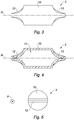
- each device 3 has a body 10 delimiting at least one closed cavity 11, illustrated in FIG. figure 4 .
- Cavity 11 means an empty space housed inside the body 10 of the device 3.
- closed cavity 11 is meant a void space enclosed within the device 3.
- the cavity 11 forms a volume containing a gas, preferably air.
- the bodies 10 of the devices 3 occupy a volume, denoted occupancy volume, within the plate 1, and the cavities 11 guarantee an unoccupied volume, noted residual volume, corresponding to the sum of the volumes defined by the cavities 11 of each of the 3.
- a plate 1 having a residual volume which improves the acoustic and thermal properties.
- plates 1 that can be used to make walls or slabs. Due to the thickness of the bodies 10 of the devices 3, there is provided a plate 1 having sufficient compressive strength. When the bodies 10 are made of ceramic, plates 1 having good fire resistance are provided because the ceramic is a non-combustible material. Due to the residual volume created by the cavities 11 in the devices 3, the thermal properties of the plate 1 are increased because the air is a thermal insulator. Furthermore, the thickness of the walls of the bodies 10 of the devices 3 and the cavities 11 located within the walls contribute to improving the acoustic properties of the plates 1. In fact, the wall succession, cavity 11, wall, of the devices 3 makes it possible to In addition, the residual volume created by the set of devices 3 lightens the plate 1.
- spaces are created between the devices 3, which provides a drainage property to let passing gravity liquids that could infiltrate the plate 1. It is also possible to know precisely the volume of each cavity 11 and thus determine a specific residual volume, which allows to control the thermal properties, acoustic and density of the plate 1.
- the device 3 has a body 10 delimiting at least one closed cavity 11.
- the body 10 of the device 3 is particularly liquid-tight, for example to the water or mortar in the liquid phase before curing.
- the body 10 of the device 3 extends along a longitudinal axis A of the device 3 and has two closed ends 12, 13.
- the closed ends 12, 13 may each have a linear shape.
- the ends 12, 13 are parallel to each other.
- the body 10 of the device 3 has a cylindrical shape.
- cylinder is here understood to mean a solid bounded by a cylindrical surface generated by a line, referred to as a generator, running through a closed planar curve, denoted as a director, and two planes intersecting the generatrices.
- the body 10 may have a shape of a tube.
- the body of the device 3 can also delimit several cavities 11, communicating with each other or not.
- the closed cavities 11 prevent the devices 3 from nesting into each other, regardless of their size and shape.
- the dimensions of the devices 3 are adjustable.
- each device 8 has a length of between 30 and 100 mm, and preferably equal to 50 mm.
- the length of the device 3 corresponds to the distance between the two ends 12, 13.
- the length of the cylindrical portion of the body 3 may be between 20 and 90 mm. In this case, each end 12, 13 may have a length equal to 5 mm.
- the outer diameter of the cylindrical portion of the body 3 may be between 10 and 40 mm.
- the internal diameter of the cylindrical portion of the body 3 may be between 8 and 38 mm.
- the thickness of the wall of the body 3 may be equal to 2 mm.
- the plate 1 comprises only devices 3 each having a closed cavity 11.
- the thickness of the walls, the internal and external diameter and the length of the bodies 10 of the devices 3 can be varied to obtain thermal, acoustic and densities adjusted according to needs.
- the plate 1 comprises a material 14 comprising a binder and aggregates aggregated within the binder.
- the material 14 is housed within the filling zone 4 and the devices 3 are embedded in the within the material 14.
- the binder may comprise a cement. Thanks to the bodies 10 of the devices which delimit at least one closed cavity 11, it is ensured that the plate 1 has a residual volume, since the devices 3 are sealed to the material 14 and prevents it from penetrating inside the cavities 11. material 14 can increase the compressive strength of the plate 1.
- the body 10 of the devices 3 is coated with an adhesive film 15 to mechanically link the devices 3 to each other and to the formwork 2
- the adhesive film 15 may comprise a mortar.
- the devices 3 are coated with an adhesive film 15 which surrounds the outer surface of the body 10 of the devices 3.
- the devices 3 For coating the bodies of adhesive film devices 15, the devices 3 may for example be poured into mortar and a sieve used to remove excess mortar. In this case, an external film of mortar 15 coats the outer surface of the devices 3. Thus, the closed cavity 11 is protected and its volume remains unchanged.
- the plate 1 may comprise a protective cover 16 covering the filling area 4.
- the protective cover 16 may be a cover as defined above. The protective cover 16 protects the devices 3 during the transport of the plate 1, to prevent the bodies 10 break.
- the body of the devices 3 may comprise a ceramic material. Ceramics offer good mechanical resistance to compression, and allows plates 1 to be lighter than devices made of metal.
- the devices 8 can also be made in cement, or mortar, of raw clay, which are, like ceramics, materials having good mechanical resistance to compression.
- the devices 3 may be made of metal or plastic.
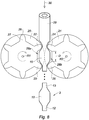
- the method comprises a step of using a system comprising two toothed wheels 20, 21. Also shown on the figure 12 , a front view of one of the wheels 20, 21.
- Each wheel 20, 21 comprises at least two teeth 22 to 25.
- a wheel 20, 21 comprises six teeth, as shown in FIG. figure 8 .
- a tooth 22 to 25 comprises a head 26 located at its top and a base 27.
- the teeth 22 to 25 of the same wheel 20, 21 are placed at the periphery of the wheel 20, 21 and at a distance D 1 the other. The distance D separates two bases 27 from two adjacent teeth 22, 23.
- the distance D may be identical between two adjacent teeth of the wheel 20, 21.
- the neighboring teeth 22, 23 and 24, 25 of a same wheel 20, 21 delimit a housing 28a, 28b for receiving the body 10 of a device 3.
- the wheels 20, 21 are mounted to rotate about axes of rotations R1, R2, which are parallel.
- the wheels 20, 21 are further rotated in opposite directions and at the same speed of rotation.
- the wheels 20, 21 are placed one beside the other and so that two teeth 22, 24 of the two respective wheels 20, 21 are facing each other whenever the wheels 20, 21 rotate one revolution.
- the toothed wheels 20, 21 are rotated and the hollow tube 29 is translated in a direction 30 between the two wheels 20, 21.
- the method is particularly suitable for manufacturing devices 3 whose body 10 is ceramic.
- the ceramic is malleable before a firing step so as to form the closed cavity 11 within the device 3, and because it becomes solid after firing to give the desired strength to the plate 1.
- the axes of rotation R1, R2 are horizontal so as to use the force of gravity to produce the devices 3.
- the axes of rotation R1, R2 are vertical.
- first teeth 23, 25 which are opposite one another cooperate with one another to form the first end 12 of a first device 3a.
- the formation of the first end 12 is performed by crushing the malleable hollow tube 29, which closes a first end of the cavity 11.
- the hollow tube 29 is found housed in the housings 28a, 28b of the wheels 20, 21 and is not crushed, which forms the body 10 of the first device 3a.
- two second teeth 22, 24 which are in facing relation cooperate with each other to form the second end 13 of the first device 3a.
- the formation of the second end 13 is also performed by crushing the malleable hollow tube 29, which closes the second end of the cavity 11.
- the wheels 20, 21 continue to rotate and advance the hollow tube 29.
- the second teeth 22, 24 intersect the second end 13 and push in the direction of translation 30 the first device 3a, while a second device 3b is in course of realization.
- the head 26 of the teeth 22 to 25 may be pointed so as to form the ends 12, 13 of the devices 3 and to cut the hollow tube 29 to separate the devices 3a, 3b.
- the method comprises a filling step in which is poured within the filling zone 4 a material 14 comprising a binder and granules for embedding the devices 3 within the material 14.
- the invention which has just been described makes it possible to provide building elements that are particularly suitable for dwellings, such as buildings or houses.
Landscapes
- Engineering & Computer Science (AREA)
- Architecture (AREA)
- Structural Engineering (AREA)
- Civil Engineering (AREA)
- Mechanical Engineering (AREA)
- Ceramic Engineering (AREA)
- Chemical & Material Sciences (AREA)
- Manufacturing & Machinery (AREA)
- Physics & Mathematics (AREA)
- Electromagnetism (AREA)
- Building Environments (AREA)
- Manufacturing Of Tubular Articles Or Embedded Moulded Articles (AREA)
- Forms Removed On Construction Sites Or Auxiliary Members Thereof (AREA)
- Panels For Use In Building Construction (AREA)
Applications Claiming Priority (1)
| Application Number | Priority Date | Filing Date | Title |
|---|---|---|---|
| FR1660420A FR3058169B1 (fr) | 2016-10-27 | 2016-10-27 | Plaque de construction pour la realisation d'ouvrage, procede de fabrication d'un dispositif integre dans la plaque de construction et procede de fabrication d'une telle plaque |
Publications (4)
| Publication Number | Publication Date |
|---|---|
| EP3315680A2 true EP3315680A2 (de) | 2018-05-02 |
| EP3315680A3 EP3315680A3 (de) | 2018-08-22 |
| EP3315680B1 EP3315680B1 (de) | 2020-04-01 |
| EP3315680B8 EP3315680B8 (de) | 2020-05-13 |
Family
ID=58162739
Family Applications (2)
| Application Number | Title | Priority Date | Filing Date |
|---|---|---|---|
| EP17199030.2A Active EP3315680B8 (de) | 2016-10-27 | 2017-10-27 | Bauplatte für die erstellung eines bauwerks und herstellungsverfahren einer solchen platte |
| EP17199047.6A Withdrawn EP3315681A1 (de) | 2016-10-27 | 2017-10-27 | Herstellungsverfahren eines hohlkörpers |
Family Applications After (1)
| Application Number | Title | Priority Date | Filing Date |
|---|---|---|---|
| EP17199047.6A Withdrawn EP3315681A1 (de) | 2016-10-27 | 2017-10-27 | Herstellungsverfahren eines hohlkörpers |
Country Status (2)
| Country | Link |
|---|---|
| EP (2) | EP3315680B8 (de) |
| FR (2) | FR3058169B1 (de) |
Family Cites Families (15)
| Publication number | Priority date | Publication date | Assignee | Title |
|---|---|---|---|---|
| US1206752A (en) * | 1916-10-07 | 1916-11-28 | Davis Construction Company Inc | Reinforced concrete construction for floors and ceilings. |
| BE464442A (de) * | 1941-10-27 | |||
| US2477852A (en) * | 1945-07-04 | 1949-08-02 | Owens Corning Fiberglass Corp | Structural panel construction |
| CH470949A (de) * | 1967-01-31 | 1969-04-15 | Weibel & Dall O | Verfahren zur Herstellung von Hohlkugeln aus keramischem Material und Vorrichtung zur Durchführung des Verfahrens |
| US3831335A (en) * | 1972-11-15 | 1974-08-27 | T Ary | Prefabricated cast reinforced framed concrete wall section with clips to attach the frame to the reinforcing |
| US4068429A (en) * | 1975-04-21 | 1978-01-17 | Moore Alvin E | Wall and wall part |
| WO1988001325A1 (en) * | 1986-08-14 | 1988-02-25 | Unan Pty Ltd. | Modular building system |
| DK166462B1 (da) * | 1990-10-01 | 1993-05-24 | Joergen Breuning | Plant, dobbeltspaendt jernbetonhuldaek og fremgangsmaade til fremstilling heraf |
| JP2004190332A (ja) * | 2002-12-11 | 2004-07-08 | Tomuko:Kk | コンクリート中空スラブの施工方法及びその施工方法に用いる埋込み材 |
| FR2856092B1 (fr) * | 2003-06-16 | 2006-12-29 | Rector | Element d'elegissement pour plancher en beton elegi, dalle en beton elegie prefabriquee et plancher en beton elegi. |
| GB2428434A (en) * | 2005-07-22 | 2007-01-31 | Henley Consultants Ltd | Modular floor units |
| GB2430945A (en) * | 2005-10-08 | 2007-04-11 | Henley Consultants Ltd | Modular composite floor units |
| KR20140006910A (ko) * | 2011-01-25 | 2014-01-16 | 옥세인 머티리얼스, 인크. | 프로판트 제조를 위한 압출 방법 |
| CN103174293A (zh) * | 2011-12-23 | 2013-06-26 | 五冶集团上海有限公司 | 空心楼板自稳式内模安装方法 |
| FR3012513B1 (fr) * | 2013-10-31 | 2016-10-14 | Constructions Mec Consultants | Dispositif et systeme d'amortissement de la convergence d'un terrain, procedes de fabrication de tels dispositif et systeme |
-
2016
- 2016-10-27 FR FR1660420A patent/FR3058169B1/fr not_active Expired - Fee Related
-
2017
- 2017-02-28 FR FR1751655A patent/FR3058170A1/fr active Pending
- 2017-10-27 EP EP17199030.2A patent/EP3315680B8/de active Active
- 2017-10-27 EP EP17199047.6A patent/EP3315681A1/de not_active Withdrawn
Also Published As
| Publication number | Publication date |
|---|---|
| FR3058170A1 (fr) | 2018-05-04 |
| FR3058169A1 (fr) | 2018-05-04 |
| FR3058169B1 (fr) | 2019-11-29 |
| EP3315680B8 (de) | 2020-05-13 |
| EP3315680B1 (de) | 2020-04-01 |
| EP3315680A3 (de) | 2018-08-22 |
| EP3315681A1 (de) | 2018-05-02 |
Similar Documents
| Publication | Publication Date | Title |
|---|---|---|
| EP1690993B1 (de) | Wand mit eingebundene Schahlung | |
| EP3315680B1 (de) | Bauplatte für die erstellung eines bauwerks und herstellungsverfahren einer solchen platte | |
| FR3095363A1 (fr) | Plaque de construction pour la réalisation d’ouvrage, procédé de fabrication d’un dispositif intégré dans la plaque de construction et procédé de fabrication d’une telle plaque | |
| FR2568915A1 (fr) | Bloc a bancher isolant | |
| FR2939817A1 (fr) | Bloc elementaire prefabrique pour la construction d'un mur a isolation exterieure | |
| CH699202A1 (fr) | Bloc de construction de murs. | |
| FR2984932A1 (fr) | Mur composite bois-beton | |
| WO2014102266A1 (fr) | Kit de banchage pour la construction d'un mur avec integration du kit, ainsi que procede de construction d'un mur utilisant un tel kit | |
| WO1984003318A1 (fr) | Mur de construction composite et isolant | |
| EP2108758B1 (de) | Verfahren zur herstellung eines strukturelementes | |
| EP3070222B1 (de) | Fertigbauelement und herstellungsverfahren eines solchen fertigbauelements | |
| EP0784128B1 (de) | Verfahren zur Herstellung eines Paneels mit tragender Holzkonstruktion, durch das Verfahren hergestelltes Paneel, und mindestens ein derartiges Paneel enthaltendes Bauwerk | |
| FR2707683A1 (fr) | Bloc de construction évidé intérieurement, destiné à recevoir un coulis durcissable. | |
| FR2885624A1 (fr) | Procede de construction d'un batiment prefabrique et element constitutif de ce batiment | |
| FR2575503A1 (fr) | Procede de fabrication de constructions, et constructions realisees par sa mise en oeuvre | |
| FR2746128A1 (fr) | Coffrage pour la construction de troncons prefabriques de batiments, et batiments edifies au moyen de tels troncons | |
| BE541742A (de) | ||
| EP0451249A1 (de) | Neue bauelemente. | |
| WO2007045744A1 (fr) | Coffrage isolant pour parois en beton | |
| BE1025884B1 (fr) | Procede de fabrication d'un mur interieur et mur interieur obtenu | |
| EP1803888A1 (de) | Rollladenkasten und Verfahren zu deren Herstellung | |
| FR2699950A1 (fr) | Procédé de fabrication d'éléments de construction destinés à l'érection de piliers et éléments obtenus selon ce procédé. | |
| WO2013190234A1 (fr) | Bloc de construction immobilière démontable, porteur, isolant, décoratif et procédé le mettant en oeuvre | |
| FR3026758A1 (fr) | Module de construction rapide a base de beton avec feuillure laterale de section triangulaire | |
| FR2990969A1 (fr) | Module de construction rapide isotherme a base de beton avec systeme de convection de chaleur integre |
Legal Events
| Date | Code | Title | Description |
|---|---|---|---|
| PUAI | Public reference made under article 153(3) epc to a published international application that has entered the european phase |
Free format text: ORIGINAL CODE: 0009012 |
|
| STAA | Information on the status of an ep patent application or granted ep patent |
Free format text: STATUS: THE APPLICATION HAS BEEN PUBLISHED |
|
| AK | Designated contracting states |
Kind code of ref document: A2 Designated state(s): AL AT BE BG CH CY CZ DE DK EE ES FI FR GB GR HR HU IE IS IT LI LT LU LV MC MK MT NL NO PL PT RO RS SE SI SK SM TR |
|
| AX | Request for extension of the european patent |
Extension state: BA ME |
|
| PUAL | Search report despatched |
Free format text: ORIGINAL CODE: 0009013 |
|
| AK | Designated contracting states |
Kind code of ref document: A3 Designated state(s): AL AT BE BG CH CY CZ DE DK EE ES FI FR GB GR HR HU IE IS IT LI LT LU LV MC MK MT NL NO PL PT RO RS SE SI SK SM TR |
|
| AX | Request for extension of the european patent |
Extension state: BA ME |
|
| RIC1 | Information provided on ipc code assigned before grant |
Ipc: E04C 2/04 20060101ALI20180716BHEP Ipc: E04C 2/40 20060101ALI20180716BHEP Ipc: E04C 2/38 20060101ALI20180716BHEP Ipc: E04B 5/04 20060101AFI20180716BHEP |
|
| STAA | Information on the status of an ep patent application or granted ep patent |
Free format text: STATUS: REQUEST FOR EXAMINATION WAS MADE |
|
| 17P | Request for examination filed |
Effective date: 20190520 |
|
| RBV | Designated contracting states (corrected) |
Designated state(s): AL AT BE BG CH CY CZ DE DK EE ES FI FR GB GR HR HU IE IS IT LI LT LU LV MC MK MT NL NO PL PT RO RS SE SI SK SM TR |
|
| GRAP | Despatch of communication of intention to grant a patent |
Free format text: ORIGINAL CODE: EPIDOSNIGR1 |
|
| STAA | Information on the status of an ep patent application or granted ep patent |
Free format text: STATUS: GRANT OF PATENT IS INTENDED |
|
| RIC1 | Information provided on ipc code assigned before grant |
Ipc: E04B 5/04 20060101AFI20190927BHEP Ipc: E04C 2/40 20060101ALI20190927BHEP Ipc: E04C 2/38 20060101ALI20190927BHEP Ipc: E04C 2/04 20060101ALI20190927BHEP |
|
| INTG | Intention to grant announced |
Effective date: 20191017 |
|
| GRAS | Grant fee paid |
Free format text: ORIGINAL CODE: EPIDOSNIGR3 |
|
| GRAA | (expected) grant |
Free format text: ORIGINAL CODE: 0009210 |
|
| STAA | Information on the status of an ep patent application or granted ep patent |
Free format text: STATUS: THE PATENT HAS BEEN GRANTED |
|
| AK | Designated contracting states |
Kind code of ref document: B1 Designated state(s): AL AT BE BG CH CY CZ DE DK EE ES FI FR GB GR HR HU IE IS IT LI LT LU LV MC MK MT NL NO PL PT RO RS SE SI SK SM TR |
|
| REG | Reference to a national code |
Ref country code: GB Ref legal event code: FG4D Free format text: NOT ENGLISH |
|
| RAP2 | Party data changed (patent owner data changed or rights of a patent transferred) |
Owner name: INNOVATION ET CONSEIL - I & C |
|
| REG | Reference to a national code |
Ref country code: CH Ref legal event code: EP Ref country code: CH Ref legal event code: PK Free format text: RECTIFICATION B8 Ref country code: AT Ref legal event code: REF Ref document number: 1251499 Country of ref document: AT Kind code of ref document: T Effective date: 20200415 |
|
| REG | Reference to a national code |
Ref country code: DE Ref legal event code: R096 Ref document number: 602017013909 Country of ref document: DE |
|
| REG | Reference to a national code |
Ref country code: IE Ref legal event code: FG4D Free format text: LANGUAGE OF EP DOCUMENT: FRENCH |
|
| PG25 | Lapsed in a contracting state [announced via postgrant information from national office to epo] |
Ref country code: BG Free format text: LAPSE BECAUSE OF FAILURE TO SUBMIT A TRANSLATION OF THE DESCRIPTION OR TO PAY THE FEE WITHIN THE PRESCRIBED TIME-LIMIT Effective date: 20200701 |
|
| REG | Reference to a national code |
Ref country code: NL Ref legal event code: MP Effective date: 20200401 |
|
| REG | Reference to a national code |
Ref country code: LT Ref legal event code: MG4D |
|
| PG25 | Lapsed in a contracting state [announced via postgrant information from national office to epo] |
Ref country code: SE Free format text: LAPSE BECAUSE OF FAILURE TO SUBMIT A TRANSLATION OF THE DESCRIPTION OR TO PAY THE FEE WITHIN THE PRESCRIBED TIME-LIMIT Effective date: 20200401 Ref country code: NL Free format text: LAPSE BECAUSE OF FAILURE TO SUBMIT A TRANSLATION OF THE DESCRIPTION OR TO PAY THE FEE WITHIN THE PRESCRIBED TIME-LIMIT Effective date: 20200401 Ref country code: LT Free format text: LAPSE BECAUSE OF FAILURE TO SUBMIT A TRANSLATION OF THE DESCRIPTION OR TO PAY THE FEE WITHIN THE PRESCRIBED TIME-LIMIT Effective date: 20200401 Ref country code: GR Free format text: LAPSE BECAUSE OF FAILURE TO SUBMIT A TRANSLATION OF THE DESCRIPTION OR TO PAY THE FEE WITHIN THE PRESCRIBED TIME-LIMIT Effective date: 20200702 Ref country code: IS Free format text: LAPSE BECAUSE OF FAILURE TO SUBMIT A TRANSLATION OF THE DESCRIPTION OR TO PAY THE FEE WITHIN THE PRESCRIBED TIME-LIMIT Effective date: 20200801 Ref country code: NO Free format text: LAPSE BECAUSE OF FAILURE TO SUBMIT A TRANSLATION OF THE DESCRIPTION OR TO PAY THE FEE WITHIN THE PRESCRIBED TIME-LIMIT Effective date: 20200701 Ref country code: PT Free format text: LAPSE BECAUSE OF FAILURE TO SUBMIT A TRANSLATION OF THE DESCRIPTION OR TO PAY THE FEE WITHIN THE PRESCRIBED TIME-LIMIT Effective date: 20200817 Ref country code: FI Free format text: LAPSE BECAUSE OF FAILURE TO SUBMIT A TRANSLATION OF THE DESCRIPTION OR TO PAY THE FEE WITHIN THE PRESCRIBED TIME-LIMIT Effective date: 20200401 |
|
| REG | Reference to a national code |
Ref country code: AT Ref legal event code: MK05 Ref document number: 1251499 Country of ref document: AT Kind code of ref document: T Effective date: 20200401 |
|
| PG25 | Lapsed in a contracting state [announced via postgrant information from national office to epo] |
Ref country code: LV Free format text: LAPSE BECAUSE OF FAILURE TO SUBMIT A TRANSLATION OF THE DESCRIPTION OR TO PAY THE FEE WITHIN THE PRESCRIBED TIME-LIMIT Effective date: 20200401 Ref country code: HR Free format text: LAPSE BECAUSE OF FAILURE TO SUBMIT A TRANSLATION OF THE DESCRIPTION OR TO PAY THE FEE WITHIN THE PRESCRIBED TIME-LIMIT Effective date: 20200401 Ref country code: RS Free format text: LAPSE BECAUSE OF FAILURE TO SUBMIT A TRANSLATION OF THE DESCRIPTION OR TO PAY THE FEE WITHIN THE PRESCRIBED TIME-LIMIT Effective date: 20200401 |
|
| PG25 | Lapsed in a contracting state [announced via postgrant information from national office to epo] |
Ref country code: AL Free format text: LAPSE BECAUSE OF FAILURE TO SUBMIT A TRANSLATION OF THE DESCRIPTION OR TO PAY THE FEE WITHIN THE PRESCRIBED TIME-LIMIT Effective date: 20200401 |
|
| REG | Reference to a national code |
Ref country code: DE Ref legal event code: R097 Ref document number: 602017013909 Country of ref document: DE |
|
| PG25 | Lapsed in a contracting state [announced via postgrant information from national office to epo] |
Ref country code: RO Free format text: LAPSE BECAUSE OF FAILURE TO SUBMIT A TRANSLATION OF THE DESCRIPTION OR TO PAY THE FEE WITHIN THE PRESCRIBED TIME-LIMIT Effective date: 20200401 Ref country code: IT Free format text: LAPSE BECAUSE OF FAILURE TO SUBMIT A TRANSLATION OF THE DESCRIPTION OR TO PAY THE FEE WITHIN THE PRESCRIBED TIME-LIMIT Effective date: 20200401 Ref country code: CZ Free format text: LAPSE BECAUSE OF FAILURE TO SUBMIT A TRANSLATION OF THE DESCRIPTION OR TO PAY THE FEE WITHIN THE PRESCRIBED TIME-LIMIT Effective date: 20200401 Ref country code: DK Free format text: LAPSE BECAUSE OF FAILURE TO SUBMIT A TRANSLATION OF THE DESCRIPTION OR TO PAY THE FEE WITHIN THE PRESCRIBED TIME-LIMIT Effective date: 20200401 Ref country code: ES Free format text: LAPSE BECAUSE OF FAILURE TO SUBMIT A TRANSLATION OF THE DESCRIPTION OR TO PAY THE FEE WITHIN THE PRESCRIBED TIME-LIMIT Effective date: 20200401 Ref country code: EE Free format text: LAPSE BECAUSE OF FAILURE TO SUBMIT A TRANSLATION OF THE DESCRIPTION OR TO PAY THE FEE WITHIN THE PRESCRIBED TIME-LIMIT Effective date: 20200401 Ref country code: SM Free format text: LAPSE BECAUSE OF FAILURE TO SUBMIT A TRANSLATION OF THE DESCRIPTION OR TO PAY THE FEE WITHIN THE PRESCRIBED TIME-LIMIT Effective date: 20200401 Ref country code: AT Free format text: LAPSE BECAUSE OF FAILURE TO SUBMIT A TRANSLATION OF THE DESCRIPTION OR TO PAY THE FEE WITHIN THE PRESCRIBED TIME-LIMIT Effective date: 20200401 |
|
| PLBE | No opposition filed within time limit |
Free format text: ORIGINAL CODE: 0009261 |
|
| STAA | Information on the status of an ep patent application or granted ep patent |
Free format text: STATUS: NO OPPOSITION FILED WITHIN TIME LIMIT |
|
| PG25 | Lapsed in a contracting state [announced via postgrant information from national office to epo] |
Ref country code: PL Free format text: LAPSE BECAUSE OF FAILURE TO SUBMIT A TRANSLATION OF THE DESCRIPTION OR TO PAY THE FEE WITHIN THE PRESCRIBED TIME-LIMIT Effective date: 20200401 Ref country code: SK Free format text: LAPSE BECAUSE OF FAILURE TO SUBMIT A TRANSLATION OF THE DESCRIPTION OR TO PAY THE FEE WITHIN THE PRESCRIBED TIME-LIMIT Effective date: 20200401 |
|
| 26N | No opposition filed |
Effective date: 20210112 |
|
| REG | Reference to a national code |
Ref country code: DE Ref legal event code: R119 Ref document number: 602017013909 Country of ref document: DE |
|
| PG25 | Lapsed in a contracting state [announced via postgrant information from national office to epo] |
Ref country code: SI Free format text: LAPSE BECAUSE OF FAILURE TO SUBMIT A TRANSLATION OF THE DESCRIPTION OR TO PAY THE FEE WITHIN THE PRESCRIBED TIME-LIMIT Effective date: 20200401 |
|
| REG | Reference to a national code |
Ref country code: CH Ref legal event code: PL |
|
| PG25 | Lapsed in a contracting state [announced via postgrant information from national office to epo] |
Ref country code: MC Free format text: LAPSE BECAUSE OF FAILURE TO SUBMIT A TRANSLATION OF THE DESCRIPTION OR TO PAY THE FEE WITHIN THE PRESCRIBED TIME-LIMIT Effective date: 20200401 Ref country code: LU Free format text: LAPSE BECAUSE OF NON-PAYMENT OF DUE FEES Effective date: 20201027 |
|
| REG | Reference to a national code |
Ref country code: BE Ref legal event code: MM Effective date: 20201031 |
|
| PG25 | Lapsed in a contracting state [announced via postgrant information from national office to epo] |
Ref country code: DE Free format text: LAPSE BECAUSE OF NON-PAYMENT OF DUE FEES Effective date: 20210501 Ref country code: FR Free format text: LAPSE BECAUSE OF NON-PAYMENT OF DUE FEES Effective date: 20201031 |
|
| PG25 | Lapsed in a contracting state [announced via postgrant information from national office to epo] |
Ref country code: CH Free format text: LAPSE BECAUSE OF NON-PAYMENT OF DUE FEES Effective date: 20201031 Ref country code: BE Free format text: LAPSE BECAUSE OF NON-PAYMENT OF DUE FEES Effective date: 20201031 Ref country code: LI Free format text: LAPSE BECAUSE OF NON-PAYMENT OF DUE FEES Effective date: 20201031 |
|
| PG25 | Lapsed in a contracting state [announced via postgrant information from national office to epo] |
Ref country code: IE Free format text: LAPSE BECAUSE OF NON-PAYMENT OF DUE FEES Effective date: 20201027 |
|
| PG25 | Lapsed in a contracting state [announced via postgrant information from national office to epo] |
Ref country code: TR Free format text: LAPSE BECAUSE OF FAILURE TO SUBMIT A TRANSLATION OF THE DESCRIPTION OR TO PAY THE FEE WITHIN THE PRESCRIBED TIME-LIMIT Effective date: 20200401 Ref country code: MT Free format text: LAPSE BECAUSE OF FAILURE TO SUBMIT A TRANSLATION OF THE DESCRIPTION OR TO PAY THE FEE WITHIN THE PRESCRIBED TIME-LIMIT Effective date: 20200401 Ref country code: CY Free format text: LAPSE BECAUSE OF FAILURE TO SUBMIT A TRANSLATION OF THE DESCRIPTION OR TO PAY THE FEE WITHIN THE PRESCRIBED TIME-LIMIT Effective date: 20200401 |
|
| GBPC | Gb: european patent ceased through non-payment of renewal fee |
Effective date: 20211027 |
|
| PG25 | Lapsed in a contracting state [announced via postgrant information from national office to epo] |
Ref country code: MK Free format text: LAPSE BECAUSE OF FAILURE TO SUBMIT A TRANSLATION OF THE DESCRIPTION OR TO PAY THE FEE WITHIN THE PRESCRIBED TIME-LIMIT Effective date: 20200401 |
|
| PG25 | Lapsed in a contracting state [announced via postgrant information from national office to epo] |
Ref country code: GB Free format text: LAPSE BECAUSE OF NON-PAYMENT OF DUE FEES Effective date: 20211027 |