EP3315833A1 - Dispositif d'étanchéité de compresseur de réfrigérateur - Google Patents
Dispositif d'étanchéité de compresseur de réfrigérateur Download PDFInfo
- Publication number
- EP3315833A1 EP3315833A1 EP17199087.2A EP17199087A EP3315833A1 EP 3315833 A1 EP3315833 A1 EP 3315833A1 EP 17199087 A EP17199087 A EP 17199087A EP 3315833 A1 EP3315833 A1 EP 3315833A1
- Authority
- EP
- European Patent Office
- Prior art keywords
- seal
- refrigerator
- shaft
- refrigerator compressor
- rotating shaft
- Prior art date
- Legal status (The legal status is an assumption and is not a legal conclusion. Google has not performed a legal analysis and makes no representation as to the accuracy of the status listed.)
- Withdrawn
Links
- 239000003507 refrigerant Substances 0.000 claims abstract description 31
- 238000007789 sealing Methods 0.000 claims abstract description 27
- CURLTUGMZLYLDI-UHFFFAOYSA-N Carbon dioxide Chemical group O=C=O CURLTUGMZLYLDI-UHFFFAOYSA-N 0.000 claims description 16
- 239000000463 material Substances 0.000 claims description 11
- 229910002092 carbon dioxide Inorganic materials 0.000 claims description 9
- 239000001569 carbon dioxide Substances 0.000 claims description 9
- 239000012466 permeate Substances 0.000 claims description 5
- 230000013011 mating Effects 0.000 description 19
- 238000005461 lubrication Methods 0.000 description 10
- 230000001050 lubricating effect Effects 0.000 description 7
- 239000002184 metal Substances 0.000 description 7
- 229920001343 polytetrafluoroethylene Polymers 0.000 description 7
- 239000004810 polytetrafluoroethylene Substances 0.000 description 7
- 230000009471 action Effects 0.000 description 5
- 229910052799 carbon Inorganic materials 0.000 description 4
- 229920001971 elastomer Polymers 0.000 description 4
- 239000012530 fluid Substances 0.000 description 4
- 229920001515 polyalkylene glycol Polymers 0.000 description 4
- -1 polytetrafluoroethylene Polymers 0.000 description 4
- OKTJSMMVPCPJKN-UHFFFAOYSA-N Carbon Chemical compound [C] OKTJSMMVPCPJKN-UHFFFAOYSA-N 0.000 description 3
- 230000004048 modification Effects 0.000 description 3
- 238000012986 modification Methods 0.000 description 3
- 238000000465 moulding Methods 0.000 description 3
- 238000005057 refrigeration Methods 0.000 description 3
- 229920000459 Nitrile rubber Polymers 0.000 description 2
- 239000000919 ceramic Substances 0.000 description 2
- KYKAJFCTULSVSH-UHFFFAOYSA-N chloro(fluoro)methane Chemical compound F[C]Cl KYKAJFCTULSVSH-UHFFFAOYSA-N 0.000 description 2
- 238000001816 cooling Methods 0.000 description 2
- 230000003247 decreasing effect Effects 0.000 description 2
- 239000007791 liquid phase Substances 0.000 description 2
- 230000007246 mechanism Effects 0.000 description 2
- 230000035699 permeability Effects 0.000 description 2
- 229920002943 EPDM rubber Polymers 0.000 description 1
- YCKRFDGAMUMZLT-UHFFFAOYSA-N Fluorine atom Chemical compound [F] YCKRFDGAMUMZLT-UHFFFAOYSA-N 0.000 description 1
- CBENFWSGALASAD-UHFFFAOYSA-N Ozone Chemical compound [O-][O+]=O CBENFWSGALASAD-UHFFFAOYSA-N 0.000 description 1
- 230000002159 abnormal effect Effects 0.000 description 1
- 238000010521 absorption reaction Methods 0.000 description 1
- 229920000800 acrylic rubber Polymers 0.000 description 1
- 238000007792 addition Methods 0.000 description 1
- 230000008859 change Effects 0.000 description 1
- 230000006835 compression Effects 0.000 description 1
- 238000007906 compression Methods 0.000 description 1
- 230000007423 decrease Effects 0.000 description 1
- 229910052731 fluorine Inorganic materials 0.000 description 1
- 239000011737 fluorine Substances 0.000 description 1
- 238000002347 injection Methods 0.000 description 1
- 239000007924 injection Substances 0.000 description 1
- 229920000058 polyacrylate Polymers 0.000 description 1
- 229920002379 silicone rubber Polymers 0.000 description 1
- 239000004945 silicone rubber Substances 0.000 description 1
- 239000007787 solid Substances 0.000 description 1
- 239000000243 solution Substances 0.000 description 1
- 229910001220 stainless steel Inorganic materials 0.000 description 1
- 239000010935 stainless steel Substances 0.000 description 1
- 238000010792 warming Methods 0.000 description 1
Images




Classifications
-
- F—MECHANICAL ENGINEERING; LIGHTING; HEATING; WEAPONS; BLASTING
- F16—ENGINEERING ELEMENTS AND UNITS; GENERAL MEASURES FOR PRODUCING AND MAINTAINING EFFECTIVE FUNCTIONING OF MACHINES OR INSTALLATIONS; THERMAL INSULATION IN GENERAL
- F16J—PISTONS; CYLINDERS; SEALINGS
- F16J15/00—Sealings
- F16J15/16—Sealings between relatively-moving surfaces
- F16J15/34—Sealings between relatively-moving surfaces with slip-ring pressed against a more or less radial face on one member
- F16J15/3404—Sealings between relatively-moving surfaces with slip-ring pressed against a more or less radial face on one member and characterised by parts or details relating to lubrication, cooling or venting of the seal
-
- F—MECHANICAL ENGINEERING; LIGHTING; HEATING; WEAPONS; BLASTING
- F04—POSITIVE - DISPLACEMENT MACHINES FOR LIQUIDS; PUMPS FOR LIQUIDS OR ELASTIC FLUIDS
- F04D—NON-POSITIVE-DISPLACEMENT PUMPS
- F04D29/00—Details, component parts, or accessories
- F04D29/08—Sealings
- F04D29/10—Shaft sealings
- F04D29/12—Shaft sealings using sealing-rings
- F04D29/122—Shaft sealings using sealing-rings especially adapted for elastic fluid pumps
-
- F—MECHANICAL ENGINEERING; LIGHTING; HEATING; WEAPONS; BLASTING
- F16—ENGINEERING ELEMENTS AND UNITS; GENERAL MEASURES FOR PRODUCING AND MAINTAINING EFFECTIVE FUNCTIONING OF MACHINES OR INSTALLATIONS; THERMAL INSULATION IN GENERAL
- F16J—PISTONS; CYLINDERS; SEALINGS
- F16J15/00—Sealings
- F16J15/002—Sealings comprising at least two sealings in succession
-
- F—MECHANICAL ENGINEERING; LIGHTING; HEATING; WEAPONS; BLASTING
- F16—ENGINEERING ELEMENTS AND UNITS; GENERAL MEASURES FOR PRODUCING AND MAINTAINING EFFECTIVE FUNCTIONING OF MACHINES OR INSTALLATIONS; THERMAL INSULATION IN GENERAL
- F16J—PISTONS; CYLINDERS; SEALINGS
- F16J15/00—Sealings
- F16J15/16—Sealings between relatively-moving surfaces
- F16J15/32—Sealings between relatively-moving surfaces with elastic sealings, e.g. O-rings
- F16J15/3204—Sealings between relatively-moving surfaces with elastic sealings, e.g. O-rings with at least one lip
- F16J15/3228—Sealings between relatively-moving surfaces with elastic sealings, e.g. O-rings with at least one lip formed by deforming a flat ring
-
- F—MECHANICAL ENGINEERING; LIGHTING; HEATING; WEAPONS; BLASTING
- F16—ENGINEERING ELEMENTS AND UNITS; GENERAL MEASURES FOR PRODUCING AND MAINTAINING EFFECTIVE FUNCTIONING OF MACHINES OR INSTALLATIONS; THERMAL INSULATION IN GENERAL
- F16J—PISTONS; CYLINDERS; SEALINGS
- F16J15/00—Sealings
- F16J15/16—Sealings between relatively-moving surfaces
- F16J15/34—Sealings between relatively-moving surfaces with slip-ring pressed against a more or less radial face on one member
- F16J15/3436—Pressing means
- F16J15/3452—Pressing means the pressing force resulting from the action of a spring
Definitions
- the present invention relates to a shaft seal device of a refrigerator compressor which seals a rotating shaft of a compressor that compresses a refrigerant in a refrigeration cycle device.
- a shaft seal device is used to seal a refrigerant.
- a shaft seal device a small and light lip seal has been used.
- chlorofluorocarbon has been conventionally used, but warming due to depletion of the ozone layer and infrared absorption became a problem, and carbon dioxide (CO 2 ) began to be used.
- CO 2 carbon dioxide
- a mechanical seal which is superior in sealing performance than a lip seal as a shaft seal device is used (See Patent Citation 1). The mechanical seal forms a lubricating film between sliding surfaces, and thereby capable of achieving superior durability.
- Patent Citation 1 Japanese Laid-open Patent Publication 2007-9886 ([0044]-[0049], FIG. 1 )
- refrigerator oil within the inside thereof decreases, and no lubricating film is formed between the sliding surfaces of the mechanical seal, which results in so-called poor lubrication, and durability may be lost.
- poor lubrication may occur in a case where a liquid-phase refrigerant accumulates in a housing during long-time stoppage and the like of the refrigerator compressor and the refrigerator oil having compatibility with the liquid-phase refrigerant is diluted, or in a case where the refrigerator compressor is used under a high load condition.
- the present invention has been made focusing on such problems, and it is an object thereof to provide a shaft seal device of a refrigerator compressor which is superior in durability.
- a shaft seal device of a refrigerator compressor which compresses a refrigerant, including: a housing into which a rotating shaft of the refrigerator compressor is inserted; a mechanical seal having a stationary sealing ring which is held by the housing, and a rotating sealing ring which is mounted to the rotating shaft and whose sliding surface slidably contacts a sliding surface of the stationary sealing ring; an auxiliary seal which seals the rotating shaft; and a refrigerator oil which is stored to a height that reaches at least a part of the sliding surface in an intermediate chamber which is formed between the mechanical seal and the auxiliary seal.
- the refrigerator oil in the intermediate chamber, is stored to a height that reaches at least a part of the sliding surface and a gap between the sliding surfaces is small, and after stoppage of the refrigerator compressor, the refrigerator oil is guided between the sliding surfaces by a capillary action, and therefore it can be ensured that a lubricating film is interposed between the sliding surfaces.
- the refrigerator oil is supplied to at least a part of the gap between the sliding surfaces, and the refrigerator oil may be supplied to the entire gap between the sliding surfaces along with rotation of the rotating sealing ring.
- the mechanical seal can maintain fluid lubrication and is superior in durability.
- the refrigerator oil is stored so as to leave a space on the upper side in the intermediate chamber.
- the auxiliary seal is formed of a material allowing the refrigerant to permeate therethrough.
- the auxiliary seal can be permeated by the refrigerant which is leaked to the intermediate chamber through the gap between the sliding surfaces of the mechanical seal to the outside of the refrigerator compressor while sealing the refrigerator oil. Therefore, pressure of the intermediate chamber does not excessively rise, and differential pressure of the intermediate chamber of the mechanical seal and the inside of the refrigerator compressor is not largely fluctuated, and thereby capable of successfully sealing by the mechanical seal.
- the auxiliary seal is a lip seal.
- the auxiliary seal is the lip seal.
- the lip seal is arranged on the outside of the refrigerator compressor than the mechanical seal.
- the mechanical seal is arranged on the inside of the refrigerator compressor, shaft seal of the refrigerant of high pressure is ensured.
- the intermediate chamber extends to the outside of the regrigerator compressor, the refrigerator oil in the intermediate chamber is cooled from the outside of the refrigerator compressor and contributes to the cooling of the rotating sealing ring and the stationary sealing ring.
- the mechanical seal is an inside mechanical seal
- the intermediate chamber is defined by an inner circumferential surface of the mechanical seal and an outer circumferential surface of the rotating shaft.
- the number of members on the rotating side in contact with the refrigerator oil is small, and rotating torque of the rotating shaft is less affected.
- the refrigerant is carbon dioxide.
- the sliding surface of the rotating sealing ring and the sliding surface of the stationary sealing ring have an arithmetic mean roughness Ra of 0.2 ⁇ m or less.
- the gap between the sliding surfaces is small and the capillary action is ensured to occur.
- a shaft seal device 10 of a refrigerator compressor is composed of a mechanical seal 3 and a lip seal 90 (an auxiliary seal), and the refrigerator compressor is installed transversely in such a manner that a rotating shaft 2 is arranged in a horizontal direction.
- the mechanical seal 3 and the lip seal 90 are respectively mounted between a housing 1 of the refrigerator compressor and the rotating shaft 2 which is arranged so as to communicate with the inside and the outside of the refrigerator compressor by passing through a shaft hole 11 of the housing 1.
- CO 2 carbon dioxide
- PAG polyalkylene glycol
- a first embodiment has a configuration in which a refrigerator oil L is stored also in an intermediate chamber C between the mechanical seal 3 and the lip seal 90. It should be noted that, although the refrigerator oil L in the intermediate chamber C is the same PAG as the refrigerator oil on the inside M of the compressor, it is not necessarily limited to PAG.
- the mechanical seal 3 is mounted between the housing 1 and the rotating shaft 2.
- a driving force from a crank shaft of an engine (not shown) is transmitted via a mechanism such as an electromagnetic clutch on the atmosphere A side, thereby the rotating shaft 2 is rotated to drive a mechanism in the inside of the refrigerator compressor.
- the mechanical seal 3 has a mating ring 30 being a stationary sealing ring which is mounted to the housing 1 in a non-rotating state, and a seal ring 40 being a rotating sealing ring which is mounted to the rotating shaft 2 and rotates integrally with the rotating shaft 2.
- the mechanical seal 3 has a case 60, a spring 70, a spring holder 71, and an O-ring 80 as a configuration for fitting the seal ring 40 to the rotating shaft 2.
- the mating ring 30 and the seal ring 40 are arranged so as to face each other along an axial direction of the rotating shaft 2, and sliding surfaces 30a, 40a which are the faced end faces thereof are closely contacted, thereby sealing the refrigerant. That is, the refrigerant on the inside M of the compressor is sealed so as not to leak and flow out to the atmosphere side A.
- a space on the outer circumferential side of the sliding surfaces 30a, 40a on the right side of the housing 1 is a space on the inside M of the compressor where the gaseous refrigerant is filled, and a space leading to the left side of the housing 1 from the inner circumferential side of the sliding surfaces 30a, 40a is a space on the atmosphere side A (the outside of the compressor).
- the mechanical seal 3 of the first embodiment is an inside mechanical seal which prevents leakage of the refrigerant being the sealed fluid from the outer circumferential side to the inner circumferential side.
- the end face, on a side of the seal ring 40, of the mating ring 30 is formed as the sliding surface 30a.
- the sliding surface 40a is formed, on a side of the mating ring 30,to an annular sliding protrusion 41 of the seal ring 40.
- the sliding surface 30a and the sliding surface 40a are formed to have a center line average roughness Ra of 0.2mm or less, preferably 0.1mm or less, by mirror finishing.
- the seal ring 40 is formed of, for example, carbon sliding material, and the mating ring 30 is formed of hard sliding material (for example, ceramics such as SiC) having a Young's modulus higher than that of carbon sliding material.
- hard sliding material for example, ceramics such as SiC
- the O-ring 80 is received in an O-ring mounting recess 43 which is formed in the inner circumferential surface of the end part on the back surface side (the surface on the opposite side to the mating ring 30) of the seal ring 40.
- the spring holder 71 which is a metal plate is arranged in an abutting manner, and an inner diameter portion thereof extends so as to block the back of the O-ring mounting recess 43 of the seal ring 40.
- the case 60 made of a tripod-shaped metal plate (for example, stainless steel plate) is arranged.
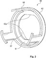
- the case 60 is formed by a flange-shaped bottom plate 61 having a mating hole 62 in the center, a rib 63 slightly extending in the axial direction from the bottom plate 61, and three guiding pieces 64 (guiding members) extending in the axial direction from the rib 63.
- the guiding pieces 64 are formed at equal intervals in a circumferential direction, and engage with notches 42 ( FIG. 1 ) which are formed similarly at equal intervals in the outer circumferential surface of the seal ring 40.
- the seal ring 40 becomes in a state movable in the axial direction of the rotating shaft 2 and in a state immovable in the circumferential direction (the rotating direction).
- the mating ring 30 is fitted into an annular recess 12 which is formed in expanded diameter in an opening, on the inside M of the compressor, of the shaft hole 11 of the housing 1 while interposing a gasket 50 therebetween.
- a metal ring 51 in the inside of the gasket 50 is covered with a rubber member 52 by insert molding.
- the rotating shaft 2 is formed with a large diameter portion 20, a first step 21, a second step 22, and a small diameter portion 23 from the inside M of the compressor.
- An outer surface (a right surface) of the bottom plate 61 abuts a radially extending surface of the first step 21 of the rotating shaft 2, thereby the case 60 is locked in the axial direction of the rotating shaft 2.
- the case 60 is configured such that flat parts 62a of the mating hole 62 engage with notches 26 formed in a part of the first step 21 of the rotating shaft 2 ( FIG. 1 ).
- the case 60 is mated with the rotating shaft 2 so as to rotate immovably in the circumferential direction with respect to the rotating shaft 2, that is, integrally with the rotating shaft 2 along with rotation of the rotating shaft 2.
- the second step 22 has a smaller diameter than that of the first step 21, and the seal ring 40 is attached thereto.
- the small diameter portion 23 has a smaller diameter than that of the second step 22 and is formed continuously to an inclined portion 22a, and the mating ring 30 is inserted therein and a tip part of the lip seal 90 (the auxiliary seal) contacts the outer circumferential surface thereof.
- the lip seal 90 is fitted into and fixed to an annular recess 13 which is formed in expanded diameter in an opening, on the atmosphere side A, of the shaft hole 11 of the housing 1.
- the lip seal 90 is mainly composed of a seal member 91, a metal ring 92, and a back-up ring 94.
- the seal member 91 and the back-up ring 94 are housed in and held by the metal ring 92 which is covered with a rubber member 93 by insert molding.
- the seal member 91 is formed of polytetrafluoroethylene (PTFE) as a main component.
- a biasing force by the spring 70 is given to the seal ring 40 in the axial direction of the rotating shaft 2, and the sliding surface 40a at a tip of the sliding protrusion 41 is pressed against the sliding surface 30a of the mating ring 30 under appropriate working pressure.
- the seal ring 40 is given a rotating torque from the rotating shaft 2 via the case 60, and rotates integrally with the rotating shaft 2.
- the sliding surface 30a of the mating ring 30 and the sliding surface 40a of the seal ring 40 slide in close contact state, and the refrigerant is sealed by sliding of the sliding surface 30a of the mating ring 30 and the sliding surface 40a of the seal ring 40.
- the intermediate chamber C is a chamber provided in the space on the atmosphere side A, and is defined by the small diameter portion 23 of the rotating shaft 2, the inclined portion 22a of the rotating shaft 2, the inner circumferential surface of the seal ring 40, the inner circumferential surface of the mating ring 30, the inner circumferential surface of the gasket 50, the inner circumferential surface of the housing 1 between the mechanical seal 3 and the lip seal 90, and a side surface of the lip seal 90.
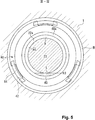
- the refrigerator oil L is stored to a height position (a position shown by a dashed line h0 in FIG. 1 and FIG. 3 ) of an approximate lower half of the annular sliding surface 40a, the refrigerator oil L is supplied between the sliding surface 30a and the sliding surface 40a, and poor lubrication is prevented.
- the sliding surface 30a and the sliding surface 40a are mirror finished, and a gap between the sliding surface 30a and the sliding surface 40a (a gap between the sliding surfaces) is very small, therefore, as shown by arrows in FIG. 4 , the refrigerator oil L in the intermediate chamber C is guided to the gap to the outer diameter side by capillary action.
- the refrigerator oil L is interposed in the gap (the gap between the sliding surfaces).
- the refrigerator oil is guided to the gap (the gap between the sliding surfaces) by a capillary action, and therefore it can be ensured that a lubricating film is interposed between the sliding surfaces.
- the refrigerator oil is supplied to a part of the lower part of the gap (the gap between the sliding surfaces), and the refrigerator oil is guided upward sequentially in the circumferential direction along with rotation (a white arrow in FIG. 4 ) of the seal ring 40 and supplied to the entire sliding surfaces.
- the mechanical seal 3 can maintain fluid lubrication and is superior in durability.
- the sliding surface 30a and the sliding surface 40a are respectively formed to have an arithmetic mean roughness Ra of 0.2 ⁇ m or less, preferably 0.1 ⁇ m or less, and thereby reducing the gap (the gap between the sliding surfaces).
- the refrigerator oil L is stored to a position higher than a position (a position shown by a dashed line h1 in FIG. 1 and FIG. 3 ) of a portion 45 of the sliding surface 40a which is located at the lowermost side in the intermediate chamber C.
- the height to which the refrigerator oil L is stored may be a position higher than a portion (a position shown by a dashed line h2 in FIG. 1 ) located at the lowermost side of the inner circumferential surface of the mating ring 30, or a position almost higher than a portion (a position shown by a dashed line h3 in FIG. 1 and FIG.
- FIG. 5 shows a modification in which the height to which the refrigerator oil L is stored is a position (a position shown by a dashed line h3 in FIG. 3 ) at the lowermost side of the outer circumferential surface of the small diameter portion 23 of the rotating shaft 2.
- the refrigerator oil L is stored so as to leave a space C1 where the refrigerator oil L does not exist on the upper side in the intermediate chamber C, and by leaving the space C1 on the upper side in the intermediate chamber C, even if the refrigerator oil L expands due to temperature change, pressure of the intermediate chamber C does not excessively rise because the space C1 serves as a buffer. Therefore, pressure of the intermediate chamber C does not excessively rise, and differential pressure between the inside M of the mechanical seal 3 and the intermediate chamber C is not largely fluctuated, and thereby capable of successfully sealing without significantly losing pressure balance acting on the mechanical seal 3.
- the seal member 91 is formed of polytetrafluoroethylene (PTFE) as a main component, and has low friction property, heat resistance property, and refrigerant permeability. Since the seal member 91 is formed of a material allowing the refrigerant to permeate therethrough, the refrigerant which is leaked to the intermediate chamber C through the gap between the sliding surfaces 30a, 40a of the mechanical seal 3 can permeate to the atmosphere side A. Thereby, since fluctuation of pressure of the intermediate chamber C is reduced, differential pressure between the inside M of the mechanical seal 3 and the intermediate chamber C is not largely fluctuated, and thereby capable of successfully sealing without significantly losing pressure balance acting on the mechanical seal 3. Similarly, fluctuation of differential pressure between the intermediate chamber C and the atmosphere side A can be reduced.
- PTFE polytetrafluoroethylene
- the seal member 91 may be formed of a material which seals the refrigerator oil L and allows to the gaseous refrigerant as a main component to permeate therethrough, and in addition to polytetrafluoroethylene, nitrile rubber, hydrogenated nitrile rubber, fluorine-containing rubber, ethylene-propylene-diene rubber, acrylic rubber, silicone rubber, and the like can be used.
- the height to which the refrigerator oil L is stored in the intermediate chamber C in other words, the amount of the refrigerator oil L stored in the intermediate chamber C may be in a range satisfying the aforementioned condition of supplying the refrigerator oil L between the sliding surfaces and the aforementioned condition of leaving the space C1 on the upper side in the intermediate chamber C. Then, in a stationary state, it is preferable that the refrigerator oil L is stored to a height position (a position shown by the dashed line h3 or higher and a dashed line h4 or lower in FIG. 1 and FIG. 3 ) where the rotating shaft 2 at the portion that the seal member 91 contacts, that is, a part of the small diameter portion 23 contacts the refrigerator oil L. According to this, these conditions can be surely satisfied, control of injection amount of the refrigerator oil L is facilitated, and assembly of the shaft seal device 10 is easy.
- the lip seal 90 is adopted as the auxiliary seal, miniaturization is possible compared to the case of adopting the mechanical seal and the like. Moreover, the lip seal 90 is preferable if the seal member 91 is a so-called single seal because refrigerant permeability can be ensured.
- the lip seal 90 is arranged on the atmosphere side A than the mechanical seal 3, the mechanical seal 3 serves as a main seal, and thereby shaft seal of the refrigerant of high pressure is ensured.
- the intermediate chamber C extends to the atmosphere side A, the refrigerator oil L in the intermediate chamber C is cooled from the atmosphere side A and contributes to the cooling of the mating ring 30 and the seal ring 40.
- the refrigerator oil L has a few portions in contact with the members on the rotating side, and rotating torque of the rotating shaft 2 is less affected.
- the mechanical seal 3 since the mechanical seal 3 is used, shaft seal of carbon dioxide which is the refrigerant of high pressure is ensured. Further, since the refrigerator oil L in the intermediate chamber C is supplied between the sliding surfaces even if the refrigerator oil L between the sliding surfaces is dissolved into the liquefied refrigerant, a lubricating film can be formed, and the mechanical seal 3 is superior in durability.
- the second embodiment is mainly different from the first embodiment in a position where a lip seal 190 is provided. It should be noted that descriptions of the configuration similar to the first embodiment will be omitted.
- the lip seal 190 (the auxiliary seal) is arranged on the inside M of the compressor than the mechanical seal 3.
- An intermediate chamber D between the lip seal 190 and the mechanical seal 3 is a chamber provided in the space on the inside M of the compressor, and, in the intermediate chamber D, the refrigerator oil L is stored to a height position of an approximate lower half of the annular sliding surface 40a so as to leave a space D1 on the upper side.
- the lip seal 190 is mainly composed of a seal member 191, a back-up ring 194, and a metal ring 192.
- the seal member 191 and the back-up ring 194 are housed in and held by the metal ring 192 which is covered with a rubber member 193 by insert molding.
- the seal member 191 is formed of polytetrafluoroethylene (PTFE) as a main component.
- PTFE polytetrafluoroethylene
- a tip part of the lip seal 190 contacts the outer circumferential surface of the large diameter portion 20 of the rotating shaft 2.
- the lip seal 190 is fitted from the opening, on the inside M of the compressor, of the shaft hole 11 of the housing 1, and its axial position is restricted by a snap ring 195.
- the refrigerator oil L is stored to a height position of an approximate lower half of the annular sliding surface 40a, the refrigerator oil L is supplied between the sliding surface 30a and the sliding surface 40a, and poor lubrication is prevented.
- the above-mentioned embodiments describe the case of the rotating mechanical seal 3, but it may be a stationary mechanical seal 3.
- the refrigerator oil which is stored in the intermediate chambers C and D is same as the refrigerator oil sealed in the refrigeration cycle device is described as an example, but the kinds of the refrigerator oil may be different.
- both the mating ring 30 and the seal ring 40 may be formed of hard sliding material (for example, ceramics such as SiC).
Landscapes
- Engineering & Computer Science (AREA)
- General Engineering & Computer Science (AREA)
- Mechanical Engineering (AREA)
- Compressor (AREA)
- Sealing With Elastic Sealing Lips (AREA)
- Mechanical Sealing (AREA)
- Sealing Devices (AREA)
Applications Claiming Priority (1)
| Application Number | Priority Date | Filing Date | Title |
|---|---|---|---|
| JP2016213464A JP2018071702A (ja) | 2016-10-31 | 2016-10-31 | 冷凍機コンプレッサの軸封装置 |
Publications (1)
| Publication Number | Publication Date |
|---|---|
| EP3315833A1 true EP3315833A1 (fr) | 2018-05-02 |
Family
ID=60201379
Family Applications (1)
| Application Number | Title | Priority Date | Filing Date |
|---|---|---|---|
| EP17199087.2A Withdrawn EP3315833A1 (fr) | 2016-10-31 | 2017-10-30 | Dispositif d'étanchéité de compresseur de réfrigérateur |
Country Status (2)
| Country | Link |
|---|---|
| EP (1) | EP3315833A1 (fr) |
| JP (1) | JP2018071702A (fr) |
Cited By (1)
| Publication number | Priority date | Publication date | Assignee | Title |
|---|---|---|---|---|
| CN113904478A (zh) * | 2021-09-28 | 2022-01-07 | 珠海格力节能环保制冷技术研究中心有限公司 | 一种电机组件、压缩机及空调器 |
Families Citing this family (2)
| Publication number | Priority date | Publication date | Assignee | Title |
|---|---|---|---|---|
| JP7234073B2 (ja) * | 2019-08-09 | 2023-03-07 | イーグル工業株式会社 | ダブル型メカニカルシール |
| CN112664654B (zh) * | 2020-12-30 | 2024-09-10 | 清华大学 | 可监测磨损量的机械密封装置 |
Citations (6)
| Publication number | Priority date | Publication date | Assignee | Title |
|---|---|---|---|---|
| JPS571953U (fr) * | 1980-06-04 | 1982-01-07 | ||
| GB2217396A (en) * | 1988-04-12 | 1989-10-25 | Flexibox Ltd | Tandem shaft seal |
| US5692756A (en) * | 1995-09-22 | 1997-12-02 | Rexnord Corporation | Refrigeration compressor and compressor seal |
| JPH11344126A (ja) * | 1998-05-29 | 1999-12-14 | Eagle Ind Co Ltd | 冷凍機コンプレッサ用軸封装置 |
| US20020074728A1 (en) * | 2000-11-13 | 2002-06-20 | Reinhold Kraus | Rotating mechanical seal |
| JP2007009886A (ja) | 2005-07-04 | 2007-01-18 | Toyota Industries Corp | 圧縮機 |
Family Cites Families (9)
| Publication number | Priority date | Publication date | Assignee | Title |
|---|---|---|---|---|
| EP0580400B1 (fr) * | 1992-07-21 | 1996-08-21 | Cummins Engine Company, Inc. | Joint pour pompe à eau auto-étanchéifiant |
| JP2000136881A (ja) * | 1998-11-04 | 2000-05-16 | Eagle Ind Co Ltd | 高圧ガス圧縮機用軸シール装置 |
| JP4094176B2 (ja) * | 1999-07-13 | 2008-06-04 | イーグル工業株式会社 | メカニカルシール |
| JP2007223890A (ja) * | 2006-01-30 | 2007-09-06 | Kyocera Corp | 炭化けい素質焼結体とこれを用いた摺動部材およびメカニカルシールリング、並びにメカニカルシール |
| DE102007050349B4 (de) * | 2007-10-11 | 2018-06-07 | Kaco Gmbh + Co. Kg | Dichtungsanordnung für den Hochdruckbereich |
| US9388905B2 (en) * | 2009-09-24 | 2016-07-12 | Eagle Industry Co., Ltd. | Mechanical seal |
| JP5123371B2 (ja) * | 2010-12-24 | 2013-01-23 | 株式会社神戸製鋼所 | メカニカルシール |
| WO2014168112A1 (fr) * | 2013-04-09 | 2014-10-16 | イーグル工業株式会社 | Élément d'étanchéité glissant |
| JP6490994B2 (ja) * | 2015-03-09 | 2019-03-27 | 日本ピラー工業株式会社 | 多流路形ロータリジョイント |
-
2016
- 2016-10-31 JP JP2016213464A patent/JP2018071702A/ja active Pending
-
2017
- 2017-10-30 EP EP17199087.2A patent/EP3315833A1/fr not_active Withdrawn
Patent Citations (6)
| Publication number | Priority date | Publication date | Assignee | Title |
|---|---|---|---|---|
| JPS571953U (fr) * | 1980-06-04 | 1982-01-07 | ||
| GB2217396A (en) * | 1988-04-12 | 1989-10-25 | Flexibox Ltd | Tandem shaft seal |
| US5692756A (en) * | 1995-09-22 | 1997-12-02 | Rexnord Corporation | Refrigeration compressor and compressor seal |
| JPH11344126A (ja) * | 1998-05-29 | 1999-12-14 | Eagle Ind Co Ltd | 冷凍機コンプレッサ用軸封装置 |
| US20020074728A1 (en) * | 2000-11-13 | 2002-06-20 | Reinhold Kraus | Rotating mechanical seal |
| JP2007009886A (ja) | 2005-07-04 | 2007-01-18 | Toyota Industries Corp | 圧縮機 |
Cited By (1)
| Publication number | Priority date | Publication date | Assignee | Title |
|---|---|---|---|---|
| CN113904478A (zh) * | 2021-09-28 | 2022-01-07 | 珠海格力节能环保制冷技术研究中心有限公司 | 一种电机组件、压缩机及空调器 |
Also Published As
| Publication number | Publication date |
|---|---|
| JP2018071702A (ja) | 2018-05-10 |
Similar Documents
| Publication | Publication Date | Title |
|---|---|---|
| JP5580532B2 (ja) | メカニカルシール装置 | |
| US9309973B2 (en) | Sealing device and sealing structure | |
| KR102180853B1 (ko) | 레이디얼 샤프트 시일 | |
| EP3315833A1 (fr) | Dispositif d'étanchéité de compresseur de réfrigérateur | |
| US6290470B1 (en) | Shaft sealing assembly and compressor incorporating the same | |
| EP2000712A9 (fr) | Système de joint pour arbre de machine hydraulique | |
| US20120235361A1 (en) | Sealing Device | |
| JP5801033B2 (ja) | シール構造 | |
| US8197346B2 (en) | Shuttle vent valve | |
| EP3276173A1 (fr) | Joint d'arbre de réfrigérant et compresseur de réfrigérant ouvert équipé d'un joint d'arbre de réfrigérant | |
| WO2016103601A1 (fr) | Dispositif d'étanchéité d'arbre et compresseur utilisant celui-ci | |
| US6688602B2 (en) | Shaft sealing mechanism of compressor with mechanical seal | |
| JP5807095B2 (ja) | シールリング及びシール装置 | |
| EP3742027A1 (fr) | Structure d'étanchéité et joint d'étanchéité à utiliser dans celle-ci | |
| JP2009024541A (ja) | 軸シール | |
| JP2001004034A (ja) | Co2圧縮機用メカニカルシール | |
| JPH09133217A (ja) | リップ型シール | |
| EP2123953B1 (fr) | Dispositif de joint pour arbre | |
| US11047388B2 (en) | Single-screw compressor | |
| JP2017150590A (ja) | 密封装置 | |
| JP2009257131A (ja) | 圧縮機の潤滑剤供給構造 | |
| JP4845643B2 (ja) | シール装置 | |
| JPWO2014156819A1 (ja) | シール装置 | |
| JP2004332829A (ja) | 軸封構造 | |
| JP2008286082A (ja) | ポンプ |
Legal Events
| Date | Code | Title | Description |
|---|---|---|---|
| PUAI | Public reference made under article 153(3) epc to a published international application that has entered the european phase |
Free format text: ORIGINAL CODE: 0009012 |
|
| STAA | Information on the status of an ep patent application or granted ep patent |
Free format text: STATUS: THE APPLICATION HAS BEEN PUBLISHED |
|
| AK | Designated contracting states |
Kind code of ref document: A1 Designated state(s): AL AT BE BG CH CY CZ DE DK EE ES FI FR GB GR HR HU IE IS IT LI LT LU LV MC MK MT NL NO PL PT RO RS SE SI SK SM TR |
|
| AX | Request for extension of the european patent |
Extension state: BA ME |
|
| STAA | Information on the status of an ep patent application or granted ep patent |
Free format text: STATUS: REQUEST FOR EXAMINATION WAS MADE |
|
| 17P | Request for examination filed |
Effective date: 20180614 |
|
| RBV | Designated contracting states (corrected) |
Designated state(s): AL AT BE BG CH CY CZ DE DK EE ES FI FR GB GR HR HU IE IS IT LI LT LU LV MC MK MT NL NO PL PT RO RS SE SI SK SM TR |
|
| STAA | Information on the status of an ep patent application or granted ep patent |
Free format text: STATUS: EXAMINATION IS IN PROGRESS |
|
| 17Q | First examination report despatched |
Effective date: 20200408 |
|
| STAA | Information on the status of an ep patent application or granted ep patent |
Free format text: STATUS: THE APPLICATION IS DEEMED TO BE WITHDRAWN |
|
| 18D | Application deemed to be withdrawn |
Effective date: 20200819 |