EP3316477A1 - Procédé de simulation d'un moteur électrique triphasé à l'aide d'un émulateur de charge et émulateur de charge correspondant - Google Patents
Procédé de simulation d'un moteur électrique triphasé à l'aide d'un émulateur de charge et émulateur de charge correspondant Download PDFInfo
- Publication number
- EP3316477A1 EP3316477A1 EP16195987.9A EP16195987A EP3316477A1 EP 3316477 A1 EP3316477 A1 EP 3316477A1 EP 16195987 A EP16195987 A EP 16195987A EP 3316477 A1 EP3316477 A1 EP 3316477A1
- Authority
- EP
- European Patent Office
- Prior art keywords
- emulator
- motor
- control
- power electronics
- supply
- Prior art date
- Legal status (The legal status is an assumption and is not a legal conclusion. Google has not performed a legal analysis and makes no representation as to the accuracy of the status listed.)
- Granted
Links
Images


Classifications
-
- H—ELECTRICITY
- H02—GENERATION; CONVERSION OR DISTRIBUTION OF ELECTRIC POWER
- H02P—CONTROL OR REGULATION OF ELECTRIC MOTORS, ELECTRIC GENERATORS OR DYNAMO-ELECTRIC CONVERTERS; CONTROLLING TRANSFORMERS, REACTORS OR CHOKE COILS
- H02P27/00—Arrangements or methods for the control of AC motors characterised by the kind of supply voltage
- H02P27/04—Arrangements or methods for the control of AC motors characterised by the kind of supply voltage using variable-frequency supply voltage, e.g. inverter or converter supply voltage
- H02P27/06—Arrangements or methods for the control of AC motors characterised by the kind of supply voltage using variable-frequency supply voltage, e.g. inverter or converter supply voltage using DC to AC converters or inverters
- H02P27/08—Arrangements or methods for the control of AC motors characterised by the kind of supply voltage using variable-frequency supply voltage, e.g. inverter or converter supply voltage using DC to AC converters or inverters with pulse width modulation
-
- G—PHYSICS
- G01—MEASURING; TESTING
- G01R—MEASURING ELECTRIC VARIABLES; MEASURING MAGNETIC VARIABLES
- G01R31/00—Arrangements for testing electric properties; Arrangements for locating electric faults; Arrangements for electrical testing characterised by what is being tested not provided for elsewhere
- G01R31/40—Testing power supplies
- G01R31/42—AC power supplies
-
- G—PHYSICS
- G05—CONTROLLING; REGULATING
- G05B—CONTROL OR REGULATING SYSTEMS IN GENERAL; FUNCTIONAL ELEMENTS OF SUCH SYSTEMS; MONITORING OR TESTING ARRANGEMENTS FOR SUCH SYSTEMS OR ELEMENTS
- G05B17/00—Systems involving the use of models or simulators of said systems
- G05B17/02—Systems involving the use of models or simulators of said systems electric
-
- H—ELECTRICITY
- H02—GENERATION; CONVERSION OR DISTRIBUTION OF ELECTRIC POWER
- H02P—CONTROL OR REGULATION OF ELECTRIC MOTORS, ELECTRIC GENERATORS OR DYNAMO-ELECTRIC CONVERTERS; CONTROLLING TRANSFORMERS, REACTORS OR CHOKE COILS
- H02P27/00—Arrangements or methods for the control of AC motors characterised by the kind of supply voltage
- H02P27/04—Arrangements or methods for the control of AC motors characterised by the kind of supply voltage using variable-frequency supply voltage, e.g. inverter or converter supply voltage
- H02P27/06—Arrangements or methods for the control of AC motors characterised by the kind of supply voltage using variable-frequency supply voltage, e.g. inverter or converter supply voltage using DC to AC converters or inverters
-
- H—ELECTRICITY
- H02—GENERATION; CONVERSION OR DISTRIBUTION OF ELECTRIC POWER
- H02P—CONTROL OR REGULATION OF ELECTRIC MOTORS, ELECTRIC GENERATORS OR DYNAMO-ELECTRIC CONVERTERS; CONTROLLING TRANSFORMERS, REACTORS OR CHOKE COILS
- H02P6/00—Arrangements for controlling synchronous motors or other dynamo-electric motors using electronic commutation dependent on the rotor position; Electronic commutators therefor
- H02P6/34—Modelling or simulation for control purposes
-
- H—ELECTRICITY
- H02—GENERATION; CONVERSION OR DISTRIBUTION OF ELECTRIC POWER
- H02P—CONTROL OR REGULATION OF ELECTRIC MOTORS, ELECTRIC GENERATORS OR DYNAMO-ELECTRIC CONVERTERS; CONTROLLING TRANSFORMERS, REACTORS OR CHOKE COILS
- H02P7/00—Arrangements for regulating or controlling the speed or torque of electric DC motors
- H02P7/06—Arrangements for regulating or controlling the speed or torque of electric DC motors for regulating or controlling an individual DC dynamo-electric motor by varying field or armature current
Definitions
- the invention relates to a method for simulating a three-phase electric motor with a load emulator, wherein the load emulator is connected in three phases via its load terminals to the supply terminals of a motor controller and the load emulator has an emulator power electronics and an emulator control for controlling the emulator power electronics, wherein the emulator control controlled by the engine control Detected supply terminals and non-driven supply terminals, and the emulator power electronics is controlled by the emulator controller so that in the controlled by the engine control input terminals of the emulator controller based on a motor model calculated phase currents i emulate flow and on the non-controlled by the engine control supply terminal one of the emulator control is calculated based on a motor model phase voltage v emulate .
- the invention also relates to the emulator control of a load emulator configured to perform the previously described method of simulating a three-phase electric motor in conjunction with emulator power electronics.
- the inverter of the motor controller works as an inverter, so it has as a source of energy to a DC voltage source and drives a load with AC voltage.
- the inverter of the motor control usually comprises a realized with said circuit breakers half-bridge circuit, wherein the circuit breakers are provided with antiparallel-connected freewheeling diodes, can be reduced by the inductances of the motor driven currents with open circuit breaker.
- the load emulator is often realized in the form of a hardware-in-the-loop simulator, ie by a simulation computer, the mathematical models of the environment to be simulated - here the load in the form of three-phase electric motor - calculated by numerical methods and in turn via a power electronic power amplifier - the emulator power electronics - has, which can be connected via the load terminals of the load emulator with the corresponding supply terminals of the engine control.
- the process implemented on the load emulator to simulate a three-phase electric motor causes the motor controller to be electrically charged via its supply terminals as if it were connected to the real drive.
- a method described above for simulating a three-phase electric motor for example, from EP 2940857 A1 known.
- the three-phase electric motor is exclusively a brushless DC motor.
- the disclosure of this application is referred to because of their contentual proximity.
- Brushless DC motors are low wear and maintenance due to the brushless design.
- the emulator power electronics includes for acting on the supply terminals of the motor controller with corresponding electrical connection values voltage sources and power sources, which are usually connectable via decoupling inductances with the load terminals of the emulator power electronics.
- voltage sources and power sources which are usually connectable via decoupling inductances with the load terminals of the emulator power electronics.
- the EP 2940857 A1 describes a method that allows a high quality replica of a three-phase brushless DC motor with a load emulator by reliably timing commutation is recognized even under changing operating conditions. This concerns the normal operation of the three-phase DC motor.
- the object of the present invention is therefore to further develop the method described above for simulating a three-phase electric motor with a load emulator so that it does not affect the operation of brushless Three-phase DC motors is limited and also takes into account special operating situations of a three-phase electric motor, which are beyond the motor or generator normal operation.
- the load emulator comprises a switching means with which the emulator power electronics can be switched off from the supply connections with high impedance and with which the emulator power electronics can be switched to the supply connections with low resistance , and wherein the supply terminals are interconnected via a high resistance network.
- the emulator power electronics with the switching means is separated from the high-impedance feed terminals for simulation of selected operating conditions of the electric motor or the already isolated with high impedance from the supply terminals emulator power electronics with the circuit means low impedance connected to the supply terminals.
- the load emulator is supplemented by circuitry by a switching means and by a high-impedance resistance network.
- the switching means allows the emulator power electronics to be switched off from the supply connections in a high-impedance manner and, of course, conversely, the emulator power electronics can be connected to the supply connections at low impedance again.
- This "separation" can be realized by various circuit engineering measures. It is not necessary that a complete galvanic decoupling is present, it is also sufficient if a very high-impedance electrical separation of the emulator power electronics from the supply connections is possible, for example by semiconductor switches which do not represent perfect galvanic isolation.
- the proposed switching means it is thus possible to prevent an interaction between the motor control and the emulator power electronics, which is advantageous in some situations, as will be shown below.
- the supply connections are connected via a high-resistance network.
- This connection of the supply connections The high-resistance resistor network is not affected by the switching means, so the high-impedance resistor network is also connected to the supply terminals when the emulator power electronics with the switching means is switched off high impedance from the supply terminals.
- the high-impedance connection of the supply connections via the resistor network is selected in such a way that during normal operation of the load emulator, ie when there is a functioning low-resistance connection between the emulator power electronics and the supply connections, the motor control system only insignificantly loads the motor control.
- the purpose of the resistor network is that the supply terminals of the motor controller, which are indeed connected to the load terminals of the load emulator, are also connected when the emulator power electronics has been switched off with high impedance to the switching means of the load terminals or from the supply terminals.
- the supply terminals of the motor control are then not electrically open, but connected to each other via the high-impedance resistor network.
- circuitry is the prerequisite created that can be reacted to certain modes of engine control in principle, even if the emulator power electronics is separated from the engine control high impedance.
- This is desirable, for example, when the motor controller in an initialization phase, a voltage on the supply terminals or a voltage pattern on different supply terminals and tries to measure back via the other supply terminals, a voltage so as to obtain information about the seemingly connected engine.
- such feedback via the high-impedance resistor network is readily possible.
- the high-impedance resistor network therefore represents the motor connected to the motor control, even if the emulator power electronics have been switched off from the supply connections with high resistance.
- the emulator power electronics are thus separated from the supply connections with high impedance by the switching means.
- the method for simulating a three-phase electric motor with a load emulator is preferably designed such that a star circuit of three substantially ohmic resistors is selected as the high-resistance resistor network, each of the free ends of the star connection being connected to a different supply connection of the motor control.
- the symmetrical star connection also simulates the symmetrically configured phases of the three-phase electric motor to be emulated.
- the star point is potential-free, so it sets here the potential that results from the appropriate voltage control of the free ends of the star connection through the supply terminals of the motor control, in any case, this is the determining influence when the emulator power electronics is separated from the high-impedance feed terminals ,
- the motor control does not control a feed connection and the emulator power electronics with the switching means is separated from the load connections with high resistance, that a motorized motor start is detected by an incipient activation of the supply connections by the motor control, if at least one of the between the supply terminals i , j of the motor control by measurement determined output differential voltages v inv, diff (i, j) is greater than a predetermined voltage threshold TH impedance .
- the motor is driven by a motor out of a standstill so that voltages are supplied via the power output stage of the motor control system to energize the three-phase electric motor via the supply connections.
- These output voltages v inv are then pulled either to the intermediate circuit voltage v DC_Link or to the ground potential.
- a certain voltage threshold TH impedance is specified.
- the regenerative case can also be detected, that is, if the simulated three-phase electric motor is driven by a load.
- the engine control system does not control a feed connection and the emulator power electronics with the switching means are separated from the load connections with high resistance, and that a regenerative motor start is detected when the engine speed of the engine model is evaluated and the engine speed is not equal to zero.
- the simulated rotational speed is evaluated; an actual speed is of course not present, since the three-phase electric motor is emulated in the emulator control only. As soon as the simulated electric motor rotates, all phases are changed to the activated state, for example by applying a voltage to the load connections (voltage mode).
- the emulator control activates the load terminals of the emulator power electronics so that the test connections are supplied with a test voltage which can not be applied to the supply connections by the motor control, in particular if the test voltage is half the DC link voltage v DC_Link the engine control corresponds.
- test voltage v DC_Link / 2 plus the simulated induced countervoltages in the corresponding motor phase is used as the voltage setpoint. Then the test voltage is merely an offset for the emulated induced phase voltages. When the motor is in an initial state, the induced countervoltages are equal to zero. However, if the motor is operated as a generator with open bridge switches or if the motor is spinning when the bridge switches are open, there is an induced reverse voltage, which is then also taken into account with the setpoint.
- the choice of a test voltage, which can not be generated by the motor control, serves to distinguish the returned voltage potentials.
- the motor controller can connect to the supply terminals by means of acting in their half-bridge switch only the DC link voltage or the ground potential, so half the DC link voltage can not come from the engine control, it is when this voltage is measured on a phase, so to a not controlled by the engine control phase, which is enabled via open half-bridge switch potential.
- This measure serves to decay transient processes in the load emulator, in particular in the emulator power electronics, so that a stable and reliable value is obtained in the evaluation of the voltages.
- the latency t 3 is at least as long as the emulator power electronics required to reliably set the specification of the test voltage.
- the method presented here for simulating a three-phase electric motor is not limited to block-commutated electric motors, but rather also electric motors can be simulated, in which all phases are controlled without interruption, so be charged with a calculated current through the emulator power electronics.
- a further development of the method therefore provides that it is reliably detected for any phase of the motor and therefore for any desired supply connection of the motor control system whether the phase or the feed connection is actuated further by the motor control or not. This question arises at each zero crossing of the current in one phase. With sinusoidal control, each phase remains in the driven state, even with a zero crossing of the current, whereas with block-commutated control at a zero crossing of the current always one of the previously activated phases changes to the non-driven state.
- time integral V integral, 1 is greater than a predefined voltage time threshold value V Diode TH, 1 (k) , then the considered phase has changed to the non-activated state. This has the consequence that the identified as not controlled phase or the corresponding load connection changes from the emulator power electronics of the current in the voltage mode, that is no longer charged with a calculated current, but with a calculated induction voltage, since the phase is enabled by the motor control, so floating.
- a refinement of the method based thereon is characterized in that the predetermined first current value i emulate, 1 (k) is less than half the maximum calculated current value of the phase current i emulate, (k) , in particular less than one quarter of the maximum calculated current value of the phase current i emulate, (k). this ensures that the current actually moves to a zero crossing. For example, for a 100 A system, i emulate , (k) should be less than 25 amps. In practice, a useful threshold could be chosen between 1A and 2A for 100 A systems. For applications in the small power range (eg hard disk motors), this threshold can also be significantly smaller. It is important that the voltage across the freewheeling diodes is still clearly measurable in the defined current band before the current has completely dissipated.
- the predetermined second current value i emulate, 2 (k) is a fraction of the predetermined first current value i emulate, 1 (k) , preferably three quarters of the predetermined first current value i emulate, 1 (k) .
- the predetermined second current value i emulate, 2 (k) should in any case be chosen so large that the voltage across the freewheeling diodes can not completely break down.
- the predetermined voltage time threshold V diode TH , 1 (k) the time integral of the half free-wheeling diode voltage one included by the engine control freewheeling diode is.
- 1 1 (k) the time interval TI Vcalc, 1 1 (k) is here used, in which the value calculated by the emulator control phase current emulate emulate (k) of the predetermined first current value i i, emulate to the predetermined second current value i, 2 (k) drops.
- the resulting threshold value is sufficiently large to distinguish from such an integrated voltage, which may still be present at the controlled supply connection, when the supply connection is pulled to the zero potential or to the high potential via a circuit breaker of the motor control converter.
- the load emulator is connected in three phases via its load terminals to the supply terminals of a motor controller and the load emulator has an emulator power electronics and an emulator control for controlling the emulator power electronics
- said the emulator controller detects the motorized control and non-driven supply pins and the emulator power electronics through the emulator controller is controlled such that in the motor control-driven feed terminals emulator control based on a motor model calculated phase currents i emulate flow and is applied to the not controlled by the engine control supply terminal emulated by the emulator control based on a motor model phase voltage v emulate
- the load emulator comprises a switching means with which the emulator power electronics can be switched off in a high-impedance manner from the supply connections and with which the emulator power electronics can be switched to the supply connections in a low-impedance manner and wherein the supply connections are connected to one another via a high-resistance network.
- the load emulator is characterized on the basis of the method described above in that the emulator control to simulate selected operating conditions of the electric motor, the emulator power electronics and the switching means controls so that the emulator power electronics with the switching means high impedance is disconnected from the supply terminals or already with high impedance of the emulator power electronics separated with the supply terminals is connected to the switching means with low impedance to the supply terminals.
- the high-impedance resistor network is a star connection of three substantially ohmic resistors, each of the free ends of the star connection being connected to a respective different supply connection of the motor control.
- the emulator control is designed such that, when used as intended, it carries out the above-described method for simulating a three-phase electric motor with the load emulator.
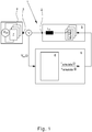
- Fig. 1 is initially shown a known from the prior art arrangement for carrying out a method for simulating a three-phase electric motor, which is in the art limiting a brushless DC motor.
- the arrangement initially has a load emulator 1, wherein the load emulator 1 is connected in three phases via its load terminals 2 to the supply terminals 3 of a motor control 4.
- the load emulator 1 has an emulator power electronics 5 and an emulator control 6 for controlling the emulator power electronics 5.
- the motor controller 4 itself also includes power electronics in the form of a three-phase inverter 7, which is supplied with power via a DC voltage source V DC and drives a three-phase alternating load through its supply terminals 3 by appropriate switching of the semiconductor switch encompassed by the inverter 7.
- the method provides that the emulator control 6 determines the driven by the motor controller 4 supply terminals 3 and non-driven supply terminals 3, wherein the emulator power electronics 5 is controlled by the emulator controller 6 so that in the driven by the motor controller 4 supply terminals 3 of the emulator controller. 6 based on a motor model 8 calculated phase currents i emulate flow and a phase voltage v emulate calculated by the emulator control 6 on the basis of the motor model 8 is applied to the supply connection 3 which is not controlled by the motor control 4. It can be seen that the emulator power electronics 5 to accomplish this task both current sources I s and voltage sources U S , which can be switched according to the load terminals 2 of the emulator power electronics 5, which in the present case indirectly for each phase via a decoupling inductance L. d takes place.
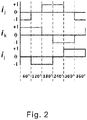
- Fig. 2 the six occurring within an electrical rotation commutation transitions in a three-phase block-commutated brushless DC motor are shown, wherein the commutations are carried out in each case at an electrical angular distance of 60 °. It can be seen that the uncontrolled feed connection is maintained only in one commutation interval in one phase and then immediately reverts to the activated state; the phases are designated here by i 1 , i 2 and i 3 . "Uncontrolled” here means that the respective supply connection of the motor control is open in terms of potential, ie neither by the circuit breaker of the inverter 7 to ground nor the positive operating voltage V DC is pulled.
- Trocketed is a phase or the associated feed connection 3 when the supply connection from the motor control is set to a defined electrical potential and is not open to potential - ie not floating.
- a supply connection changes to the non-activated state, while the other controlled supply connection remains in the activated state.
- a corresponding rotating field is generated in the brushless DC motor with which then a corresponding torque can be applied.
- a controller 9 is shown, which ensures that the predetermined phase currents are actually set at the load terminals 2 according to the specification from the emulator control 6. For this purpose, the respectively interesting phase current is measured back within the emulator power electronics 5 and fed to a control algorithm 10 for the purpose of forming a control difference.
- a modulator 11 assigns a predetermined voltage value or a predetermined current value to the respectively correct phase.
- the emulator control 6 is implemented in the illustrated embodiment on an FPGA board, on the "hard-wired" circuit structures ensure a particularly fast feasibility of the method described below.
- the output voltages v inv (j) which are measured at the supply terminals 3 of the motor controller 4, are read into the emulator control 6 and made available there, so they are genuine measured quantities.
- the calculated target values for calculated phase voltages v emulate (j) and for calculated phase currents i emulate (j) are output to the emulator power electronics 5 via the output interface 13.
- a state machine 14 is realized, with which commutation-related state changes at the supply connections 3 of the motor control 4 are detected.
- the state of the feed connection j is hereinafter referred to basically as S PH (j) , where the value 1 stands for the non-activated state of the supply connection j and the value 0 for the controlled state of the relevant supply connection. It can also flow in a non-driven supply terminal, a current over freewheeling diode until it comes to a halt. In this case, the state is 0.
- S PH (j) The detailed structure and content of the emulator control 6 is not relevant here in detail, this information is contained in the European published patent application EP 2940857 A1 ,
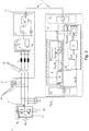
- the in Fig. 3 Load emulator 1 shown further comprises a switching means 15, with which the emulator power electronics 5 can be switched off from the supply terminals 3 with high resistance. It could just as well be said that with the switching means 15, the emulator power electronics can be switched off from the load terminals 2 with high resistance, which is ultimately also a factor Turning off the emulator power electronics 5 of the supply terminals 3 causes. It is important that the emulator power electronics 5 is no longer effectively connected to the motor controller 4 and can not act on the motor controller 4 electrically.
- the switching means 15 here comprises a total of three semiconductor switches, with which each phase can be separated from the load terminals 2 - and thus from the supply terminals 3 of the motor controller 4 - separately, with high resistance. In the case of the "high-resistance state" of a supply connection j which can be achieved by the switching means 15, S PH (j) assumes the value 2 in the following.
- the emulator power electronics 5 with the switching means 15 of course also low impedance back to the supply terminals 3 of the motor controller 4 are switched on.
- the low-resistance connection to the supply terminals 3 of the motor controller 4 is crucial, since it is about the electrically effective coupling of the emulator power electronics 5 to the motor controller 4.
- the load terminals 2 are connected to each other via a high-impedance resistor network 16. This is equivalent to the fact that the supply terminals 3 of the motor control via the high-impedance resistor network 16 are interconnected.
- the emulator power electronics 5 are separated from the load terminals 2 with high-resistance switching means 15 or the emulator power electronics 5 already disconnected from the load terminals 2 are switched to the load terminals 2 with the switching means 15 in a low-impedance manner. It could just as well mean that in order to simulate selected operating states of the electric motor, the emulator power electronics 5 are separated from the supply connections 3 with high-impedance switching means 15 or the emulator power electronics, which have already been separated from the supply connections 3 with high resistance, are switched to the supply connections 3 with the switching means 15 in a low-impedance manner. As a result, it is in any case the case that the switching means 15 does not influence the high-resistance connection of the supply connections 3 through the high-resistance resistor network 16.
- the high-impedance resistor network 16 is a star connection of three substantially ohmic resistors, each of the free ends of the star connection being connected to a respective different supply terminal 3 of the motor control 4.
- the resistors are substantially ohmic, it is meant that the elements of the resistor network 16 are resistors in the practical professional electrical engineering understanding, knowing that there are no ideal ohmic resistances, that is Of course, each electrical component may also have parasitic inductive and capacitive properties.
- a motor motor start is detected by the motor controller 4 by an incipient control of the supply terminals 3, if at least one of the feed terminals i, j of the motor controller 4 determined by measurement output differential voltages v inv , diff (i, j) is greater than a predetermined voltage threshold TH imepdance .
- measured differential voltages v inv, diff (i, j) between the supply terminals 3 of the motor control 4 can indicate an incipient activation of the motor.
- a regenerative motor start of the motor can also be detected. Again, the initial state is that the motor controller 4 does not drive a supply terminal 3 and the emulator power electronics 5 with the switching means 15 from the supply terminals 3 the motor control or from the load terminals 2 of the emulator power electronics 5 is separated.
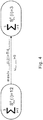
- a regenerative motor start is detected when the engine speed ⁇ mot, emu of the engine model 8 is evaluated and the engine speed ⁇ mot, emu is not equal to zero, which is also in Fig. 4 is shown.
- the result of the - motor or generator - detected motor start is that the emulator power electronics 5 with the switching means 15 low impedance to the load terminals 2 - and thus to the supply terminals 3 - is switched on and the emulator controller 6, the load terminals 2 of the emulator power electronics 5 so controls that the Load terminals 2 and thus the supply terminals 3 are subjected to a voltage, all phases of the emulator power electronics 5 thus operate in voltage mode.
- a test voltage is used which can not be applied to the load terminals 2 by the motor control 4 via the supply terminals 3, the test voltage here being half the DC link voltage v DC_Link of the motor control 4 corresponds.
- test voltage makes it possible to find out which of the supply terminals 3 are driven by the motor controller 4. If a supply connection 3 remains open-floating from the motor control 4, the test voltage applied by the emulator power electronics 5 can be measured back by the emulator control 6. Otherwise, the voltage applied by the motor controller 4 would be the relevant voltage and fed back via the supply connections 3 from the emulator control 6.
- the loading of the load terminals 2 with the test voltage is carried out over a latency t 3 .
- the latency t 3 is at least as long as the emulator power electronics 5 needed to reliably set the specification of the test voltage.
- the emulator control 6 controls the emulator power electronics 5 in such a way that via the motor control 4 driven feed terminal j, the phase current i emulate (j) calculated by the emulator control 6 flows.
- the control by the motor controller 4 is block commutated, and upon detection of three simultaneously controlled supply terminals 3, it can be assumed that a sinusoidal commutation is effected by the motor controller 4.
- a criterion must be found that allows a reliable and unambiguous evaluation of suitable state variables. It is not sufficient, for example, to simply observe zero crossings of the current in individual phases, since such current zero crossings are also present in sinusoidal-commutated motors which are continuously driven in all phases.
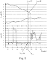
- Fig. 5 are initially shown the courses of two phase voltages and two phase currents, the course of the third phase voltage and the course of the third phase current have been omitted for reasons of clarity.
- the measured curve of the two phase voltages v inv is plotted in volts
- the corresponding calculated phase currents i emulate are plotted in amperes.
- the emulator control 6 has knowledge about both courses, i emulate has been calculated by itself, the course of the phase voltages v inv is present as a measured variable, see Fig. 3 ,
- the predetermined first current value i emulate, 1 (k) 2 A corresponds to about one quarter of the maximum calculated current value of the phase current i emulate, (k).
- the predetermined second current value i emulate, 2 (k) in the example is 1.75 A and thus corresponds to about three quarters of the predetermined first current value i emuta-te, 1 (k).
- the phase current becomes zero and the precondition is satisfied based on the voltage-time area, the state change occurs.
- Fig. 7 finally, the transition of all phases into the high-resistance state is shown, for which purpose the previously described detection of the non-driven state of a supply connection 3 or a phase is used.
- the emulator power electronics 5 with the switching means 15 high impedance separated from the supply terminals 3. This is done here by separation from the load terminals 2, which are always connected to the feed terminals 3. Background of this change of state is the realization that in two non-driven supply terminals 3, even in the third phase no current can flow, so that there is no meaningful operating condition.
Landscapes
- Engineering & Computer Science (AREA)
- Power Engineering (AREA)
- Physics & Mathematics (AREA)
- General Physics & Mathematics (AREA)
- Automation & Control Theory (AREA)
- Control Of Electric Motors In General (AREA)
- Control Of Ac Motors In General (AREA)
- Tests Of Circuit Breakers, Generators, And Electric Motors (AREA)
- Control Of Motors That Do Not Use Commutators (AREA)
Priority Applications (4)
| Application Number | Priority Date | Filing Date | Title |
|---|---|---|---|
| EP16195987.9A EP3316477B1 (fr) | 2016-10-27 | 2016-10-27 | Procédé de simulation d'un moteur électrique triphasé à l'aide d'un émulateur de charge et émulateur de charge correspondant |
| US15/782,148 US10601357B2 (en) | 2016-10-27 | 2017-10-12 | Method for emulating a three-phase electric motor using a load emulator, and a corresponding load emulator |
| CN201710967757.1A CN108008640B (zh) | 2016-10-27 | 2017-10-18 | 用负载仿真器模拟三相电机的方法和负载仿真器 |
| JP2017208171A JP2018074902A (ja) | 2016-10-27 | 2017-10-27 | 負荷エミュレータによる三相電動モータのシミュレーション方法および対応する負荷エミュレータ |
Applications Claiming Priority (1)
| Application Number | Priority Date | Filing Date | Title |
|---|---|---|---|
| EP16195987.9A EP3316477B1 (fr) | 2016-10-27 | 2016-10-27 | Procédé de simulation d'un moteur électrique triphasé à l'aide d'un émulateur de charge et émulateur de charge correspondant |
Publications (2)
| Publication Number | Publication Date |
|---|---|
| EP3316477A1 true EP3316477A1 (fr) | 2018-05-02 |
| EP3316477B1 EP3316477B1 (fr) | 2021-08-25 |
Family
ID=57208214
Family Applications (1)
| Application Number | Title | Priority Date | Filing Date |
|---|---|---|---|
| EP16195987.9A Active EP3316477B1 (fr) | 2016-10-27 | 2016-10-27 | Procédé de simulation d'un moteur électrique triphasé à l'aide d'un émulateur de charge et émulateur de charge correspondant |
Country Status (4)
| Country | Link |
|---|---|
| US (1) | US10601357B2 (fr) |
| EP (1) | EP3316477B1 (fr) |
| JP (1) | JP2018074902A (fr) |
| CN (1) | CN108008640B (fr) |
Cited By (4)
| Publication number | Priority date | Publication date | Assignee | Title |
|---|---|---|---|---|
| EP4075318A1 (fr) * | 2021-04-12 | 2022-10-19 | Robert Bosch GmbH | Procédé mise en uvre par ordinateur et dispositif de modélisation ou de simulation et de conception d'un système moteur doté d'une machine électrique à commutation électronique |
| DE102022131865A1 (de) | 2021-12-01 | 2023-06-01 | Dspace Gmbh | Testanordnung zum Test eines leistungselektronischen Steuergeräts und Leistungselektronik-Modul für eine solche Testanordnung |
| WO2023108188A1 (fr) * | 2021-12-16 | 2023-06-22 | Avl List Gmbh | Procédé de contrôle pour contrôler un échantillon de composant d'un composant d'un entraînement électrique d'un véhicule sur un banc d'essai |
| DE102022131851A1 (de) | 2022-12-09 | 2024-06-20 | Dspace Gmbh | Testanordnung zum Test eines leistungselektronischen Steuergeräts |
Families Citing this family (8)
| Publication number | Priority date | Publication date | Assignee | Title |
|---|---|---|---|---|
| US10270251B1 (en) * | 2012-10-24 | 2019-04-23 | National Technology & Engineering Solutions Of Sandia, Llc | Emulator apparatus for microgrid testing and design |
| CN110504876B (zh) * | 2018-05-18 | 2021-03-09 | 北京中科晶上科技股份有限公司 | 一种三相直流无刷电机的仿真模拟方法、装置及其应用 |
| EP3977215A1 (fr) * | 2019-05-30 | 2022-04-06 | ABB Schweiz AG | Procédé et système de surveillance d'état de lecteurs |
| CN110460252B (zh) * | 2019-07-22 | 2021-03-30 | 上海交通大学 | 具有输入lc滤波器的电力电子系统工况模拟装置 |
| EP3789578A1 (fr) * | 2019-09-09 | 2021-03-10 | Siemens Aktiengesellschaft | Procédé, dispositif et système de gestion d'installations d'exploitation minière |
| CN111857197B (zh) * | 2020-07-30 | 2022-08-30 | 南京邮电大学 | 三相交流电机及其负载的模拟方法及装置 |
| DE102022132128A1 (de) * | 2022-12-05 | 2024-06-20 | Schaeffler Technologies AG & Co. KG | Elektrisches System für die Simulation einer elektrischen Last an einem Inverter |
| DE102022133309A1 (de) * | 2022-12-14 | 2024-06-20 | Dspace Gmbh | Testanordnung und verfahren zur emulation der phasen-ströme eines elektromotors für ein prüfen eines leistungs-elektronischen steuergeräts |
Citations (3)
| Publication number | Priority date | Publication date | Assignee | Title |
|---|---|---|---|---|
| JP2008118797A (ja) * | 2006-11-06 | 2008-05-22 | Shinko Electric Co Ltd | モータ模擬装置、およびモータ模擬方法 |
| DE102012111051A1 (de) * | 2012-11-16 | 2014-05-22 | Set Power Systems Gmbh | Vorrichtung und Verfahren zum Emulieren |
| EP2940857A1 (fr) | 2014-04-28 | 2015-11-04 | dSPACE digital signal processing and control engineering GmbH | Procédé de reproduction d'un moteur à courant continu sans brosse triphasé doté d'un émulateur de charge |
Family Cites Families (11)
| Publication number | Priority date | Publication date | Assignee | Title |
|---|---|---|---|---|
| NL8700401A (nl) * | 1987-02-17 | 1988-09-16 | Sun Electric Systems Bv | Werkwijze en inrichting voor het beproeven van een antiblokkeersysteem (abs) van een motorvoertuig. |
| US20020089866A1 (en) * | 2000-01-24 | 2002-07-11 | Keim Thomas A. | Alternator control circuit and related techniques |
| US20080116935A1 (en) * | 2006-11-20 | 2008-05-22 | Rajendran Nair | Source-coupled differential low-swing driver circuits |
| CN102110010A (zh) * | 2009-12-29 | 2011-06-29 | 上海电气集团股份有限公司 | 一种永磁同步直线电机硬件在环实时仿真平台 |
| EP2360830B1 (fr) * | 2010-02-01 | 2012-09-19 | AumoSoft GmbH | Procédé et dispositif de simulation d'un convertisseur électromécanique |
| CN102497141B (zh) * | 2011-12-06 | 2014-07-02 | 北京特种机械研究所 | 大功率交流伺服驱动器大扭矩启动方法 |
| US8996917B1 (en) * | 2012-12-10 | 2015-03-31 | Google Inc. | Systems and methods for testing a central controller in a centrally managed network |
| US20140172343A1 (en) * | 2012-12-13 | 2014-06-19 | Infineon Technologies Ag | Emulation System and Method |
| US11256224B2 (en) * | 2014-10-01 | 2022-02-22 | Rockwell Automation Technologies, Inc. | Virtual design engineering |
| KR20170137761A (ko) * | 2015-04-16 | 2017-12-13 | 휴렛 팩커드 엔터프라이즈 디벨롭먼트 엘피 | 곱셈 누적 연산을 수행하는 저항성 메모리 어레이 |
| CN105929711B (zh) * | 2016-04-25 | 2018-08-17 | 西北工业大学 | 一种机电作动器参考模型数据库的构建方法 |
-
2016
- 2016-10-27 EP EP16195987.9A patent/EP3316477B1/fr active Active
-
2017
- 2017-10-12 US US15/782,148 patent/US10601357B2/en active Active
- 2017-10-18 CN CN201710967757.1A patent/CN108008640B/zh active Active
- 2017-10-27 JP JP2017208171A patent/JP2018074902A/ja active Pending
Patent Citations (3)
| Publication number | Priority date | Publication date | Assignee | Title |
|---|---|---|---|---|
| JP2008118797A (ja) * | 2006-11-06 | 2008-05-22 | Shinko Electric Co Ltd | モータ模擬装置、およびモータ模擬方法 |
| DE102012111051A1 (de) * | 2012-11-16 | 2014-05-22 | Set Power Systems Gmbh | Vorrichtung und Verfahren zum Emulieren |
| EP2940857A1 (fr) | 2014-04-28 | 2015-11-04 | dSPACE digital signal processing and control engineering GmbH | Procédé de reproduction d'un moteur à courant continu sans brosse triphasé doté d'un émulateur de charge |
Non-Patent Citations (1)
| Title |
|---|
| OETTMEIER M ET AL: "Power-electronic-based machine emulator for high-power high-frequency drive converter test", VEHICLE POWER AND PROPULSION CONFERENCE (VPPC), 2010 IEEE, IEEE, 1 September 2010 (2010-09-01), pages 1 - 6, XP031929124, ISBN: 978-1-4244-8220-7, DOI: 10.1109/VPPC.2010.5728988 * |
Cited By (9)
| Publication number | Priority date | Publication date | Assignee | Title |
|---|---|---|---|---|
| EP4075318A1 (fr) * | 2021-04-12 | 2022-10-19 | Robert Bosch GmbH | Procédé mise en uvre par ordinateur et dispositif de modélisation ou de simulation et de conception d'un système moteur doté d'une machine électrique à commutation électronique |
| DE102022131865A1 (de) | 2021-12-01 | 2023-06-01 | Dspace Gmbh | Testanordnung zum Test eines leistungselektronischen Steuergeräts und Leistungselektronik-Modul für eine solche Testanordnung |
| EP4191265A1 (fr) | 2021-12-01 | 2023-06-07 | dSPACE GmbH | Dispositif de test pour tester un appareil de commande électronique de puissance et module électronique de puissance pour un tel dispositif de test |
| US12248030B2 (en) | 2021-12-01 | 2025-03-11 | Dspace Gmbh | Test arrangement for testing a power electronics controller, and power electronics module for such a test arrangement |
| WO2023108188A1 (fr) * | 2021-12-16 | 2023-06-22 | Avl List Gmbh | Procédé de contrôle pour contrôler un échantillon de composant d'un composant d'un entraînement électrique d'un véhicule sur un banc d'essai |
| AT525947A1 (de) * | 2021-12-16 | 2023-08-15 | Avl List Gmbh | Prüfverfahren für ein Prüfen eines Komponentenprüflings einer Komponente eines Elektroantriebs eines Fahrzeugs auf einem Prüfstand |
| AT525947B1 (de) * | 2021-12-16 | 2025-02-15 | Avl List Gmbh | Prüfverfahren für ein Prüfen eines Komponentenprüflings einer Komponente eines Elektroantriebs eines Fahrzeugs auf einem Prüfstand |
| DE102022131851A1 (de) | 2022-12-09 | 2024-06-20 | Dspace Gmbh | Testanordnung zum Test eines leistungselektronischen Steuergeräts |
| US12461140B2 (en) | 2022-12-09 | 2025-11-04 | Dspace Gmbh | Test arrangement for testing a power electronics controller |
Also Published As
| Publication number | Publication date |
|---|---|
| US10601357B2 (en) | 2020-03-24 |
| EP3316477B1 (fr) | 2021-08-25 |
| JP2018074902A (ja) | 2018-05-10 |
| CN108008640B (zh) | 2022-07-15 |
| CN108008640A (zh) | 2018-05-08 |
| US20180123497A1 (en) | 2018-05-03 |
Similar Documents
| Publication | Publication Date | Title |
|---|---|---|
| EP3316477B1 (fr) | Procédé de simulation d'un moteur électrique triphasé à l'aide d'un émulateur de charge et émulateur de charge correspondant | |
| EP2940857B1 (fr) | Procédé de reproduction d'un moteur à courant continu sans brosse triphasé doté d'un émulateur de charge | |
| EP1655829B1 (fr) | Circuit et procédé pour le contrôle d'un moteur électrique, en praticulier d'une machine à laver | |
| DE112013005190T5 (de) | Verbesserungen bei elektrischen Servolenksystemen | |
| EP1816739A1 (fr) | Procédé et dispositif de contrôle d'un moteur polyphasée et à commutation électronique | |
| WO2007042228A1 (fr) | Procede et dispositif pour simuler une charge electrique/electronique | |
| EP1514342B1 (fr) | Procede et ensemble de circuits pour faire fonctionner des moteurs pas a pas | |
| WO2015022231A1 (fr) | Procédé et dispositif permettant de déterminer les courants de phase et un courant d'excitation d'un moteur électrique, ainsi que système de moteur | |
| EP2577862A2 (fr) | Procédé et dispositif pour la détermination d'un passage par zéro d'un courant de phase d'une machine électrique commutée électroniquement, en particulier pour la détermination d'une position du rotor de la machine électrique | |
| WO2014005752A1 (fr) | Étage de sortie de puissance et procédé permettant de faire fonctionner ledit étage de sortie | |
| EP3422557B1 (fr) | Procédé de détection de différences de charge | |
| DE102010000852A1 (de) | Verfahren zum Betrieb eines bürstenlosen Motors | |
| EP2550734A2 (fr) | Procédé pour faire fonctionner un moteur électrique sans balais | |
| DE102016224178A1 (de) | Steuerung einer sechsphasigen PSM | |
| EP2774266B1 (fr) | Procédé et dispositif pour faire fonctionner une machine électrique à commutation électronique en cas de défaillance | |
| EP2750960B1 (fr) | Moteur électrique ayant une source de courant d'essai | |
| DE102007004094A1 (de) | Verfahren und Vorrichtung zur Steuerung einer mittels Pulsweitenmodulation steuerbaren Drehstrommaschine mit mehreren Phasenwicklungen | |
| WO2020109321A1 (fr) | Procédé de surveillance du fonctionnement d'un convertisseur de fréquence et convertisseur de fréquence | |
| DE102004062580B4 (de) | Verfahren und Vorrichtung zur Regelung eines mehrphasigen, elektronisch kommutierten Motors | |
| WO2025011846A1 (fr) | Procédé de diagnostic de défauts dans un moteur électrique, notamment un moteur bldc, dispositif de commande correspondant et programme informatique | |
| EP3016270A2 (fr) | Procédé et système de circuit de stabilisation de la position d'un rotor par rapport à un stator dans un moteur électrique | |
| EP2729344A2 (fr) | Moteur électrique à commutation électronique présentant une fonction de déconnexion en cas de défaut | |
| DE102019208954B4 (de) | Verfahren zur Bestimmung von Phasenströmen eines Wechselrichters, Vorrichtung und Fahrzeug | |
| WO2018095482A1 (fr) | Procédé et agencement de circuit pour déterminer la position d'un rotor d'un moteur électrique | |
| WO2017041977A1 (fr) | Détermination de la capacité de circuit intermédiaire |
Legal Events
| Date | Code | Title | Description |
|---|---|---|---|
| PUAI | Public reference made under article 153(3) epc to a published international application that has entered the european phase |
Free format text: ORIGINAL CODE: 0009012 |
|
| STAA | Information on the status of an ep patent application or granted ep patent |
Free format text: STATUS: THE APPLICATION HAS BEEN PUBLISHED |
|
| AK | Designated contracting states |
Kind code of ref document: A1 Designated state(s): AL AT BE BG CH CY CZ DE DK EE ES FI FR GB GR HR HU IE IS IT LI LT LU LV MC MK MT NL NO PL PT RO RS SE SI SK SM TR |
|
| AX | Request for extension of the european patent |
Extension state: BA ME |
|
| STAA | Information on the status of an ep patent application or granted ep patent |
Free format text: STATUS: REQUEST FOR EXAMINATION WAS MADE |
|
| 17P | Request for examination filed |
Effective date: 20181102 |
|
| RBV | Designated contracting states (corrected) |
Designated state(s): AL AT BE BG CH CY CZ DE DK EE ES FI FR GB GR HR HU IE IS IT LI LT LU LV MC MK MT NL NO PL PT RO RS SE SI SK SM TR |
|
| STAA | Information on the status of an ep patent application or granted ep patent |
Free format text: STATUS: EXAMINATION IS IN PROGRESS |
|
| 17Q | First examination report despatched |
Effective date: 20200623 |
|
| GRAP | Despatch of communication of intention to grant a patent |
Free format text: ORIGINAL CODE: EPIDOSNIGR1 |
|
| STAA | Information on the status of an ep patent application or granted ep patent |
Free format text: STATUS: GRANT OF PATENT IS INTENDED |
|
| INTG | Intention to grant announced |
Effective date: 20210517 |
|
| GRAS | Grant fee paid |
Free format text: ORIGINAL CODE: EPIDOSNIGR3 |
|
| GRAA | (expected) grant |
Free format text: ORIGINAL CODE: 0009210 |
|
| STAA | Information on the status of an ep patent application or granted ep patent |
Free format text: STATUS: THE PATENT HAS BEEN GRANTED |
|
| AK | Designated contracting states |
Kind code of ref document: B1 Designated state(s): AL AT BE BG CH CY CZ DE DK EE ES FI FR GB GR HR HU IE IS IT LI LT LU LV MC MK MT NL NO PL PT RO RS SE SI SK SM TR |
|
| REG | Reference to a national code |
Ref country code: CH Ref legal event code: EP |
|
| REG | Reference to a national code |
Ref country code: DE Ref legal event code: R096 Ref document number: 502016013685 Country of ref document: DE |
|
| REG | Reference to a national code |
Ref country code: IE Ref legal event code: FG4D Free format text: LANGUAGE OF EP DOCUMENT: GERMAN Ref country code: AT Ref legal event code: REF Ref document number: 1424836 Country of ref document: AT Kind code of ref document: T Effective date: 20210915 |
|
| REG | Reference to a national code |
Ref country code: LT Ref legal event code: MG9D |
|
| REG | Reference to a national code |
Ref country code: NL Ref legal event code: MP Effective date: 20210825 |
|
| REG | Reference to a national code |
Ref country code: DE Ref legal event code: R081 Ref document number: 502016013685 Country of ref document: DE Owner name: DSPACE GMBH, DE Free format text: FORMER OWNER: DSPACE DIGITAL SIGNAL PROCESSING AND CONTROL ENGINEERING GMBH, 33102 PADERBORN, DE Ref country code: DE Ref legal event code: R081 Ref document number: 502016013685 Country of ref document: DE Owner name: DSPACE SE & CO KG, DE Free format text: FORMER OWNER: DSPACE DIGITAL SIGNAL PROCESSING AND CONTROL ENGINEERING GMBH, 33102 PADERBORN, DE |
|
| RAP4 | Party data changed (patent owner data changed or rights of a patent transferred) |
Owner name: DSPACE GMBH |
|
| PG25 | Lapsed in a contracting state [announced via postgrant information from national office to epo] |
Ref country code: HR Free format text: LAPSE BECAUSE OF FAILURE TO SUBMIT A TRANSLATION OF THE DESCRIPTION OR TO PAY THE FEE WITHIN THE PRESCRIBED TIME-LIMIT Effective date: 20210825 Ref country code: RS Free format text: LAPSE BECAUSE OF FAILURE TO SUBMIT A TRANSLATION OF THE DESCRIPTION OR TO PAY THE FEE WITHIN THE PRESCRIBED TIME-LIMIT Effective date: 20210825 Ref country code: SE Free format text: LAPSE BECAUSE OF FAILURE TO SUBMIT A TRANSLATION OF THE DESCRIPTION OR TO PAY THE FEE WITHIN THE PRESCRIBED TIME-LIMIT Effective date: 20210825 Ref country code: LT Free format text: LAPSE BECAUSE OF FAILURE TO SUBMIT A TRANSLATION OF THE DESCRIPTION OR TO PAY THE FEE WITHIN THE PRESCRIBED TIME-LIMIT Effective date: 20210825 Ref country code: BG Free format text: LAPSE BECAUSE OF FAILURE TO SUBMIT A TRANSLATION OF THE DESCRIPTION OR TO PAY THE FEE WITHIN THE PRESCRIBED TIME-LIMIT Effective date: 20211125 Ref country code: NO Free format text: LAPSE BECAUSE OF FAILURE TO SUBMIT A TRANSLATION OF THE DESCRIPTION OR TO PAY THE FEE WITHIN THE PRESCRIBED TIME-LIMIT Effective date: 20211125 Ref country code: PT Free format text: LAPSE BECAUSE OF FAILURE TO SUBMIT A TRANSLATION OF THE DESCRIPTION OR TO PAY THE FEE WITHIN THE PRESCRIBED TIME-LIMIT Effective date: 20211227 Ref country code: FI Free format text: LAPSE BECAUSE OF FAILURE TO SUBMIT A TRANSLATION OF THE DESCRIPTION OR TO PAY THE FEE WITHIN THE PRESCRIBED TIME-LIMIT Effective date: 20210825 Ref country code: ES Free format text: LAPSE BECAUSE OF FAILURE TO SUBMIT A TRANSLATION OF THE DESCRIPTION OR TO PAY THE FEE WITHIN THE PRESCRIBED TIME-LIMIT Effective date: 20210825 |
|
| PG25 | Lapsed in a contracting state [announced via postgrant information from national office to epo] |
Ref country code: PL Free format text: LAPSE BECAUSE OF FAILURE TO SUBMIT A TRANSLATION OF THE DESCRIPTION OR TO PAY THE FEE WITHIN THE PRESCRIBED TIME-LIMIT Effective date: 20210825 Ref country code: LV Free format text: LAPSE BECAUSE OF FAILURE TO SUBMIT A TRANSLATION OF THE DESCRIPTION OR TO PAY THE FEE WITHIN THE PRESCRIBED TIME-LIMIT Effective date: 20210825 Ref country code: GR Free format text: LAPSE BECAUSE OF FAILURE TO SUBMIT A TRANSLATION OF THE DESCRIPTION OR TO PAY THE FEE WITHIN THE PRESCRIBED TIME-LIMIT Effective date: 20211126 |
|
| PG25 | Lapsed in a contracting state [announced via postgrant information from national office to epo] |
Ref country code: NL Free format text: LAPSE BECAUSE OF FAILURE TO SUBMIT A TRANSLATION OF THE DESCRIPTION OR TO PAY THE FEE WITHIN THE PRESCRIBED TIME-LIMIT Effective date: 20210825 |
|
| PG25 | Lapsed in a contracting state [announced via postgrant information from national office to epo] |
Ref country code: DK Free format text: LAPSE BECAUSE OF FAILURE TO SUBMIT A TRANSLATION OF THE DESCRIPTION OR TO PAY THE FEE WITHIN THE PRESCRIBED TIME-LIMIT Effective date: 20210825 |
|
| REG | Reference to a national code |
Ref country code: DE Ref legal event code: R097 Ref document number: 502016013685 Country of ref document: DE |
|
| REG | Reference to a national code |
Ref country code: CH Ref legal event code: PL |
|
| PG25 | Lapsed in a contracting state [announced via postgrant information from national office to epo] |
Ref country code: SM Free format text: LAPSE BECAUSE OF FAILURE TO SUBMIT A TRANSLATION OF THE DESCRIPTION OR TO PAY THE FEE WITHIN THE PRESCRIBED TIME-LIMIT Effective date: 20210825 Ref country code: SK Free format text: LAPSE BECAUSE OF FAILURE TO SUBMIT A TRANSLATION OF THE DESCRIPTION OR TO PAY THE FEE WITHIN THE PRESCRIBED TIME-LIMIT Effective date: 20210825 Ref country code: RO Free format text: LAPSE BECAUSE OF FAILURE TO SUBMIT A TRANSLATION OF THE DESCRIPTION OR TO PAY THE FEE WITHIN THE PRESCRIBED TIME-LIMIT Effective date: 20210825 Ref country code: EE Free format text: LAPSE BECAUSE OF FAILURE TO SUBMIT A TRANSLATION OF THE DESCRIPTION OR TO PAY THE FEE WITHIN THE PRESCRIBED TIME-LIMIT Effective date: 20210825 Ref country code: CZ Free format text: LAPSE BECAUSE OF FAILURE TO SUBMIT A TRANSLATION OF THE DESCRIPTION OR TO PAY THE FEE WITHIN THE PRESCRIBED TIME-LIMIT Effective date: 20210825 Ref country code: AL Free format text: LAPSE BECAUSE OF FAILURE TO SUBMIT A TRANSLATION OF THE DESCRIPTION OR TO PAY THE FEE WITHIN THE PRESCRIBED TIME-LIMIT Effective date: 20210825 |
|
| REG | Reference to a national code |
Ref country code: BE Ref legal event code: MM Effective date: 20211031 |
|
| PG25 | Lapsed in a contracting state [announced via postgrant information from national office to epo] |
Ref country code: MC Free format text: LAPSE BECAUSE OF FAILURE TO SUBMIT A TRANSLATION OF THE DESCRIPTION OR TO PAY THE FEE WITHIN THE PRESCRIBED TIME-LIMIT Effective date: 20210825 |
|
| PLBE | No opposition filed within time limit |
Free format text: ORIGINAL CODE: 0009261 |
|
| STAA | Information on the status of an ep patent application or granted ep patent |
Free format text: STATUS: NO OPPOSITION FILED WITHIN TIME LIMIT |
|
| GBPC | Gb: european patent ceased through non-payment of renewal fee |
Effective date: 20211125 |
|
| PG25 | Lapsed in a contracting state [announced via postgrant information from national office to epo] |
Ref country code: IT Free format text: LAPSE BECAUSE OF FAILURE TO SUBMIT A TRANSLATION OF THE DESCRIPTION OR TO PAY THE FEE WITHIN THE PRESCRIBED TIME-LIMIT Effective date: 20210825 Ref country code: BE Free format text: LAPSE BECAUSE OF NON-PAYMENT OF DUE FEES Effective date: 20211031 Ref country code: LU Free format text: LAPSE BECAUSE OF NON-PAYMENT OF DUE FEES Effective date: 20211027 |
|
| 26N | No opposition filed |
Effective date: 20220527 |
|
| PG25 | Lapsed in a contracting state [announced via postgrant information from national office to epo] |
Ref country code: SI Free format text: LAPSE BECAUSE OF FAILURE TO SUBMIT A TRANSLATION OF THE DESCRIPTION OR TO PAY THE FEE WITHIN THE PRESCRIBED TIME-LIMIT Effective date: 20210825 Ref country code: LI Free format text: LAPSE BECAUSE OF NON-PAYMENT OF DUE FEES Effective date: 20211031 Ref country code: CH Free format text: LAPSE BECAUSE OF NON-PAYMENT OF DUE FEES Effective date: 20211031 |
|
| PG25 | Lapsed in a contracting state [announced via postgrant information from national office to epo] |
Ref country code: FR Free format text: LAPSE BECAUSE OF NON-PAYMENT OF DUE FEES Effective date: 20211031 |
|
| PG25 | Lapsed in a contracting state [announced via postgrant information from national office to epo] |
Ref country code: IE Free format text: LAPSE BECAUSE OF NON-PAYMENT OF DUE FEES Effective date: 20211027 Ref country code: GB Free format text: LAPSE BECAUSE OF NON-PAYMENT OF DUE FEES Effective date: 20211125 |
|
| REG | Reference to a national code |
Ref country code: AT Ref legal event code: MM01 Ref document number: 1424836 Country of ref document: AT Kind code of ref document: T Effective date: 20211027 |
|
| PG25 | Lapsed in a contracting state [announced via postgrant information from national office to epo] |
Ref country code: AT Free format text: LAPSE BECAUSE OF NON-PAYMENT OF DUE FEES Effective date: 20211027 |
|
| PG25 | Lapsed in a contracting state [announced via postgrant information from national office to epo] |
Ref country code: HU Free format text: LAPSE BECAUSE OF FAILURE TO SUBMIT A TRANSLATION OF THE DESCRIPTION OR TO PAY THE FEE WITHIN THE PRESCRIBED TIME-LIMIT; INVALID AB INITIO Effective date: 20161027 |
|
| PG25 | Lapsed in a contracting state [announced via postgrant information from national office to epo] |
Ref country code: CY Free format text: LAPSE BECAUSE OF FAILURE TO SUBMIT A TRANSLATION OF THE DESCRIPTION OR TO PAY THE FEE WITHIN THE PRESCRIBED TIME-LIMIT Effective date: 20210825 |
|
| P01 | Opt-out of the competence of the unified patent court (upc) registered |
Effective date: 20230525 |
|
| PG25 | Lapsed in a contracting state [announced via postgrant information from national office to epo] |
Ref country code: MK Free format text: LAPSE BECAUSE OF FAILURE TO SUBMIT A TRANSLATION OF THE DESCRIPTION OR TO PAY THE FEE WITHIN THE PRESCRIBED TIME-LIMIT Effective date: 20210825 |
|
| PG25 | Lapsed in a contracting state [announced via postgrant information from national office to epo] |
Ref country code: TR Free format text: LAPSE BECAUSE OF FAILURE TO SUBMIT A TRANSLATION OF THE DESCRIPTION OR TO PAY THE FEE WITHIN THE PRESCRIBED TIME-LIMIT Effective date: 20210825 |
|
| PG25 | Lapsed in a contracting state [announced via postgrant information from national office to epo] |
Ref country code: MT Free format text: LAPSE BECAUSE OF FAILURE TO SUBMIT A TRANSLATION OF THE DESCRIPTION OR TO PAY THE FEE WITHIN THE PRESCRIBED TIME-LIMIT Effective date: 20210825 |
|
| PGFP | Annual fee paid to national office [announced via postgrant information from national office to epo] |
Ref country code: DE Payment date: 20251021 Year of fee payment: 10 |
|
| REG | Reference to a national code |
Ref country code: DE Ref legal event code: R081 Ref document number: 502016013685 Country of ref document: DE Owner name: DSPACE SE & CO KG, DE Free format text: FORMER OWNER: DSPACE GMBH, 33102 PADERBORN, DE |