EP3319876B1 - Cassette de coupe longitudinale - Google Patents
Cassette de coupe longitudinale Download PDFInfo
- Publication number
- EP3319876B1 EP3319876B1 EP16736171.6A EP16736171A EP3319876B1 EP 3319876 B1 EP3319876 B1 EP 3319876B1 EP 16736171 A EP16736171 A EP 16736171A EP 3319876 B1 EP3319876 B1 EP 3319876B1
- Authority
- EP
- European Patent Office
- Prior art keywords
- longitudinal cutter
- cutter cassette
- packaging machine
- cassette
- blade shaft
- Prior art date
- Legal status (The legal status is an assumption and is not a legal conclusion. Google has not performed a legal analysis and makes no representation as to the accuracy of the status listed.)
- Active
Links
Images



Classifications
-
- B—PERFORMING OPERATIONS; TRANSPORTING
- B26—HAND CUTTING TOOLS; CUTTING; SEVERING
- B26D—CUTTING; DETAILS COMMON TO MACHINES FOR PERFORATING, PUNCHING, CUTTING-OUT, STAMPING-OUT OR SEVERING
- B26D1/00—Cutting through work characterised by the nature or movement of the cutting member or particular materials not otherwise provided for; Apparatus or machines therefor; Cutting members therefor
- B26D1/01—Cutting through work characterised by the nature or movement of the cutting member or particular materials not otherwise provided for; Apparatus or machines therefor; Cutting members therefor involving a cutting member which does not travel with the work
- B26D1/12—Cutting through work characterised by the nature or movement of the cutting member or particular materials not otherwise provided for; Apparatus or machines therefor; Cutting members therefor involving a cutting member which does not travel with the work having a cutting member moving about an axis
- B26D1/14—Cutting through work characterised by the nature or movement of the cutting member or particular materials not otherwise provided for; Apparatus or machines therefor; Cutting members therefor involving a cutting member which does not travel with the work having a cutting member moving about an axis with a circular cutting member, e.g. disc cutter
- B26D1/143—Cutting through work characterised by the nature or movement of the cutting member or particular materials not otherwise provided for; Apparatus or machines therefor; Cutting members therefor involving a cutting member which does not travel with the work having a cutting member moving about an axis with a circular cutting member, e.g. disc cutter rotating about a stationary axis
- B26D1/15—Cutting through work characterised by the nature or movement of the cutting member or particular materials not otherwise provided for; Apparatus or machines therefor; Cutting members therefor involving a cutting member which does not travel with the work having a cutting member moving about an axis with a circular cutting member, e.g. disc cutter rotating about a stationary axis with vertical cutting member
- B26D1/151—Cutting through work characterised by the nature or movement of the cutting member or particular materials not otherwise provided for; Apparatus or machines therefor; Cutting members therefor involving a cutting member which does not travel with the work having a cutting member moving about an axis with a circular cutting member, e.g. disc cutter rotating about a stationary axis with vertical cutting member for thin material, e.g. for sheets, strips or the like
-
- B—PERFORMING OPERATIONS; TRANSPORTING
- B26—HAND CUTTING TOOLS; CUTTING; SEVERING
- B26D—CUTTING; DETAILS COMMON TO MACHINES FOR PERFORATING, PUNCHING, CUTTING-OUT, STAMPING-OUT OR SEVERING
- B26D5/00—Arrangements for operating and controlling machines or devices for cutting, cutting-out, stamping-out, punching, perforating, or severing by means other than cutting
- B26D5/02—Means for moving the cutting member into its operative position for cutting
-
- B—PERFORMING OPERATIONS; TRANSPORTING
- B26—HAND CUTTING TOOLS; CUTTING; SEVERING
- B26D—CUTTING; DETAILS COMMON TO MACHINES FOR PERFORATING, PUNCHING, CUTTING-OUT, STAMPING-OUT OR SEVERING
- B26D7/00—Details of apparatus for cutting, cutting-out, stamping-out, punching, perforating, or severing by means other than cutting
- B26D7/22—Safety devices specially adapted for cutting machines
-
- B—PERFORMING OPERATIONS; TRANSPORTING
- B26—HAND CUTTING TOOLS; CUTTING; SEVERING
- B26D—CUTTING; DETAILS COMMON TO MACHINES FOR PERFORATING, PUNCHING, CUTTING-OUT, STAMPING-OUT OR SEVERING
- B26D7/00—Details of apparatus for cutting, cutting-out, stamping-out, punching, perforating, or severing by means other than cutting
- B26D7/26—Means for mounting or adjusting the cutting member; Means for adjusting the stroke of the cutting member
- B26D7/2614—Means for mounting the cutting member
- B26D7/2621—Means for mounting the cutting member for circular cutters
-
- B—PERFORMING OPERATIONS; TRANSPORTING
- B26—HAND CUTTING TOOLS; CUTTING; SEVERING
- B26D—CUTTING; DETAILS COMMON TO MACHINES FOR PERFORATING, PUNCHING, CUTTING-OUT, STAMPING-OUT OR SEVERING
- B26D7/00—Details of apparatus for cutting, cutting-out, stamping-out, punching, perforating, or severing by means other than cutting
- B26D7/26—Means for mounting or adjusting the cutting member; Means for adjusting the stroke of the cutting member
- B26D7/2628—Means for adjusting the position of the cutting member
- B26D7/2635—Means for adjusting the position of the cutting member for circular cutters
-
- B—PERFORMING OPERATIONS; TRANSPORTING
- B65—CONVEYING; PACKING; STORING; HANDLING THIN OR FILAMENTARY MATERIAL
- B65B—MACHINES, APPARATUS OR DEVICES FOR, OR METHODS OF, PACKAGING ARTICLES OR MATERIALS; UNPACKING
- B65B61/00—Auxiliary devices, not otherwise provided for, for operating on sheets, blanks, webs, binding material, containers or packages
- B65B61/04—Auxiliary devices, not otherwise provided for, for operating on sheets, blanks, webs, binding material, containers or packages for severing webs, or for separating joined packages
- B65B61/06—Auxiliary devices, not otherwise provided for, for operating on sheets, blanks, webs, binding material, containers or packages for severing webs, or for separating joined packages by cutting
- B65B61/08—Auxiliary devices, not otherwise provided for, for operating on sheets, blanks, webs, binding material, containers or packages for severing webs, or for separating joined packages by cutting using rotary cutters
-
- B—PERFORMING OPERATIONS; TRANSPORTING
- B65—CONVEYING; PACKING; STORING; HANDLING THIN OR FILAMENTARY MATERIAL
- B65B—MACHINES, APPARATUS OR DEVICES FOR, OR METHODS OF, PACKAGING ARTICLES OR MATERIALS; UNPACKING
- B65B9/00—Enclosing successive articles, or quantities of material, e.g. liquids or semiliquids, in flat, folded, or tubular webs of flexible sheet material; Subdividing filled flexible tubes to form packages
- B65B9/02—Enclosing successive articles, or quantities of material between opposed webs
- B65B9/04—Enclosing successive articles, or quantities of material between opposed webs one or both webs being formed with pockets for the reception of the articles, or of the quantities of material
-
- Y—GENERAL TAGGING OF NEW TECHNOLOGICAL DEVELOPMENTS; GENERAL TAGGING OF CROSS-SECTIONAL TECHNOLOGIES SPANNING OVER SEVERAL SECTIONS OF THE IPC; TECHNICAL SUBJECTS COVERED BY FORMER USPC CROSS-REFERENCE ART COLLECTIONS [XRACs] AND DIGESTS
- Y10—TECHNICAL SUBJECTS COVERED BY FORMER USPC
- Y10T—TECHNICAL SUBJECTS COVERED BY FORMER US CLASSIFICATION
- Y10T83/00—Cutting
- Y10T83/768—Rotatable disc tool pair or tool and carrier
- Y10T83/7747—With means to permit replacement of tool
Definitions
- the present invention relates to a longitudinal cutter cassette with a knife shaft on which at least one longitudinal cutting knife is arranged, wherein the knife shaft can be reversibly transferred from a transport position to a working position by lowering it relative to a housing of the longitudinal cutter cassette. Furthermore, the present invention relates to a packaging machine having the longitudinal cutter cassette according to the invention.
- Such longitudinal cutter cassettes are state of the art, for example the DE 42 05 798 A1
- the longitudinal cutter cassette described there has the disadvantage that the longitudinal cutter blades are often damaged when the longitudinal cutter cassette is mounted on a packaging machine and/or that their transport and/or assembly or disassembly is not safe for a worker.
- the object is achieved with a longitudinal cutter cassette with a knife shaft on which at least one longitudinal cutting knife is arranged, wherein the knife shaft can be reversibly transferred from a transport position into a working position by lowering relative to a housing of the longitudinal cutter cassette, wherein the lowering of the knife shaft takes place at least substantially by gravity.
- the present invention relates to the longitudinal cutter cassette of a packaging machine, with which the finished packaging of a format is separated.
- the longitudinal cutter cassette has a rotating knife shaft on which at least one, usually several longitudinal cutting knives are provided, which cut the film webs in the longitudinal direction, i.e. parallel to the transport direction of the film webs. Since the knives become blunt through use, the knife shafts must be replaced at regular intervals.
- the entire longitudinal cutter cassette is usually dismantled.
- the knife shaft can now be transferred from a transport to a working position and vice versa by lowering or raising the knife shaft relative to the housing of the longitudinal cutter cassette. According to the invention, the lowering of the knife shaft, i.e.
- the longitudinal cutter cassette has a protective hood which is preferably U-shaped or V-shaped and, together with the base and two side parts, covers the blade shaft in such a way that a worker cannot inadvertently injure himself on the blades.
- the protective hood is preferably made of a transparent material, for example Plexiglas. The protective hood preferably remains a part of the longitudinal cutter cassette even when it is being transported.
- the slitter cassette has a protective cover which protects the slitter cassette from mechanical influences when the machine is in operation and, in addition to the protective hood, provides additional protection for the worker.
- the protective cover is preferably only attached after the slitter cassette has already been installed on the packaging machine.
- the slitter cassette preferably has a tensioning and/or safety mechanism which prevents the protective cover from being placed on the slitter if the knife shaft is not properly connected to its drive. This prevents the slitter cassette from malfunctioning.
- An electronic means is preferably provided on the protective cover which tells the packaging machine the correct position of the protective cover so that it can only be operated if the protective cover is properly mounted on the slitter.
- the longitudinal cutter has a carrying handle with which the worker can transport the longitudinal cutter cassette but also mount or dismount it on the packaging machine.
- a lifting/lowering mechanism of the knife shaft in the longitudinal cutter cassette is driven by a movement of the carrying handle. For example, by rotating the carrying handle in the The knife shaft is raised or lowered clockwise or anti-clockwise, ie moved from its working position to its transport position and vice versa.
- the longitudinal cutting cassette has a rigid housing.
- Rigid in the sense of the invention means that the parts of the housing cannot be moved relative to one another.
- the housing does not have a base that can be moved relative to the side walls. This ensures that the blades are not damaged even if the longitudinal cutting cassette is placed down hard.
- the blade shaft is preferably secured against rotation in its transport position and/or against lowering and/or lifting, for example by locking the carrying handle with a spring-loaded pin and by the protective cover. This eliminates any further risk of injury to the worker.
- a further object of the present invention is a packaging machine for producing a package, with a sealing station which seals a film web to a packaging tray or seals two film ends together, wherein the packaging tray has optionally been deep-drawn into a film web or a film web has been formed, wherein the packaging machine has at least one circulating chain which preferably transports a film web and which has a chain cleaning, chain drying and/or chain lubrication, wherein the packaging machine has a longitudinal cutter cassette according to one of the preceding claims.
- Such a packaging machine is in particular a thermoformer or a tray former.
- a bottom film web is unrolled from a supply roll and preferably transported intermittently along the packaging machine.
- a packaging trough is first formed in the bottom film web, which is then filled with a packaged product, in particular a foodstuff.
- the packaging trough is then closed in a sealing station with one or more top films that are sealed to the bottom film.
- the top film web is also unrolled from a supply roll.
- the film web(s) are transported using endless chains that are arranged to the right and left of the respective film web. At least one gear wheel is provided for each chain at both the start and the end of the packaging machine, around which the respective chain is deflected.
- gear wheels in the input area and/or in the output area can be connected to one another, preferably by a rigid shaft.
- Each chain has a number of clamping devices that clamp the bottom film web in the inlet area in the so-called edge strip and transfer the movement of the transport device to the bottom film web.
- the clamping connection between the transport device and the respective film web is released again.
- a cross cutter is provided that cuts the individual rows of a format of packaging apart transversely to the transport direction of the film webs. The knives of a longitudinal cutter then cut these rows into individual packages.
- the longitudinal cutter is designed in the form of the longitudinal cutter cassette according to the invention.
- a centering means is provided on the packaging machine, which interacts with the centering means on the longitudinal cutter cassette and fixes the longitudinal cutter cassette in a clearly predetermined position.
- the centering means or means act in two spatial directions, in particular those that are perpendicular to one another.
- the centering means are a rod or a tube that is aligned transversely to the transport direction of the film.
- vertical centering means can be provided on the packaging machine.
- the longitudinal cutter cassette is also fixed to the centering means, so that all of the forces occurring in the longitudinal cutter cassette are introduced into the frame of the packaging machine.
- the packaging machine has a manual drive that interacts with the knife shaft and can rotate it into a very specific disassembly position.
- a motor drive is also provided, which drives the knife shaft during operation.
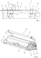
- Figure 1 shows the packaging machine 1 according to the invention, in the present case a so-called thermoformer, which has a deep-drawing station 2, a filling station 7 and a sealing station 15.
- a bottom film web 8, here a plastic film web 8 is pulled off a supply roll and transported in cycles along the packaging machine according to the invention from right to left.
- the film roll is usually mounted on a shaft.
- the bottom film web 8 is transported one pull, whereby several pulls are required to produce a finished package.
- the packaging machine has two transport means (not shown), in the present case two endless chains each, which are arranged to the right and left of the bottom film web 8.
- At least one gear wheel is provided for each chain both at the beginning and at the end of the packaging machine, around which the respective chain is deflected. At least one of these gear wheels is driven.
- the gear wheels in the input area and/or in the output area can be connected to one another, preferably by a rigid shaft.
- Each transport means has a plurality of clamping means which clamp the bottom film web 8 in the inlet area 19 and transfer the movement of the transport means to the bottom film web 8. In the outlet area of the packaging machine, the clamping connection between the transport means and the bottom film web 8 is released again. Downstream of the inlet area 19, a heating means is provided which heats the film web 8, in particular when it is stationary.
- the packaging trays 6 are formed into the heated film web 8.
- a format of packaging trays consisting of several rows and/or several columns, each with several packaging trays, is produced simultaneously during one cycle.
- the lower tool 4 is arranged on a lifting table 5 which, as symbolized by the double arrow, is vertically adjustable, which is done by a lifting device. Before each film feed, the lower tool 4 is lowered and then raised again. As the packaging machine continues, the packaging trays are then filled with the packaging goods 16 in the filling station 7.
- an upper film 14 is firmly attached to the lower film web 8, for example by sealing.
- the upper tool and/or the lower tool are also lowered and raised before and after each film transport.
- the upper film 14 is also unrolled from a film roll that is mounted on a shaft and can be guided in transport means or transported by transport chains, whereby these transport means then only extend from the sealing station and possibly downstream. Otherwise, the statements made about the transport means for the lower film apply.
- the upper film can also be warmed up with a heating medium and deep-drawn.
- a heatable sealing frame is provided as the lower tool 11, for example, which has an opening for each packaging trough, into which the packaging trough dips during sealing, i.e. during the upward movement of the lower sealing tool.
- the upper and lower film webs are pressed together between the upper and lower tools 12, 11 and bond under the influence of heat and pressure. After sealing, the tools 11, 12 are moved apart vertically again.
- a dancer can preferably be provided between the respective supply roll and the sealing tool, which compensates for the intermittent advance of the lower film 8 and thus the intermittent withdrawal of the upper film web 14. The dancer can serve as a film web storage device and/or to generate a certain film tension.
- the person skilled in the art understands that several upper films can be present, for example in a multi-layer pack or a pack with several upper films.
- a dancer is then provided along the course of each upper film.
- a dancer can also be provided in the area of the lower film 8, preferably downstream of its supply roll.
- the longitudinal cutter 17 has a longitudinal cutter cassette 10 in which a rotating knife shaft is provided, which has at least one, usually several longitudinal knives.
- the longitudinal cutter cassette is mounted on the packaging machine above the film transport level.
- the longitudinal knives usually work together with counter knives or squeezing rollers that are located below the film transport level.
- Figures 2 and 3 show the longitudinal cutter cassette 10 according to the invention.
- This has a base plate 30, and in the present case two side parts 31 and preferably a protective hood 25, which is preferably designed essentially U-shaped or V-shaped As in particular Figure 3 can be removed, there is a knife shaft 23 in the longitudinal cutter cassette 10, on which several longitudinal cutting knives 22 are provided.
- the knife shaft is driven in rotation.
- the knife shaft is mounted on the side parts 31 in the raised transport position shown here and is held in the raised position by a lifting or lowering mechanism 24.
- the longitudinal cutter cassette has a bracket 31 with which it can be held or carried, but with which it can also be assembled or disassembled.
- the longitudinal cutter cassette in the present case has four centering means 20 which fix the longitudinal cutter cassette in at least two spatial directions, which are preferably perpendicular to one another.
- the front centering means are circular segment-shaped recesses which interact with a rod on the packaging machine that runs transversely to the transport direction and determine the position of the longitudinal cutter cassette parallel to the transport direction of the film web.
- the position of the longitudinal cutter cassette transverse to the transport direction of the film is determined by the centering means 20 located behind it, which is determined, for example, by a mushroom that protrudes vertically from the film plane and also secures the longitudinal cutter cassette against lifting off.
- the longitudinal cutter cassette preferably has an identifier 22, which can be identified by an identifier, for example another protective cover 41 (see Figures 11 - 12 ).
- the packaging machine can only be put into operation if this identifier recognises the antidote on the protective cover.
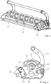
- Figures 4 and 5 show the knife shaft in its raised ( Figure 4 ) transport or in their lowered ( Figure 5 ) working position. It can be seen that in the present case the lifting or lowering mechanism is driven by the support bracket 13, which is provided with a lever. In the present case the lifting or lowering mechanism 24 is even provided as one piece with the lever. In the raised position the knife shaft 23 rests on the mechanism 24 and this prevents the knife shaft from being lowered by gravity. The knife shaft is guided laterally in the side parts 31, whereby, as is particularly evident Figure 5 can be removed, these side parts have vertical guides 43 in the upper area, which secure the shaft against twisting. The shaft can therefore not rotate in its transport position, which represents additional safety for the worker.
- the base plate 30 in the cassette according to the invention is preferably firmly connected to the side parts and not, as is often the case in the prior art, designed to be movable relative to the side parts. This ensures that even through a hard Placing the longitudinal cutter cassette 10 on a surface does not damage the cutting blades. If the blade shaft 23 is to be moved from its transport position to its working position, the support bracket/lever 13 is turned anti-clockwise around the pivot point 27. To do this, a safety device 26 must preferably be activated beforehand so that this movement does not occur unintentionally.
- the blade shaft As soon as the support bracket/lever is turned, the blade shaft, provided there is no obstacle, sinks from its transport position to its working position, which is in Figure 5 and in which the knives protrude from the base plate through slots, for example.
- the lowering of the knife shaft 23 is therefore carried out exclusively by gravity. In the event that the knife shaft does not lower, the worker on site knows that there is an obstacle in the way of the movement and must ensure that this is removed before the knife can be transferred from the transport to the working position.
- FIGS. 6 and 7 show again details of the lowering of the knife shaft 23 from the Figure 6 shown transport in the Figure 7 It can be clearly seen that the blade shaft is guided in a slot 28 in the side wall 31 and that the base plate has recesses, here slots 29. Furthermore, it can be seen that a rotary movement of the support bracket/lever 13 releases the lowering of the blade shaft 23 by means of gravity. In the position shown in Figure 7 In the working position shown, the cutting blades protrude through the base plate and can thus cut the film webs 8, 14. Furthermore, in this position the blade shaft can be connected to a drive shaft 32 so that a torque is transmitted from the drive shaft to the blade shaft.
- the interface between the drive shaft 32 and the blade shaft 23 is preferably secured by a bushing 33, which is preferably mounted on the side wall 31 so that it can be moved longitudinally.
- Figure 8 shows details of the carrying handle/lever 13, or the lifting or lowering mechanism 24 connected to it in one piece.
- Figure 9 shows parts of the safety system of the longitudinal cutter cassette.
- the safety latch 34 To dismantle the longitudinal cutter cassette, the safety latch 34 must be moved from an operating position to a The knife shaft 23 can be moved to the unlocking position, which in the present case is done by a linear movement from right to left.
- the knife shaft 23 In the area in which the safety latch 34 is provided, the knife shaft 23 has a flat 36 which interacts with the flat 36 when the safety latch is moved from right to left and thereby rotates the knife shaft into an unlocking position.
- the movement of the safety latch 34 from right to left also moves a safety pin 37 from right to left, which thereby comes out of engagement with a bushing 33, which thereby releases the transition between the knife shaft 23 and the drive shaft 32, which is symbolized by the movement III, whereby the knife shaft can be dismantled.
- Figure 10 shows once again the interaction of the safety latch 34 with the blade shaft 23, which is held in a very specific angle of rotation by the safety latch 34.
- Figure 9 In the lower part, the positive and/or non-positive connection between the drive shaft 32 and the knife shaft 23 is also shown, which in the present case is designed as a groove-fault connection.
- the longitudinal cutter cassette according to the invention is preferably provided in such a way that a protective cover 41, which protects the longitudinal cutter cassette during operation, can only be mounted when the safety mechanisms of the longitudinal cutter cassette are in a very specific position.
- a protective cover 41 which protects the longitudinal cutter cassette during operation, can only be mounted when the safety mechanisms of the longitudinal cutter cassette are in a very specific position.
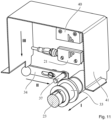
- FIG 11 shows.
- the bushing 33 is pushed over the connection between the two shafts after the connection between the drive shaft 32 and the knife shaft 23 has been made. Only then is there space for the locking pin 37, so that the locking latch 34 can be moved from right to left, as shown by arrow II. Only this sliding movement frees up the space required to place the protective cover 41, as shown by arrow III, from top to bottom on the packaging machine or the base of the slitter cassette.
- This also creates the connection between two electronic components 21, 40, for example 2 RFIDs. This connection unlocks the packaging machine so that it can be started up.
- FIG. 3 Another safety mechanism for the packaging machine according to the invention is shown. Only when the bushing 33, as shown by arrow I, is connected to the connection between the drive shaft and the knife shaft is pushed, the protective cover can be mounted as shown by arrow II and the two components 21, 40 can be brought into contact with each other. Only after this contact, which does not have to be physical but can also be made by electromagnetic waves, for example, can the packaging machine be put into operation.
- the packaging machine and/or the slitter cassette has a sensor 22 which detects the position of the bushing 33 and only allows the packaging machine to start when it is in the area of the connection between the two shafts.
Landscapes
- Engineering & Computer Science (AREA)
- Mechanical Engineering (AREA)
- Life Sciences & Earth Sciences (AREA)
- Forests & Forestry (AREA)
- Auxiliary Devices For And Details Of Packaging Control (AREA)
Claims (10)
- Cassette (10) de coupe longitudinale avec un arbre porte-lames (23) sur lequel est agencée au moins une lame de coupe longitudinale (22) et avec un boîtier (25, 30, 31), l'arbre porte-lames (23) étant apte à être transféré de manière réversible d'une position de transport à une position de travail par abaissement par rapport au boîtier (25, 30, 31), caractérisée en ce que l'abaissement de l'arbre porte-lames (23) s'effectue entièrement par la force de gravité.
- Cassette (10) de coupe longitudinale selon la revendication 1, caractérisée en ce qu'elle comporte un capot de protection (25).
- Cassette (10) de coupe longitudinale selon la revendication 1 ou la revendication 2, caractérisée en ce qu'elle comporte un mécanisme de blocage (33, 34, 37) empêchant la mise en place d'un carter de protection (41) sur la cassette de coupe longitudinale si l'arbre porte-lame (23) n'est pas correctement relié à son entraînement.
- Cassette (10) de coupe longitudinale selon l'une des revendications 1 à 3, caractérisée en ce qu'elle comporte un étrier de support (13).
- Cassette (10) de coupe longitudinale selon la revendication 4, caractérisée en ce que l'étrier de support entraîne un mécanisme de montée/descente (24) de l'arbre porte-lames (23).
- Cassette (10) de coupe longitudinale selon l'une des revendications précédentes, caractérisée en ce qu'elle comprend un boîtier rigide (25, 30, 31).
- Cassette (10) de coupe longitudinale selon l'une des revendications précédentes, caractérisée en ce que l'arbre porte-lames est bloqué en rotation dans la position de transport et/ou bloqué contre l'abaissement et/ou le soulèvement.
- Machine d'emballage (1) pour la fabrication d'un emballage, avec un poste de scellage (15) qui scelle une bande de film (14) sur une auge d'emballage (6) ou scelle ensemble deux extrémités de film, l'auge d'emballage ayant été optionnellement emboutie dans une bande de film (8) ou une bande de film (8, 14) ayant été formée, la machine d'emballage présentant au moins une chaîne (32) en circulation, qui transporte de préférence une bande de film (8, 14) et qui présente un nettoyage de chaîne, et/ou un séchage de chaîne et/ou une lubrification de chaîne, caractérisée en ce que la machine d'emballage présente une cassette (10) de coupe longitudinale selon l'une des revendications précédentes.
- Machine d'emballage selon la revendication 8, caractérisée en ce qu'elle comporte des moyens de centrage coopérant avec des moyens de centrage (20) sur la cassette de coupe longitudinale.
- Machine d'emballage selon l'une des revendications 8 ou 9, caractérisée en ce qu'elle comporte un entraînement manuel permettant de faire tourner la position rotative de l'arbre porte-lame vers une position de montage et/ou de démontage.
Applications Claiming Priority (2)
| Application Number | Priority Date | Filing Date | Title |
|---|---|---|---|
| DE102015212978 | 2015-07-10 | ||
| PCT/EP2016/066148 WO2017009178A1 (fr) | 2015-07-10 | 2016-07-07 | Cassette de coupe longitudinale |
Publications (2)
| Publication Number | Publication Date |
|---|---|
| EP3319876A1 EP3319876A1 (fr) | 2018-05-16 |
| EP3319876B1 true EP3319876B1 (fr) | 2024-08-28 |
Family
ID=56368978
Family Applications (1)
| Application Number | Title | Priority Date | Filing Date |
|---|---|---|---|
| EP16736171.6A Active EP3319876B1 (fr) | 2015-07-10 | 2016-07-07 | Cassette de coupe longitudinale |
Country Status (4)
| Country | Link |
|---|---|
| US (1) | US10696435B2 (fr) |
| EP (1) | EP3319876B1 (fr) |
| ES (1) | ES2996264T3 (fr) |
| WO (1) | WO2017009178A1 (fr) |
Families Citing this family (6)
| Publication number | Priority date | Publication date | Assignee | Title |
|---|---|---|---|---|
| JP6927574B2 (ja) * | 2016-09-21 | 2021-09-01 | デュプロ精工株式会社 | スリッタ、シート裁断機、及びシート加工装置 |
| JP6388143B1 (ja) * | 2017-06-28 | 2018-09-12 | 株式会社日立プラントコンストラクション | 半割切断装置及び半割切断方法 |
| DE102020130469A1 (de) * | 2020-11-18 | 2022-05-19 | Weber Maschinenbau Gmbh Breidenbach | Vorrichtung zum Zuschneiden von Lebensmittelverpackungen entlang einer Längsrichtung und Verfahren zum Betreiben einer solchen Vorrichtung |
| WO2023163495A1 (fr) * | 2022-02-25 | 2023-08-31 | 주식회사 씨젠 | Appareil de découpe de film et procédé de découpe de film de couverture de contenant l'utilisant |
| DE102022104668B4 (de) * | 2022-02-28 | 2024-11-07 | Tantum Sana Gmbh | Schneidevorrichtung zur Segmentierung einer Blisterverpackung |
| DE102024001101A1 (de) * | 2024-04-06 | 2025-10-09 | Mercedes-Benz Group AG | Vorrichtung zum Zuschneiden einer Folienbahn |
Family Cites Families (19)
| Publication number | Priority date | Publication date | Assignee | Title |
|---|---|---|---|---|
| US2307452A (en) * | 1940-08-07 | 1943-01-05 | S & S Corrugated Paper Mach | Slitting and scoring machine |
| GB770948A (en) * | 1954-07-05 | 1957-03-27 | Jagenberg Werke Ag | Improvements in cutting machines for movable webs of paper, cardboard or the like |
| US3343336A (en) * | 1964-06-30 | 1967-09-26 | Sta Hi Corp | Packaging machine |
| US3397508A (en) * | 1965-08-06 | 1968-08-20 | Total Packaging Inc | Thermoplastic packaging machine |
| US3387524A (en) * | 1966-05-27 | 1968-06-11 | William F. Huck | Lever-positioned rotary apparatus for slitting a travelling web |
| US3762251A (en) * | 1972-05-15 | 1973-10-02 | U S Packaging Corp | Apparatus and method for skin packaging articles |
| US3759122A (en) * | 1972-05-22 | 1973-09-18 | Filper Corp | Package separator and corner cutting die for individual portions, and method |
| US4750318A (en) * | 1986-08-21 | 1988-06-14 | Idemitsu Petrochemical Co., Ltd. | Blister packaging apparatus |
| US4819406A (en) * | 1987-09-25 | 1989-04-11 | Sanford Redmond Inc. | Compact form-fill-seal machine for automatic production of sealed packages |
| FR2645790A1 (fr) * | 1989-03-30 | 1990-10-19 | Umat | Appareil de decoupage rotatif |
| US5000069A (en) * | 1989-10-06 | 1991-03-19 | Ithaca Peripheral Inc. | Rotary cutter |
| DE4205798A1 (de) | 1991-03-01 | 1992-09-03 | Dienes Werke | Laengsschneidemaschine mit schneidkassette |
| FR2732638B1 (fr) | 1995-04-10 | 1997-05-09 | Kodak Pathe | Module de coupe pour produit en bande et dispositif de coupe equipe d'au moins un tel module |
| IT1314838B1 (it) | 2000-05-31 | 2003-01-16 | Fosber Spa | Dispositivo e metodo per il cambio d'ordine in un sistema di tagliolongitudinale di un materiale nastriforme |
| JP2003182927A (ja) * | 2001-07-30 | 2003-07-03 | Heidelberger Druckmas Ag | 被印刷材料のための後加工装置に用いられる加工モジュール |
| DE10209090A1 (de) | 2002-03-01 | 2003-09-11 | Heidelberger Druckmasch Ag | Vorrichtung zur digitalen Werkzeugkennung für Druckend- oder Druckweiterbearbeitungsvorrichtungen |
| US20080066427A1 (en) * | 2003-12-17 | 2008-03-20 | Klaus Meyer | Longitudinal Cutter with a Vertically Displaceable Blade and Counter-Roller |
| DE202012100166U1 (de) * | 2012-01-18 | 2013-04-23 | Krug & Priester Gmbh & Co. Kg | Papierstapelschneidmaschine mit Überlastschutz |
| JP6207380B2 (ja) * | 2013-12-20 | 2017-10-04 | デュプロ精工株式会社 | 用紙スリッタ及びこれを備えた用紙加工装置並びにその制御方法 |
-
2016
- 2016-07-07 ES ES16736171T patent/ES2996264T3/es active Active
- 2016-07-07 US US15/738,785 patent/US10696435B2/en active Active
- 2016-07-07 WO PCT/EP2016/066148 patent/WO2017009178A1/fr not_active Ceased
- 2016-07-07 EP EP16736171.6A patent/EP3319876B1/fr active Active
Also Published As
| Publication number | Publication date |
|---|---|
| US10696435B2 (en) | 2020-06-30 |
| WO2017009178A1 (fr) | 2017-01-19 |
| ES2996264T3 (en) | 2025-02-12 |
| EP3319876A1 (fr) | 2018-05-16 |
| US20180186024A1 (en) | 2018-07-05 |
Similar Documents
| Publication | Publication Date | Title |
|---|---|---|
| EP3319876B1 (fr) | Cassette de coupe longitudinale | |
| EP2384866B1 (fr) | Dispositif de découpe pour une machine d'emballage | |
| DE69213852T2 (de) | Vorrichtung zum Herstellen von Füllmaterial aus Bahnmaterial | |
| EP2539125B1 (fr) | Procédé de changement de l'outil supérieur et de l'outil inférieur d'une machine d'emballage | |
| EP2769923B1 (fr) | Machine d'emballage par emboutissage profond avec poste de scellage et procédé | |
| EP3093244B2 (fr) | Dispositif de transport de feuille pour une machine d'emballage | |
| EP3456640B1 (fr) | Tendeur rotatif pour une machine d'emballage | |
| DE69900524T2 (de) | Verpackungsmaschine mit verbesserter Befestigung der Formeinrichtung | |
| EP3844071B1 (fr) | Dispositif pour préparer des récipients en matière plastique en vue de leur utilisation | |
| WO2014082991A1 (fr) | Machine d'emballage comprenant un système de changement d'outil | |
| EP4086049A1 (fr) | Machine d'emballage dotée d'un dispositif de coupe des emballages alimentaires dans une direction longitudinale | |
| EP2241508A2 (fr) | Station de travail d'une machine de conditionnement sous blister | |
| EP2520501A1 (fr) | Procédé d'emballage de paquets en disques à base d'aliments dans une machine à découper ainsi que la machine à découper à cet effet | |
| EP3088315B2 (fr) | Machine d'emballage par emboutissage équipée d'une thermoforeuse | |
| EP2995441B1 (fr) | Machine d'emballage par emboutissage avec dispositif de levage et procédé | |
| EP3484774B1 (fr) | Dispositif de fermeture d'emballages d'expédition | |
| EP3319881B1 (fr) | Machine d'emballage à évacuation de rognures | |
| EP2570351B1 (fr) | Machine d'emballage par emboutissage pour la fabrication d'emballages verticaux ayant une coupe arrière moulée | |
| DE202008013659U1 (de) | Verpackungsmaschine mit Schneidmesser | |
| EP3450134B1 (fr) | Station de formage pour une emboutisseuse-enveloppeuse sous pellicule et procédé de changement d'un poinçon de formage | |
| EP3294636A1 (fr) | Machine d'emballage pourvue d'un dispositif de levage | |
| DE2351069C3 (de) | Maschine zum Aufteilen von Folien, Platten, Tabletts oder anderen Gegenständen in Quer- und Längsrichtung | |
| DE2255442B2 (de) | Tiefziehmaschine zum herstellen von behaeltern aus thermoplastischer folie mit angesiegelten materialstreifen | |
| DE112016002054B4 (de) | Verpackungsmaschine mit einer Spannwelle mit Rollenausrichtung, sowie entsprechendes Verfahren | |
| WO2005058563A1 (fr) | Decoupeur longitudinal a lame deplaçable verticalement et cylindre antagoniste |
Legal Events
| Date | Code | Title | Description |
|---|---|---|---|
| STAA | Information on the status of an ep patent application or granted ep patent |
Free format text: STATUS: THE INTERNATIONAL PUBLICATION HAS BEEN MADE |
|
| PUAI | Public reference made under article 153(3) epc to a published international application that has entered the european phase |
Free format text: ORIGINAL CODE: 0009012 |
|
| STAA | Information on the status of an ep patent application or granted ep patent |
Free format text: STATUS: REQUEST FOR EXAMINATION WAS MADE |
|
| 17P | Request for examination filed |
Effective date: 20171204 |
|
| AK | Designated contracting states |
Kind code of ref document: A1 Designated state(s): AL AT BE BG CH CY CZ DE DK EE ES FI FR GB GR HR HU IE IS IT LI LT LU LV MC MK MT NL NO PL PT RO RS SE SI SK SM TR |
|
| AX | Request for extension of the european patent |
Extension state: BA ME |
|
| DAV | Request for validation of the european patent (deleted) | ||
| DAX | Request for extension of the european patent (deleted) | ||
| STAA | Information on the status of an ep patent application or granted ep patent |
Free format text: STATUS: EXAMINATION IS IN PROGRESS |
|
| 17Q | First examination report despatched |
Effective date: 20191014 |
|
| GRAP | Despatch of communication of intention to grant a patent |
Free format text: ORIGINAL CODE: EPIDOSNIGR1 |
|
| STAA | Information on the status of an ep patent application or granted ep patent |
Free format text: STATUS: GRANT OF PATENT IS INTENDED |
|
| INTG | Intention to grant announced |
Effective date: 20240419 |
|
| GRAS | Grant fee paid |
Free format text: ORIGINAL CODE: EPIDOSNIGR3 |
|
| GRAA | (expected) grant |
Free format text: ORIGINAL CODE: 0009210 |
|
| STAA | Information on the status of an ep patent application or granted ep patent |
Free format text: STATUS: THE PATENT HAS BEEN GRANTED |
|
| P01 | Opt-out of the competence of the unified patent court (upc) registered |
Free format text: CASE NUMBER: APP_39394/2024 Effective date: 20240702 |
|
| AK | Designated contracting states |
Kind code of ref document: B1 Designated state(s): AL AT BE BG CH CY CZ DE DK EE ES FI FR GB GR HR HU IE IS IT LI LT LU LV MC MK MT NL NO PL PT RO RS SE SI SK SM TR |
|
| REG | Reference to a national code |
Ref country code: GB Ref legal event code: FG4D Free format text: NOT ENGLISH |
|
| REG | Reference to a national code |
Ref country code: CH Ref legal event code: EP |
|
| REG | Reference to a national code |
Ref country code: DE Ref legal event code: R096 Ref document number: 502016016693 Country of ref document: DE |
|
| REG | Reference to a national code |
Ref country code: IE Ref legal event code: FG4D Free format text: LANGUAGE OF EP DOCUMENT: GERMAN |
|
| REG | Reference to a national code |
Ref country code: NL Ref legal event code: FP |
|
| REG | Reference to a national code |
Ref country code: LT Ref legal event code: MG9D |
|
| PG25 | Lapsed in a contracting state [announced via postgrant information from national office to epo] |
Ref country code: NO Free format text: LAPSE BECAUSE OF FAILURE TO SUBMIT A TRANSLATION OF THE DESCRIPTION OR TO PAY THE FEE WITHIN THE PRESCRIBED TIME-LIMIT Effective date: 20241128 |
|
| PG25 | Lapsed in a contracting state [announced via postgrant information from national office to epo] |
Ref country code: PL Free format text: LAPSE BECAUSE OF FAILURE TO SUBMIT A TRANSLATION OF THE DESCRIPTION OR TO PAY THE FEE WITHIN THE PRESCRIBED TIME-LIMIT Effective date: 20240828 Ref country code: PT Free format text: LAPSE BECAUSE OF FAILURE TO SUBMIT A TRANSLATION OF THE DESCRIPTION OR TO PAY THE FEE WITHIN THE PRESCRIBED TIME-LIMIT Effective date: 20241230 Ref country code: FI Free format text: LAPSE BECAUSE OF FAILURE TO SUBMIT A TRANSLATION OF THE DESCRIPTION OR TO PAY THE FEE WITHIN THE PRESCRIBED TIME-LIMIT Effective date: 20240828 Ref country code: GR Free format text: LAPSE BECAUSE OF FAILURE TO SUBMIT A TRANSLATION OF THE DESCRIPTION OR TO PAY THE FEE WITHIN THE PRESCRIBED TIME-LIMIT Effective date: 20241129 |
|
| PG25 | Lapsed in a contracting state [announced via postgrant information from national office to epo] |
Ref country code: BG Free format text: LAPSE BECAUSE OF FAILURE TO SUBMIT A TRANSLATION OF THE DESCRIPTION OR TO PAY THE FEE WITHIN THE PRESCRIBED TIME-LIMIT Effective date: 20240828 |
|
| PG25 | Lapsed in a contracting state [announced via postgrant information from national office to epo] |
Ref country code: LV Free format text: LAPSE BECAUSE OF FAILURE TO SUBMIT A TRANSLATION OF THE DESCRIPTION OR TO PAY THE FEE WITHIN THE PRESCRIBED TIME-LIMIT Effective date: 20240828 |
|
| PG25 | Lapsed in a contracting state [announced via postgrant information from national office to epo] |
Ref country code: IS Free format text: LAPSE BECAUSE OF FAILURE TO SUBMIT A TRANSLATION OF THE DESCRIPTION OR TO PAY THE FEE WITHIN THE PRESCRIBED TIME-LIMIT Effective date: 20241228 |
|
| PG25 | Lapsed in a contracting state [announced via postgrant information from national office to epo] |
Ref country code: HR Free format text: LAPSE BECAUSE OF FAILURE TO SUBMIT A TRANSLATION OF THE DESCRIPTION OR TO PAY THE FEE WITHIN THE PRESCRIBED TIME-LIMIT Effective date: 20240828 |
|
| PG25 | Lapsed in a contracting state [announced via postgrant information from national office to epo] |
Ref country code: RS Free format text: LAPSE BECAUSE OF FAILURE TO SUBMIT A TRANSLATION OF THE DESCRIPTION OR TO PAY THE FEE WITHIN THE PRESCRIBED TIME-LIMIT Effective date: 20241128 |
|
| PG25 | Lapsed in a contracting state [announced via postgrant information from national office to epo] |
Ref country code: RS Free format text: LAPSE BECAUSE OF FAILURE TO SUBMIT A TRANSLATION OF THE DESCRIPTION OR TO PAY THE FEE WITHIN THE PRESCRIBED TIME-LIMIT Effective date: 20241128 Ref country code: PT Free format text: LAPSE BECAUSE OF FAILURE TO SUBMIT A TRANSLATION OF THE DESCRIPTION OR TO PAY THE FEE WITHIN THE PRESCRIBED TIME-LIMIT Effective date: 20241230 Ref country code: PL Free format text: LAPSE BECAUSE OF FAILURE TO SUBMIT A TRANSLATION OF THE DESCRIPTION OR TO PAY THE FEE WITHIN THE PRESCRIBED TIME-LIMIT Effective date: 20240828 Ref country code: NO Free format text: LAPSE BECAUSE OF FAILURE TO SUBMIT A TRANSLATION OF THE DESCRIPTION OR TO PAY THE FEE WITHIN THE PRESCRIBED TIME-LIMIT Effective date: 20241128 Ref country code: LV Free format text: LAPSE BECAUSE OF FAILURE TO SUBMIT A TRANSLATION OF THE DESCRIPTION OR TO PAY THE FEE WITHIN THE PRESCRIBED TIME-LIMIT Effective date: 20240828 Ref country code: IS Free format text: LAPSE BECAUSE OF FAILURE TO SUBMIT A TRANSLATION OF THE DESCRIPTION OR TO PAY THE FEE WITHIN THE PRESCRIBED TIME-LIMIT Effective date: 20241228 Ref country code: HR Free format text: LAPSE BECAUSE OF FAILURE TO SUBMIT A TRANSLATION OF THE DESCRIPTION OR TO PAY THE FEE WITHIN THE PRESCRIBED TIME-LIMIT Effective date: 20240828 Ref country code: GR Free format text: LAPSE BECAUSE OF FAILURE TO SUBMIT A TRANSLATION OF THE DESCRIPTION OR TO PAY THE FEE WITHIN THE PRESCRIBED TIME-LIMIT Effective date: 20241129 Ref country code: FI Free format text: LAPSE BECAUSE OF FAILURE TO SUBMIT A TRANSLATION OF THE DESCRIPTION OR TO PAY THE FEE WITHIN THE PRESCRIBED TIME-LIMIT Effective date: 20240828 Ref country code: BG Free format text: LAPSE BECAUSE OF FAILURE TO SUBMIT A TRANSLATION OF THE DESCRIPTION OR TO PAY THE FEE WITHIN THE PRESCRIBED TIME-LIMIT Effective date: 20240828 |
|
| REG | Reference to a national code |
Ref country code: ES Ref legal event code: FG2A Ref document number: 2996264 Country of ref document: ES Kind code of ref document: T3 Effective date: 20250212 |
|
| PG25 | Lapsed in a contracting state [announced via postgrant information from national office to epo] |
Ref country code: SM Free format text: LAPSE BECAUSE OF FAILURE TO SUBMIT A TRANSLATION OF THE DESCRIPTION OR TO PAY THE FEE WITHIN THE PRESCRIBED TIME-LIMIT Effective date: 20240828 Ref country code: DK Free format text: LAPSE BECAUSE OF FAILURE TO SUBMIT A TRANSLATION OF THE DESCRIPTION OR TO PAY THE FEE WITHIN THE PRESCRIBED TIME-LIMIT Effective date: 20240828 Ref country code: RO Free format text: LAPSE BECAUSE OF FAILURE TO SUBMIT A TRANSLATION OF THE DESCRIPTION OR TO PAY THE FEE WITHIN THE PRESCRIBED TIME-LIMIT Effective date: 20240828 |
|
| PG25 | Lapsed in a contracting state [announced via postgrant information from national office to epo] |
Ref country code: EE Free format text: LAPSE BECAUSE OF FAILURE TO SUBMIT A TRANSLATION OF THE DESCRIPTION OR TO PAY THE FEE WITHIN THE PRESCRIBED TIME-LIMIT Effective date: 20240828 |
|
| PG25 | Lapsed in a contracting state [announced via postgrant information from national office to epo] |
Ref country code: CZ Free format text: LAPSE BECAUSE OF FAILURE TO SUBMIT A TRANSLATION OF THE DESCRIPTION OR TO PAY THE FEE WITHIN THE PRESCRIBED TIME-LIMIT Effective date: 20240828 |
|
| PG25 | Lapsed in a contracting state [announced via postgrant information from national office to epo] |
Ref country code: SK Free format text: LAPSE BECAUSE OF FAILURE TO SUBMIT A TRANSLATION OF THE DESCRIPTION OR TO PAY THE FEE WITHIN THE PRESCRIBED TIME-LIMIT Effective date: 20240828 |
|
| REG | Reference to a national code |
Ref country code: DE Ref legal event code: R097 Ref document number: 502016016693 Country of ref document: DE |
|
| PLBE | No opposition filed within time limit |
Free format text: ORIGINAL CODE: 0009261 |
|
| STAA | Information on the status of an ep patent application or granted ep patent |
Free format text: STATUS: NO OPPOSITION FILED WITHIN TIME LIMIT |
|
| 26N | No opposition filed |
Effective date: 20250530 |
|
| PGFP | Annual fee paid to national office [announced via postgrant information from national office to epo] |
Ref country code: NL Payment date: 20250731 Year of fee payment: 10 |
|
| PG25 | Lapsed in a contracting state [announced via postgrant information from national office to epo] |
Ref country code: SE Free format text: LAPSE BECAUSE OF FAILURE TO SUBMIT A TRANSLATION OF THE DESCRIPTION OR TO PAY THE FEE WITHIN THE PRESCRIBED TIME-LIMIT Effective date: 20240828 |
|
| PGFP | Annual fee paid to national office [announced via postgrant information from national office to epo] |
Ref country code: ES Payment date: 20250801 Year of fee payment: 10 |
|
| PGFP | Annual fee paid to national office [announced via postgrant information from national office to epo] |
Ref country code: DE Payment date: 20250801 Year of fee payment: 10 |
|
| PGFP | Annual fee paid to national office [announced via postgrant information from national office to epo] |
Ref country code: IT Payment date: 20250731 Year of fee payment: 10 |
|
| REG | Reference to a national code |
Ref country code: CH Ref legal event code: H13 Free format text: ST27 STATUS EVENT CODE: U-0-0-H10-H13 (AS PROVIDED BY THE NATIONAL OFFICE) Effective date: 20260224 |
|
| PG25 | Lapsed in a contracting state [announced via postgrant information from national office to epo] |
Ref country code: LU Free format text: LAPSE BECAUSE OF NON-PAYMENT OF DUE FEES Effective date: 20250707 |
|
| GBPC | Gb: european patent ceased through non-payment of renewal fee |
Effective date: 20250707 |
|
| REG | Reference to a national code |
Ref country code: BE Ref legal event code: MM Effective date: 20250731 |
|
| PG25 | Lapsed in a contracting state [announced via postgrant information from national office to epo] |
Ref country code: GB Free format text: LAPSE BECAUSE OF NON-PAYMENT OF DUE FEES Effective date: 20250707 |
|
| PG25 | Lapsed in a contracting state [announced via postgrant information from national office to epo] |
Ref country code: BE Free format text: LAPSE BECAUSE OF NON-PAYMENT OF DUE FEES Effective date: 20250731 |
|
| PG25 | Lapsed in a contracting state [announced via postgrant information from national office to epo] |
Ref country code: FR Free format text: LAPSE BECAUSE OF NON-PAYMENT OF DUE FEES Effective date: 20250731 |
|
| PG25 | Lapsed in a contracting state [announced via postgrant information from national office to epo] |
Ref country code: CH Free format text: LAPSE BECAUSE OF NON-PAYMENT OF DUE FEES Effective date: 20250731 |