EP3321526B1 - Schubgleitlager - Google Patents
Schubgleitlager Download PDFInfo
- Publication number
- EP3321526B1 EP3321526B1 EP17202614.8A EP17202614A EP3321526B1 EP 3321526 B1 EP3321526 B1 EP 3321526B1 EP 17202614 A EP17202614 A EP 17202614A EP 3321526 B1 EP3321526 B1 EP 3321526B1
- Authority
- EP
- European Patent Office
- Prior art keywords
- annular
- inner peripheral
- radial
- outer peripheral
- seal
- Prior art date
- Legal status (The legal status is an assumption and is not a legal conclusion. Google has not performed a legal analysis and makes no representation as to the accuracy of the status listed.)
- Active
Links
Images






Classifications
-
- F—MECHANICAL ENGINEERING; LIGHTING; HEATING; WEAPONS; BLASTING
- F16—ENGINEERING ELEMENTS AND UNITS; GENERAL MEASURES FOR PRODUCING AND MAINTAINING EFFECTIVE FUNCTIONING OF MACHINES OR INSTALLATIONS; THERMAL INSULATION IN GENERAL
- F16C—SHAFTS; FLEXIBLE SHAFTS; ELEMENTS OR CRANKSHAFT MECHANISMS; ROTARY BODIES OTHER THAN GEARING ELEMENTS; BEARINGS
- F16C17/00—Sliding-contact bearings for exclusively rotary movement
- F16C17/04—Sliding-contact bearings for exclusively rotary movement for axial load only
-
- B—PERFORMING OPERATIONS; TRANSPORTING
- B60—VEHICLES IN GENERAL
- B60G—VEHICLE SUSPENSION ARRANGEMENTS
- B60G15/00—Resilient suspensions characterised by arrangement, location or type of combined spring and vibration damper, e.g. telescopic type
- B60G15/02—Resilient suspensions characterised by arrangement, location or type of combined spring and vibration damper, e.g. telescopic type having mechanical spring
- B60G15/06—Resilient suspensions characterised by arrangement, location or type of combined spring and vibration damper, e.g. telescopic type having mechanical spring and fluid damper
- B60G15/067—Resilient suspensions characterised by arrangement, location or type of combined spring and vibration damper, e.g. telescopic type having mechanical spring and fluid damper characterised by the mounting on the vehicle body or chassis of the spring and damper unit
- B60G15/068—Resilient suspensions characterised by arrangement, location or type of combined spring and vibration damper, e.g. telescopic type having mechanical spring and fluid damper characterised by the mounting on the vehicle body or chassis of the spring and damper unit specially adapted for MacPherson strut-type suspension
-
- F—MECHANICAL ENGINEERING; LIGHTING; HEATING; WEAPONS; BLASTING
- F16—ENGINEERING ELEMENTS AND UNITS; GENERAL MEASURES FOR PRODUCING AND MAINTAINING EFFECTIVE FUNCTIONING OF MACHINES OR INSTALLATIONS; THERMAL INSULATION IN GENERAL
- F16C—SHAFTS; FLEXIBLE SHAFTS; ELEMENTS OR CRANKSHAFT MECHANISMS; ROTARY BODIES OTHER THAN GEARING ELEMENTS; BEARINGS
- F16C17/00—Sliding-contact bearings for exclusively rotary movement
- F16C17/10—Sliding-contact bearings for exclusively rotary movement for both radial and axial load
-
- F—MECHANICAL ENGINEERING; LIGHTING; HEATING; WEAPONS; BLASTING
- F16—ENGINEERING ELEMENTS AND UNITS; GENERAL MEASURES FOR PRODUCING AND MAINTAINING EFFECTIVE FUNCTIONING OF MACHINES OR INSTALLATIONS; THERMAL INSULATION IN GENERAL
- F16C—SHAFTS; FLEXIBLE SHAFTS; ELEMENTS OR CRANKSHAFT MECHANISMS; ROTARY BODIES OTHER THAN GEARING ELEMENTS; BEARINGS
- F16C17/00—Sliding-contact bearings for exclusively rotary movement
- F16C17/12—Sliding-contact bearings for exclusively rotary movement characterised by features not related to the direction of the load
- F16C17/18—Sliding-contact bearings for exclusively rotary movement characterised by features not related to the direction of the load with floating brasses or brushing, rotatable at a reduced speed
-
- F—MECHANICAL ENGINEERING; LIGHTING; HEATING; WEAPONS; BLASTING
- F16—ENGINEERING ELEMENTS AND UNITS; GENERAL MEASURES FOR PRODUCING AND MAINTAINING EFFECTIVE FUNCTIONING OF MACHINES OR INSTALLATIONS; THERMAL INSULATION IN GENERAL
- F16C—SHAFTS; FLEXIBLE SHAFTS; ELEMENTS OR CRANKSHAFT MECHANISMS; ROTARY BODIES OTHER THAN GEARING ELEMENTS; BEARINGS
- F16C33/00—Parts of bearings; Special methods for making bearings or parts thereof
- F16C33/02—Parts of sliding-contact bearings
- F16C33/04—Brasses; Bushes; Linings
- F16C33/20—Sliding surface consisting mainly of plastics
- F16C33/201—Composition of the plastic
-
- F—MECHANICAL ENGINEERING; LIGHTING; HEATING; WEAPONS; BLASTING
- F16—ENGINEERING ELEMENTS AND UNITS; GENERAL MEASURES FOR PRODUCING AND MAINTAINING EFFECTIVE FUNCTIONING OF MACHINES OR INSTALLATIONS; THERMAL INSULATION IN GENERAL
- F16C—SHAFTS; FLEXIBLE SHAFTS; ELEMENTS OR CRANKSHAFT MECHANISMS; ROTARY BODIES OTHER THAN GEARING ELEMENTS; BEARINGS
- F16C33/00—Parts of bearings; Special methods for making bearings or parts thereof
- F16C33/72—Sealings
- F16C33/74—Sealings of sliding-contact bearings
-
- B—PERFORMING OPERATIONS; TRANSPORTING
- B60—VEHICLES IN GENERAL
- B60G—VEHICLE SUSPENSION ARRANGEMENTS
- B60G2204/00—Indexing codes related to suspensions per se or to auxiliary parts
- B60G2204/40—Auxiliary suspension parts; Adjustment of suspensions
- B60G2204/418—Bearings, e.g. ball or roller bearings
-
- F—MECHANICAL ENGINEERING; LIGHTING; HEATING; WEAPONS; BLASTING
- F16—ENGINEERING ELEMENTS AND UNITS; GENERAL MEASURES FOR PRODUCING AND MAINTAINING EFFECTIVE FUNCTIONING OF MACHINES OR INSTALLATIONS; THERMAL INSULATION IN GENERAL
- F16C—SHAFTS; FLEXIBLE SHAFTS; ELEMENTS OR CRANKSHAFT MECHANISMS; ROTARY BODIES OTHER THAN GEARING ELEMENTS; BEARINGS
- F16C2326/00—Articles relating to transporting
- F16C2326/01—Parts of vehicles in general
- F16C2326/05—Vehicle suspensions, e.g. bearings, pivots or connecting rods used therein
-
- F—MECHANICAL ENGINEERING; LIGHTING; HEATING; WEAPONS; BLASTING
- F16—ENGINEERING ELEMENTS AND UNITS; GENERAL MEASURES FOR PRODUCING AND MAINTAINING EFFECTIVE FUNCTIONING OF MACHINES OR INSTALLATIONS; THERMAL INSULATION IN GENERAL
- F16C—SHAFTS; FLEXIBLE SHAFTS; ELEMENTS OR CRANKSHAFT MECHANISMS; ROTARY BODIES OTHER THAN GEARING ELEMENTS; BEARINGS
- F16C2361/00—Apparatus or articles in engineering in general
- F16C2361/53—Spring-damper, e.g. gas springs
Definitions
- the present invention relates to a synthetic resin-made thrust sliding bearing, and more particularly to a thrust sliding bearing which is suitably incorporated as a thrust sliding bearing of a strut-type suspension (Macpherson type) in a four-wheeled motor vehicle.
- a thrust sliding bearing which is suitably incorporated as a thrust sliding bearing of a strut-type suspension (Macpherson type) in a four-wheeled motor vehicle.
- a synthetic resin-made sliding bearing which includes a synthetic resin-made lower casing, a synthetic resin-made upper casing superposed on this lower casing, and a synthetic resin-made sliding bearing means interposed between the upper and lower casings, the synthetic resin-made sliding bearing comprised of an outer resiliently sealing means disposed on an outer peripheral side between the upper and lower casings and an inner resiliently sealing means disposed on an inner peripheral side between the upper and lower casings.
- a synthetic resin-made sliding bearing which includes a synthetic resin-made lower casing, a synthetic resin-made upper casing superposed on this lower casing, and a synthetic resin-made thrust sliding bearing member disposed in a space between the upper and lower casings, the synthetic resin-made sliding bearing comprised of an outer sealing means disposed on an outer peripheral side in the space between the upper and lower casings and an inner labyrinth sealing means disposed on an inner peripheral side in the space between the upper and lower casings.
- a synthetic resin-made sliding bearing which includes a synthetic resin-made lower casing, a synthetic resin-made upper casing superposed on this lower casing, and a synthetic resin-made sliding bearing means interposed between the upper and lower casings, the synthetic resin-made sliding bearing comprised of a resiliently sealing means which is disposed in such a manner as to cover an outer surface of the lower casing and which seals outer and inner annular openings of a space between the upper and lower casings at both annular end portions.
- a synthetic resin-made sliding bearing which includes an upper casing having an annular lower surface, a lower casing which is superposed on this upper casing so as to be rotatable about an axis of the upper casing and has an annular upper surface, and an annular thrust sliding bearing piece disposed in an annular space between the annular lower surface and the annular upper surface, the sliding bearing comprised of a sealing means disposed on at least one side of an outer peripheral side and an inner peripheral side of the annular space.
- a synthetic resin-made sliding bearing which includes a synthetic resin-made upper casing having an annular lower surface, a synthetic resin-made lower casing having an annular upper surface, and a thrust sliding bearing piece disposed in an annular gap between the annular lower surface and the annular upper surface.
- EP-A2-1,555,144 discloses a bearing, comprising two rings with rolling bodies between them, a cover in which the first ring is fitted, and a seal that is fixed to the cover and interacts with a fixed or moving surface.
- the seal has at least one lip and is attached to the cover by a series of axial projections on its connecting portion.
- the projections, which penetrate at least partly into one or more cavities in the cover, can be in two concentric rings and made in the shape of rivets.
- the present invention has been devised in view of the above-described aspects, and its object is to provide a thrust sliding bearing which excels in the assembling efficiency and replaceability, makes it possible to reduce the manufacturing cost, and is capable of further improving the durability and sealability.
- a thrust sliding bearing in accordance with the present invention comprises:
- each of the plurality of connecting portions is integrally connected at its one end portion to the inner peripheral-side annular seal portion and at its other end portion to the outer peripheral-side annular seal portion, so that the number of parts can be reduced, and the assembling efficiency and the replaceability are made to excel, making it possible to attain a reduction in the manufacturing cost. Moreover, since each of the plurality of connecting portions is passed between the thrust sliding bearing piece and the annular protrusion of the lower casing, the durability can be improved by eliminating the possibility of coming off.
- the seal member has the inner peripheral-side annular seal portion and the outer peripheral-side annular seal portion for sealing the gaps between the inner peripheral-side suspended cylindrical portion of the upper casing and the lower casing base portion of the lower casing on the radial inner peripheral side and outer peripheral side, the sealability can be further improved.
- the thrust sliding bearing in accordance with the present invention is preferably used as a thrust sliding bearing of a strut-type suspension in a four-wheeled motor vehicle.
- the synthetic resin for forming the upper casing and the lower casing may be a thermoplastic synthetic resin such as polyacetal resin, polyamide resin, or polyester resin.
- the synthetic resin for forming the thrust sliding bearing piece may be a thermoplastic synthetic resin such as polyacetal resin, polyamide resin, polyolefin resin, or polyester resin.
- the synthetic resin for forming the seal member it is possible to cite polyurethane as a preferred example.
- a thrust sliding bearing which excels in the assembling efficiency and replaceability, makes it possible to reduce the manufacturing cost, and is capable of further improving the durability and sealability.
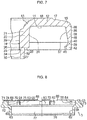
- a thrust sliding bearing 1 in accordance with this embodiment for use in a strut-type suspension of a four-wheeled motor vehicle is comprised of a synthetic resin-made upper casing 2 which is fixed to a vehicle body side via a mounting member; a synthetic resin-made lower casing 3 which is superposed on the upper casing 2 so as to be rotatable about an axis O in a circumferential direction R relative to the upper casing 2 and is fixed to a spring seat side of a coil spring of the suspension; a synthetic resin-made thrust sliding bearing piece 5 disposed in an annular space 4 between the upper casing 2 and the lower casing 3; and a synthetic resin-made seal member 8 for sealing respective other end portions, communicating with the outside, of a gap 6 on an inner peripheral side and a gap 7 on an outer peripheral side in a radial direction A between the upper casing 2 and the lower casing 3, the gap 6 and the gap 7 respectively communicating with the annular space 4 at their one annular end portions
- the upper casing 2 integrally includes an annular upper casing base portion 12 having an annular lower surface 11 in an axial direction B, an inner peripheral-side suspended cylindrical portion 14 suspended from an inner peripheral end portion 13 in a radial direction A of the annular lower surface 11 of the upper casing base portion 12, an outer peripheral-side suspended cylindrical portion 16 suspended from an outer peripheral end portion 15 in the radial direction A of the annular lower surface 11 of the upper casing base portion 12, and an annular seat portion 18 formed protrudingly on a central portion in the radial direction A of an annular upper surface 17 of the upper casing base portion 12.
- the inner peripheral-side suspended cylindrical portion 14 has a thick-walled cylindrical portion 22 connected at its upper end portion 21 to the inner peripheral end portion 13 of the annular lower surface 11 of the upper casing base portion 12, as well as a thin-walled cylindrical portion 27 which is connected at its upper end portion 23 to a lower end portion 26 of the thick-walled cylindrical portion 22 via an inner peripheral-side stepped annular surface 24 and an outer peripheral-side stepped annular surface 25 and is thinner-walled relative to the thick-walled cylindrical portion 22.
- the thick-walled cylindrical portion 22 and the thin-walled cylindrical portion 27 respectively have cylindrical inner peripheral surfaces 29 and 30 which define a through hole 28 through which a shaft member of a strut-type suspension is inserted.
- the thick-walled cylindrical portion 22 has a cylindrical outer peripheral surface 31, and the thin-walled cylindrical portion 27 has a cylindrical outer peripheral surface 32 smaller in diameter than the outer peripheral surface 31.
- the outer peripheral-side suspended cylindrical portion 16 having a cylindrical outer peripheral surface 35 includes a cross-sectionally trapezoidal cylindrical portion 38 which is connected at its upper end portion 36 to the outer peripheral end portion 15 of the annular lower surface 11 of the upper casing base portion 12 and has an inner peripheral surface 37 which is gradually enlarged in diameter as viewed in a direction away from the annular lower surface 11 of the upper casing base portion 12, as well as an enlarged cylindrical portion 42 which is connected at its upper end portion 39 to a lower end portion 40 of the cross-sectionally trapezoidal cylindrical portion 38 and has an inner peripheral surface 41 which is gradually reduced in diameter as viewed in a direction away from the lower end portion 40 of the cross-sectionally trapezoidal cylindrical portion 38 and is gradually enlarged in diameter as viewed in a direction away from this reduced-diameter end.
- the lower casing 3 integrally includes an annular lower casing base portion 52 having an annular upper surface 51; an annular protrusion 53 protruding from the annular upper surface 51 of the lower casing base portion 52 toward the annular lower surface 11 of the upper casing base portion 12; an annular inner peripheral-side protrusion 57 protruding from the annular upper surface 51 toward the annular lower surface 11 of the upper casing base portion 12 on an inner peripheral side 56 of the annular upper surface 51 of the lower casing base portion 52 so as to form an inner peripheral-side annular recess 55 in cooperation with a cylindrical inner peripheral surface 54 in the radial direction A of the annular protrusion 53; a hollow cylindrical portion 60 protruding from an inner peripheral portion 59 of an annular lower surface 58 of the lower casing base portion 52 so as to extend away from the annular lower surface 58; an annular protruding portion 63 protruding inwardly from a cylindrical
- the annular protrusion 53 includes an annular notched stepped portion 71 at an outer peripheral portion of its upper surface 65; an annular arcuate recessed outer peripheral surface 73 which is connected at its lower end portion 72 to the outer peripheral end portion of the annular upper surface 51 of the lower casing base portion 52 and is gradually reduced in diameter as viewed in a direction away from the annular upper surface 51 of the lower casing base portion 52; a plurality of upper surface grooves 74 arranged on its upper surface 65 by being spaced apart from each other at equal intervals in the circumferential direction R; and a plurality of inner peripheral surface grooves 75 which are arranged on its inner peripheral surface 54 by being spaced apart from each other at equal intervals in the circumferential direction R in such a manner as to respectively communicate with the upper surface grooves 74 and also communicate with the inner peripheral-side annular recess 55.
- the inner peripheral surface 62 of the hollow cylindrical portion 60 and an annular inner peripheral surface 76 of the protruding portion 63 define a through hole 77 which is concentric with the through hole 28 and through which the shaft member of the strut-type suspension is inserted.
- the synthetic resin-made thrust sliding bearing piece 5 disposed in the annular space 4 between the annular lower surface 11 of the upper casing base portion 12 and the annular upper surface 51 of the lower casing base portion 52 includes an annular radial bearing piece portion 83 having an annular upper surface 81 which is brought into slidable contact with the annular lower surface 11 of the upper casing base portion 12 and an annular lower surface 82 which is brought into contact with the upper surface 65 of the annular protrusion 53; a cylindrical axial bearing piece portion 86 which is integrally formed at its one end portion on one end portion of the radial bearing piece portion 83 in such a manner as to extend downwardly and has an annular inner side surface 84 which is brought into slidable contact with the outer peripheral surface 31 of the thick-walled cylindrical portion 22 and an annular outer side surface 85 which is brought into contact with the inner peripheral surface 54 of the annular protrusion 53; and a plurality of radial project
- the radial bearing piece portion 83 has an annular groove 91 provided on an inner peripheral side of the upper surface 81 and a plurality of radial grooves 92 which are open at their one ends to the annular groove 91 and is open at their other ends to the outer peripheral surface 87, and which are provided on the upper surface 81 by being spaced apart at equal intervals in the circumferential direction R.
- the axial bearing piece portion 86 has a plurality of axial grooves 93 which are open at their both ends and are provided on the inner side surface 84 by being spaced apart at equal intervals in the circumferential direction R.
- the aforementioned annular groove 91, radial grooves 92, and axial grooves 93 serve as a lubricating oil sump.
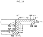
- the seal member 8 has on its inner peripheral side a flexible inner peripheral-side annular seal portion 103 which is elastically brought into flexural contact with the outer peripheral surface 32 of the thin-walled cylindrical portion 27 of the inner peripheral-side suspended cylindrical portion 14, so as to seal the gap 6 between the thin-walled cylindrical portion 27, i.e., an axial end portion 101 of the inner peripheral-side suspended cylindrical portion 14 of the upper casing 2, and the annular inner peripheral-side protrusion 57, i.e., an inner peripheral end portion 102 of the lower casing base portion 52 of the lower casing 3, and has on its outer peripheral side a flexible outer peripheral-side annular seal portion 106 which is elastically brought into flexural contact with the inner peripheral surface 37 of the cross-sectionally trapezoidal cylindrical portion 38 of the outer peripheral-side suspended cylindrical portion 16, so as to seal the gap 7 between an axial end portion 104 of the outer peripheral-side suspended cylindrical portion 16 of the upper casing 2 and an outer peripheral end portion 105
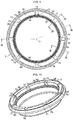
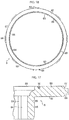
- Each of the plurality of connecting portions 107 which are arranged by being spaced apart from each other at equal intervals in the circumferential direction R has a radial connecting portion 113 which is integrally connected at its one end portion 111 to an annular inner peripheral end portion 112 of the outer peripheral-side annular seal portion 106, as well as an axial connecting portion 118 which is integrally connected at its one end portion 114 to another end portion 115 of the radial connecting portion 113 and at its other end portion 116 to an annular outer peripheral end portion 117 of the inner peripheral-side annular seal portion 103.
- Each of the plurality of connecting portions 107 is integrally connected at its other end portion 116 to the inner peripheral-side annular seal portion 103 and at its one end portion 111 to the outer peripheral-side annular seal portion 106 by being passed between the thrust sliding bearing piece 5 and the annular protrusion 53 of the lower casing 3 as the radial connecting portion 113 is received by each of the upper surface grooves 74 and the axial connecting portion 118 is received by each of the inner peripheral surface grooves 75.
- the inner peripheral-side annular seal portion 103 includes an annular inner peripheral seal base portion 131 which is integrally connected at its annular outer peripheral end portion 117 to an axial lower end portion, i.e., the other end portion 116, of the axial connecting portion 118 and which is fitted to the inner peripheral-side annular recess 55, as well as a flexible inner peripheral seal portion 134 which is connected at its outer peripheral end portion 132 to an inner peripheral end portion 133 of the inner peripheral seal base portion 131 and which is elastically brought into flexural contact with the outer peripheral surface 32 of the thin-walled cylindrical portion 27 of the inner peripheral-side suspended cylindrical portion 14.
- the inner peripheral seal portion 134 extends diagonally downwardly from the outer peripheral end portion 132 which has a smaller thickness than the thickness of the inner peripheral seal base portion 131 and which is connected to the inner peripheral end portion 133 of the inner peripheral seal base portion 131.
- the outer peripheral-side annular seal portion 106 includes an annular outer peripheral seal base portion 141 which is integrally connected at its annular inner peripheral end portion 112 to an outer lower end portion, i.e., the one end portion 111, of the radial connecting portion 113 and which is fitted to the notched stepped portion 71, as well as a flexible outer peripheral seal portion 144 which is connected at its inner peripheral end portion 142 to an outer peripheral end portion 143 of the outer peripheral seal base portion 141 and is elastically brought into flexural contact with the inner peripheral surface 37 of the cross-sectionally trapezoidal cylindrical portion 38 of the outer peripheral-side suspended cylindrical portion 16.
- the outer peripheral seal portion 144 extends diagonally downwardly from the inner peripheral end portion 142 which has a smaller thickness than the thickness of the outer peripheral seal base portion 141 and which is connected to the outer peripheral end portion 143 of the outer peripheral seal base portion 141.
- An upper surface 151 of the radial connecting portion 113 of the connecting portion 107 is positioned flush with the upper surface 65 of the annular protrusion 53 of the lower casing 3 excluding the upper surface grooves 74, and an inner side surface 152 of the axial connecting portion 118 of the connecting portion 107 is positioned flush with the inner peripheral surface 54 of the annular protrusion 53 of the lower casing 3 excluding the inner peripheral surface grooves 75.
- the radial bearing piece portion 83 at its lower surface 82 is in contact with the upper surface 65 of the annular protrusion 53 of the lower casing 3 and the upper surface 151 of the radial connecting portion 113 of the connecting portion 107
- the axial bearing piece portion 86 at its outer side surface 85 is in contact with the inner peripheral surface 54 of the annular protrusion 53 of the lower casing 3 and the inner side surface 152 of the axial connecting portion 118 of the connecting portion 107.
- the upper surface 65 of the annular protrusion 53 of the lower casing 3 excluding the upper surface grooves 74 may be positioned higher than the upper surface 151 of the radial connecting portion 113 of the connecting portion 107, and the inner peripheral surface 54 of the annular protrusion 53 of the lower casing 3 excluding the inner peripheral surface grooves 75 may be positioned radially inwardly of the inner side surface 152 of the axial connecting portion 118 of the connecting portion 107.
- the axial bearing piece portion 83 at its lower surface 82 is in contact with the upper surface 65 of the annular protrusion 53 of the lower casing 3 while having a gap with the upper surface 151 of the radial connecting portion 113 of the connecting portion 107
- the axial bearing piece portion 86 at its outer side surface 85 is in contact with the inner peripheral surface 54 of the annular protrusion 53 of the lower casing 3 while having a gap with the inner side surface 152 of the axial connecting portion 118 of the connecting portion 107.
- the above-described thrust sliding bearing 1 is adapted to allow the relative rotation in the circumferential direction R of the lower casing 3 with respect to the upper casing 2 by the relative sliding in the circumferential direction R of each of the upper surface 81 of the radial bearing piece portion 83 with respect to the annular lower surface 11 of the upper casing base portion 12 and the inner side surface 84 of the axial bearing piece portion 86 with respect to the outer peripheral surface 31 of the thick-walled cylindrical portion 22.
- each of the plurality of connecting portions 107 is integrally connected at its one end portion to the inner peripheral-side annular seal portion 103 and at its other end portion to the outer peripheral-side annular seal portion 106, the number of parts can be reduced, and the assembling efficiency and the replaceability excel, making it possible to attain a reduction in the manufacturing cost. Moreover, since each of the plurality of connecting portions 107 is passed between the thrust sliding bearing piece 5 and the annular protrusion 53 of the lower casing 3, the durability can be improved by eliminating the possibility of coming off.
- the seal member 8 since the seal member 8 has the inner peripheral-side annular seal portion 103 for scaling the gap 6 between the inner peripheral-side suspended cylindrical portion 14 of the upper casing 2 and the inner peripheral end portion 102 of the lower casing 3 and the outer peripheral-side annular seal portion 106 for sealing the gap 7 between the outer peripheral-side suspended cylindrical portion 16 of the upper casing 2 and the outer peripheral end portion 105 of the lower casing 3, the sealability can be further improved.
Landscapes
- Engineering & Computer Science (AREA)
- General Engineering & Computer Science (AREA)
- Mechanical Engineering (AREA)
- Sliding-Contact Bearings (AREA)
- Sealing Of Bearings (AREA)
- Vehicle Body Suspensions (AREA)
Claims (6)
- Axialgleitlager (1), umfassend:ein synthetisches, aus Harz hergestelltes oberes Gehäuse (2), das einen ringförmigen Bodenabschnitt des oberen Gehäuses (12) mit einer ringförmigen Unterseite (11) in einer axialen Richtung, einen innenumfangsseitigen aufgehängten zylindrischen Abschnitt (14), der von einem radialen Innenumfangsendabschnitt (13) der ringförmigen Unterseite (11) des Bodenabschnitts des oberen Gehäuses (12) aufgehängt ist, und einen außenumfangsseitigen aufgehängten zylindrischen Abschnitt (16), der von einem radialen Außenumfangsendabschnitt (15) der ringförmigen Unterseite (11) des Bodenabschnitts des oberen Gehäuses (12) aufgehängt ist, einstückig beinhaltet;ein synthetisches, aus Harz hergestelltes unteres Gehäuse (3), das einen ringförmigen Bodenabschnitt des unteren Gehäuses (52) mit einer ringförmigen Oberseite (51) in der axialen Richtung und überlagert auf das obere Gehäuse (2), um um eine Achse relativ zu dem oberen Gehäuse (2) drehbar zu sein, und einen ringförmigen Vorsprung (53), der von der ringförmigen Oberseite (51) des Bodenabschnitts des unteren Gehäuses (52) zu der ringförmigen Unterseite (11) des Bodenabschnitts des oberen Gehäuses (12) hin vorsteht, einstückig beinhaltet;ein synthetisches, aus Harz hergestelltes Axialgleitlagerstück (5), das in einem Ringraum (4) zwischen der ringförmigen Unterseite (11) des Bodenabschnitts des oberen Gehäuses (12) und der ringförmigen Oberseite (51) des Bodenabschnitts des unteren Gehäuses (52) angeordnet ist, um an einer axialen, ringförmigen Oberseite und einer radialen, zylindrischen Innenumfangsfläche davon in Gleitkontakt mit der ringförmigen Unterseite (11) des Bodenabschnitts des oberen Gehäuses (12) und einer radialen Außenumfangsfläche des innenumfangsseitigen aufgehängten zylindrischen Abschnitts (14) gebracht zu werden, während es an einer axialen, ringförmigen Unterseite und einer radialen, zylindrischen Außenumfangsfläche davon mit einer axialen, ringförmigen Oberseite (65) und einer radialen, zylindrischen Innenumfangsfläche (54) des ringförmigen Vorsprungs (53) in Kontakt gebracht wird; undein synthetisches, aus Harz hergestelltes Dichtungselement (8) mit, auf einer radialen Innenumfangsseite davon, einem flexiblen, innenumfangsseitigen, ringförmigen Dichtungsabschnitt (103), der mit einer radialen Innenumfangsfläche des innenumfangsseitigen, aufgehängten zylindrischen Abschnitts (14) des oberen Gehäuses (2) in Kontakt gebracht wird, um eine Lücke (6) zwischen dem innenumfangsseitigen, aufgehängten zylindrischen Abschnitt (14) des oberen Gehäuses (2) und dem Bodenabschnitt des unteren Gehäuses (52) des unteren Gehäuses (3) abzudichten, mit, auf einer radialen Außenumfangsseite davon, einem flexiblen, außenumfangsseitigen, ringförmigen Dichtungsabschnitt (106), der mit einer radialen Innenumfangsfläche (37) des außenumfangsseitigen, aufgehängten zylindrischen Abschnitts (16) des oberen Gehäuses (2) in Kontakt gebracht wird, um eine Lücke (7) zwischen dem außenumfangsseitigen, aufgehängten zylindrischen Abschnitt (16) des oberen Gehäuses (2) und dem Bodenabschnitt des unteren Gehäuses (52) des unteren Gehäuses (3) abzudichten, und mit einer Vielzahl von Verbindungsabschnitten (107), die dadurch angeordnet sind, dass sie in eine Richtung um die Achse voneinander beabstandet sind, um den innenumfangsseitigen, ringförmigen Dichtungsabschnitt (103) und den außenumfangsseitigen, ringförmigen Dichtungsabschnitt (106) miteinander zu verbinden, wobeijeder der Vielzahl von Verbindungsabschnitten (107) zwischen dem Axialgleitlagerstück (5) und dem ringförmigen Vorsprung (53) des unteren Gehäuses (3) übergeben wird und an einem Endabschnitt davon mit dem innenumfangsseitigen, ringförmigen Dichtungsabschnitt (103) und an einem anderen Endabschnitt davon mit dem außenumfangsseitigen, ringförmigen Dichtungsabschnitt (106) einstückig verbunden ist, dadurch gekennzeichnet, dassjeder der Verbindungsabschnitte (107) des Dichtungselements (8) einen radialen Verbindungsabschnitt (113), der an einem radialen Endabschnitt (111) davon mit dem außenumfangsseitigen, ringförmigen Dichtungsabschnitt (106) einstückig verbunden ist, und einen axialen Verbindungsabschnitt (118) hat, der an einem axialen Endabschnitt (114) davon mit einem anderen radialen Endabschnitt des radialen Verbindungsabschnitts (113) und an einem anderen axialen Endabschnitt (116) davon mit dem innenumfangsseitigen, ringförmigen Dichtungsabschnitt (103) einstückig verbunden ist,wobei der ringförmige Vorsprung (53) des unteren Gehäuses (3) Oberseitennuten (74), die auf einer axialen Oberseite davon angeordnet sind, indem sie in eine Richtung um die Achse voneinander beabstandet sind, und entsprechende der radialen Verbindungsabschnitte (113) der Verbindungsabschnitte (107) aufnehmen, und innenumfangsseitige Nuten (75) hat, die auf einer radialen Innenumfangsfläche davon angeordnet sind, indem sie in eine Richtung um die Achse voneinander beabstandet sind und mit entsprechenden der Oberseitennuten (74) verbunden sind und entsprechende der axialen Verbindungsabschnitte (118) der Verbindungsabschnitte (107) aufnehmen.
- Axialgleitlager (1) nach Anspruch 1, wobei die Oberseite des ringförmigen Vorsprungs (53) des unteren Gehäuses (3) ausschließlich der Oberseitennuten (74) bündig mit oder höher als eine axiale Oberseite des radialen Verbindungsabschnitts (113) der Vielzahl von Verbindungsabschnitten (107) positioniert ist.
- Axialgleitlager (1) nach Anspruch 1 oder 2, wobei die Innenumfangsfläche des ringförmigen Vorsprungs (53) des unteren Gehäuses (3) ausschließlich der innenumfangsseitigen Nuten (75) bündig mit oder radial nach innen von einer radialen innenseitigen Fläche des axialen Verbindungsabschnitts (118) der Vielzahl von Verbindungsabschnitten (107) positioniert ist.
- Axialgleitlager (1) nach einem der Ansprüche 1 bis 2, wobei das Axialgleitlagerstück (5) einen radialen Lagerstückabschnitt (83), der mit der Oberseite des ringförmigen Vorsprungs (53) des unteren Gehäuses (3) in Kontakt ist, und einen axialen Lagerstückabschnitt (86) hat, der mit der Innenumfangsfläche des ringförmigen Vorsprungs (53) des unteren Gehäuses (3) in Kontakt ist.
- Axialgleitlager (1) nach einem der Ansprüche 1 bis 4, wobei der ringförmige Vorsprung (53) einen ringförmigen, gekerbten abgestuften Abschnitt (71) auf einem radialen Außenumfangsabschnitt der Oberseite davon hat und der flexible außenumfangsseitige, ringförmige Dichtungsabschnitt (106) einen ringförmigen Außenumfangsdichtungsbodenabschnitt (141) hat, der an einem radialen Innenumfangsendabschnitt (112) davon mit einem radialen Außenendabschnitt des radialen Verbindungsabschnitts (113) einstückig verbunden ist und an dem gekerbten abgestuften Abschnitt (71) und einem flexiblen Außenumfangsdichtungsabschnitt (144) angebracht ist, der an einem radialen Innenumfangsendabschnitt (142) davon mit einem radialen Außenumfangsendabschnitt des Außenumfangsdichtungsbodenabschnitts (141) verbunden ist und mit einer Innenumfangsfläche (37) des außenumfangsseitigen, aufgehängten zylindrischen Abschnitts (16) des oberen Gehäuses (2) in Kontakt gebracht wird.
- Axialgleitlager (1) nach einem der Ansprüche 1 bis 5, wobei das untere Gehäuse (3) einstückig mit dem Bodenabschnitt des unteren Gehäuses (52) einen ringförmigen, innenumfangsseitigen Vorsprung hat, der von einem radialen Innenumfangsabschnitt der ringförmigen Oberseite (51) des Bodenabschnitts des unteren Gehäuses (52) zu einer ringförmigen Unterseite (11) des Bodenabschnitts des oberen Gehäuses (12) hin vorspringt, um eine innenumfangsseitige, ringförmige Vertiefung (55) zusammen mit der Innenumfangsfläche (54) des ringförmigen Vorsprungs (53) zu bilden, und der innenumfangsseitige, ringförmige Dichtungsabschnitt (103) einen ringförmigen Innenumfangsdichtungsbodenabschnitt (131), der an einem radialen Außenumfangsendabschnitt davon mit einem axialen Unterendabschnitt des axialen Verbindungsabschnitts (118) einstückig verbunden ist, und der an der innenumfangsseitigen, ringförmigen Vertiefung (55) angebracht ist, sowie einen flexiblen Innenumfangsdichtungsabschnitt (134) hat, der an einem radialen Außenumfangsendabschnitt (132) mit einem radialen Innenumfangsendabschnitt (133) des Innenumfangsdichtungsbodenabschnitts (131) verbunden ist, und der mit der Außenumfangsfläche (32) des innenumfangsseitigen, aufgehängten zylindrischen Abschnitt (14) des oberen Gehäuses (2) in Kontakt gebracht wird.
Applications Claiming Priority (3)
| Application Number | Priority Date | Filing Date | Title |
|---|---|---|---|
| JP2010178215A JP5516210B2 (ja) | 2010-08-06 | 2010-08-06 | スラスト滑り軸受 |
| PCT/JP2011/003406 WO2012017591A1 (ja) | 2010-08-06 | 2011-06-15 | スラスト滑り軸受 |
| EP11814231.4A EP2602500B1 (de) | 2010-08-06 | 2011-06-15 | Schubgleitlager |
Related Parent Applications (2)
| Application Number | Title | Priority Date | Filing Date |
|---|---|---|---|
| EP11814231.4A Division EP2602500B1 (de) | 2010-08-06 | 2011-06-15 | Schubgleitlager |
| EP11814231.4A Division-Into EP2602500B1 (de) | 2010-08-06 | 2011-06-15 | Schubgleitlager |
Publications (2)
| Publication Number | Publication Date |
|---|---|
| EP3321526A1 EP3321526A1 (de) | 2018-05-16 |
| EP3321526B1 true EP3321526B1 (de) | 2021-01-06 |
Family
ID=45559117
Family Applications (2)
| Application Number | Title | Priority Date | Filing Date |
|---|---|---|---|
| EP11814231.4A Active EP2602500B1 (de) | 2010-08-06 | 2011-06-15 | Schubgleitlager |
| EP17202614.8A Active EP3321526B1 (de) | 2010-08-06 | 2011-06-15 | Schubgleitlager |
Family Applications Before (1)
| Application Number | Title | Priority Date | Filing Date |
|---|---|---|---|
| EP11814231.4A Active EP2602500B1 (de) | 2010-08-06 | 2011-06-15 | Schubgleitlager |
Country Status (9)
| Country | Link |
|---|---|
| US (2) | US8882357B2 (de) |
| EP (2) | EP2602500B1 (de) |
| JP (1) | JP5516210B2 (de) |
| CN (2) | CN103026083B (de) |
| BR (1) | BR112013000733B1 (de) |
| CA (2) | CA2804489C (de) |
| ES (1) | ES2660616T3 (de) |
| RU (1) | RU2533648C2 (de) |
| WO (1) | WO2012017591A1 (de) |
Families Citing this family (28)
| Publication number | Priority date | Publication date | Assignee | Title |
|---|---|---|---|---|
| JP5516210B2 (ja) | 2010-08-06 | 2014-06-11 | オイレス工業株式会社 | スラスト滑り軸受 |
| JP5444270B2 (ja) * | 2011-02-23 | 2014-03-19 | オイレス工業株式会社 | 合成樹脂製のスラスト滑り軸受 |
| JP5906590B2 (ja) | 2011-06-09 | 2016-04-20 | オイレス工業株式会社 | 合成樹脂製の滑り軸受 |
| JP5842402B2 (ja) * | 2011-06-20 | 2016-01-13 | オイレス工業株式会社 | スラスト滑り軸受 |
| JP5909976B2 (ja) * | 2011-10-07 | 2016-04-27 | オイレス工業株式会社 | 合成樹脂製の滑り軸受 |
| JP5545553B2 (ja) * | 2012-05-15 | 2014-07-09 | 大豊工業株式会社 | スラスト軸受 |
| JP6194586B2 (ja) | 2013-01-29 | 2017-09-13 | オイレス工業株式会社 | 合成樹脂製の滑り軸受 |
| JP6017340B2 (ja) * | 2013-02-15 | 2016-10-26 | オイレス工業株式会社 | 合成樹脂製の滑り軸受 |
| JP6322889B2 (ja) | 2013-02-15 | 2018-05-16 | オイレス工業株式会社 | 合成樹脂製の滑り軸受 |
| JP5755277B2 (ja) * | 2013-03-27 | 2015-07-29 | 東レプラスチック精工株式会社 | 軸受用受け皿およびその製造方法、ならびに軸受用受け皿を用いてなる軸受 |
| JP6057814B2 (ja) * | 2013-04-11 | 2017-01-11 | オイレス工業株式会社 | 合成樹脂製の滑り軸受 |
| JP2015215032A (ja) * | 2014-05-09 | 2015-12-03 | オイレス工業株式会社 | スラスト滑り軸受 |
| JP2016003723A (ja) * | 2014-06-17 | 2016-01-12 | オイレス工業株式会社 | 滑り軸受 |
| JP6326657B2 (ja) * | 2014-06-26 | 2018-05-23 | オイレス工業株式会社 | スラスト滑り軸受 |
| JP6303239B2 (ja) * | 2014-08-12 | 2018-04-04 | オイレス工業株式会社 | スラスト滑り軸受 |
| JP2016142308A (ja) * | 2015-01-30 | 2016-08-08 | オイレス工業株式会社 | 車両用スラスト軸受 |
| DE102015209335B4 (de) | 2015-05-21 | 2022-12-08 | Schaeffler Technologies AG & Co. KG | Federbeinstützlageranordnung sowie Federbein einer Radaufhängung eines Kraftfahrzeuges |
| DE102015114534A1 (de) * | 2015-08-31 | 2017-03-02 | Hasse & Wrede Gmbh | Drehschwingungsdämpfer mit Lagereinrichtung |
| CN108350990B (zh) * | 2015-11-06 | 2021-01-19 | 谐波传动系统有限公司 | 柔性外齿齿轮以及波动齿轮装置 |
| DE102015119692B4 (de) * | 2015-11-13 | 2025-03-13 | Thyssenkrupp Ag | Aufnahmeanordnung einer Tragfeder für ein Federbein |
| WO2017094686A1 (ja) * | 2015-12-02 | 2017-06-08 | オイレス工業株式会社 | 合成樹脂製滑り軸受 |
| US10086869B2 (en) * | 2016-06-22 | 2018-10-02 | Tenneco Automotive Operating Company Inc. | Steering stabilizer for a motor vehicle |
| CN109312784B (zh) * | 2016-06-24 | 2020-11-10 | 奥依列斯工业株式会社 | 车辆用推力轴承 |
| EP3489535B1 (de) * | 2016-07-19 | 2024-10-09 | Oiles Corporation | Gleitlager |
| DE102017107135A1 (de) | 2017-04-03 | 2018-10-04 | Vibracoustic Gmbh | Lager für ein Stützlager |
| ES2737842B2 (es) * | 2017-05-26 | 2022-04-13 | Tim Ebeling | Sistema de ecualización de miembros de suspensión para elevadores |
| JP7128002B2 (ja) * | 2018-03-22 | 2022-08-30 | オイレス工業株式会社 | 滑り軸受およびその製造方法 |
| CN114738383A (zh) * | 2021-01-07 | 2022-07-12 | 易格斯(上海)拖链系统有限公司 | 塑料滑动轴承 |
Family Cites Families (23)
| Publication number | Priority date | Publication date | Assignee | Title |
|---|---|---|---|---|
| JPS58135265A (ja) | 1982-02-04 | 1983-08-11 | アラオ株式会社 | コンクリ−ト埋設物に止水、防振を施した構築方法 |
| JPS6045108U (ja) * | 1983-08-31 | 1985-03-29 | 日本精工株式会社 | ストラツト形サスペンシヨン用軸受の密封装置 |
| DE3715779A1 (de) | 1987-05-12 | 1988-11-24 | Kali Chemie Pharma Gmbh | Flavon-3-carbonsaeure-verbindungen sowie verfahren, zwischenprodukte zu ihrer herstellung und diese verbindungen enthaltende arzneimittel |
| JPH0743489Y2 (ja) * | 1989-03-31 | 1995-10-09 | 光洋精工株式会社 | ストラット用スラスト玉軸受装置 |
| JP4482961B2 (ja) | 1999-07-15 | 2010-06-16 | オイレス工業株式会社 | 合成樹脂製の滑り軸受 |
| JP4419217B2 (ja) * | 1999-07-15 | 2010-02-24 | オイレス工業株式会社 | 合成樹脂製の滑り軸受 |
| JP2001027228A (ja) | 1999-07-15 | 2001-01-30 | Oiles Ind Co Ltd | 合成樹脂製の滑り軸受 |
| JP4613379B2 (ja) * | 1999-12-15 | 2011-01-19 | オイレス工業株式会社 | 合成樹脂製スラスト軸受 |
| JP3988397B2 (ja) * | 2001-02-27 | 2007-10-10 | オイレス工業株式会社 | 合成樹脂製の滑り軸受 |
| US7993061B2 (en) * | 2002-10-03 | 2011-08-09 | Oiles Corporation | Sliding bearing |
| JP4288930B2 (ja) * | 2002-10-03 | 2009-07-01 | オイレス工業株式会社 | 滑り軸受 |
| FR2865008B1 (fr) * | 2004-01-13 | 2006-03-31 | Skf Ab | Dispositif de roulement de butee de suspension. |
| RU2270762C1 (ru) * | 2004-07-26 | 2006-02-27 | Открытое акционерное общество "АВТОВАЗ" | Устройство крепления пружинной стойки подвески автомобиля |
| JP4747853B2 (ja) * | 2006-01-23 | 2011-08-17 | 株式会社ジェイテクト | 転がり軸受装置用センサ付きシール装置の固定側シール部材とその製造方法 |
| JP4997822B2 (ja) | 2006-05-15 | 2012-08-08 | オイレス工業株式会社 | 滑り軸受 |
| JP5029058B2 (ja) * | 2007-02-20 | 2012-09-19 | オイレス工業株式会社 | スラスト滑り軸受及びこのスラスト滑り軸受とピストンロッドとの組合せ機構 |
| JP5157210B2 (ja) * | 2007-03-20 | 2013-03-06 | オイレス工業株式会社 | スラスト滑り軸受並びにこのスラスト滑り軸受とピストンロッド及びコイルばねとの組合せ機構 |
| US7832287B2 (en) * | 2007-05-04 | 2010-11-16 | Gm Global Technology Operations, Inc. | Sensor gap balancer |
| CN201057268Y (zh) * | 2007-07-04 | 2008-05-07 | 何全波 | 轴承密封装置 |
| JP5233370B2 (ja) * | 2008-04-02 | 2013-07-10 | オイレス工業株式会社 | スラスト滑り軸受 |
| JP5332379B2 (ja) * | 2008-07-28 | 2013-11-06 | オイレス工業株式会社 | 合成樹脂製スラスト滑り軸受 |
| JP5516210B2 (ja) * | 2010-08-06 | 2014-06-11 | オイレス工業株式会社 | スラスト滑り軸受 |
| JP5906590B2 (ja) * | 2011-06-09 | 2016-04-20 | オイレス工業株式会社 | 合成樹脂製の滑り軸受 |
-
2010
- 2010-08-06 JP JP2010178215A patent/JP5516210B2/ja active Active
-
2011
- 2011-06-15 WO PCT/JP2011/003406 patent/WO2012017591A1/ja not_active Ceased
- 2011-06-15 CA CA2804489A patent/CA2804489C/en active Active
- 2011-06-15 EP EP11814231.4A patent/EP2602500B1/de active Active
- 2011-06-15 RU RU2013104251/11A patent/RU2533648C2/ru not_active IP Right Cessation
- 2011-06-15 EP EP17202614.8A patent/EP3321526B1/de active Active
- 2011-06-15 ES ES11814231.4T patent/ES2660616T3/es active Active
- 2011-06-15 CA CA2892429A patent/CA2892429C/en active Active
- 2011-06-15 BR BR112013000733-8A patent/BR112013000733B1/pt active IP Right Grant
- 2011-06-15 US US13/814,328 patent/US8882357B2/en active Active
- 2011-06-15 CN CN201180036644.0A patent/CN103026083B/zh active Active
- 2011-06-15 CN CN201510082370.9A patent/CN104632872B/zh active Active
-
2014
- 2014-08-18 US US14/461,601 patent/US9261134B2/en active Active
Non-Patent Citations (1)
| Title |
|---|
| None * |
Also Published As
| Publication number | Publication date |
|---|---|
| CA2892429A1 (en) | 2012-02-09 |
| WO2012017591A1 (ja) | 2012-02-09 |
| CN103026083B (zh) | 2015-11-25 |
| ES2660616T3 (es) | 2018-03-23 |
| JP2012036983A (ja) | 2012-02-23 |
| US9261134B2 (en) | 2016-02-16 |
| RU2533648C2 (ru) | 2014-11-20 |
| EP2602500A4 (de) | 2015-03-25 |
| CN104632872B (zh) | 2017-07-04 |
| BR112013000733B1 (pt) | 2021-03-02 |
| EP2602500A1 (de) | 2013-06-12 |
| EP3321526A1 (de) | 2018-05-16 |
| EP2602500B1 (de) | 2018-01-03 |
| US20130142462A1 (en) | 2013-06-06 |
| US20140355916A1 (en) | 2014-12-04 |
| CN104632872A (zh) | 2015-05-20 |
| JP5516210B2 (ja) | 2014-06-11 |
| CA2804489A1 (en) | 2012-02-09 |
| US8882357B2 (en) | 2014-11-11 |
| BR112013000733A2 (pt) | 2016-05-24 |
| CA2804489C (en) | 2015-09-08 |
| CN103026083A (zh) | 2013-04-03 |
| CA2892429C (en) | 2016-08-23 |
| RU2013104251A (ru) | 2014-09-20 |
Similar Documents
| Publication | Publication Date | Title |
|---|---|---|
| EP3321526B1 (de) | Schubgleitlager | |
| EP2719910B1 (de) | Gleitlager aus kunstharz | |
| EP2765320B1 (de) | Kunstharz-gleitlager | |
| US9194435B2 (en) | Sliding bearing | |
| EP3385554B1 (de) | Kunstharz-axialgleitlager | |
| US20090220179A1 (en) | Sliding bearing | |
| EP2806177B1 (de) | Schubgleitlager | |
| EP2985479B1 (de) | Kunstharzgleitlager |
Legal Events
| Date | Code | Title | Description |
|---|---|---|---|
| PUAI | Public reference made under article 153(3) epc to a published international application that has entered the european phase |
Free format text: ORIGINAL CODE: 0009012 |
|
| STAA | Information on the status of an ep patent application or granted ep patent |
Free format text: STATUS: THE APPLICATION HAS BEEN PUBLISHED |
|
| AC | Divisional application: reference to earlier application |
Ref document number: 2602500 Country of ref document: EP Kind code of ref document: P |
|
| AK | Designated contracting states |
Kind code of ref document: A1 Designated state(s): AL AT BE BG CH CY CZ DE DK EE ES FI FR GB GR HR HU IE IS IT LI LT LU LV MC MK MT NL NO PL PT RO RS SE SI SK SM TR |
|
| STAA | Information on the status of an ep patent application or granted ep patent |
Free format text: STATUS: REQUEST FOR EXAMINATION WAS MADE |
|
| 17P | Request for examination filed |
Effective date: 20181116 |
|
| RBV | Designated contracting states (corrected) |
Designated state(s): AL AT BE BG CH CY CZ DE DK EE ES FI FR GB GR HR HU IE IS IT LI LT LU LV MC MK MT NL NO PL PT RO RS SE SI SK SM TR |
|
| STAA | Information on the status of an ep patent application or granted ep patent |
Free format text: STATUS: EXAMINATION IS IN PROGRESS |
|
| 17Q | First examination report despatched |
Effective date: 20200407 |
|
| GRAP | Despatch of communication of intention to grant a patent |
Free format text: ORIGINAL CODE: EPIDOSNIGR1 |
|
| STAA | Information on the status of an ep patent application or granted ep patent |
Free format text: STATUS: GRANT OF PATENT IS INTENDED |
|
| INTG | Intention to grant announced |
Effective date: 20200930 |
|
| GRAS | Grant fee paid |
Free format text: ORIGINAL CODE: EPIDOSNIGR3 |
|
| GRAA | (expected) grant |
Free format text: ORIGINAL CODE: 0009210 |
|
| STAA | Information on the status of an ep patent application or granted ep patent |
Free format text: STATUS: THE PATENT HAS BEEN GRANTED |
|
| AC | Divisional application: reference to earlier application |
Ref document number: 2602500 Country of ref document: EP Kind code of ref document: P |
|
| AK | Designated contracting states |
Kind code of ref document: B1 Designated state(s): AL AT BE BG CH CY CZ DE DK EE ES FI FR GB GR HR HU IE IS IT LI LT LU LV MC MK MT NL NO PL PT RO RS SE SI SK SM TR |
|
| REG | Reference to a national code |
Ref country code: GB Ref legal event code: FG4D |
|
| REG | Reference to a national code |
Ref country code: AT Ref legal event code: REF Ref document number: 1352688 Country of ref document: AT Kind code of ref document: T Effective date: 20210115 Ref country code: CH Ref legal event code: EP |
|
| REG | Reference to a national code |
Ref country code: DE Ref legal event code: R096 Ref document number: 602011069929 Country of ref document: DE |
|
| REG | Reference to a national code |
Ref country code: IE Ref legal event code: FG4D |
|
| REG | Reference to a national code |
Ref country code: NL Ref legal event code: MP Effective date: 20210106 |
|
| REG | Reference to a national code |
Ref country code: AT Ref legal event code: MK05 Ref document number: 1352688 Country of ref document: AT Kind code of ref document: T Effective date: 20210106 |
|
| REG | Reference to a national code |
Ref country code: LT Ref legal event code: MG9D |
|
| PG25 | Lapsed in a contracting state [announced via postgrant information from national office to epo] |
Ref country code: GR Free format text: LAPSE BECAUSE OF FAILURE TO SUBMIT A TRANSLATION OF THE DESCRIPTION OR TO PAY THE FEE WITHIN THE PRESCRIBED TIME-LIMIT Effective date: 20210407 Ref country code: HR Free format text: LAPSE BECAUSE OF FAILURE TO SUBMIT A TRANSLATION OF THE DESCRIPTION OR TO PAY THE FEE WITHIN THE PRESCRIBED TIME-LIMIT Effective date: 20210106 Ref country code: FI Free format text: LAPSE BECAUSE OF FAILURE TO SUBMIT A TRANSLATION OF THE DESCRIPTION OR TO PAY THE FEE WITHIN THE PRESCRIBED TIME-LIMIT Effective date: 20210106 Ref country code: NO Free format text: LAPSE BECAUSE OF FAILURE TO SUBMIT A TRANSLATION OF THE DESCRIPTION OR TO PAY THE FEE WITHIN THE PRESCRIBED TIME-LIMIT Effective date: 20210406 Ref country code: PT Free format text: LAPSE BECAUSE OF FAILURE TO SUBMIT A TRANSLATION OF THE DESCRIPTION OR TO PAY THE FEE WITHIN THE PRESCRIBED TIME-LIMIT Effective date: 20210506 Ref country code: BG Free format text: LAPSE BECAUSE OF FAILURE TO SUBMIT A TRANSLATION OF THE DESCRIPTION OR TO PAY THE FEE WITHIN THE PRESCRIBED TIME-LIMIT Effective date: 20210406 Ref country code: LT Free format text: LAPSE BECAUSE OF FAILURE TO SUBMIT A TRANSLATION OF THE DESCRIPTION OR TO PAY THE FEE WITHIN THE PRESCRIBED TIME-LIMIT Effective date: 20210106 |
|
| PG25 | Lapsed in a contracting state [announced via postgrant information from national office to epo] |
Ref country code: RS Free format text: LAPSE BECAUSE OF FAILURE TO SUBMIT A TRANSLATION OF THE DESCRIPTION OR TO PAY THE FEE WITHIN THE PRESCRIBED TIME-LIMIT Effective date: 20210106 Ref country code: LV Free format text: LAPSE BECAUSE OF FAILURE TO SUBMIT A TRANSLATION OF THE DESCRIPTION OR TO PAY THE FEE WITHIN THE PRESCRIBED TIME-LIMIT Effective date: 20210106 Ref country code: PL Free format text: LAPSE BECAUSE OF FAILURE TO SUBMIT A TRANSLATION OF THE DESCRIPTION OR TO PAY THE FEE WITHIN THE PRESCRIBED TIME-LIMIT Effective date: 20210106 Ref country code: AT Free format text: LAPSE BECAUSE OF FAILURE TO SUBMIT A TRANSLATION OF THE DESCRIPTION OR TO PAY THE FEE WITHIN THE PRESCRIBED TIME-LIMIT Effective date: 20210106 Ref country code: SE Free format text: LAPSE BECAUSE OF FAILURE TO SUBMIT A TRANSLATION OF THE DESCRIPTION OR TO PAY THE FEE WITHIN THE PRESCRIBED TIME-LIMIT Effective date: 20210106 |
|
| PG25 | Lapsed in a contracting state [announced via postgrant information from national office to epo] |
Ref country code: IS Free format text: LAPSE BECAUSE OF FAILURE TO SUBMIT A TRANSLATION OF THE DESCRIPTION OR TO PAY THE FEE WITHIN THE PRESCRIBED TIME-LIMIT Effective date: 20210506 |
|
| REG | Reference to a national code |
Ref country code: DE Ref legal event code: R097 Ref document number: 602011069929 Country of ref document: DE |
|
| PG25 | Lapsed in a contracting state [announced via postgrant information from national office to epo] |
Ref country code: SM Free format text: LAPSE BECAUSE OF FAILURE TO SUBMIT A TRANSLATION OF THE DESCRIPTION OR TO PAY THE FEE WITHIN THE PRESCRIBED TIME-LIMIT Effective date: 20210106 Ref country code: CZ Free format text: LAPSE BECAUSE OF FAILURE TO SUBMIT A TRANSLATION OF THE DESCRIPTION OR TO PAY THE FEE WITHIN THE PRESCRIBED TIME-LIMIT Effective date: 20210106 Ref country code: EE Free format text: LAPSE BECAUSE OF FAILURE TO SUBMIT A TRANSLATION OF THE DESCRIPTION OR TO PAY THE FEE WITHIN THE PRESCRIBED TIME-LIMIT Effective date: 20210106 |
|
| PLBE | No opposition filed within time limit |
Free format text: ORIGINAL CODE: 0009261 |
|
| STAA | Information on the status of an ep patent application or granted ep patent |
Free format text: STATUS: NO OPPOSITION FILED WITHIN TIME LIMIT |
|
| PG25 | Lapsed in a contracting state [announced via postgrant information from national office to epo] |
Ref country code: DK Free format text: LAPSE BECAUSE OF FAILURE TO SUBMIT A TRANSLATION OF THE DESCRIPTION OR TO PAY THE FEE WITHIN THE PRESCRIBED TIME-LIMIT Effective date: 20210106 Ref country code: RO Free format text: LAPSE BECAUSE OF FAILURE TO SUBMIT A TRANSLATION OF THE DESCRIPTION OR TO PAY THE FEE WITHIN THE PRESCRIBED TIME-LIMIT Effective date: 20210106 Ref country code: SK Free format text: LAPSE BECAUSE OF FAILURE TO SUBMIT A TRANSLATION OF THE DESCRIPTION OR TO PAY THE FEE WITHIN THE PRESCRIBED TIME-LIMIT Effective date: 20210106 |
|
| 26N | No opposition filed |
Effective date: 20211007 |
|
| PG25 | Lapsed in a contracting state [announced via postgrant information from national office to epo] |
Ref country code: AL Free format text: LAPSE BECAUSE OF FAILURE TO SUBMIT A TRANSLATION OF THE DESCRIPTION OR TO PAY THE FEE WITHIN THE PRESCRIBED TIME-LIMIT Effective date: 20210106 Ref country code: MC Free format text: LAPSE BECAUSE OF FAILURE TO SUBMIT A TRANSLATION OF THE DESCRIPTION OR TO PAY THE FEE WITHIN THE PRESCRIBED TIME-LIMIT Effective date: 20210106 Ref country code: ES Free format text: LAPSE BECAUSE OF FAILURE TO SUBMIT A TRANSLATION OF THE DESCRIPTION OR TO PAY THE FEE WITHIN THE PRESCRIBED TIME-LIMIT Effective date: 20210106 |
|
| REG | Reference to a national code |
Ref country code: CH Ref legal event code: PL |
|
| GBPC | Gb: european patent ceased through non-payment of renewal fee |
Effective date: 20210615 |
|
| PG25 | Lapsed in a contracting state [announced via postgrant information from national office to epo] |
Ref country code: SI Free format text: LAPSE BECAUSE OF FAILURE TO SUBMIT A TRANSLATION OF THE DESCRIPTION OR TO PAY THE FEE WITHIN THE PRESCRIBED TIME-LIMIT Effective date: 20210106 |
|
| REG | Reference to a national code |
Ref country code: BE Ref legal event code: MM Effective date: 20210630 |
|
| PG25 | Lapsed in a contracting state [announced via postgrant information from national office to epo] |
Ref country code: LU Free format text: LAPSE BECAUSE OF NON-PAYMENT OF DUE FEES Effective date: 20210615 |
|
| PG25 | Lapsed in a contracting state [announced via postgrant information from national office to epo] |
Ref country code: LI Free format text: LAPSE BECAUSE OF NON-PAYMENT OF DUE FEES Effective date: 20210630 Ref country code: IT Free format text: LAPSE BECAUSE OF FAILURE TO SUBMIT A TRANSLATION OF THE DESCRIPTION OR TO PAY THE FEE WITHIN THE PRESCRIBED TIME-LIMIT Effective date: 20210106 Ref country code: IE Free format text: LAPSE BECAUSE OF NON-PAYMENT OF DUE FEES Effective date: 20210615 Ref country code: GB Free format text: LAPSE BECAUSE OF NON-PAYMENT OF DUE FEES Effective date: 20210615 Ref country code: CH Free format text: LAPSE BECAUSE OF NON-PAYMENT OF DUE FEES Effective date: 20210630 |
|
| PG25 | Lapsed in a contracting state [announced via postgrant information from national office to epo] |
Ref country code: IS Free format text: LAPSE BECAUSE OF FAILURE TO SUBMIT A TRANSLATION OF THE DESCRIPTION OR TO PAY THE FEE WITHIN THE PRESCRIBED TIME-LIMIT Effective date: 20210506 Ref country code: FR Free format text: LAPSE BECAUSE OF NON-PAYMENT OF DUE FEES Effective date: 20210630 |
|
| PG25 | Lapsed in a contracting state [announced via postgrant information from national office to epo] |
Ref country code: BE Free format text: LAPSE BECAUSE OF NON-PAYMENT OF DUE FEES Effective date: 20210630 |
|
| PG25 | Lapsed in a contracting state [announced via postgrant information from national office to epo] |
Ref country code: CY Free format text: LAPSE BECAUSE OF FAILURE TO SUBMIT A TRANSLATION OF THE DESCRIPTION OR TO PAY THE FEE WITHIN THE PRESCRIBED TIME-LIMIT Effective date: 20210106 |
|
| PG25 | Lapsed in a contracting state [announced via postgrant information from national office to epo] |
Ref country code: NL Free format text: LAPSE BECAUSE OF NON-PAYMENT OF DUE FEES Effective date: 20210206 |
|
| PG25 | Lapsed in a contracting state [announced via postgrant information from national office to epo] |
Ref country code: HU Free format text: LAPSE BECAUSE OF FAILURE TO SUBMIT A TRANSLATION OF THE DESCRIPTION OR TO PAY THE FEE WITHIN THE PRESCRIBED TIME-LIMIT; INVALID AB INITIO Effective date: 20110615 |
|
| PG25 | Lapsed in a contracting state [announced via postgrant information from national office to epo] |
Ref country code: MK Free format text: LAPSE BECAUSE OF FAILURE TO SUBMIT A TRANSLATION OF THE DESCRIPTION OR TO PAY THE FEE WITHIN THE PRESCRIBED TIME-LIMIT Effective date: 20210106 |
|
| PG25 | Lapsed in a contracting state [announced via postgrant information from national office to epo] |
Ref country code: MT Free format text: LAPSE BECAUSE OF FAILURE TO SUBMIT A TRANSLATION OF THE DESCRIPTION OR TO PAY THE FEE WITHIN THE PRESCRIBED TIME-LIMIT Effective date: 20210106 |
|
| PGFP | Annual fee paid to national office [announced via postgrant information from national office to epo] |
Ref country code: DE Payment date: 20250429 Year of fee payment: 15 |
|
| PG25 | Lapsed in a contracting state [announced via postgrant information from national office to epo] |
Ref country code: TR Free format text: LAPSE BECAUSE OF FAILURE TO SUBMIT A TRANSLATION OF THE DESCRIPTION OR TO PAY THE FEE WITHIN THE PRESCRIBED TIME-LIMIT Effective date: 20210106 |