EP3322075A1 - Linearer wellenmotor - Google Patents
Linearer wellenmotor Download PDFInfo
- Publication number
- EP3322075A1 EP3322075A1 EP16198315.0A EP16198315A EP3322075A1 EP 3322075 A1 EP3322075 A1 EP 3322075A1 EP 16198315 A EP16198315 A EP 16198315A EP 3322075 A1 EP3322075 A1 EP 3322075A1
- Authority
- EP
- European Patent Office
- Prior art keywords
- motor housing
- motor
- linear shaft
- slider
- holes
- Prior art date
- Legal status (The legal status is an assumption and is not a legal conclusion. Google has not performed a legal analysis and makes no representation as to the accuracy of the status listed.)
- Granted
Links
Images



Classifications
-
- H—ELECTRICITY
- H02—GENERATION; CONVERSION OR DISTRIBUTION OF ELECTRIC POWER
- H02K—DYNAMO-ELECTRIC MACHINES
- H02K9/00—Arrangements for cooling or ventilating
- H02K9/10—Arrangements for cooling or ventilating by gaseous cooling medium flowing in closed circuit, a part of which is external to the machine casing
-
- H—ELECTRICITY
- H02—GENERATION; CONVERSION OR DISTRIBUTION OF ELECTRIC POWER
- H02K—DYNAMO-ELECTRIC MACHINES
- H02K41/00—Propulsion systems in which a rigid body is moved along a path due to dynamo-electric interaction between the body and a magnetic field travelling along the path
- H02K41/02—Linear motors; Sectional motors
- H02K41/03—Synchronous motors; Motors moving step by step; Reluctance motors
- H02K41/031—Synchronous motors; Motors moving step by step; Reluctance motors of the permanent magnet type
-
- H—ELECTRICITY
- H02—GENERATION; CONVERSION OR DISTRIBUTION OF ELECTRIC POWER
- H02K—DYNAMO-ELECTRIC MACHINES
- H02K5/00—Casings; Enclosures; Supports
- H02K5/04—Casings or enclosures characterised by the shape, form or construction thereof
- H02K5/20—Casings or enclosures characterised by the shape, form or construction thereof with channels or ducts for flow of cooling medium
-
- H—ELECTRICITY
- H02—GENERATION; CONVERSION OR DISTRIBUTION OF ELECTRIC POWER
- H02K—DYNAMO-ELECTRIC MACHINES
- H02K5/00—Casings; Enclosures; Supports
- H02K5/04—Casings or enclosures characterised by the shape, form or construction thereof
- H02K5/20—Casings or enclosures characterised by the shape, form or construction thereof with channels or ducts for flow of cooling medium
- H02K5/203—Casings or enclosures characterised by the shape, form or construction thereof with channels or ducts for flow of cooling medium specially adapted for liquids, e.g. cooling jackets
-
- H—ELECTRICITY
- H02—GENERATION; CONVERSION OR DISTRIBUTION OF ELECTRIC POWER
- H02K—DYNAMO-ELECTRIC MACHINES
- H02K9/00—Arrangements for cooling or ventilating
- H02K9/22—Arrangements for cooling or ventilating by solid heat conducting material embedded in, or arranged in contact with, the stator or rotor, e.g. heat bridges
- H02K9/227—Heat sinks
-
- B—PERFORMING OPERATIONS; TRANSPORTING
- B23—MACHINE TOOLS; METAL-WORKING NOT OTHERWISE PROVIDED FOR
- B23H—WORKING OF METAL BY THE ACTION OF A HIGH CONCENTRATION OF ELECTRIC CURRENT ON A WORKPIECE USING AN ELECTRODE WHICH TAKES THE PLACE OF A TOOL; SUCH WORKING COMBINED WITH OTHER FORMS OF WORKING OF METAL
- B23H11/00—Auxiliary apparatus or details, not otherwise provided for
- B23H11/003—Mounting of workpieces, e.g. working-tables
Definitions
- the invention relates generally to a linear shaft motor, and more specifically, to a liquid cooled linear shaft motor for use with high accuracy machine tools.
- Linear motors are used with machine tools since many years, in particular with milling machines, where the high acceleration and high speed achieved, and the fact that no maintenance is needed, are a great plus for the process compared with conventional systems in which rotatory motion is converted in a linear motion by means of a ball screw.
- LM's have also been proposed for use with Electric Discharge Machines (EDM) since more than 30 years (cp. JP63002626A ). Electric discharge machines by Sodick are equipped with linear motor drive systems since 1999, only a few years after the introduction with milling machines.
- EDM Electric Discharge Machines
- LSM linear shaft motor
- the shaft consists mainly in a row of permanent magnets producing a strong magnetic field. With the cylindrical constitution of the shaft, the entire cylindrical surface area of magnets can be used to produce thrust.
- a possible design of the shaft is shown in patent US 6,040.642 by GMC Co. Ltd.. Ironless LSM provide very smooth velocity and position control, and are very energy efficient.
- the LSM is preassembled, so that the mounting on the machine is comparably easy. Also, the compact symmetric constitution of the linear shaft motor is beneficial to its integration with machine tools; the motor is mounted in close relation to the respective machine component achieving excellent stiffness in force transmission. However, since the LSM is such directly linked to the respective machine component, at the core of the machine structure, the heat produced in the motor forcer must be evacuated as good as possible to avoid elongation and deformation of the machine structure and consequently a loss of accuracy.
- the heating power due to ohmic losses in the copper windings is proportional to I 2 x R.
- the heat generated continuously by each LSM in the range considered herein is in the order of several hundred watts. It is to be noted that normal operation is a quasi-permanent condition.
- a CNC machine tool comprises at least three axis motors, whereas a wire electric discharge machine comprises typically two horizontal axis pairs, and a fifth vertical axis which employs rotary actuation.
- the heat immission at the core of the machine structure has to be avoided or at least limited. With the ever more challenging accuracy requirements of machine tools, the heat immission must be intercepted at the source.
- Patent document WO2010049969 by Mitsubishi refers to a linear shaft motor equipped with a liquid cooling system comprising a cooling plate (motor coil holder 14) between the motor case and the machine body and two lateral cooling plates.
- a cooling plate (motor coil holder 14) between the motor case and the machine body and two lateral cooling plates.
- this cooling concept does not effectively protect the machine body, since a heat transfer to the attachment surface is not avoided. Also the insertion of such plates around and especially above the motor body increases the size of the slider, and the required volume within the machine tool.
- Patent document US 6,323,567 by Nikon relates to a circulating system for cooling the coil array of shaft-type linear motor, by which the outside surface of the motor is maintained at a set temperature during operation.
- the coil housing is used to support the coil assembly and provide a fluid passageway to cool the coil assembly.
- the fluid passageways are distributed around the coils.
- the coil housing comprises an end section at each end, with fluid inlets/outlets on top of these end sections.
- the overall size of the shaft-type linear motor by Nikon increases substantially to fit the cooling circuit in the coil housing.
- Patent document WO2016025975 by Anca refers to a linear motor, including a mover having a cylindrical body with the coils inside said cylindrical body.
- the slider has a flange at one end by which the linear motor is securely and easily fixed in the respective machine component.
- a substantially coolant space is formed between the cylindrical body and the mover housing. Such design requires a considerable space between the moving parts.
- cooling circuits are effective, however there is an important limitation, that the cross section of the motor is increased substantially in all directions. In fact the cooling circuits most generally consist in a jacket which is put around the heat source. The size of the motor increases, which in certain cases represents an unacceptable machine design limitation.
- the utility model TWM505992U by Excetek displayed in figure 1 discloses a WEDM using linear shaft motors.
- the main topic is the implementation of the good rules of mechanical engineering.
- the slider of the LSM is fixedly mounted on a structural component of the machine via its top surface.
- the height of the slider is relevant for its integration between machine parts.
- a first aspect of the present invention relates to a linear shaft motor with a slider having an integrated fluid cooling designed to achieve a minimal slider construction height.
- the linear shaft motor comprises a tubular magnetic shaft and a slider, the slider comprising an oblong mainly cuboid shaped monolithic motor housing having a rectangular cross-section and low construction height Hh, i.e. low profile cross-section.
- the slider further comprises an integrated fluid cooling circuit.
- the motor housing has a longitudinal central bore in which a row of coils composing a 3-phase winding are located.
- the motor housing comprises at least two longitudinal cooling holes which are a part of the integrated fluid cooling circuit.
- the longitudinal cooling holes are distributed symmetrically at the left and right side of the central bore and parallel thereto, and the central axis of any longitudinal cooling hole lays below the topmost portion of the central bore and above the lowermost portion of the central bore, or both.
- the longitudinal cooling holes are not located straight above nor below the axis of central bore, nor in proximity of that position.
- the construction height (Hh) of the cuboid shaped motor housing is essentially determined by the size of the coils and not by the position of the longitudinal cooling holes.
- a minimal construction height of the motor housing and hence a minimal construction height of the entire slider is achieved therewith.
- a second aspect of the invention relates to a linear shaft motor, with a slider having an integrated fluid cooling circuit, the slider comprising a motor housing comprising at least two longitudinal cooling holes, and two flanges comprising a number of interconnection holes by which the longitudinal cooling holes of the motor housing are interconnected.
- the entire length of the motor housing is used for the heat transfer and number of machining operations at the motor housing is reduced.
- a third aspect of the present invention relates to the slider of the linear shaft motor, which is mounted to a structural component of the machine tool at an upper or at a lower surface of the cuboid shaped motor housing.
- the motor housing comprises an oblong recessed channel at the upper and/or at the lower surface, straight above or below the axis of central bore. Further an insulating pad mounted between said motor housing and the structural component may be included. In this way the transfer of the heat from slider to structural component of the machine is greatly reduced at least in area the straight above or below the axis of central bore, comprising the coils.
- a fourth aspect of the present invention relates to a linear shaft motor having a magnetic shaft with a reduced height of the cross section, by which a slider construction height is reduced, a conventional magnetic shaft having a circular cross section.
- Said modified magnetic shaft has a symmetric cross-section, and may have an ellipse cross-section, or a circular cross-section with two flattened sections, or two a cross-section generated by two half-circles joined by straight lines.
- the coils are wound such as to get essentially the same cross-section while keeping the air gap. In this way the slider construction height Hh is reduced while maintaining the advantages of the LSM.
- Figure 1 is a side view of a state of the art wire electric discharge machine as illustrated in the document TWM505992U , having a so called T-bed.
- Reference number 5 is a linear shaft motor of the X-axis.
- Number 51 and 52 are respectively the slider and the magnetic shaft of the X-axis.
- Reference number 6 is a linear shaft motor of the Y-axis.
- Number 62 is the magnetic shaft of the Y-axis.
- the magnetic shaft of the X and Y axis are attached to the bed by means of shaft supports, while the slider is attached to a moving part of the machine.
- the space available f.i. between the table and the bed is limited.
- the bed is shaped accordingly. The same problem occurs also with other axis layouts, and also with other machine tools.
- FIG. 2 is a simplified isometric representation of an LSM 1 with its main components, that is: a slider 10 (sometimes called: mover or forcer), a magnetic shaft 30, a pair of shaft supports 41 and 42. Slider and tubular magnetic shaft realize the relative motion with respect to each other; both parts can constitute the stationary or the moving part.
- a slider 10 sometimes called: mover or forcer
- magnetic shaft 30 a pair of shaft supports 41 and 42.
- Slider and tubular magnetic shaft realize the relative motion with respect to each other; both parts can constitute the stationary or the moving part.
- FIG. 3 is an isometric representation of the slider 10 of a LSM according the invention.
- the depicted components of the slider are: a motor housing 101, a first flange 202 and a second flange 203, and two elbow tube press fittings 551 (inlet) and 552 (outlet).
- the flanges 202, 203 are mounted against the motor housing by means of 4 screws.
- the slider 10 further comprises the resin embedded coils (not shown) and one or more electrical connectors (not shown) which are mounted on connector mounting hole 182 at the side of the slider.
- the flanges 202 and 203 have a central hole which is slightly larger than the magnetic shaft 30.
- FIG 4 is an isometric representation of motor housing 101.
- the motor housing 101 is monolithic oblong, mainly cuboid shaped, and has a low construction height Hh.
- the motor housing has a central bore 180 in which the substantially hollow-cylinder-shaped coils are accommodated, and a preferably rounded oblong cable channel 181 through which endings of the coils are routed to the terminals of the electrical connections.
- the motor housing has a rectangular low height cross section, for instance 70mm x 110mm.
- the height Hh is essentially determined by external diameter of the coils.
- the residual material thickness in the region straight above and below the central bore 180 is of a few millimeters only, typically 2-6mm.
- the length of the motor housing is determined by the number of coils.
- the motor housing depicted here has eight longitudinal cooling holes which are distributed symmetrically, at the left side 161,162,167,168, and right side 163,164,165,166 of the central bore, and parallel thereto, and in such a way that these longitudinal cooling holes do not determine or substantially increase the overall height of the motor housing. This is achieved by collocating the longitudinal cooling holes such that any central axis of said longitudinal cooling holes lays below the topmost portion of the central bore and/or above the lowermost portion of the central bore. In other words, the longitudinal cooling holes 162, 163 cannot be located higher than the central bore 180, and, the cooling holes 166, 167 cannot be located lower than the central bore 180.
- the inlet 151 of the cooling circuit is connected with hole 161, and outlet 152 is connected with hole 168. Further a number of interconnection holes connect the these longitudinal cooling holes with each other to form a cooling circuit, as illustrated in figures 5 and 6 :
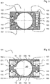
- Figure 5 is a cross-section of the motor housing 101, across the inlet 151, outlet 152 and vertical interconnection hole 173.
- Interconnection hole 173 is closed by means of a threaded peg 183.
- the illustrated example comprises eight longitudinal cooling holes having circular cross section, however it may comprise two or more longitudinal cooling holes, and the shape could be other than circular, to promote the heat evacuation from the region above and below the central bore 180.
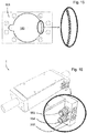
- the inlet 151, the outlet 152 and the vertical interconnection hole 173 are integrated in the flange 202 (see figure 16 ).
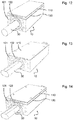
- the alternative embodiment illustrated in figure 16 comprises a modified flange 202 as explained here above, whereas the modified flange 202 further comprises a portion protruding to the side, said protruding portion having an integrated fluid cooling circuit inlet and outlet parallel to the central bore 180.
- straight tube press fittings 553, 554 can be used instead of the elbow tube press fittings.
- one or both flanges, respectively the portion of the fluid cooling circuit integrated in said flanges may be replaced by connection fittings mounted in correspondence of each longitudinal cooling holes and pipes to connect these holes to form the fluid cooling circuit.
- Figure 6 is a cross-section of the motor housing 101, across the interconnection holes 171, 172, 174 and 175. These horizontal interconnection holes are also closed by means of threaded pegs (not shown).
- the interconnection holes 171, 172, 174 and 175 may be replaced by equivalent interconnection holes or apertures 222 integrated in the flange 203, the apertures 222 having a groove-shaped form and connecting two or eventually more longitudinal cooling holes.
- all interconnections and the inlet and outlet ports can be located in the flanges 202 and 203, so that the number of machining operations to be executed with the motor housing 101 after (typically) an extrusion process are minimized.
- the cooling is improved by encompassing the entire length of the motor housing 101 and the flanges 202 and 203 with the fluid cooling circuit.
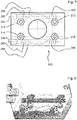
- Figure 7 depicts some details of flange 202, in particular:
- transversal holes 264 and 268 are closed by means of threaded pegs 294, 298.
- the longitudinal cooling holes 162, 163, 166, 167 of the motor housing 101 have a corresponding continuations 262, 263, 266, 267 in flange 202; said continuations are connected by the transversal holes 264, 268, as shown in figure of the at least one flange form a continuous passageway of the integrated fluid cooling circuit.
- the motor housing is preferably made of aluminum, which is an excellent heat conductor.
- the motor housing profile is preferably obtained by extrusion.
- one or more internal and/or external feature of the profile are obtained by extrusion, such as the central bore 180, the cable channel 181, the longitudinal cooling holes 161 ⁇ 168, and/or an oblong recessed channel at the outer surface of the housing (shown in Fig.9 ).
- the cross section of the longitudinal cooling holes is generally circular, however it can be optimized to follow the geometry of the central bore such as to improve heat flow to the cooling circuit.
- the flanges 202 and 203 are made of an electrically insulating material, preferably a synthetic polymer, f.i. POM, or a composite material, f.i. an epoxy glass fabric.
- the flanges are preferably manufactured by means of one or more of the following processes: injection molding, milling, boring, or additive manufacturing.
- Figure 8 is a semitransparent isometric representation of the fluid passageway created within flange 202 by means of the before mentioned connecting holes 264, 268.
- the interconnection between the longitudinal cooling holes 162, 167 on the left side and the longitudinal cooling holes 163, 166 on right side of the motor housing 101 is made within the flange 202. From figures 7 and 8 it is evident that, the integration of these transversal interconnection holes cannot be made within a motor housing having a low profile cross section as specified by the present invention, because they would interfere with the coils. Therefore the two sides of the motor housing are interconnected by means of interconnecting holes laying essentially transverse with respect to the longitudinal cooling holes of the motor housing, said interconnecting holes being located in one of the flanges.
- the invention is implemented with a tubular shaft motor having a magnetic shaft, for instance an ironless linear synchronous motor.
- a tubular shaft motor having a magnetic shaft
- the heat is generated in the copper windings of the coils, due the resistive losses.
- the invention is also applicable to other tubular shaft motors, such as iron core motors, in which the heat is generated also in the iron due to the eddy currents.
- the coils are positioned in a row in a central bore of the motor housing and fixed by means of epoxide resin. The coils must be as close as possible to the permanent magnets of the shaft for best efficiency in terms of trust. Since the arrangement of the magnetic shaft and coils is more or less unchangeable, the other features of the slider must be arranged around these core parts.
- a cooling circuit must be placed as close as possible to the heat source, but it must not interfere with the windings. Integrating a cooling circuit all around the central bore would substantially increase the construction height of the motor housing. In contrast the cooling circuit according the invention provides effective cooling while maintaining a compact construction.
- the coils may reach a temperature of about 80°C, but peak temperature can be much higher.
- the temperature difference of the cooling fluid, between inlet and outlet should be limited, preferably to less than 1°C. This means that the fluid circulation must be considerable.
- the dielectric fluid i.e. the processing fluid may be used as a coolant for the cooling circuit of the LMS.
- Said dielectric fluid is either deionized (DI) water or oil; in both cases the cooling circuit must be constituted such as not to be damaged by corrosion, dissolution, or else.
- the motor housing preferably comprises one of the following surface treatments: anodization, cataphoresis or surface coating.
- the coils are cast in the central bore 180 by means of an epoxide resin.
- the copper windings have low electrical and thermal resistance while the resin is a good insulator.
- the aluminum motor housing 101 envelops the resin epoxide casted coils, with a comparably thick resin layer to ensure electrical insulation. Heat flows from the resin embedded coils to the longitudinal cooling holes.
- the aluminum is a very good heat conductor, thus the motor housing 101 assumes a nearly uniform temperature and the heat is evacuated very effectively by means of the fluid cooling circuit.
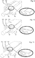
- the figures 9 to 14 are isometric representations of a LSM according the invention (the flanges are not shown) illustrating additional elements for the thermal separation of slider and machine structure.
- the motor housing 101 may comprise an recessed channel 102 at the outer surface of the housing, straight above and/or below the central bore 180, as illustrated in Fig.9 .
- said recessed channel 102 has a small depth of 0.1 to 5mm, more preferably 0.3 to 1 mm, and may be produced directly by extrusion. In this way a direct heat transfer between the solid motor housing 101 and solid structural components of the machine is avoided.
- the slider and the structural components of the machine may be separated further by adding a thermal insulating layer such as an insulating pad 110 or a plurality of insulating spacers between the mounting surfaces.
- Said insulating layer may be for instance a composite material.
- Said insulating layer may cover the entire area between motor and structural components or only the contacting area.
- a thin pad of few mm provides a substantial improvement of the thermal resistance, with no substantial loss of space.
- the two elements mentioned here above, i.e. the insertion of a recessed channel 102 and the addition of an insulating pad 110 are combined as illustrated in Fig.10 .
- the recessed channel 102 may also be arranged in the insulating pad 110, as illustrated in Fig.11 .
- Figure 12 illustrates another embodiment of the invention, with an insulating pad 130, a cooling plate 120, and a second insulating pad 110 inserted between the slider 10 and the machine structure (not shown).
- the machine structure is effectively protected from a heat immission by the LSM, because the modest residual heat which has not been captured in the primary cooling circuit is now evacuated in a secondary cooling circuit integrated in the plate 120.
- the cooling circuits of the plate 120 and of the slider 10 may be connected with each other in series, whereas the temperature controlled cooling fluid is for example first supplied to the secondary cooling circuit in the plate 120 and subsequently to the primary cooling circuit in the slider 10.
- the figures 13 and 14 show another embodiment of the invention, in which the height of slider 10 is further reduced.
- the magnetic shaft of a conventional LSM has a circular cross section.
- the present embodiments in the figures 13 and 14 show a linear shaft motor in which the magnetic shaft 30 has a reduced height of the cross section.
- Said modified magnetic shaft has a symmetric cross-section, for instance an ellipse cross-section, or a circular cross-section with two flattened sections, or a cross-section generated by two half-circles joined by straight lines.
- the perimeter of the cross section of the magnetic shaft determines the thrust.
- a magnetic shaft having f.i. an elliptic cross section has the same thrust of a magnetic shaft of same cross section perimeter having a circular cross section.
- the coils are in such embodiments wound accordingly, such to get essentially the same cross-section while keeping the necessary air gap to the magnetic shaft. In this way the slider construction height Hh is further reduced while maintaining the advantages of the inventive LSM.
- the oblong hotspot straight above and/or below the central bore is more pronounced, thus it is preferable to include one or more of the elements illustrated in conjunction with figures 9 to 12 , that is: a recessed channel, an insulation pad and/or a cooling plate.
- Figure 15 illustrates a detail of the motor housing 101, in which the surface of the central bore 180 is knurled or otherwise machined at the interfacing surface between the motor housing 101 and the resin used to embed the coils. In this way the heat surface for heat transfer is increased and heat evacuation is improved.
- the fluid cooling circuit of the inventive LSM slider ends at an outlet, which is then connected to the fluid cooling circuit of the machine tool.
- the fluid cooling circuit of the slider is extended by forming a passageway for the fluid exiting from the last longitudinal cooling hole to a circular cavity in the flange 202 (not shown), by which the fluid is conducted in the gap between the magnetic shaft and the motor coils, and across said gap to the other flange 203.
- the fluid is collected in a circular cavity in flange 203 and led to an outlet.
- the flanges 202 and 203 comprise a seal to avoid or reduce the loss of cooling fluid. Leakage fluid is conducted to a collecting tank by suitable ducts.
- the linear shaft motor comprises two supports 41, 42 holding the magnetic shaft 30 in place.
- a linear measuring system is installed between one of the flanges 202, 203 and one of the supports 41, 42.
- said linear measuring system is a laser interferometry system, as illustrated in figure 18 .
- the components of said linear measuring system are: a laser source 280 and a photodetector which are preferably mounted or integrated in one of the supports 41 or 42, and a mirror 290 which is preferably mounted or integrated in the flange 202 or 203 of the slider.
- the linear shaft motor according the invention is applicable with high precision positioning systems as used with machine tools, such as electric discharge machines, laser processing machines, additive manufacturing machines, etc.
- the LMS according the invention distinguishes itself by the compact size, in particular the low construction height, and the full integration of a fluid cooling circuit.
- a LSM motor housing according the invention can be achieved by mounting a jacket type housing around a preassembled coil assembly. This may be achieved for instance: by a fork type constitution of the jacket type housing having a horizontal slit over the entire length; or, a horizontally split two parts jacket type housing, the two halves forming a clamp around the coil assembly and being completed with the flanges.
Landscapes
- Engineering & Computer Science (AREA)
- Power Engineering (AREA)
- Physics & Mathematics (AREA)
- Chemical & Material Sciences (AREA)
- Combustion & Propulsion (AREA)
- Electromagnetism (AREA)
- Linear Motors (AREA)
- Motor Or Generator Cooling System (AREA)
Priority Applications (5)
| Application Number | Priority Date | Filing Date | Title |
|---|---|---|---|
| ES16198315T ES2883248T3 (es) | 2016-11-11 | 2016-11-11 | Motor de eje lineal |
| EP16198315.0A EP3322075B1 (de) | 2016-11-11 | 2016-11-11 | Linearer wellenmotor |
| US15/790,600 US10680495B2 (en) | 2016-11-11 | 2017-10-23 | Linear shaft motor |
| CN202310134626.0A CN115955045A (zh) | 2016-11-11 | 2017-11-10 | 直线轴马达 |
| CN201711106746.0A CN108075616A (zh) | 2016-11-11 | 2017-11-10 | 直线轴马达 |
Applications Claiming Priority (1)
| Application Number | Priority Date | Filing Date | Title |
|---|---|---|---|
| EP16198315.0A EP3322075B1 (de) | 2016-11-11 | 2016-11-11 | Linearer wellenmotor |
Publications (2)
| Publication Number | Publication Date |
|---|---|
| EP3322075A1 true EP3322075A1 (de) | 2018-05-16 |
| EP3322075B1 EP3322075B1 (de) | 2021-08-11 |
Family
ID=57391769
Family Applications (1)
| Application Number | Title | Priority Date | Filing Date |
|---|---|---|---|
| EP16198315.0A Active EP3322075B1 (de) | 2016-11-11 | 2016-11-11 | Linearer wellenmotor |
Country Status (4)
| Country | Link |
|---|---|
| US (1) | US10680495B2 (de) |
| EP (1) | EP3322075B1 (de) |
| CN (2) | CN115955045A (de) |
| ES (1) | ES2883248T3 (de) |
Cited By (1)
| Publication number | Priority date | Publication date | Assignee | Title |
|---|---|---|---|---|
| CN117477891A (zh) * | 2023-12-28 | 2024-01-30 | 燕山大学 | 一种具有开槽结构的动子外壳及磁轴式直线电机 |
Families Citing this family (5)
| Publication number | Priority date | Publication date | Assignee | Title |
|---|---|---|---|---|
| EP3264575B1 (de) * | 2016-06-28 | 2018-08-22 | Etel S. A.. | Kühlungseinrichtung für den primärteil eines eisenlosen linearmotors |
| ES3063628T3 (en) | 2018-06-06 | 2026-04-17 | Agie Charmilles Sa | Collision protection method |
| CN108900030B (zh) * | 2018-09-14 | 2024-07-16 | 苏州直为精驱控制技术有限公司 | 自冷式直线电机 |
| EP3950200B1 (de) | 2020-08-07 | 2023-05-03 | Agie Charmilles SA | Verfahren zum hochschnellen drahtschneiden |
| GB202215325D0 (en) * | 2022-10-17 | 2022-11-30 | Libertine Fpe Ltd | A housing for a linear power system |
Citations (11)
| Publication number | Priority date | Publication date | Assignee | Title |
|---|---|---|---|---|
| JPS632626A (ja) | 1986-06-20 | 1988-01-07 | Mitsubishi Electric Corp | ワイヤ放電加工装置 |
| US6040642A (en) | 1997-05-12 | 2000-03-21 | Gmc Co., Ltd. | Linear motor equipped with a stator which is easily assembled |
| US6323567B1 (en) | 1999-12-24 | 2001-11-27 | Nikon Corporation | Circulating system for shaft-type linear motors |
| CN200956544Y (zh) * | 2006-10-09 | 2007-10-03 | 伍鹏 | 自带冷却机构的无芯直线电机 |
| WO2009025162A1 (ja) * | 2007-08-21 | 2009-02-26 | Kabushiki Kaisha Yaskawa Denki | 円筒状リニアモータ電機子および円筒状リニアモータ |
| US20090195089A1 (en) * | 2008-01-31 | 2009-08-06 | Lieh-Feng Huang | Mover of a Linear Motor with an Outer Heat Radiating Housing |
| WO2010049969A1 (ja) | 2008-10-28 | 2010-05-06 | 三菱電機株式会社 | 放電加工装置 |
| CN201608596U (zh) * | 2009-12-15 | 2010-10-13 | 深圳市大族精密机电有限公司 | 用于直线电机的冷却装置和含有该冷却装置的直线电机 |
| US20110198946A1 (en) * | 2008-10-23 | 2011-08-18 | Sodick Co., Ltd. | Linear motor coil assembly with cooling device |
| CN103683797A (zh) * | 2012-09-03 | 2014-03-26 | 大银微系统股份有限公司 | 磁力相叉型的线性马达机构 |
| WO2016025975A1 (en) | 2014-08-22 | 2016-02-25 | Anca Pty Ltd | Linear motor |
Family Cites Families (19)
| Publication number | Priority date | Publication date | Assignee | Title |
|---|---|---|---|---|
| JPH06254734A (ja) * | 1993-03-02 | 1994-09-13 | Canon Inc | Xyステージ装置およびこれに用いるリニアモータ |
| US5925956A (en) * | 1995-06-30 | 1999-07-20 | Nikon Corporation | Stage construction incorporating magnetically levitated movable stage |
| GB0104212D0 (en) * | 2001-02-21 | 2001-04-11 | Johnson Electric Sa | Motor casing |
| JP2002354780A (ja) * | 2001-05-24 | 2002-12-06 | Yaskawa Electric Corp | 円筒界磁形リニアモータ |
| DE10247199A1 (de) * | 2002-10-10 | 2004-04-29 | Moog Gmbh | Elektromotor mit Flanschkühlung |
| DE20216113U1 (de) * | 2002-10-18 | 2004-03-18 | Baumüller Nürnberg GmbH | Tauchlack-beschichteter Kühl-Gehäusemantel für eine elektrische Maschine |
| JP4387181B2 (ja) * | 2003-01-22 | 2009-12-16 | Thk株式会社 | リニアモーター及び直線案内装置 |
| WO2006011614A1 (ja) * | 2004-07-25 | 2006-02-02 | Tsheatronics Co., Ltd. | 直線又は曲線移動式モータ及びその放熱器 |
| US7888827B2 (en) * | 2005-09-30 | 2011-02-15 | Thk Co., Ltd. | Linear synchronous motor and linear motor actuator |
| JP4837993B2 (ja) * | 2006-01-06 | 2011-12-14 | 住友重機械工業株式会社 | リニアモータ及びその製造方法及びこのリニアモータを用いたステージ装置 |
| US7939974B2 (en) * | 2009-07-31 | 2011-05-10 | Hiwin Mikrosystem Corp. | Movable magnet type linear motor with heat-dissipating assembly |
| US8097987B2 (en) * | 2009-07-31 | 2012-01-17 | Hiwin Mikrosystem Corp. | Movable magnet type linear motor with improved end cover assembly |
| JP5582415B2 (ja) * | 2010-08-27 | 2014-09-03 | 株式会社安川電機 | リニアモータ電機子およびそれを備えたリニアモータ |
| CN202240664U (zh) * | 2011-10-16 | 2012-05-30 | 上海杰先自动化系统有限公司 | 直线电机滑台 |
| CN202260735U (zh) * | 2011-10-16 | 2012-05-30 | 上海杰先自动化系统有限公司 | 直线电机 |
| KR101367734B1 (ko) * | 2012-09-14 | 2014-03-13 | 김홍중 | 선형 전동기 |
| CN105264752B (zh) * | 2013-05-30 | 2018-01-26 | 瑞美技术有限责任公司 | 具有液体冷却壳体的电机 |
| US10454345B2 (en) * | 2013-12-20 | 2019-10-22 | Fuji Corporation | Linear motor device |
| TWM505992U (zh) | 2014-12-25 | 2015-08-01 | Excetek Technologies Co Ltd | 降低結構誤差的放電加工機 |
-
2016
- 2016-11-11 EP EP16198315.0A patent/EP3322075B1/de active Active
- 2016-11-11 ES ES16198315T patent/ES2883248T3/es active Active
-
2017
- 2017-10-23 US US15/790,600 patent/US10680495B2/en active Active
- 2017-11-10 CN CN202310134626.0A patent/CN115955045A/zh active Pending
- 2017-11-10 CN CN201711106746.0A patent/CN108075616A/zh active Pending
Patent Citations (11)
| Publication number | Priority date | Publication date | Assignee | Title |
|---|---|---|---|---|
| JPS632626A (ja) | 1986-06-20 | 1988-01-07 | Mitsubishi Electric Corp | ワイヤ放電加工装置 |
| US6040642A (en) | 1997-05-12 | 2000-03-21 | Gmc Co., Ltd. | Linear motor equipped with a stator which is easily assembled |
| US6323567B1 (en) | 1999-12-24 | 2001-11-27 | Nikon Corporation | Circulating system for shaft-type linear motors |
| CN200956544Y (zh) * | 2006-10-09 | 2007-10-03 | 伍鹏 | 自带冷却机构的无芯直线电机 |
| WO2009025162A1 (ja) * | 2007-08-21 | 2009-02-26 | Kabushiki Kaisha Yaskawa Denki | 円筒状リニアモータ電機子および円筒状リニアモータ |
| US20090195089A1 (en) * | 2008-01-31 | 2009-08-06 | Lieh-Feng Huang | Mover of a Linear Motor with an Outer Heat Radiating Housing |
| US20110198946A1 (en) * | 2008-10-23 | 2011-08-18 | Sodick Co., Ltd. | Linear motor coil assembly with cooling device |
| WO2010049969A1 (ja) | 2008-10-28 | 2010-05-06 | 三菱電機株式会社 | 放電加工装置 |
| CN201608596U (zh) * | 2009-12-15 | 2010-10-13 | 深圳市大族精密机电有限公司 | 用于直线电机的冷却装置和含有该冷却装置的直线电机 |
| CN103683797A (zh) * | 2012-09-03 | 2014-03-26 | 大银微系统股份有限公司 | 磁力相叉型的线性马达机构 |
| WO2016025975A1 (en) | 2014-08-22 | 2016-02-25 | Anca Pty Ltd | Linear motor |
Cited By (2)
| Publication number | Priority date | Publication date | Assignee | Title |
|---|---|---|---|---|
| CN117477891A (zh) * | 2023-12-28 | 2024-01-30 | 燕山大学 | 一种具有开槽结构的动子外壳及磁轴式直线电机 |
| CN117477891B (zh) * | 2023-12-28 | 2024-03-05 | 燕山大学 | 一种具有开槽结构的动子外壳及磁轴式直线电机 |
Also Published As
| Publication number | Publication date |
|---|---|
| EP3322075B1 (de) | 2021-08-11 |
| CN115955045A (zh) | 2023-04-11 |
| US10680495B2 (en) | 2020-06-09 |
| ES2883248T3 (es) | 2021-12-07 |
| US20180138783A1 (en) | 2018-05-17 |
| CN108075616A (zh) | 2018-05-25 |
Similar Documents
| Publication | Publication Date | Title |
|---|---|---|
| US10680495B2 (en) | Linear shaft motor | |
| US11496025B2 (en) | Stator for an electric rotating machine | |
| JP4636019B2 (ja) | キャンド・リニアモータ電機子およびキャンド・リニアモータ | |
| US5864187A (en) | Fully enclosed linear motor armature | |
| KR20010092763A (ko) | 리니어 모터의 코일 조립체 및 그 제조 방법 | |
| KR102656081B1 (ko) | 전기 기계용 고정자 및 전기 기계 | |
| KR20120084800A (ko) | 전기 기기의 냉각 장치 및 방법 | |
| KR20050058328A (ko) | 코어리스 리니어 모터 | |
| CN113783323A (zh) | 一种电机定子冷却结构 | |
| US12556052B2 (en) | Direct slot cooling in electric machines | |
| Yao et al. | In-slot cooling for high power density electric motor with encapsulation channels | |
| CN114268193B (zh) | 一种车辆、电驱动系统及其加工方法 | |
| US6946761B2 (en) | Actuator coil cooling system | |
| JP2004312877A (ja) | キャンド・リニアモータ電機子およびキャンド・リニアモータ | |
| US20090322168A1 (en) | Stator of a turbo generator | |
| WO2023047015A1 (en) | A winding system | |
| EP3826152A1 (de) | Flüssigkeitsgekühlte kernanordnung für linearmotoren und linearmotor mit einer solchen kernanordnung | |
| US12451753B2 (en) | Electric machine with directly cooled windings | |
| JP7014344B1 (ja) | モータ及びモータ装置 | |
| WO2020031657A1 (ja) | リニアモータ機構および二軸ステージ | |
| CN121173018A (zh) | 一种具有直接冷却流道结构的外转子电机定子 | |
| CN121689674A (zh) | 全包围液冷直线电机定子装置 | |
| CN120601693A (zh) | 一种电机定子的散热结构和电机 | |
| CN107911004A (zh) | 一种永磁直线电机 | |
| HK40042009A (en) | Cooling mechanism of a stator for an axial flux machine |
Legal Events
| Date | Code | Title | Description |
|---|---|---|---|
| PUAI | Public reference made under article 153(3) epc to a published international application that has entered the european phase |
Free format text: ORIGINAL CODE: 0009012 |
|
| STAA | Information on the status of an ep patent application or granted ep patent |
Free format text: STATUS: THE APPLICATION HAS BEEN PUBLISHED |
|
| AK | Designated contracting states |
Kind code of ref document: A1 Designated state(s): AL AT BE BG CH CY CZ DE DK EE ES FI FR GB GR HR HU IE IS IT LI LT LU LV MC MK MT NL NO PL PT RO RS SE SI SK SM TR |
|
| AX | Request for extension of the european patent |
Extension state: BA ME |
|
| STAA | Information on the status of an ep patent application or granted ep patent |
Free format text: STATUS: REQUEST FOR EXAMINATION WAS MADE |
|
| 17P | Request for examination filed |
Effective date: 20180926 |
|
| RBV | Designated contracting states (corrected) |
Designated state(s): AL AT BE BG CH CY CZ DE DK EE ES FI FR GB GR HR HU IE IS IT LI LT LU LV MC MK MT NL NO PL PT RO RS SE SI SK SM TR |
|
| STAA | Information on the status of an ep patent application or granted ep patent |
Free format text: STATUS: EXAMINATION IS IN PROGRESS |
|
| 17Q | First examination report despatched |
Effective date: 20181203 |
|
| RIC1 | Information provided on ipc code assigned before grant |
Ipc: H02K 41/03 20060101AFI20190404BHEP Ipc: H02K 5/20 20060101ALN20190404BHEP Ipc: H02K 9/19 20060101ALN20190404BHEP |
|
| RIC1 | Information provided on ipc code assigned before grant |
Ipc: H02K 41/03 20060101AFI20190415BHEP Ipc: H02K 5/20 20060101ALN20190415BHEP Ipc: H02K 9/19 20060101ALN20190415BHEP |
|
| GRAP | Despatch of communication of intention to grant a patent |
Free format text: ORIGINAL CODE: EPIDOSNIGR1 |
|
| STAA | Information on the status of an ep patent application or granted ep patent |
Free format text: STATUS: GRANT OF PATENT IS INTENDED |
|
| RIC1 | Information provided on ipc code assigned before grant |
Ipc: H02K 5/20 20060101ALN20210323BHEP Ipc: H02K 9/19 20060101ALN20210323BHEP Ipc: H02K 41/03 20060101AFI20210323BHEP |
|
| RIC1 | Information provided on ipc code assigned before grant |
Ipc: H02K 5/20 20060101ALN20210331BHEP Ipc: H02K 9/19 20060101ALN20210331BHEP Ipc: H02K 41/03 20060101AFI20210331BHEP |
|
| INTG | Intention to grant announced |
Effective date: 20210421 |
|
| GRAS | Grant fee paid |
Free format text: ORIGINAL CODE: EPIDOSNIGR3 |
|
| GRAA | (expected) grant |
Free format text: ORIGINAL CODE: 0009210 |
|
| STAA | Information on the status of an ep patent application or granted ep patent |
Free format text: STATUS: THE PATENT HAS BEEN GRANTED |
|
| AK | Designated contracting states |
Kind code of ref document: B1 Designated state(s): AL AT BE BG CH CY CZ DE DK EE ES FI FR GB GR HR HU IE IS IT LI LT LU LV MC MK MT NL NO PL PT RO RS SE SI SK SM TR |
|
| REG | Reference to a national code |
Ref country code: CH Ref legal event code: EP |
|
| REG | Reference to a national code |
Ref country code: DE Ref legal event code: R096 Ref document number: 602016061916 Country of ref document: DE |
|
| REG | Reference to a national code |
Ref country code: IE Ref legal event code: FG4D Ref country code: AT Ref legal event code: REF Ref document number: 1420410 Country of ref document: AT Kind code of ref document: T Effective date: 20210915 |
|
| REG | Reference to a national code |
Ref country code: ES Ref legal event code: FG2A Ref document number: 2883248 Country of ref document: ES Kind code of ref document: T3 Effective date: 20211207 |
|
| REG | Reference to a national code |
Ref country code: LT Ref legal event code: MG9D |
|
| REG | Reference to a national code |
Ref country code: NL Ref legal event code: MP Effective date: 20210811 |
|
| PG25 | Lapsed in a contracting state [announced via postgrant information from national office to epo] |
Ref country code: FI Free format text: LAPSE BECAUSE OF FAILURE TO SUBMIT A TRANSLATION OF THE DESCRIPTION OR TO PAY THE FEE WITHIN THE PRESCRIBED TIME-LIMIT Effective date: 20210811 Ref country code: NO Free format text: LAPSE BECAUSE OF FAILURE TO SUBMIT A TRANSLATION OF THE DESCRIPTION OR TO PAY THE FEE WITHIN THE PRESCRIBED TIME-LIMIT Effective date: 20211111 Ref country code: PT Free format text: LAPSE BECAUSE OF FAILURE TO SUBMIT A TRANSLATION OF THE DESCRIPTION OR TO PAY THE FEE WITHIN THE PRESCRIBED TIME-LIMIT Effective date: 20211213 Ref country code: LT Free format text: LAPSE BECAUSE OF FAILURE TO SUBMIT A TRANSLATION OF THE DESCRIPTION OR TO PAY THE FEE WITHIN THE PRESCRIBED TIME-LIMIT Effective date: 20210811 Ref country code: BG Free format text: LAPSE BECAUSE OF FAILURE TO SUBMIT A TRANSLATION OF THE DESCRIPTION OR TO PAY THE FEE WITHIN THE PRESCRIBED TIME-LIMIT Effective date: 20211111 Ref country code: HR Free format text: LAPSE BECAUSE OF FAILURE TO SUBMIT A TRANSLATION OF THE DESCRIPTION OR TO PAY THE FEE WITHIN THE PRESCRIBED TIME-LIMIT Effective date: 20210811 Ref country code: SE Free format text: LAPSE BECAUSE OF FAILURE TO SUBMIT A TRANSLATION OF THE DESCRIPTION OR TO PAY THE FEE WITHIN THE PRESCRIBED TIME-LIMIT Effective date: 20210811 Ref country code: RS Free format text: LAPSE BECAUSE OF FAILURE TO SUBMIT A TRANSLATION OF THE DESCRIPTION OR TO PAY THE FEE WITHIN THE PRESCRIBED TIME-LIMIT Effective date: 20210811 |
|
| REG | Reference to a national code |
Ref country code: AT Ref legal event code: UEP Ref document number: 1420410 Country of ref document: AT Kind code of ref document: T Effective date: 20210811 |
|
| PG25 | Lapsed in a contracting state [announced via postgrant information from national office to epo] |
Ref country code: PL Free format text: LAPSE BECAUSE OF FAILURE TO SUBMIT A TRANSLATION OF THE DESCRIPTION OR TO PAY THE FEE WITHIN THE PRESCRIBED TIME-LIMIT Effective date: 20210811 Ref country code: LV Free format text: LAPSE BECAUSE OF FAILURE TO SUBMIT A TRANSLATION OF THE DESCRIPTION OR TO PAY THE FEE WITHIN THE PRESCRIBED TIME-LIMIT Effective date: 20210811 Ref country code: GR Free format text: LAPSE BECAUSE OF FAILURE TO SUBMIT A TRANSLATION OF THE DESCRIPTION OR TO PAY THE FEE WITHIN THE PRESCRIBED TIME-LIMIT Effective date: 20211112 |
|
| PG25 | Lapsed in a contracting state [announced via postgrant information from national office to epo] |
Ref country code: NL Free format text: LAPSE BECAUSE OF FAILURE TO SUBMIT A TRANSLATION OF THE DESCRIPTION OR TO PAY THE FEE WITHIN THE PRESCRIBED TIME-LIMIT Effective date: 20210811 |
|
| PG25 | Lapsed in a contracting state [announced via postgrant information from national office to epo] |
Ref country code: DK Free format text: LAPSE BECAUSE OF FAILURE TO SUBMIT A TRANSLATION OF THE DESCRIPTION OR TO PAY THE FEE WITHIN THE PRESCRIBED TIME-LIMIT Effective date: 20210811 |
|
| REG | Reference to a national code |
Ref country code: DE Ref legal event code: R097 Ref document number: 602016061916 Country of ref document: DE |
|
| PG25 | Lapsed in a contracting state [announced via postgrant information from national office to epo] |
Ref country code: SM Free format text: LAPSE BECAUSE OF FAILURE TO SUBMIT A TRANSLATION OF THE DESCRIPTION OR TO PAY THE FEE WITHIN THE PRESCRIBED TIME-LIMIT Effective date: 20210811 Ref country code: SK Free format text: LAPSE BECAUSE OF FAILURE TO SUBMIT A TRANSLATION OF THE DESCRIPTION OR TO PAY THE FEE WITHIN THE PRESCRIBED TIME-LIMIT Effective date: 20210811 Ref country code: RO Free format text: LAPSE BECAUSE OF FAILURE TO SUBMIT A TRANSLATION OF THE DESCRIPTION OR TO PAY THE FEE WITHIN THE PRESCRIBED TIME-LIMIT Effective date: 20210811 Ref country code: EE Free format text: LAPSE BECAUSE OF FAILURE TO SUBMIT A TRANSLATION OF THE DESCRIPTION OR TO PAY THE FEE WITHIN THE PRESCRIBED TIME-LIMIT Effective date: 20210811 Ref country code: CZ Free format text: LAPSE BECAUSE OF FAILURE TO SUBMIT A TRANSLATION OF THE DESCRIPTION OR TO PAY THE FEE WITHIN THE PRESCRIBED TIME-LIMIT Effective date: 20210811 Ref country code: AL Free format text: LAPSE BECAUSE OF FAILURE TO SUBMIT A TRANSLATION OF THE DESCRIPTION OR TO PAY THE FEE WITHIN THE PRESCRIBED TIME-LIMIT Effective date: 20210811 |
|
| PLBE | No opposition filed within time limit |
Free format text: ORIGINAL CODE: 0009261 |
|
| STAA | Information on the status of an ep patent application or granted ep patent |
Free format text: STATUS: NO OPPOSITION FILED WITHIN TIME LIMIT |
|
| PG25 | Lapsed in a contracting state [announced via postgrant information from national office to epo] |
Ref country code: MC Free format text: LAPSE BECAUSE OF FAILURE TO SUBMIT A TRANSLATION OF THE DESCRIPTION OR TO PAY THE FEE WITHIN THE PRESCRIBED TIME-LIMIT Effective date: 20210811 |
|
| 26N | No opposition filed |
Effective date: 20220512 |
|
| PG25 | Lapsed in a contracting state [announced via postgrant information from national office to epo] |
Ref country code: LU Free format text: LAPSE BECAUSE OF NON-PAYMENT OF DUE FEES Effective date: 20211111 Ref country code: BE Free format text: LAPSE BECAUSE OF NON-PAYMENT OF DUE FEES Effective date: 20211130 |
|
| REG | Reference to a national code |
Ref country code: BE Ref legal event code: MM Effective date: 20211130 |
|
| PG25 | Lapsed in a contracting state [announced via postgrant information from national office to epo] |
Ref country code: SI Free format text: LAPSE BECAUSE OF FAILURE TO SUBMIT A TRANSLATION OF THE DESCRIPTION OR TO PAY THE FEE WITHIN THE PRESCRIBED TIME-LIMIT Effective date: 20210811 |
|
| PG25 | Lapsed in a contracting state [announced via postgrant information from national office to epo] |
Ref country code: IE Free format text: LAPSE BECAUSE OF NON-PAYMENT OF DUE FEES Effective date: 20211111 |
|
| PG25 | Lapsed in a contracting state [announced via postgrant information from national office to epo] |
Ref country code: HU Free format text: LAPSE BECAUSE OF FAILURE TO SUBMIT A TRANSLATION OF THE DESCRIPTION OR TO PAY THE FEE WITHIN THE PRESCRIBED TIME-LIMIT; INVALID AB INITIO Effective date: 20161111 |
|
| PG25 | Lapsed in a contracting state [announced via postgrant information from national office to epo] |
Ref country code: CY Free format text: LAPSE BECAUSE OF FAILURE TO SUBMIT A TRANSLATION OF THE DESCRIPTION OR TO PAY THE FEE WITHIN THE PRESCRIBED TIME-LIMIT Effective date: 20210811 |
|
| P01 | Opt-out of the competence of the unified patent court (upc) registered |
Effective date: 20230529 |
|
| PG25 | Lapsed in a contracting state [announced via postgrant information from national office to epo] |
Ref country code: MK Free format text: LAPSE BECAUSE OF FAILURE TO SUBMIT A TRANSLATION OF THE DESCRIPTION OR TO PAY THE FEE WITHIN THE PRESCRIBED TIME-LIMIT Effective date: 20210811 |
|
| PG25 | Lapsed in a contracting state [announced via postgrant information from national office to epo] |
Ref country code: TR Free format text: LAPSE BECAUSE OF FAILURE TO SUBMIT A TRANSLATION OF THE DESCRIPTION OR TO PAY THE FEE WITHIN THE PRESCRIBED TIME-LIMIT Effective date: 20210811 |
|
| PG25 | Lapsed in a contracting state [announced via postgrant information from national office to epo] |
Ref country code: MT Free format text: LAPSE BECAUSE OF FAILURE TO SUBMIT A TRANSLATION OF THE DESCRIPTION OR TO PAY THE FEE WITHIN THE PRESCRIBED TIME-LIMIT Effective date: 20210811 |
|
| REG | Reference to a national code |
Ref country code: CH Ref legal event code: U11 Free format text: ST27 STATUS EVENT CODE: U-0-0-U10-U11 (AS PROVIDED BY THE NATIONAL OFFICE) Effective date: 20251201 |
|
| PGFP | Annual fee paid to national office [announced via postgrant information from national office to epo] |
Ref country code: DE Payment date: 20251119 Year of fee payment: 10 |
|
| PGFP | Annual fee paid to national office [announced via postgrant information from national office to epo] |
Ref country code: GB Payment date: 20251121 Year of fee payment: 10 |
|
| PGFP | Annual fee paid to national office [announced via postgrant information from national office to epo] |
Ref country code: AT Payment date: 20251120 Year of fee payment: 10 |
|
| PGFP | Annual fee paid to national office [announced via postgrant information from national office to epo] |
Ref country code: IT Payment date: 20251125 Year of fee payment: 10 |
|
| PGFP | Annual fee paid to national office [announced via postgrant information from national office to epo] |
Ref country code: FR Payment date: 20251126 Year of fee payment: 10 |
|
| PGFP | Annual fee paid to national office [announced via postgrant information from national office to epo] |
Ref country code: CH Payment date: 20251201 Year of fee payment: 10 |
|
| PGFP | Annual fee paid to national office [announced via postgrant information from national office to epo] |
Ref country code: ES Payment date: 20251229 Year of fee payment: 10 |