EP3324009A1 - Dampfturbinenanlage - Google Patents
Dampfturbinenanlage Download PDFInfo
- Publication number
- EP3324009A1 EP3324009A1 EP16836947.8A EP16836947A EP3324009A1 EP 3324009 A1 EP3324009 A1 EP 3324009A1 EP 16836947 A EP16836947 A EP 16836947A EP 3324009 A1 EP3324009 A1 EP 3324009A1
- Authority
- EP
- European Patent Office
- Prior art keywords
- low pressure
- steam
- turbine
- disposed
- pressure turbine
- Prior art date
- Legal status (The legal status is an assumption and is not a legal conclusion. Google has not performed a legal analysis and makes no representation as to the accuracy of the status listed.)
- Granted
Links
Images


Classifications
-
- F—MECHANICAL ENGINEERING; LIGHTING; HEATING; WEAPONS; BLASTING
- F01—MACHINES OR ENGINES IN GENERAL; ENGINE PLANTS IN GENERAL; STEAM ENGINES
- F01K—STEAM ENGINE PLANTS; STEAM ACCUMULATORS; ENGINE PLANTS NOT OTHERWISE PROVIDED FOR; ENGINES USING SPECIAL WORKING FLUIDS OR CYCLES
- F01K7/00—Steam engine plants characterised by the use of specific types of engine; Plants or engines characterised by their use of special steam systems, cycles or processes; Control means specially adapted for such systems, cycles or processes; Use of withdrawn or exhaust steam for feed-water heating
- F01K7/16—Steam engine plants characterised by the use of specific types of engine; Plants or engines characterised by their use of special steam systems, cycles or processes; Control means specially adapted for such systems, cycles or processes; Use of withdrawn or exhaust steam for feed-water heating the engines being only of turbine type
- F01K7/22—Steam engine plants characterised by the use of specific types of engine; Plants or engines characterised by their use of special steam systems, cycles or processes; Control means specially adapted for such systems, cycles or processes; Use of withdrawn or exhaust steam for feed-water heating the engines being only of turbine type the turbines having inter-stage steam heating
- F01K7/223—Inter-stage moisture separation
-
- F—MECHANICAL ENGINEERING; LIGHTING; HEATING; WEAPONS; BLASTING
- F01—MACHINES OR ENGINES IN GENERAL; ENGINE PLANTS IN GENERAL; STEAM ENGINES
- F01D—NON-POSITIVE DISPLACEMENT MACHINES OR ENGINES, e.g. STEAM TURBINES
- F01D25/00—Component parts, details, or accessories, not provided for in, or of interest apart from, other groups
- F01D25/32—Collecting of condensation water; Drainage ; Removing solid particles
-
- F—MECHANICAL ENGINEERING; LIGHTING; HEATING; WEAPONS; BLASTING
- F01—MACHINES OR ENGINES IN GENERAL; ENGINE PLANTS IN GENERAL; STEAM ENGINES
- F01K—STEAM ENGINE PLANTS; STEAM ACCUMULATORS; ENGINE PLANTS NOT OTHERWISE PROVIDED FOR; ENGINES USING SPECIAL WORKING FLUIDS OR CYCLES
- F01K7/00—Steam engine plants characterised by the use of specific types of engine; Plants or engines characterised by their use of special steam systems, cycles or processes; Control means specially adapted for such systems, cycles or processes; Use of withdrawn or exhaust steam for feed-water heating
- F01K7/34—Steam engine plants characterised by the use of specific types of engine; Plants or engines characterised by their use of special steam systems, cycles or processes; Control means specially adapted for such systems, cycles or processes; Use of withdrawn or exhaust steam for feed-water heating the engines being of extraction or non-condensing type; Use of steam for feed-water heating
- F01K7/38—Steam engine plants characterised by the use of specific types of engine; Plants or engines characterised by their use of special steam systems, cycles or processes; Control means specially adapted for such systems, cycles or processes; Use of withdrawn or exhaust steam for feed-water heating the engines being of extraction or non-condensing type; Use of steam for feed-water heating the engines being of turbine type
-
- F—MECHANICAL ENGINEERING; LIGHTING; HEATING; WEAPONS; BLASTING
- F01—MACHINES OR ENGINES IN GENERAL; ENGINE PLANTS IN GENERAL; STEAM ENGINES
- F01K—STEAM ENGINE PLANTS; STEAM ACCUMULATORS; ENGINE PLANTS NOT OTHERWISE PROVIDED FOR; ENGINES USING SPECIAL WORKING FLUIDS OR CYCLES
- F01K13/00—General layout or general methods of operation of complete plants
Definitions
- the present invention relates to a steam turbine plant used for nuclear power plants, thermal power plants, and the like.
- a nuclear power plant sends steam generated by a steam generator to a steam turbine, and drives a connected generator to generate electricity.
- a steam turbine includes a high pressure turbine and a low pressure turbine, and steam used in the high pressure turbine is sent to the low pressure turbine after the moisture is removed by a moisture separating heater and the steam is heated.
- the steam used in the steam turbine is cooled by a condenser to become condensate, and the condensate is returned to the steam generator after being heated by a low pressure feed water heater, a high pressure feed water heater or the like.
- a steam turbine high pressure turbine, intermediate pressure turbine, and low pressure turbine
- generator high pressure moisture separating heater, low pressure moisture separating heater, and the like
- Patent Literature 1 An example of such a steam turbine plant is described in the following Patent Literature 1.
- Patent Literature 1 JP S62-218606 A
- An object of the present invention is to solve the above-mentioned problem, and to provide a steam turbine plant that achieves simplification of the structure and reduction of equipment cost.
- a steam turbine plant comprising: a high and intermediate pressure turbine having a high pressure turbine unit at one end in an axial direction and an intermediate pressure turbine unit at the other end; at least one low pressure turbine disposed coaxially with the high and intermediate pressure turbine; at least one high pressure moisture separator arranged to remove moisture from steam from the high pressure turbine unit and send the steam to the intermediate pressure turbine unit; and at least one low pressure moisture separator arranged to remove the moisture from the steam from the intermediate pressure turbine unit and send the steam to the at least one low pressure turbine, wherein the at least one high pressure moisture separator and the at least one low pressure moisture separator are each disposed symmetrically with respect to a center line along the axial direction of the high and intermediate pressure turbine.
- the high pressure moisture separator and the low pressure moisture separator each symmetrically with respect to the center line of the high and intermediate pressure turbine, the high pressure moisture separator can be disposed in the vicinity of the high and intermediate pressure turbine or the low pressure turbine.
- a pipe length is shortened, the structure can be simplified, the equipment cost can be reduced, and the turbine building can also be downsized.
- the steam turbine plant comprises the two high pressure moisture separators and the two low pressure moisture separators, wherein the two high pressure moisture separators are disposed on both sides of the high and intermediate pressure turbine, the two low pressure moisture separators are disposed on both sides of the high and intermediate pressure turbine, and the two high pressure moisture separators and the two low pressure moisture separators are disposed in series along the axial direction.
- the at least one high pressure moisture separator is disposed on a side opposite to the at least one low pressure turbine in the axial direction of the high and intermediate pressure turbine, and the at least one low pressure moisture separator is disposed on a low pressure turbine side in the axial direction of the high and intermediate pressure turbine.
- the high pressure moisture separator is disposed in the vicinity of the high and intermediate pressure turbine, and the low pressure moisture separator is disposed in the vicinity of the low pressure turbine.
- the steam turbine plant comprises the one high pressure moisture separator and the two low pressure moisture separators, wherein the one high pressure moisture separator is disposed along the center line on a side opposite to the at least one low pressure turbine in the axial direction of the high and intermediate pressure turbine, and the two low pressure moisture separators are disposed on both sides of the high and intermediate pressure turbine.
- the at least one high pressure moisture separator is disposed along a direction intersecting the axial direction.
- the high pressure moisture separator in a direction intersecting the high and intermediate pressure turbine and the low pressure turbine, the space in the axial direction can be effectively utilized, thereby downsizing the turbine building.
- the at least one high pressure moisture separator and the at least one low pressure moisture separator are disposed on one of a first floor on which the high and intermediate pressure turbine and the at least one low pressure turbine are disposed and a second floor a floor level of which is different from that of the first floor.
- the at least one high pressure moisture separator is disposed on one of a first floor on which the high and intermediate pressure turbine and the at least one low pressure turbine are disposed and a second floor a floor level of which is different from that of the first floor, and the at least one low pressure moisture separator is disposed on another floor of the first floor and the second floor.
- the at least one high pressure moisture separator is a high pressure moisture separating heater.
- thermal efficiency of the turbine plant can be further improved.
- the high pressure moisture separator and the low pressure moisture separator are each disposed symmetrically with respect to the center line along the axial direction of the high and intermediate pressure turbine, the structure can be simplified, and the equipment cost can be reduced.
- FIG. 1 is a schematic configuration diagram showing a nuclear power plant according to a first embodiment.
- a nuclear reactor of the first embodiment is a pressurized water reactor (PWR) that uses light water as nuclear reactor coolant and neutron moderator, produces high temperature and high pressure water without boiling over the whole reactor core, sends this high temperature and high pressure water to the steam generator to generate steam by heat exchange, and sends this steam to a turbine generator to generate electricity.
- PWR pressurized water reactor
- a reactor containment 11 has a pressurized water reactor 12 and a steam generator 13 therein, and the pressurized water reactor 12 and the steam generator 13 are connected via pipes 14, 15.
- a pressurizer 16 is provided in the pipe 14, and a primary cooling water pump 17 is provided in the pipe 15.
- light water is used as moderator and primary cooling water (coolant).
- a primary cooling system is controlled by the pressurizer 16 so as to maintain a high pressure state of about 150 to 160 atm.
- the light water is heated as primary cooling water by low enriched uranium or MOX as fuel (nuclear fuel), and the high temperature primary cooling water is sent to the steam generator 13 through the pipe 14 while being maintained at a predetermined high pressure by the pressurizer 16.
- heat exchange is performed between the high temperature and high pressure primary cooling water and secondary cooling water, and the cooled primary cooling water is returned to the pressurized water reactor 12 through the pipe 15.
- the steam generator 13 is connected to a steam turbine 19 via a pipe 18, and a main steam isolation valve 20 is provided in the pipe 18.
- the steam turbine 19 has a high and intermediate pressure turbine 21 and two low pressure turbines 22 and 23, and a generator 24 is connected coaxially.
- the high and intermediate pressure turbine 21 has a high pressure turbine unit 25 and an intermediate pressure turbine unit 26, and a high pressure moisture separating heater 27 is provided between the high pressure turbine unit 25 and the intermediate pressure turbine unit 26. Furthermore, a low pressure moisture separating heater 28 is provided between the high and intermediate pressure turbine 21 (intermediate pressure turbine unit 26) and the low pressure turbines 22 and 23.
- the pipe 18 from the steam generator 13 is connected to an inlet portion of the high pressure turbine unit 25, a steam pipe 29 is connected from an outlet portion of the high pressure turbine unit 25 to the inlet portion of the high pressure moisture separating heater 27, and a steam pipe 30 is connected from an outlet portion of the high pressure moisture separating heater 27 to an inlet portion of the intermediate pressure turbine unit 26. Furthermore, a steam pipe 31 is connected from an outlet portion of the intermediate pressure turbine unit 26 to an inlet portion of the low pressure moisture separating heater 28, and a steam pipe 32 is connected from an outlet portion of the low pressure moisture separating heater 28 to respective inlet portions of the low pressure turbines 22 and 23.
- condensers 33 and 34 are provided below the low pressure turbines 22 and 23.
- the condensers 33 and 34 cool steam used in the low pressure turbines 22 and 23 with cooling water and condense the steam to make condensate.
- Seawater is used as the cooling water, and the condensers 33 and 34 are connected to an intake pipe 35 and a drain pipe 36 for supplying and discharging the cooling water.
- the intake pipe 35 has a circulating water pump 37, and one end portion thereof is disposed in the sea together with the drain pipe 36.
- a pipe 38 is connected to the condensers 33 and 34, and a condensate pump 39, a gland condenser 40, a condensate demineralizer 41, a condensate booster pump 42, and low pressure feed water heaters 43, 44, 45, and 46 are provided in this pipe 38 in order along the flow direction of the condensate.
- the first low pressure feed water heater 43 and the second low pressure feed water heater 44 are provided in the condensers 33 and 34, and the condensate is heated by the steam used in the low pressure turbines 22 and 23.
- the third low pressure feed water heater 45 and the fourth low pressure feed water heater 46 are provided outside the condensers 33 and 34. In the third low pressure feed water heater 45, the condensate is heated by the steam extracted from the low pressure turbines 22 and 23, and in the fourth low pressure feed water heater 46, the condensate is heated by the steam exhausted from the intermediate pressure turbine unit 26.
- the pipe 38 is provided with a deaerator 47, a main feed water pump 48, a high pressure feed water heater 49, and a main feed water control valve 50 in this order along the flow direction of the condensate.
- the steam generated by performing the heat exchange with the high temperature and high pressure primary cooling water in the steam generator 13 is sent to the steam turbine 19 through the pipe 18, the high and intermediate pressure turbine 21 and each of the low pressure turbines 22 and 23 are operated to obtain rotational force, and the generator 24 is driven by this rotational force to generate electricity.
- the steam from the steam generator 13 drives the high pressure turbine unit 25
- the moisture contained in the steam is removed by the high pressure moisture separating heater 27, and the steam is heated to drive the intermediate pressure turbine unit 26.
- the steam that has driven the intermediate pressure turbine unit 26 drives the low pressure turbines 22 and 23 after the moisture contained in the steam is removed by the low pressure moisture separating heater 28 and the steam is heated.
- the steam that has driven the low pressure turbines 22 and 23 is cooled by the seawater in the condensers 33, 34 to become condensate, flows through the pipe 38 by the condensate pump 39, and is returned through the gland condenser 40, the condensate demineralizer 41, the low pressure feed water heaters 43, 44, 45, and 46, the deaerator 47, the high pressure feed water heater 49, and the like to the steam generator 13.
- FIG. 2 is a schematic diagram showing the flow of the condensate and the steam in a steam turbine plant of the first embodiment.
- the steam pipe 31 from the outlet portion of the intermediate pressure turbine unit 26 to the inlet portion of the low pressure moisture separating heater 28 is connected to a base end portion of a steam branch pipe 51 branched from a middle portion of the steam pipe 31, and a distal end portion of the steam branch pipe 51 is connected to the fourth low pressure feed water heater 46.
- a distal end portion of a bleed air pipe 52 from the low pressure turbines 22 and 23 is connected to the third low pressure feed water heater 45. Therefore, the third low pressure feed water heater 45 heats the condensate with the steam extracted from the low pressure turbines 22 and 23, and the fourth low pressure feed water heater 46 heats the condensate with the steam exhausted from the intermediate pressure turbine unit 26.
- drain water
- a drain pipe 53 is connected from the fourth low pressure feed water heater 46 to the third low pressure feed water heater 45
- a drain pipe 54 is connected from the third low pressure feed water heater 45 to the second low pressure feed water heater 44
- a drain pipe 55 is connected from the second low pressure feed water heater 44 to the first low pressure feed water heater 43.
- a drain pipe 56 is connected from the first low pressure feed water heater 43 to a portion in the pipe 38 between the first low pressure feed water heater 43 and the second low pressure feed water heater 44, and a drain pump 57 is provided in the drain pipe 56.
- the high pressure moisture separating heater 27, the low pressure moisture separating heater 28, and the like are disposed efficiently in the limited space with respect to the steam turbine 19.
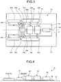
- FIG. 3 is a plan view showing an arrangement of the steam turbine plant of the first embodiment
- FIG. 4 is a front view showing an arrangement of the steam turbine plant.
- the steam turbine plant of the first embodiment includes the high and intermediate pressure turbine 21, the low pressure turbines 22 and 23, the generator 24, the high pressure moisture separating heater 27 (27a and 27b), and the low pressure moisture separating heater 28 (28a and 28b).
- a turbine building (not shown) includes a plurality of floors.
- a foundation 62 is laid at a center of a predetermined floor (first floor) 61, and on the foundation 62, the high and intermediate pressure turbine 21, the two low pressure turbines 22 and 23, and the generator 24 are installed coaxially along the axial direction C.
- the low pressure moisture separating heater 28 includes two low pressure moisture separating heaters 28a and 28b, and they are disposed on the floor 61 so as to be positioned on both sides of the high and intermediate pressure turbine 21 in a width direction (vertical direction in FIG. 3 ).
- Each of the low pressure moisture separating heaters 28a and 28b is disposed at a predetermined distance from the high and intermediate pressure turbine 21 and each of the low pressure turbines 22, 23, and is arranged parallel to the axial direction C.
- Each of the low pressure moisture separating heaters 28a and 28b removes the moisture from the steam exhausted from the high and intermediate pressure turbine 21 and sends the steam to the low pressure turbines 22 and 23.
- Two steam pipes 31a and 31b extend from the outlet portion of the intermediate pressure turbine unit 26 (see FIG.
- each of the low pressure moisture separating heaters 28a and 28b is provided with a group of heat transfer tubes as heating sources for heating the steam, in which the steam from the steam generator 13 circulates.
- the high pressure moisture separating heater 27 includes two high pressure moisture separating heaters 27a and 27b, and they are disposed on the floor 61 so as to be positioned on both sides of the high and intermediate pressure turbine 21 in the width direction (vertical direction in FIG. 3 ).
- Each of the high pressure moisture separating heaters 27a and 27b removes the moisture from the steam exhausted from the high pressure turbine unit 25 and sends the steam to the intermediate pressure turbine unit 26.
- Steam pipes 29a and 29b extend from the outlet portion of the high pressure turbine unit 25 (see FIG. 2 ), and distal end portions thereof are respectively connected to the inlet portions of the high pressure moisture separating heaters 27a and 27b.
- Steam pipes 30a and 30b are connected to the inlet portion of the intermediate pressure turbine unit 26 from the outlet portions of the high pressure moisture separating heaters 27a and 27b.
- each of the high pressure moisture separating heaters 27a and 27b is provided with a group of heat transfer tubes as heating sources for heating the steam, in which the steam from the steam generator 13 circulates.
- the high and intermediate pressure turbine 21, the low pressure turbines 22 and 23, the generator 24, the high pressure moisture separating heater 27 (27a and 27b), and the low pressure moisture separating heater 28 (28a and 28b) are disposed on the same floor 61.
- the high pressure moisture separating heaters 27a and 27b and the low pressure moisture separating heaters 28a and 28b are disposed on both sides in a horizontal direction orthogonal to the axial direction C of the high and intermediate pressure turbine 21 and the low pressure turbines 22 and 23, symmetrically with respect to the center line along the axial direction C.
- the two high pressure moisture separating heaters 27a and 27b are disposed on both sides of the high and intermediate pressure turbine 21 in parallel with the axial direction C.
- the two low pressure moisture separating heaters 28a and 28b are disposed on both sides of the high and intermediate pressure turbine 21 and the low pressure turbines 22 and 23 in parallel with the axial direction C.
- the high pressure moisture separating heaters 27a and 27b are disposed on a side opposite to the low pressure turbines 22 and 23 in the axial direction C of the high and intermediate pressure turbine 21, and the low pressure moisture separating heaters 28a and 28b are disposed on a side of the low pressure turbines 22 and 23 in the axial direction C of the high and intermediate pressure turbine 21.
- the high pressure moisture separating heaters 27a and 27b and the low pressure moisture separating heaters 28a and 28b are disposed in series along the axial direction C.
- the deaerator 47 (see FIG. 2 ) is disposed on the floor 61 on one side in the axial direction C of the high and intermediate pressure turbine 21, along a direction intersecting the axial direction C of the high and intermediate pressure turbine 21.
- the deaerator 47 removes impurities such as dissolved oxygen and uncondensed gas (ammonia gas) in the condensate (feed water) from the fourth low pressure feed water heater 46 (see FIG. 2 ).
- the high pressure moisture separating heaters 27a and 27b are disposed between the high and intermediate pressure turbine 21 and the deaerator 47.
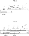
- FIG. 5 and FIG. 6 are front views each showing another arrangement of the steam turbine plant.
- a floor (second floor) 63 is provided below the floor 61.
- the high pressure moisture separating heaters 27a (27b) are disposed on the lower floor 63 different from the floor 61 on which the high and intermediate pressure turbine 21, the low pressure turbines 22 and 23, the low pressure moisture separating heater 28 (28a and 28b), and the like are installed.
- the high pressure moisture separating heaters 27a (27b) are disposed on both sides in the horizontal direction orthogonal to the axial direction C, symmetrically with respect to the center line along the axial direction C so as to be parallel with the axial direction C.
- the deaerator 47 is disposed on the floor 61 on one side in the axial direction C of the high and intermediate pressure turbine 21, along a direction intersecting the axial direction C of the high and intermediate pressure turbine 21.
- the high pressure moisture separating heaters 27a (27b) and the low pressure moisture separating heaters 28a (28b) are disposed on the lower floor 63 different from the floor 61 on which the high and intermediate pressure turbine 21, the low pressure turbines 22 and 23, and the like are installed.
- the high pressure moisture separating heaters 27a (27b) and the low pressure moisture separating heaters 28a (28b) are disposed on both sides in the horizontal direction orthogonal to the axial direction C, symmetrically with respect to the center line along the axial direction C so as to be parallel with the axial direction C.
- the high pressure moisture separating heaters 27a may be disposed on the floor 61 on which the high and intermediate pressure turbine 21, the low pressure turbines 22 and 23, and the like are installed, and the low pressure moisture separating heaters 28a (28b) may be disposed on the lower floor 63.
- the two high pressure moisture separating heaters 27 (27a and 27b) and the two low pressure moisture separating heaters 28 (28a and 28b) are symmetrically disposed with respect to the center line along the axial direction C of the high and intermediate pressure turbine 21 and the low pressure turbines 22 and 23.
- the high pressure moisture separating heater 27 can be disposed efficiently in the vicinity of the high and intermediate pressure turbine 21, and there is no need to expand the turbine building in a width direction (a horizontal direction orthogonal to the axial direction C) of the high and intermediate pressure turbine 21 and the low pressure turbines 22 and 23.
- the pipe lengths of the steam pipes 29 and 31 are shortened, the overall structure is simplified. Furthermore, since the high pressure moisture separating heater 27 and the low pressure moisture separating heater 28 are each disposed symmetrically, the flow rate of the steam is balanced well, and performance of the entire plant is improved.
- the steam sent from the steam generator 13 through the pipe 18 drives the high pressure turbine unit 25 of the high and intermediate pressure turbine 21, and is then sent by the steam pipe 29 to the high pressure moisture separating heater 27, where the steam is heated while moisture is removed.
- the steam processed by the high pressure moisture separating heater 27 drives the intermediate pressure turbine unit 26, and is then sent by the steam pipe 30 to the low pressure moisture separating heater 28, where the steam is heated while moisture is removed.
- the steam processed by the low pressure moisture separating heater 28 is sent to the low pressure turbines 22 and 23 by the steam pipe 32 to drive the low pressure turbines 22 and 23.
- the steam exhausted from the intermediate pressure turbine unit 26 is sent to the low pressure moisture separating heater 28 by the steam pipe 31 (31a and 31b) and is also sent to the fourth low pressure feed water heater 46 by the steam branch pipe 51.
- the steam extracted from the low pressure turbines 22 and 23 is sent to the third low pressure feed water heater 45 through the bleed air pipe 52. Therefore, the third low pressure feed water heater 45 heats the condensate (feed water) flowing through the pipe 38 by the steam from the low pressure turbines 22 and 23, and the fourth low pressure feed water heater 46 heats the condensate (feed water) heated by the third low pressure feed water heater 45 and flowing through the pipe 38 by the steam from the intermediate pressure turbine unit 26.
- the steam turbine plant of the first embodiment is provided with: the high and intermediate pressure turbine 21 having the high pressure turbine unit 25 at one end in the axial direction C and the intermediate pressure turbine unit 26 at the other end; the low pressure turbines 22 and 23 disposed coaxially with the high and intermediate pressure turbine 21; the high pressure moisture separating heater 27 (27a and 27b) that removes the moisture from the steam from the high pressure turbine unit 25 and sends the steam to the intermediate pressure turbine unit 26; and the low pressure moisture separating heater 28 (28a and 28b) that removes the moisture from the steam from the intermediate pressure turbine unit 26 and sends the steam to the low pressure turbines 22 and 23.
- the high pressure moisture separating heater 27 and the low pressure moisture separating heater 28 are each disposed symmetrically with respect to the center line along the axial direction C of the high and intermediate pressure turbine 21.
- the high pressure moisture separating heater 27 can be disposed in the vicinity of the high and intermediate pressure turbine 21 or the low pressure turbines 22 and 23.
- the pipe length is shortened, the structure can be simplified, the equipment cost can be reduced, and the turbine building can also be downsized.
- the two high pressure moisture separating heaters 27a and 27b are disposed respectively on both sides of the high and intermediate pressure turbine 21, and the two low pressure moisture separating heaters 28a and 28b are disposed respectively on both sides of the high and intermediate pressure turbine 21, with the high pressure moisture separating heaters 27a and 27b and the low pressure moisture separating heaters 28a and 28b disposed in series along the axial direction C. Therefore, it is possible to effectively utilize space in the longitudinal direction of the high pressure moisture separating heaters 27a and 27b and the low pressure moisture separating heaters 28a and 28b.
- the high pressure moisture separating heater 27 is disposed on the side opposite to the low pressure turbines 22 and 23 in the axial direction C of the high and intermediate pressure turbine 21, and the low pressure moisture separating heater 28 is disposed on the side of the low pressure turbines 22 and 23 in the axial direction C of the high and intermediate pressure turbine 21.
- the high pressure moisture separating heater 27 is disposed in the vicinity of the high and intermediate pressure turbine 21 and the low pressure moisture separating heater 28 is disposed in the vicinity of the low pressure turbines 22 and 23, whereby the pipe length is shortened, the structure can be simplified, and the equipment cost can be reduced.
- the high pressure moisture separating heater 27 and the low pressure moisture separating heater 28 are disposed on one of the floor 61 on which the high and intermediate pressure turbine 21 and the low pressure turbines 22 and 23 are disposed and the floor 63 the floor level of which is different from that of the floor 61. Therefore, by disposing the high pressure moisture separating heater 27 and the low pressure moisture separating heater 28 on the same floor 61 (63), it is possible to shorten the pipe length of a connecting pipe and reduce the equipment cost.
- the high pressure moisture separating heater 27 is disposed on one of the floor 61 on which the high and intermediate pressure turbine 21 and the low pressure turbines 22 and 23 are disposed and the floor 63 the floor level of which is different from that of the floor 61, and the low pressure moisture separating heater 28 is disposed on another floor of the floors 61 and 63. Therefore, by disposing the high pressure moisture separating heater 27 and the low pressure moisture separating heater 28 on the different floors 61 and 63, it is possible to secure the pipe length of the connecting pipe, to alleviate an adverse effect due to thermal stress, and it is possible to efficiently utilize each of the floors 61 and 63 to secure a maintenance space and to improve maintainability.
- FIG. 7 is a plan view showing an arrangement of a steam turbine plant according to a second embodiment. Note that members having the same functions as those in the above-described embodiment are denoted by the same reference numerals, and a detailed description thereof will be omitted.
- the steam turbine plant of the second embodiment includes the high and intermediate pressure turbine 21, the low pressure turbine 22, the pipe 31, the high pressure moisture separating heater 27, and the low pressure moisture separating heater 28.
- the low pressure moisture separating heater 28 includes the two low pressure moisture separating heaters 28a and 28b, and they are disposed on the floor 61 so as to be positioned on both sides in the width direction of the high and intermediate pressure turbine 21, symmetrically with respect to the center line in the axial direction C.
- the one high pressure moisture separating heater 27 is disposed on the side opposite to the low pressure turbine 22 in the axial direction C of the high and intermediate pressure turbine 21.
- the high pressure moisture separating heater 27 is disposed on the floor 61 along the axial direction C adjacent to the high and intermediate pressure turbine 21. In this case, the high pressure moisture separating heater 27, the high and intermediate pressure turbine 21, and the low pressure turbine 22 are disposed in a straight line along the axial direction C.
- the high pressure moisture separating heater 27 is disposed along the axial direction C of the high and intermediate pressure turbine 21. Therefore, it is possible to effectively utilize the space in the longitudinal direction of the high pressure moisture separating heater 27 and the low pressure moisture separating heater 28.
- FIG. 8 is a plan view showing an arrangement of a steam turbine plant according to a third embodiment. Note that members having the same functions as those in the above-described embodiment are denoted by the same reference numerals, and a detailed description thereof will be omitted.
- the steam turbine plant of the third embodiment includes the high and intermediate pressure turbine 21, the low pressure turbine 22, the steam pipe 31, the high pressure moisture separating heater 27, and the low pressure moisture separating heater 28.
- the low pressure moisture separating heater 28 includes the two low pressure moisture separating heaters 28a and 28b, and they are disposed on the floor 61 so as to be positioned symmetrically on both sides in the width direction of the high and intermediate pressure turbine 21.
- the high pressure moisture separating heater 27 includes the two high pressure moisture separating heaters 27a and 27b, and they are disposed on the side opposite to the low pressure turbine 22 in the axial direction C of the high and intermediate pressure turbine 21.
- the high pressure moisture separating heaters 27a and 27b are disposed on the floor 61 along the direction intersecting the axial direction C while being adjacent to the high and intermediate pressure turbine 21, and moreover, the high pressure moisture separating heaters 27a and 27b are disposed symmetrically with respect to the center line in the axial direction C.
- the plurality of (two in the present embodiment) high pressure moisture separating heaters 27a and 27b are disposed in parallel at a predetermined interval.
- the two high pressure moisture separating heaters 27a and 27b as the high pressure moisture separating heater 27 are disposed in parallel, and also the high pressure moisture separating heaters 27a and 27b are disposed symmetrically with respect to the center line in the axial direction C while intersecting the center line. Therefore, by disposing the high pressure moisture separating heater 27 and the low pressure moisture separating heater 28 in an intersecting manner to effectively utilize the space, it is possible to downsize the turbine building, and to process the steam from the high pressure turbine unit 25 in a well-balanced manner.
- FIG. 9 is a plan view showing an arrangement of a steam turbine plant of a fourth embodiment. Note that members having the same functions as those in the above-described embodiment are denoted by the same reference numerals, and a detailed description thereof will be omitted.
- the steam turbine plant of the fourth embodiment includes the high and intermediate pressure turbine 21, the low pressure turbine 22, the pipe 31, the high pressure moisture separating heater 27, and the low pressure moisture separating heater 28.
- the low pressure moisture separating heater 28 includes the two low pressure moisture separating heaters 28a and 28b, and they are disposed on the floor 61 so as to be positioned symmetrically on both sides in the width direction of the high and intermediate pressure turbine 21.
- the one high pressure moisture separating heater 27 is disposed on the side opposite to the low pressure turbine 22 in the axial direction C of the high and intermediate pressure turbine 21.
- the high pressure moisture separating heater 27 is disposed on the floor 61 along the direction intersecting the axial direction C while being adjacent to the high and intermediate pressure turbine 21, and moreover, the high pressure moisture separating heater 27 is disposed symmetrically with respect to the center line in the axial direction C.
- the deaerator 47 is disposed adjacent and in parallel to the high pressure moisture separating heater 27.
- the one high pressure moisture separating heater 27 is disposed symmetrically with respect to the center line in the axial direction C while intersecting the center line. Therefore, by effectively utilizing the space in the axial direction, it is possible to downsize the turbine building, and to process the steam from the high pressure turbine unit 25 in a well-balanced manner.
- the four low pressure feed water heaters 43, 44, 45, and 46 are provided, of which the two low pressure feed water heaters 43 and 44 are disposed in the condensers 33 and 34, and the two low pressure feed water heaters 45 and 46 are disposed outside the condensers 33 and 34.
- the arrangement and the number of low pressure feed water heaters are not limited to those of the embodiments, and they may be set appropriately according to the scale of the steam turbine plant or the like.
- the steam exhausted from the final stage of the intermediate pressure turbine unit 26 is supplied to the low pressure moisture separating heater 28 (28a and 28b); however, the steam extracted from the middle stage of the intermediate pressure turbine unit 26 may be supplied to the low pressure moisture separating heater 28 (28a and 28b).
- the moisture separating heater has been described, but it may be a moisture separator.
- the steam turbine plant of the present invention is applied to a nuclear power plant; however, the present invention is not limited thereto, and for example, the present invention can be applied to a thermal power plant or the like.
Landscapes
- Engineering & Computer Science (AREA)
- Mechanical Engineering (AREA)
- General Engineering & Computer Science (AREA)
- Chemical & Material Sciences (AREA)
- Combustion & Propulsion (AREA)
- Control Of Turbines (AREA)
- Engine Equipment That Uses Special Cycles (AREA)
Applications Claiming Priority (2)
| Application Number | Priority Date | Filing Date | Title |
|---|---|---|---|
| JP2015162043A JP6081544B1 (ja) | 2015-08-19 | 2015-08-19 | 蒸気タービンプラント |
| PCT/JP2016/072030 WO2017029956A1 (ja) | 2015-08-19 | 2016-07-27 | 蒸気タービンプラント |
Publications (3)
| Publication Number | Publication Date |
|---|---|
| EP3324009A1 true EP3324009A1 (de) | 2018-05-23 |
| EP3324009A4 EP3324009A4 (de) | 2019-04-17 |
| EP3324009B1 EP3324009B1 (de) | 2020-11-25 |
Family
ID=58043301
Family Applications (1)
| Application Number | Title | Priority Date | Filing Date |
|---|---|---|---|
| EP16836947.8A Active EP3324009B1 (de) | 2015-08-19 | 2016-07-27 | Dampfturbinenanlage |
Country Status (4)
| Country | Link |
|---|---|
| EP (1) | EP3324009B1 (de) |
| JP (1) | JP6081544B1 (de) |
| CN (1) | CN107923264B (de) |
| WO (1) | WO2017029956A1 (de) |
Cited By (1)
| Publication number | Priority date | Publication date | Assignee | Title |
|---|---|---|---|---|
| US11339686B2 (en) | 2018-10-02 | 2022-05-24 | Mitsubishi Power, Ltd. | Moisture separator and steam turbine plant |
Family Cites Families (13)
| Publication number | Priority date | Publication date | Assignee | Title |
|---|---|---|---|---|
| EP0110101B1 (de) * | 1982-11-24 | 1987-09-02 | Asea Brown Boveri Ag | Sattdampfturbinenanlage |
| JPS6047803A (ja) * | 1983-08-24 | 1985-03-15 | Hitachi Ltd | 沸騰水型原子力発電プラントのタ−ビン設備 |
| JPS63235605A (ja) * | 1987-03-24 | 1988-09-30 | Toshiba Corp | タ−ビン建屋 |
| JPS63243410A (ja) * | 1987-03-30 | 1988-10-11 | Toshiba Corp | タ−ビン建屋 |
| FR2693827B1 (fr) * | 1992-07-15 | 1994-08-19 | Alsthom Gec | Turbine à vapeur nucléaire de très grande puissance associée à un réacteur PWR. |
| JPH09242357A (ja) * | 1996-03-08 | 1997-09-16 | Hitachi Ltd | タービン建屋 |
| JPH1123771A (ja) * | 1997-07-04 | 1999-01-29 | Hitachi Ltd | タービン建屋 |
| JP4191322B2 (ja) * | 1999-06-15 | 2008-12-03 | 三菱重工業株式会社 | 蒸気タービンプラントの据付方法 |
| JP2003014885A (ja) * | 2001-06-29 | 2003-01-15 | Toshiba Corp | タービン建屋 |
| US8499561B2 (en) * | 2009-09-08 | 2013-08-06 | General Electric Company | Method and apparatus for controlling moisture separator reheaters |
| EP2472072B1 (de) * | 2010-12-30 | 2017-03-29 | General Electric Technology GmbH | Thermodynamischer Zyklus mit gesättigtem Dampf für eine Turbine und zugehörige Installation |
| JP5709671B2 (ja) * | 2011-06-30 | 2015-04-30 | 三菱日立パワーシステムズ株式会社 | 湿分分離加熱器 |
| JP5865799B2 (ja) * | 2012-07-26 | 2016-02-17 | 株式会社東芝 | 加圧水型原子力プラント及びその蒸気供給方法 |
-
2015
- 2015-08-19 JP JP2015162043A patent/JP6081544B1/ja active Active
-
2016
- 2016-07-27 EP EP16836947.8A patent/EP3324009B1/de active Active
- 2016-07-27 CN CN201680047666.XA patent/CN107923264B/zh active Active
- 2016-07-27 WO PCT/JP2016/072030 patent/WO2017029956A1/ja not_active Ceased
Cited By (1)
| Publication number | Priority date | Publication date | Assignee | Title |
|---|---|---|---|---|
| US11339686B2 (en) | 2018-10-02 | 2022-05-24 | Mitsubishi Power, Ltd. | Moisture separator and steam turbine plant |
Also Published As
| Publication number | Publication date |
|---|---|
| CN107923264A (zh) | 2018-04-17 |
| EP3324009A4 (de) | 2019-04-17 |
| CN107923264B (zh) | 2019-12-03 |
| JP2017040200A (ja) | 2017-02-23 |
| EP3324009B1 (de) | 2020-11-25 |
| JP6081544B1 (ja) | 2017-02-15 |
| WO2017029956A1 (ja) | 2017-02-23 |
Similar Documents
| Publication | Publication Date | Title |
|---|---|---|
| US9518731B2 (en) | Method and configuration to reduce fatigue in steam drums | |
| KR102199055B1 (ko) | 증기 발생기를 통한 가압수형 원자로로부터의 수동 열제거 시스템 | |
| US20120328068A1 (en) | Decay heat conversion to electricity and related methods | |
| US9523513B2 (en) | Heating system for a thermal electric power station water circuit | |
| US20120213322A1 (en) | Emergency core cooling system and reactor facility | |
| EP3324009B1 (de) | Dampfturbinenanlage | |
| CN107923263B (zh) | 蒸汽涡轮设备 | |
| Egorov | Vertical steam generators for VVER NPPs | |
| CN107923262B (zh) | 湿分分离单元及蒸汽涡轮设备 | |
| US10787934B2 (en) | Steam turbine plant | |
| JP6564646B2 (ja) | 蒸気タービンプラント | |
| JP5716233B2 (ja) | 多段圧復水器 | |
| US20130209185A1 (en) | Hole drilling device and method | |
| JP4592216B2 (ja) | 蒸気タービン設備 | |
| JP2017036870A (ja) | 給水加熱装置及び蒸気タービンプラント | |
| Silin et al. | The thermal circuit of a nuclear power station’s unit built around a supercritical-pressure water-cooled reactor | |
| RU2361163C2 (ru) | Теплообменник | |
| Lee et al. | Preliminary Study of Solar Chimney Assisted Cooling System for SMART | |
| JP2007182863A (ja) | 蒸気タービンプラント | |
| Dragunov et al. | Investigation of different thermodynamic cycles for Nuclear Power Plants | |
| JP2017072048A (ja) | 蒸気タービンプラント | |
| DE2624243A1 (de) | Nachwaermeabfuhrsystem fuer kernkraftwerksreaktoren |
Legal Events
| Date | Code | Title | Description |
|---|---|---|---|
| STAA | Information on the status of an ep patent application or granted ep patent |
Free format text: STATUS: THE INTERNATIONAL PUBLICATION HAS BEEN MADE |
|
| PUAI | Public reference made under article 153(3) epc to a published international application that has entered the european phase |
Free format text: ORIGINAL CODE: 0009012 |
|
| STAA | Information on the status of an ep patent application or granted ep patent |
Free format text: STATUS: REQUEST FOR EXAMINATION WAS MADE |
|
| 17P | Request for examination filed |
Effective date: 20180216 |
|
| AK | Designated contracting states |
Kind code of ref document: A1 Designated state(s): AL AT BE BG CH CY CZ DE DK EE ES FI FR GB GR HR HU IE IS IT LI LT LU LV MC MK MT NL NO PL PT RO RS SE SI SK SM TR |
|
| AX | Request for extension of the european patent |
Extension state: BA ME |
|
| DAV | Request for validation of the european patent (deleted) | ||
| DAX | Request for extension of the european patent (deleted) | ||
| A4 | Supplementary search report drawn up and despatched |
Effective date: 20190319 |
|
| RIC1 | Information provided on ipc code assigned before grant |
Ipc: F01K 7/38 20060101ALI20190313BHEP Ipc: F01K 7/22 20060101ALI20190313BHEP Ipc: F01K 13/00 20060101AFI20190313BHEP Ipc: F01D 25/32 20060101ALI20190313BHEP |
|
| STAA | Information on the status of an ep patent application or granted ep patent |
Free format text: STATUS: EXAMINATION IS IN PROGRESS |
|
| 17Q | First examination report despatched |
Effective date: 20200107 |
|
| GRAP | Despatch of communication of intention to grant a patent |
Free format text: ORIGINAL CODE: EPIDOSNIGR1 |
|
| STAA | Information on the status of an ep patent application or granted ep patent |
Free format text: STATUS: GRANT OF PATENT IS INTENDED |
|
| INTG | Intention to grant announced |
Effective date: 20200623 |
|
| GRAS | Grant fee paid |
Free format text: ORIGINAL CODE: EPIDOSNIGR3 |
|
| GRAA | (expected) grant |
Free format text: ORIGINAL CODE: 0009210 |
|
| STAA | Information on the status of an ep patent application or granted ep patent |
Free format text: STATUS: THE PATENT HAS BEEN GRANTED |
|
| RAP1 | Party data changed (applicant data changed or rights of an application transferred) |
Owner name: MITSUBISHI POWER, LTD. |
|
| AK | Designated contracting states |
Kind code of ref document: B1 Designated state(s): AL AT BE BG CH CY CZ DE DK EE ES FI FR GB GR HR HU IE IS IT LI LT LU LV MC MK MT NL NO PL PT RO RS SE SI SK SM TR |
|
| REG | Reference to a national code |
Ref country code: GB Ref legal event code: FG4D |
|
| REG | Reference to a national code |
Ref country code: CH Ref legal event code: EP |
|
| REG | Reference to a national code |
Ref country code: DE Ref legal event code: R096 Ref document number: 602016048749 Country of ref document: DE |
|
| REG | Reference to a national code |
Ref country code: AT Ref legal event code: REF Ref document number: 1338555 Country of ref document: AT Kind code of ref document: T Effective date: 20201215 |
|
| REG | Reference to a national code |
Ref country code: IE Ref legal event code: FG4D |
|
| REG | Reference to a national code |
Ref country code: AT Ref legal event code: MK05 Ref document number: 1338555 Country of ref document: AT Kind code of ref document: T Effective date: 20201125 |
|
| REG | Reference to a national code |
Ref country code: NL Ref legal event code: MP Effective date: 20201125 |
|
| PG25 | Lapsed in a contracting state [announced via postgrant information from national office to epo] |
Ref country code: NO Free format text: LAPSE BECAUSE OF FAILURE TO SUBMIT A TRANSLATION OF THE DESCRIPTION OR TO PAY THE FEE WITHIN THE PRESCRIBED TIME-LIMIT Effective date: 20210225 Ref country code: PT Free format text: LAPSE BECAUSE OF FAILURE TO SUBMIT A TRANSLATION OF THE DESCRIPTION OR TO PAY THE FEE WITHIN THE PRESCRIBED TIME-LIMIT Effective date: 20210325 Ref country code: RS Free format text: LAPSE BECAUSE OF FAILURE TO SUBMIT A TRANSLATION OF THE DESCRIPTION OR TO PAY THE FEE WITHIN THE PRESCRIBED TIME-LIMIT Effective date: 20201125 Ref country code: FI Free format text: LAPSE BECAUSE OF FAILURE TO SUBMIT A TRANSLATION OF THE DESCRIPTION OR TO PAY THE FEE WITHIN THE PRESCRIBED TIME-LIMIT Effective date: 20201125 Ref country code: GR Free format text: LAPSE BECAUSE OF FAILURE TO SUBMIT A TRANSLATION OF THE DESCRIPTION OR TO PAY THE FEE WITHIN THE PRESCRIBED TIME-LIMIT Effective date: 20210226 |
|
| PG25 | Lapsed in a contracting state [announced via postgrant information from national office to epo] |
Ref country code: AT Free format text: LAPSE BECAUSE OF FAILURE TO SUBMIT A TRANSLATION OF THE DESCRIPTION OR TO PAY THE FEE WITHIN THE PRESCRIBED TIME-LIMIT Effective date: 20201125 Ref country code: PL Free format text: LAPSE BECAUSE OF FAILURE TO SUBMIT A TRANSLATION OF THE DESCRIPTION OR TO PAY THE FEE WITHIN THE PRESCRIBED TIME-LIMIT Effective date: 20201125 Ref country code: IS Free format text: LAPSE BECAUSE OF FAILURE TO SUBMIT A TRANSLATION OF THE DESCRIPTION OR TO PAY THE FEE WITHIN THE PRESCRIBED TIME-LIMIT Effective date: 20210325 Ref country code: LV Free format text: LAPSE BECAUSE OF FAILURE TO SUBMIT A TRANSLATION OF THE DESCRIPTION OR TO PAY THE FEE WITHIN THE PRESCRIBED TIME-LIMIT Effective date: 20201125 Ref country code: BG Free format text: LAPSE BECAUSE OF FAILURE TO SUBMIT A TRANSLATION OF THE DESCRIPTION OR TO PAY THE FEE WITHIN THE PRESCRIBED TIME-LIMIT Effective date: 20210225 Ref country code: SE Free format text: LAPSE BECAUSE OF FAILURE TO SUBMIT A TRANSLATION OF THE DESCRIPTION OR TO PAY THE FEE WITHIN THE PRESCRIBED TIME-LIMIT Effective date: 20201125 |
|
| REG | Reference to a national code |
Ref country code: LT Ref legal event code: MG9D |
|
| PG25 | Lapsed in a contracting state [announced via postgrant information from national office to epo] |
Ref country code: HR Free format text: LAPSE BECAUSE OF FAILURE TO SUBMIT A TRANSLATION OF THE DESCRIPTION OR TO PAY THE FEE WITHIN THE PRESCRIBED TIME-LIMIT Effective date: 20201125 |
|
| PG25 | Lapsed in a contracting state [announced via postgrant information from national office to epo] |
Ref country code: SK Free format text: LAPSE BECAUSE OF FAILURE TO SUBMIT A TRANSLATION OF THE DESCRIPTION OR TO PAY THE FEE WITHIN THE PRESCRIBED TIME-LIMIT Effective date: 20201125 Ref country code: RO Free format text: LAPSE BECAUSE OF FAILURE TO SUBMIT A TRANSLATION OF THE DESCRIPTION OR TO PAY THE FEE WITHIN THE PRESCRIBED TIME-LIMIT Effective date: 20201125 Ref country code: SM Free format text: LAPSE BECAUSE OF FAILURE TO SUBMIT A TRANSLATION OF THE DESCRIPTION OR TO PAY THE FEE WITHIN THE PRESCRIBED TIME-LIMIT Effective date: 20201125 Ref country code: LT Free format text: LAPSE BECAUSE OF FAILURE TO SUBMIT A TRANSLATION OF THE DESCRIPTION OR TO PAY THE FEE WITHIN THE PRESCRIBED TIME-LIMIT Effective date: 20201125 Ref country code: EE Free format text: LAPSE BECAUSE OF FAILURE TO SUBMIT A TRANSLATION OF THE DESCRIPTION OR TO PAY THE FEE WITHIN THE PRESCRIBED TIME-LIMIT Effective date: 20201125 Ref country code: CZ Free format text: LAPSE BECAUSE OF FAILURE TO SUBMIT A TRANSLATION OF THE DESCRIPTION OR TO PAY THE FEE WITHIN THE PRESCRIBED TIME-LIMIT Effective date: 20201125 |
|
| REG | Reference to a national code |
Ref country code: DE Ref legal event code: R097 Ref document number: 602016048749 Country of ref document: DE |
|
| PG25 | Lapsed in a contracting state [announced via postgrant information from national office to epo] |
Ref country code: DK Free format text: LAPSE BECAUSE OF FAILURE TO SUBMIT A TRANSLATION OF THE DESCRIPTION OR TO PAY THE FEE WITHIN THE PRESCRIBED TIME-LIMIT Effective date: 20201125 |
|
| PLBE | No opposition filed within time limit |
Free format text: ORIGINAL CODE: 0009261 |
|
| STAA | Information on the status of an ep patent application or granted ep patent |
Free format text: STATUS: NO OPPOSITION FILED WITHIN TIME LIMIT |
|
| PG25 | Lapsed in a contracting state [announced via postgrant information from national office to epo] |
Ref country code: IT Free format text: LAPSE BECAUSE OF FAILURE TO SUBMIT A TRANSLATION OF THE DESCRIPTION OR TO PAY THE FEE WITHIN THE PRESCRIBED TIME-LIMIT Effective date: 20201125 Ref country code: AL Free format text: LAPSE BECAUSE OF FAILURE TO SUBMIT A TRANSLATION OF THE DESCRIPTION OR TO PAY THE FEE WITHIN THE PRESCRIBED TIME-LIMIT Effective date: 20201125 Ref country code: NL Free format text: LAPSE BECAUSE OF FAILURE TO SUBMIT A TRANSLATION OF THE DESCRIPTION OR TO PAY THE FEE WITHIN THE PRESCRIBED TIME-LIMIT Effective date: 20201125 |
|
| 26N | No opposition filed |
Effective date: 20210826 |
|
| PG25 | Lapsed in a contracting state [announced via postgrant information from national office to epo] |
Ref country code: SI Free format text: LAPSE BECAUSE OF FAILURE TO SUBMIT A TRANSLATION OF THE DESCRIPTION OR TO PAY THE FEE WITHIN THE PRESCRIBED TIME-LIMIT Effective date: 20201125 |
|
| PG25 | Lapsed in a contracting state [announced via postgrant information from national office to epo] |
Ref country code: ES Free format text: LAPSE BECAUSE OF FAILURE TO SUBMIT A TRANSLATION OF THE DESCRIPTION OR TO PAY THE FEE WITHIN THE PRESCRIBED TIME-LIMIT Effective date: 20201125 |
|
| REG | Reference to a national code |
Ref country code: DE Ref legal event code: R119 Ref document number: 602016048749 Country of ref document: DE |
|
| REG | Reference to a national code |
Ref country code: CH Ref legal event code: PL |
|
| PG25 | Lapsed in a contracting state [announced via postgrant information from national office to epo] |
Ref country code: MC Free format text: LAPSE BECAUSE OF FAILURE TO SUBMIT A TRANSLATION OF THE DESCRIPTION OR TO PAY THE FEE WITHIN THE PRESCRIBED TIME-LIMIT Effective date: 20201125 |
|
| REG | Reference to a national code |
Ref country code: BE Ref legal event code: MM Effective date: 20210731 |
|
| PG25 | Lapsed in a contracting state [announced via postgrant information from national office to epo] |
Ref country code: LI Free format text: LAPSE BECAUSE OF NON-PAYMENT OF DUE FEES Effective date: 20210731 Ref country code: DE Free format text: LAPSE BECAUSE OF NON-PAYMENT OF DUE FEES Effective date: 20220201 Ref country code: CH Free format text: LAPSE BECAUSE OF NON-PAYMENT OF DUE FEES Effective date: 20210731 |
|
| PG25 | Lapsed in a contracting state [announced via postgrant information from national office to epo] |
Ref country code: IS Free format text: LAPSE BECAUSE OF FAILURE TO SUBMIT A TRANSLATION OF THE DESCRIPTION OR TO PAY THE FEE WITHIN THE PRESCRIBED TIME-LIMIT Effective date: 20210325 Ref country code: LU Free format text: LAPSE BECAUSE OF NON-PAYMENT OF DUE FEES Effective date: 20210727 |
|
| PG25 | Lapsed in a contracting state [announced via postgrant information from national office to epo] |
Ref country code: IE Free format text: LAPSE BECAUSE OF NON-PAYMENT OF DUE FEES Effective date: 20210727 Ref country code: BE Free format text: LAPSE BECAUSE OF NON-PAYMENT OF DUE FEES Effective date: 20210731 |
|
| PG25 | Lapsed in a contracting state [announced via postgrant information from national office to epo] |
Ref country code: HU Free format text: LAPSE BECAUSE OF FAILURE TO SUBMIT A TRANSLATION OF THE DESCRIPTION OR TO PAY THE FEE WITHIN THE PRESCRIBED TIME-LIMIT; INVALID AB INITIO Effective date: 20160727 |
|
| PG25 | Lapsed in a contracting state [announced via postgrant information from national office to epo] |
Ref country code: CY Free format text: LAPSE BECAUSE OF FAILURE TO SUBMIT A TRANSLATION OF THE DESCRIPTION OR TO PAY THE FEE WITHIN THE PRESCRIBED TIME-LIMIT Effective date: 20201125 |
|
| PG25 | Lapsed in a contracting state [announced via postgrant information from national office to epo] |
Ref country code: MK Free format text: LAPSE BECAUSE OF FAILURE TO SUBMIT A TRANSLATION OF THE DESCRIPTION OR TO PAY THE FEE WITHIN THE PRESCRIBED TIME-LIMIT Effective date: 20201125 |
|
| PG25 | Lapsed in a contracting state [announced via postgrant information from national office to epo] |
Ref country code: MT Free format text: LAPSE BECAUSE OF FAILURE TO SUBMIT A TRANSLATION OF THE DESCRIPTION OR TO PAY THE FEE WITHIN THE PRESCRIBED TIME-LIMIT Effective date: 20201125 |
|
| PGFP | Annual fee paid to national office [announced via postgrant information from national office to epo] |
Ref country code: GB Payment date: 20250605 Year of fee payment: 10 |
|
| PGFP | Annual fee paid to national office [announced via postgrant information from national office to epo] |
Ref country code: FR Payment date: 20250610 Year of fee payment: 10 |
|
| PG25 | Lapsed in a contracting state [announced via postgrant information from national office to epo] |
Ref country code: TR Free format text: LAPSE BECAUSE OF FAILURE TO SUBMIT A TRANSLATION OF THE DESCRIPTION OR TO PAY THE FEE WITHIN THE PRESCRIBED TIME-LIMIT Effective date: 20201125 |