EP3324054B1 - Actionneur hydraulique - Google Patents
Actionneur hydraulique Download PDFInfo
- Publication number
- EP3324054B1 EP3324054B1 EP16824284.0A EP16824284A EP3324054B1 EP 3324054 B1 EP3324054 B1 EP 3324054B1 EP 16824284 A EP16824284 A EP 16824284A EP 3324054 B1 EP3324054 B1 EP 3324054B1
- Authority
- EP
- European Patent Office
- Prior art keywords
- hydraulic actuator
- sleeve
- locking ring
- tube
- body portion
- Prior art date
- Legal status (The legal status is an assumption and is not a legal conclusion. Google has not performed a legal analysis and makes no representation as to the accuracy of the status listed.)
- Active
Links
Images


Classifications
-
- F—MECHANICAL ENGINEERING; LIGHTING; HEATING; WEAPONS; BLASTING
- F15—FLUID-PRESSURE ACTUATORS; HYDRAULICS OR PNEUMATICS IN GENERAL
- F15B—SYSTEMS ACTING BY MEANS OF FLUIDS IN GENERAL; FLUID-PRESSURE ACTUATORS, e.g. SERVOMOTORS; DETAILS OF FLUID-PRESSURE SYSTEMS, NOT OTHERWISE PROVIDED FOR
- F15B15/00—Fluid-actuated devices for displacing a member from one position to another; Gearing associated therewith
- F15B15/08—Characterised by the construction of the motor unit
- F15B15/10—Characterised by the construction of the motor unit the motor being of diaphragm type
- F15B15/103—Characterised by the construction of the motor unit the motor being of diaphragm type using inflatable bodies that contract when fluid pressure is applied, e.g. pneumatic artificial muscles or McKibben-type actuators
-
- F—MECHANICAL ENGINEERING; LIGHTING; HEATING; WEAPONS; BLASTING
- F15—FLUID-PRESSURE ACTUATORS; HYDRAULICS OR PNEUMATICS IN GENERAL
- F15B—SYSTEMS ACTING BY MEANS OF FLUIDS IN GENERAL; FLUID-PRESSURE ACTUATORS, e.g. SERVOMOTORS; DETAILS OF FLUID-PRESSURE SYSTEMS, NOT OTHERWISE PROVIDED FOR
- F15B15/00—Fluid-actuated devices for displacing a member from one position to another; Gearing associated therewith
- F15B15/08—Characterised by the construction of the motor unit
- F15B15/10—Characterised by the construction of the motor unit the motor being of diaphragm type
-
- A—HUMAN NECESSITIES
- A61—MEDICAL OR VETERINARY SCIENCE; HYGIENE
- A61F—FILTERS IMPLANTABLE INTO BLOOD VESSELS; PROSTHESES; DEVICES PROVIDING PATENCY TO, OR PREVENTING COLLAPSING OF, TUBULAR STRUCTURES OF THE BODY, e.g. STENTS; ORTHOPAEDIC, NURSING OR CONTRACEPTIVE DEVICES; FOMENTATION; TREATMENT OR PROTECTION OF EYES OR EARS; BANDAGES, DRESSINGS OR ABSORBENT PADS; FIRST-AID KITS
- A61F2/00—Filters implantable into blood vessels; Prostheses, i.e. artificial substitutes or replacements for parts of the body; Appliances for connecting them with the body; Devices providing patency to, or preventing collapsing of, tubular structures of the body, e.g. stents
- A61F2/50—Prostheses not implantable in the body
- A61F2002/5066—Muscles
Definitions
- the present invention relates to a hydraulic actuator which expands and contracts a tube by using gas or fluid, particularly, a so-called McKibben type hydraulic actuator.
- McKibben type structure including a rubber tube (tubular body) which is expanded and contracted by air pressure, and a sleeve (braided reinforcing structure) which covers an outer periphery of the tube is widely adopted (for example, Patent Literature 1).
- Both ends of an actuator main portion formed by the tube and the sleeve are caulked by a sealing member formed of metal.
- the sleeve is formed as a tubular structural body in which a high tension fiber such as a polyamide fiber or a metal cord is braided.
- the sleeve is formed to restrict an expansion movement of the tube within a predetermined region.
- Such a hydraulic actuator is used in various fields, especially preferably used as an artificial muscle in nursing equipment or healthcare equipment.
- Hydraulic actuators of this type are also already known from the document EP 0162539 .
- the higher contraction force is required.
- the higher contraction force is required in the hydraulic actuator used in a robot, other than the artificial muscle in the nursing equipment or the healthcare equipment.
- the actuator main portion When the high pressure is applied to an inside of the hydraulic actuator, the actuator main portion might be damaged. Specifically, the sleeve which restricts the expansion region of the tube might be dropped off from the sealing member, or the tube might be damaged due to stress concentration to a specific portion of the tube.
- an object of the present invention is, in consideration of the problem described above, to provide a hydraulic actuator having sufficient durability in a case in which high pressure is applied such as a case in which oil pressure driving is adopted.
- a hydraulic actuator includes an actuator main portion formed by a tube having a cylindrical shape which is expanded and contracted by pressure of fluid and a sleeve formed as a structural body in which cords oriented in a predetermined direction are braided, the sleeve being formed to cover an outer periphery of the tube, and a sealing mechanism which seals an end portion of the actuator main portion in an axial direction.
- the sealing mechanism includes a sealing member having a body portion and a flange portion, a caulking member which caulk the actuator main portion in conjunction with the sealing member, and a first locking ring which locks the sleeve.
- the body portion is inserted into the tube
- the flange portion is continued to the body portion, and an outer diameter of the flange portion along a radial direction of the actuator main portion is larger than an outer diameter of the body portion.
- the first locking ring locks the sleeve at an outer side of the body portion in the radial direction.
- the sleeve has a first folded portion folded via the first locking ring.
- the caulking member caulk the body portion inserted into the tube, the sleeve located at the outer side of the tube in the radial direction, and the first folded portion in conjunction with the sealing member.
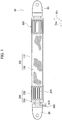
- Fig. 1 is a side view of a hydraulic actuator 10 according to the present embodiment.
- the hydraulic actuator 10 is provided with an actuator main portion 100, a sealing mechanism 200, and a sealing mechanism 300. Further, connection portions 20 are formed at both ends of the hydraulic actuator 10, respectively.
- the actuator main portion 100 is formed by a tube 110 and a sleeve 120. Fluid flows into the actuator main portion 100 via a fitting 400 and a passing hole 410.
- the actuator main portion 100 When the fluid flows into the tube 110, the actuator main portion 100 is contracted in an axial direction D AX of the actuator main portion 100 and is expanded in a radial direction D R . Further, when the fluid flows out from the tube 110, the actuator main portion 100 is expanded in the axial direction D AX of the actuator main portion 100 and is contracted in the radial direction D R . With such a shape change of the actuator main portion 100, the hydraulic actuator 10 works as an actuator.
- Examples of the fluid used for driving the hydraulic actuator 10 include gas such as air, liquid such as water and mineral oil.
- the hydraulic actuator 10 has high durability which can endure oil pressure driving in which high pressure applied to the actuator main portion 100.
- such a hydraulic actuator 10 is formed as a so-called McKibben type actuator and is preferably applied to not only an artificial muscle but also a body limb (an upper limb, a lower limb or the like) of a robot in which higher capability (contraction force) is required.
- a member which forms the body limb or the like is connected to the connection portion 20.
- the sealing mechanism 200 and the sealing mechanism 300 are formed to seal both end portions of the actuator main portion 100 in the axial direction D AX .
- the sealing mechanism 200 includes a sealing member 210 and a caulking member 230.
- the sealing member 210 is formed to seal an end portion of the actuator main portion 100 in the axial direction D AX .
- the caulking member 230 is formed to caulk the actuator main portion 100 in conjunction with the sealing member 210.
- a pressed mark 231 is formed on an outer periphery of the crimping member 230 when the caulking member 230 is crimped by a jig.
- the difference between the sealing mechanism 200 and the sealing mechanism 300 is whether the fitting 400 (and the passing hole 410) is formed.
- the fitting 400 is protruded such that the driving pressure source of the hydraulic actuator 10, specifically a hose (a pipe) connected to a compressor for gas or liquid, is mounted to the fitting 400.
- the fluid which flows in through the fitting 400 is flows into an inside of the actuator main portion 100, specifically an inside of the tube 110, after passing the passing hole 410.
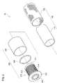
- Fig. 2 is an exploded view of a part of the hydraulic actuator 10. As shown in Fig. 2 , the hydraulic actuator 10 is provided with the actuator main portion 100 and the sealing mechanism 200.
- the actuator main portion 100 is formed by the tube 110 and the sleeve 120.
- the tube 110 is formed as a tubular body having a cylindrical shape which is expanded and contracted by pressure of fluid.
- the tube 110 is formed of an elastic material such as butyl rubber so as to allow the repeated contraction and expansion by fluid. Further, in a case in which the hydraulic actuator 10 is driven by oil pressure, NBR (nitrile rubber) having high oil resistance may be adopted.
- the sleeve 120 is formed in a cylindrical shape to cover an outer periphery of the tube 110.
- the sleeve 120 is formed as a structural body in which cords oriented in a predetermined direction are braided. The cords oriented in the predetermined direction are intersected to each other so that rhombus shapes are repeatedly formed.
- Such a shape allows the sleeve 120 to deform like a pantograph and thereby the sleeve 120 follows the deformation of the tube 110 while restricting the contraction and the expansion of the tube 110.
- the material of the cord which forms the sleeve 120 it is preferable to adopt a fiber cord formed of aromatic polyamide (aramid fiber) or polyethylene terephthalate (PET) .
- the material of the cord is not limited to such kinds of the fiber cord, and for example, a metal cord formed of a fine filament may be adopted.
- the sealing mechanism 200 is formed to seal an end portion of the actuator main portion 100 in the axial direction D AX .
- the sealing mechanism 200 is formed by a sealing member 210, a first locking ring 220, and a caulking member 230.
- the sealing member 210 includes a body portion 211 and a flange portion 212
- a metal material such as stainless steel is preferably adopted, however the material of the sealing member 210 is not limited to such metal material, and a hard plastic material may be adopted.
- the body portion 211 is formed in a tubular shape.
- a passing hole 215 through which fluid is passed is formed in the body portion 211.
- the passing hole 215 is communicated with a passing hole 410 (see Fig. 1 ).
- the body portion 211 is inserted into the tube 110.
- the flange portion 212 is continued to the body portion 211 and is arranged at a side of an end portion in the axial direction D AX of the hydraulic actuator 10 with respect to the body portion 211.
- An outer diameter of the flange portion 212 along the radial direction D R is larger than an outer diameter of the body portion 211 along the radial direction D R .
- the flange portion 212 is formed to lock the body portion 211 inserted into the tube 110 and the first locking ring 220.
- a recess and projection portion 213 is formed on the outer periphery of the body portion 211.
- the recess and projection portion 213 prevents the body portion 211 inserted into the tube 110 from slipping. It is preferable that three or more projection portions are formed in the recess and projection portion 213.
- a first small diameter portion 214 having an outer diameter smaller than the outer diameter of the body portion 211 is formed at a position closer to the flange portion 212 of the body portion 211. Further, a shape of the first small diameter portion 214 is further described with reference to Fig. 3 and following figures.
- the first locking ring 220 is formed to lock the sleeve 120. Specifically, the sleeve 120 is folded toward an outside in the radial direction D R via the first locking ring 220 (not shown in Fig. 2 , and see FIG. 3 ).
- An outer diameter of the first locking ring 220 is larger than the outer diameter of the body portion 211.
- the first locking ring 220 is formed to lock the sleeve 120 at a position of the first small diameter portion 214 of the body portion 211. That is, the first locking ring 220 locks the sleeve 120 at an outer side of the body portion 211 in the radial direction D R and at a position adjacent to the flange portion 212.
- the first locking ring 220 is formed by two divided parts. Further, the first locking ring 220 is not limited to be formed by the two divided parts, and therefore the first locking ring 220 may be formed by three or more divided parts, and a part of the divided parts may be connected in a rotatable manner.
- the material of the first locking ring 220 the metal material or the hard plastic material similar to that of the sealing member 210 can be adopted.
- the caulking member 230 is formed to caulk the actuator main portion 100 in conjunction with the sealing member 210.
- a metal material such as aluminum alloy, brass and steel can be adopted.
- the caulking member 230 is caulked by a jig for caulking the pressed mark 231 as shown in Fig. 1 is formed on the crimping member 230.
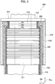
- Fig. 3 is a cross-sectional view of a part of the hydraulic actuator 10 along the axial direction D AX of the hydraulic actuator 10 including the sealing mechanism 200 according to an example 1-1.
- the sealing member 210 includes the first small diameter portion 214 having the outer diameter smaller than the outer diameter of the body portion 211.
- the first locking ring 220 is arranged at an outer side of the first small diameter portion 214 in the radial direction D R .
- An inner diameter R1 of the first locking ring 220 is smaller than an outer diameter R3 of the body portion 211.
- an outer diameter R2 of the first locking ring 220 may be also set to be smaller than the outer diameter R3 of the body portion 211.
- the body portion 211 is inserted into the tube 110 so as to be contacted with the flange portion 212.
- the sleeve 120 is folded toward the outer side in the radial direction D R via the first locking ring 220. With this, the sleeve 120 includes a first folded portion 120a folded via the first locking ring 120.
- the first folded portion 120a is adhered to the sleeve 120 located at the outer side of the tube 110 in the radial direction D R , namely adhered to an unfolded part of the sleeve 120 folded by the first locking ring 220.
- an adhesive layer 240 is formed between the sleeve 120 and the first folded portion 120a. Further, the adhesive layer 240 may be formed by using an adhesive agent suitable to a kind of the cord which forms the sleeve 120.
- the caulking member 230 is larger than the outer diameter of the body portion 211 of the sealing member 210.
- the caulking member 230 is caulked by a jig after inserted into the body portion 211.
- the caulking member 230 is formed to caulk the actuator main portion 100 in conjunction with the sealing member 210.
- the caulking member 230 is formed to caulk the tube 110 into which the body portion 211 is inserted, the sleeve 120 located at the outer side of the tube 110 in the radial direction D R , and the first folded portion 120a. That is, the caulking member 230 caulks the tube 110, the sleeve 120, and the first folded portion 120a in conjunction with the sealing member 210.
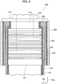
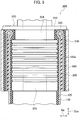
- Fig. 4 is a cross-sectional view of a part of the hydraulic actuator 10 along the axial direction D AX of the hydraulic actuator 10 including the sealing mechanism 200 according to an example 1-2.
- a configuration different from the configuration of the example 1-1 is mainly described.
- an elastic member having a sheet like shape is arranged between the first folded portion 120a of the sleeve 120 and the caulking member 230.
- a rubber sheet 250 is arranged between the first folded portion 120a and the caulking member 230.
- the rubber sheet 250 is arranged to cover an outer periphery of the first folded portion 120a having a cylindrical shape.
- a kind of the rubber sheet 250 is not especially limited, however butyl rubber can be adopted similar to the tube 110.
- the caulking member 230 is formed to caulk the actuator main portion 100 including the rubber sheet 250 in conjunction with the sealing member 210.
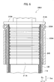
- Fig. 5 is a cross-sectional view of a part of the hydraulic actuator 10 along the axial direction D AX of the hydraulic actuator 10 including the sealing mechanism 200 according to an example 1-3.
- a rubber sheet 260 is adopted instead of the adhesive layer 240 in the example 1-1.
- the rubber sheet 260 is formed as an elastic member having a sheet like shape and is arranged between the sleeve 120 and the first folded portion 120a.
- the rubber which is a similar kind to the rubber sheet 250 can be used for the rubber sheet 260.
- Fig. 6 is a cross-sectional view of a part of the hydraulic actuator 10 along the axial direction D AX of the hydraulic actuator 10 including a sealing mechanism 200A according to an example 2-1.
- the sealing mechanism 200A is adopted instead of the sealing mechanism 200 in the examples 1.
- the difference between the sealing mechanism 200 and the sealing mechanism 200A is whether the first small diameter portion 214 formed in the sealing member 210 is formed.
- the sealing mechanism 200A is formed by a sealing member 210A, a first locking ring 220A, and a caulking member 230A.
- a body portion 211A of the sealing member 210A is inserted into the tube 110. Since the first small portion 214 is not formed in the sealing member 210A contrary to the sealing member 210, an outer diameter of the first locking ring 210A is larger than an outer diameter of the body portion 211A. Thus, the first locking ring 220A is locked by the flange portion 212A and the caulking member 230A.
- the caulking member 230A is not contacted with the flange portion 212A. That is, a part of the folded sleeve 120 corresponding to the first locking ring 220A is exposed to the outside. Further, since the outer diameter of the first locking ring 220A is larger than the outer diameter of the body portion 211A, the first locking ring 220A may not be formed by the divided parts contrary to the first locking ring 220 in the examples 1.
- the adhesive layer 240 is formed between the sleeve 120 and the first folded portion 120a.
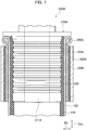
- Fig. 7 is a cross-sectional view of a part of the hydraulic actuator 10 along the axial direction D AX of the hydraulic actuator 10 including the sealing mechanism 200A according to an example 2-2.
- a configuration different from the configuration of the example 2-1 is mainly described.
- an elastic member having a sheet like shape is arranged between the first folded portion 120a of the sleeve 120 and the caulking member 230A.
- a rubber sheet 250A is arranged between the first folded portion 120a and the caulking member 230A. Similar to the rubber sheet 250 in the example 1-2, the rubber sheet 250A is arranged to cover the outer periphery of the first folded portion 120a having a cylindrical shape.
- Fig. 8 is a cross-sectional view of a part of the hydraulic actuator 10 along the axial direction D AX of the hydraulic actuator 10 including the sealing mechanism 200A according to an example 2-3.
- a rubber sheet 260 is adopted instead of the adhesive layer 240 in the example 2-1. Similar to the example 1-3, the rubber sheet 260 is formed as an elastic member having a sheet like shape and is arranged between the sleeve 120 and the first folded portion 120a.
- Fig. 9 is a cross-sectional view of a part of the hydraulic actuator 10 along the axial direction D AX of the hydraulic actuator 10 including a sealing mechanism 200B according to an example 3-1.
- a sealing mechanism 200B according to an example 3-1.
- two locking rings are adopted.
- the sealing mechanism 200B is formed by a sealing member 210B, a first locking ring 220B, a caulking member 230B, and a second locking ring 270.
- the sealing mechanism 200B includes the second locking ring 270 in addition to the first locking ring 220B.
- the second locking ring 270 locks the sleeve 120 at an outer side of the body portion 211B in the radial direction D R and at a position closer to a center of the actuator main portion 100 in the axial direction D AX than the first locking ring 220B.
- the sealing member 210B includes a second small diameter portion 216 having an outer diameter smaller than an outer diameter of the body portion 211B.
- the second locking ring 270 is arranged at an outer side of the second small diameter portion 216 in the radial direction D R . It is preferable that an inner diameter of the second locking ring 270 is smaller than the outer diameter of the body portion 211B. Further, an outer diameter of the second locking ring 270 may be also set to be smaller than the outer diameter of the body portion 211B. With this, the second locking ring 270 is locked by the second small diameter portion 216.
- the sleeve 120 includes a second folded portion 120b folded via the second locking ring 270.
- the second folded portion 120b is continued to the first folded portion 120a.
- the sleeve 120 forms the first folded portion 120a when the sleeve 120 is folded toward the center in the axial direction D AX of the actuator main portion 100 via the first locking ring 220B. Further, the sleeve 120 forms the second folded portion 120b when the first folded portion 120a is folded toward the end portion in the axial direction D AX of the actuator main portion 100.
- the caulking member 230B is formed to caulk the tube 110 into which the body portion 211B is inserted, the sleeve 120 located at the outer side of the tube 110 in the radial direction D R , the first folded portion 120a, and the second folded portion 120b in conjunction with the sealing member 210B.
- a rubber sheet 260 similar to that in the example 1-3 is arranged the sleeve 120 and the first folded portion 120a.
- an elastic member having a sheet like shape is arranged also between the first folded portion 120a and the second folded portion 120b.
- a rubber sheet 280 is arranged between the first folded portion 120a and the second folded portion 120b.
- the rubber sheet 280 is arranged to cover the outer periphery of the first folded portion 120a having a cylindrical shape.
- a rubber sheet 290 having substantially the same shape as that of the rubber sheet 250 in the example 1-3 is arranged between the second folded portion 120b and the caulking member 230B.
- the rubber sheet 290 is arranged to cover an outer periphery of the second folded portion 120b having a cylindrical shape.
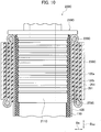
- Fig. 10 is a cross-sectional view of a part of the hydraulic actuator 10 along the axial direction D AX of the hydraulic actuator 10 including a sealing mechanism 200C according to an example 3-2.
- a configuration different from the configuration of the example 3-1 is mainly described.
- a sealing member 210C in which the first small diameter portion 214 and the second small diameter portion 216 are not formed is adopted.
- the sealing member 210C includes a body portion 211C. Since the first small diameter portion 214 and the second small diameter portion 216 are not formed in the sealing member 210C contrary to the sealing member 210B, an outer diameter of the first locking ring 220C and an outer diameter of the second locking ring 270C are larger than an outer diameter of the body portion 211C.
- the caulking member 230C is located between the first locking ring 220C and the second locking ring 270C in the axial direction D AX . That is, a part of the folded sleeve 120 corresponding to the first locking ring 220C and a part of the folded sleeve 120 corresponding to the second locking ring 270C are exposed to the outside.
- a rubber sheet 281 having substantially the same shape as that of the rubber sheet 280 in the example 3-1 is arranged between the first folded portion 120a and the second folded portion 120b. Further, a rubber sheet 291 having substantially the same shape as that of the rubber sheet 290 in the example 3-1 is arranged between the second folded portion 120b of the sleeve 120 and the caulking member 230C.
- the sealing mechanism 200 of the hydraulic actuator 10 is provided with the sealing member 210, the first locking ring 220, and the caulking member 230.
- the first locking ring 220 locks the sleeve 120.
- the sleeve 120 includes the first folded portion 120a folded via the first locking ring 220. Further, the crimping member 230 caulks the tube 110, the sleeve 120 including the first folded portion 120a in conjunction with the sealing member 210.
- the actuator main portion 100 is contracted or expanded by high pressure such as oil pressure, the actuator main portion 100, especially the sleeve 120, is hardly pulled off from the sealing mechanism 200.
- the hydraulic actuator 10 has sufficient durability in a case in which high pressure is applied such as a case in which the oil pressure driving is adopted.
- the sealing member 210 includes the first small diameter portion 214, and the inner diameter R1 of the first locking ring 220 is smaller than the outer diameter R3 of the body portion 211. With this, since the first locking ring 220 is locked by the body portion 211, the actuator main portion 100 is further hardly pulled off.
- the sleeve 120 includes the second folded portion 120b folded by the second locking ring 270 (or the second locking ring 270C).
- the actuator main portion 100 is further hardly pulled off.
- the tube 110 when the actuator main portion 100, specifically the tube 110, is expanded, the tube 110 is deformed along the second locking ring 270, and thereby the tube 110 can be prevented from deforming in a sharp angle manner. With this, the tube 110 can be prevented from being broken.
- the inner diameter of the second locking ring 270 is smaller than the outer diameter of the body portion 211B. With this, since the second locking ring 270 is locked by the body portion 211B, the actuator main portion 100 is further hardly pulled off.
- the first folded portion 120a is adhered to the sleeve 120 located at the outer side of the tube 110 in the radial direction D R by the adhesive layer 240. With this, since the sleeve 120 and the first folded portion 120a are hardly peeled from each other, the actuator main portion 100 is further hardly pulled off.
- the rubber sheet 260 is arranged between the sleeve 120 located at the outer side of the tube 110 in the radial direction D R , and the first folded portion 120a. Further, the rubber sheet 250 is arranged between the first folded portion 120a and the caulking member 230. Further, as described in the examples 3-1 and 3-2, the rubber sheet 280 (or the rubber sheet 281) is arranged between first folded portion 120a and the second folded portion 120b.
- the rubber sheet works as a cushion layer, the cord which forms the first folded portion 120a and the second folded portion 120b can be further firmly prevented from being cut.
- the sleeve 120 is formed of the organic fiber cord or the metal cord. A surface of such a cord may be coated by rubber. Further, the sleeve 120 is not limited to the structure in which the cords oriented in the predetermined direction are braided, as long as the sleeve 120 can control the contraction and the expansion of the tube 110 within a predetermined range.
- the adhesive layer 240 or the rubber sheet 260 is arranged between the sleeve 120 and the first folded portion 120a, however it may be determined to adopt either of them in accordance with durability required in the hydraulic actuator 10 and the material of the sleeve 120. That is, the adhesive layer 240 is not necessarily arranged, and therefore the first folded portion 120a may not be adhered to an unfolded part of the sleeve 120.
- a configuration of the hydraulic actuator is similar to the configuration of the hydraulic actuator 10 shown in Fig. 1 to Fig. 3 .
- a configuration of a actuator main portion 100 is different.
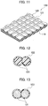
- Fig. 11 is a developed view of a part of the actuator main portion 100. As shown in Fig. 11 , the actuator main portion 100 is formed by a tube 110 and a sleeve 120.
- the tube 110 is formed as a tubular body (a pipe body) formed of an elastic material such as butyl rubber. Further, in a case in which the hydraulic actuator 10 is driven by oil pressure, NBR (nitrile rubber) having high oil resistance may be adopted.
- the sleeve 120 is arranged to cover an outer periphery of the tube 110.
- the sleeve 120 is formed by braiding cords 121 oriented to be intersected with each other.
- Fig. 12 is a cross-sectional view along a radial direction of the cord 121.
- the sleeve 120 includes a coating layer 122 which coats a surface of the cord 121.
- two cords 121 are arranged as a pair, and pairs of the cords 121 are oriented to be intersected with each other, however the number of the cords 121 forming a set may be other than two (monofilament or multifilament). In a case in which the number of the cords 121 is more than two, the cords 121 may be twisted.
- the cord 121 is formed by an organic fiber cord. Specifically, it is preferable that a fiber cord formed of aromatic polyamide (aramid fiber) or polyethylene terephthalate (PET) is adopted as the cord 121. However, an organic fiber cord other than such a fiber cord may be adopted. Further, a diameter of the fiber cord is not especially limited as long as the fiber cord does not interrupt the operation of the actuator main portion 100.
- aramid fiber aromatic polyamide
- PET polyethylene terephthalate
- a diameter of the fiber cord is not especially limited as long as the fiber cord does not interrupt the operation of the actuator main portion 100.
- pretreatment using a reactive agent such as epoxy resin may be applied to the cord 121 in order to enhance adhesiveness of the cord 121 to an aqueous mixture solution which forms the coating layer 122.
- the coating layer 122 is formed by a mixture of thermosetting resin and latex. Specifically, the coating layer 122 is formed by coating the cord 121 with an aqueous mixture solution of the thermosetting resin and the latex and then drying and heat curing the aqueous mixture solution.
- the coating layer 122 is formed by using the aqueous mixture solution in which the solid fraction (wt%) of the thermosetting resin and the latex is set in a range between 15% and 50%. More preferably, the solid fraction is set in a range between 20% and 40%.
- thermosetting resin examples include phenol resin, resorcinol resin, and urethane resin. Or alternatively, a mixture of several resins thereof may be adopted.
- latex examples include VP (styrene-butadiene-vinyl pyridine copolymer) latex, SBR (low styrene-butadiene copolymer) latex, NBR (butadiene-acrylonitrile copolymer) latex, and a mixture of several latexes thereof.
- VP styrene-butadiene-vinyl pyridine copolymer
- SBR low styrene-butadiene copolymer
- NBR butadiene-acrylonitrile copolymer
- Table 1 shows configurations of the hydraulic actuators according to comparative examples and examples, and evaluation test result thereof.
- Comparative example 1 Comparative example 2 Comparative example 3
- Example 1 Example 2
- Configuration Coating layer (resin) Resorcinol resin None Urethane resin Resorcinol resin
- Urethane resin Resorcinol-urethane resin Coating layer (latex)
- Test result Durability 100 90 95 110 110 120
- the hydraulic actuators having different coating layers according to the comparative examples 1 to 3 and the examples 1 to 3 are manufactured, and the evaluation test relating to the durability of the hydraulic actuators is executed.
- the solid fraction (wt%) of the aqueous mixture solution of the thermosetting resin and the latex used for forming the coating layer is out of the range between 15% and 50% (preferably between 20% and 40%). Further, in the comparative example 2, the latex is not used for the coating layer. On the other hand, in the examples 1 to 3, the solid fraction (wt%) of the aqueous mixture solution is in a range between 20% and 40%.
- each of the hydraulic actuators is driven by oil pressure and then the operation number (time) until damage is generated in the actuator main portion is measured.
- the values in the field of "Durability" indicate index numbers as the measurement result of the comparative example 1 is set to 100.
- the mixture of the thermosetting resin and the latex is used for the coating layer and the solid fraction thereof is in the range between 20% and 40%, and thereby the durability is enhanced drastically.
- the cord 121 is formed of the organic fiber and the coating layer 122 which coats the surface of the cord 121 is formed of the mixture of the thermosetting resin and the latex.
- the durability when the contraction and the expansion of the actuator main portion 100 are repeated may become a problem due to the damage caused by the friction between the organic fiber cord 121 and the tube 110 or the friction of the cord 121 itself.
- the cord 121 since the surface of the cord 121 is coated by the coating layer 122 formed of the mixture of the thermosetting resin and the latex, the cord 121 can be prevented from being damaged and the friction coefficient of the surface of the cord 121 can be appropriately decreased.
- the hydraulic actuator 10 has sufficient durability in a case in which high pressure is applied such as a case in which oil pressure driving is adopted.
- the coating layer 122 may be formed by using the aqueous mixture solution in which the solid fraction (wt%) of the thermosetting resin and the latex is set in a range between 15% and 50% (preferably between 20% and 40%) .
- the thermosetting resin is formed of phenol resin, resorcinol resin, urethane resin, or a mixture of several resins thereof.
- the latex is formed of VP latex, SBR latex, NBR latex, or a mixture of several latexes thereof.
- the surface of the cord 121 formed of the organic fiber can be coated easily and firmly, and the friction coefficient of the surface of the cord 121 can be decreased appropriately.
- the sealing member 210 includes the rubber sheet 250 and the rubber sheet 260 contacted with the sleeve 120.
- the sleeve 120 formed of the cord 121 which is coated by the coating layer 122 By contacting the sleeve 120 formed of the cord 121 which is coated by the coating layer 122 in such a way, an effect of preventing the sleeve 120 (the cord 121) having the friction coefficient being decreased from being pulled off from the sealing member 210 can be obtained.
- the cord 121 is coated by the coating layer 122 formed of the mixture of the thermosetting resin and the latex, the coating layer 122 and the rubber sheet 260 are adhered to each other, and therefore the excellent effect of the preventing the sleeve 120 from being pulled off can be obtained.
- a configuration of the actuator main portion 100 is similar to the configuration of the actuator main portion 100 shown in Fig. 4 .
- a configuration of the cord 121 which forms the actuator main portion 100 is different.
- Fig. 13 is a cross-sectional view along a radial direction of the cord 121.
- the sleeve 120 includes a coating layer 123 which coats a surface of the cord 121.
- the cord 121 is formed of steel, namely alloy including iron as a main component. It is preferable that a diameter of the cord 121 is equal to or less than 0.2 mm. Since the strength of the cord 121 is required, the steel of 70C or more with much carbon content is preferably adopted.
- the coating layer 123 is formed of thermoplastic resin, thermosetting resin, or a mixture of thermoplastic resin and thermosetting resin.
- thermoplastic elastomer olefin-based thermoplastic elastomer
- TPE polyester-based thermoplastic elastomer
- PP polypropylene
- PE polyethylene
- PVC polyvinyl chloride
- PA polyamide
- phenol resin epoxy resin, or urethane resin
- a mixture of several resins thereof may be adopted.
- thermoplastic resin which forms the coating layer 123 is preferably adhered to the cord 121. Further, resin modified by Maleic acid or the like may be adopted in order to enhance the adhesiveness to the cord 121.
- the caulking member 230 (see Fig. 3 ) is preferably formed of thermoplastic resin, thermosetting resin, or a mixture of the thermoplastic resin and the thermosetting resin, which is the same as the coating layer 123. That is, the caulking member 230 is preferably formed of the same resin material as that of the coating layer 123. Further, in a case in which the caulking member 230 is formed of the same thermoplastic resin as the coating layer 123, the adhesive layer 240 may not be formed.
- the adhesive layer 240 may include the same resin as the coating layer 123. Further, a sheet like member including the same resin as the coating layer 123 may be intervened between caulking member 230 and the first folded portion 120a.
- Table 2 shows configurations of the hydraulic actuators according to comparative examples and examples, and evaluation test result thereof.
- Comparative example 1 Comparative example 2
- Example 1 Example 2
- Example 3 Configuration Coating layer-resin None None Urethane PP
- Example 1 Example 2
- Example 3 Configuration Coating layer-resin None None Urethane PP
- Example 1 Example 2
- Example 3 Configuration Coating layer-resin None None Urethane PP PA Kind of cord Steel Steel Steel Steel Steel Steel Steel
- Test result Durability 100 90 115 110 110
- the hydraulic actuators according to the comparative examples 1 and 2 and the examples 1 to 3 are manufactured, and the evaluation test relating to the durability of the hydraulic actuators is executed.
- each of the hydraulic actuators according to the comparative examples 1 and 2 does not include the coating layer.
- each of the examples 1 to 3 includes the coating layer which coats the cord, and the diameter of the cord is equal to or less than 0.2 mm (0.18 mm) .
- each of the hydraulic actuators is driven by oil pressure and the operation number (time) until damage is generated in the actuator main portion is measured.
- the values in the field of "Durability" indicate index numbers as the measurement result of the comparative example 1 is set to 100.
- Each of the examples 1 to 3 includes the coating layer and the diameter of the cord is equal to or less than 0.2 mm, and thereby the durability is enhanced drastically.
- the cord 121 is formed of steel, and the coating layer 123 which coats the cord 121 is formed of the thermoplastic resin, the thermosetting resin, or the mixture of the thermoplastic resin and the thermosetting resin.
- the McKibben type hydraulic actuator like the hydraulic actuator 10
- an organic fiber cord is widely adopted.
- the cord 121 is formed of steel, the strength thereof is extremely high.
- the hydraulic actuator 10 has sufficient strength in a case in which high pressure is applied due to the oil pressure driving.
- the durability when the contraction and the expansion of the actuator main portion 100 are repeated may become a problem due to the friction between the cord 121 and the tube 110. Further, decrease of the strength due to rust of the cord 121 may also become a problem.
- the cord 121 is coated by the coating layer 123, the rust of the cord 121 can be prevented. Further, the friction coefficient of the surface of the cord 121 is decreased, and thereby the cord 121 is slipped easily. In this way, according to the hydraulic actuator 10, the durability is also enhanced.
- the hydraulic actuator 10 has sufficient durability in a case in which high pressure is applied such as a case in which oil pressure driving is adopted.
- the coating layer 123 is formed of olefin-based thermoplastic elastomer (TPE), polyester-based thermoplastic elastomer (TPE), polypropylene (PP), polyethylene (PE), polyvinyl chloride (PVC), polyamide (PA), phenol resin, epoxy resin, urethane resin, or a mixture of several resins thereof.
- TPE thermoplastic elastomer
- TPE polyester-based thermoplastic elastomer
- PP polypropylene
- PE polyethylene
- PVC polyvinyl chloride
- PA polyamide
- phenol resin epoxy resin
- epoxy resin epoxy resin
- urethane resin or a mixture of several resins thereof.
- the caulking member 230 can be formed of the thermoplastic resin, the thermosetting resin, or the mixture of the thermoplastic resin and the thermosetting resin, which is the same as the coating layer 123. In this way, by caulking the actuator main portion 100 by using resin for cushion having compatibility with the resin of the coating layer 123, the adhesiveness of the cord 121 can be enhanced.
- the caulking member 230 and the actuator main portion 100 can be integrated with each other.
- the durability of the hydraulic actuator 10 can be enhanced, and especially an effect of preventing the actuator main portion 100 from being pulled off from the sealing member 210 can be obtained.
- the diameter of the cord 121 is equal to or less than 0.2 mm. With this, sufficient flexibility of the sleeve 120 can be secured, and smooth operation of the hydraulic actuator 10 can be achieved.
- a hydraulic actuator (the hydraulic actuator 10) according to one aspect of the present invention includes an actuator main portion (the actuator main portion 100) formed by a tube (the tube 110) having a cylindrical shape which is expanded and contracted by pressure of fluid and a sleeve (the sleeve 120) formed as a structural body in which cords oriented in a predetermined direction are braided, the sleeve being formed to cover an outer periphery of the tube, and a sealing mechanism (for example, the sealing mechanism 200) which seals an end portion of the actuator main portion in an axial direction.
- a sealing mechanism for example, the sealing mechanism 200
- the sealing mechanism includes a sealing member (for example, the sealing member 210) having a body portion (the body portion 211) and a flange portion (the flange portion 212), a caulking member (the caulking member 230) which caulks the actuator main portion in conjunction with the sealing member, and a first locking ring (the first locking ring 220) which locks the sleeve.
- the tube inserted into the body portion.
- the flange portion is continued to the body portion and an outer diameter of the flange portion along a radial direction of the actuator main portion is larger than an outer diameter of the body portion.
- the first locking ring locks the sleeve at an outer side of the body portion in the radial direction.
- the sleeve includes a first folded portion (the first folded portion 120a) folded via the first locking ring.
- the caulking member caulks the tube into which the body portion is inserted, the sleeve located at the outer side of the tube in the radial direction, and the first folded portion in conjunction with the sealing member.
- the sealing member may include a first small diameter portion (the first small diameter portion 214) having an outer diameter smaller than the outer diameter of the body portion, and the first locking ring may be arranged at an outer side of the first small diameter portion in the radial direction, and at least an inner diameter of the first locking ring may be smaller than the outer diameter of the body portion.
- the sealing mechanism may include a second locking ring (for example, the second locking ring 270) which locks the sleeve at the outer side of the body portion in the radial direction and at a position closer to a center of the actuator main portion in the axial direction than the first locking ring, and the sleeve may include a second folded portion (the second folded portion 120b) folded via the second locking ring, and the second folded portion may be continued to the first folded portion, and the caulking member may caulk the tube into which the body portion is inserted, the sleeve located at the outer side of the tube in the radial direction, the first folded portion, and the second folded portion in conjunction with the sealing member.
- a second locking ring for example, the second locking ring 270
- the sleeve may include a second folded portion (the second folded portion 120b) folded via the second locking ring, and the second folded portion may be continued to the first folded portion
- the caulking member may caulk the tube into which the body
- the sealing member may include a second small diameter portion (the second small diameter portion 216) having an outer diameter smaller than the outer diameter of the body portion, and the second locking ring may be located at an outer side of the second small diameter in the radial direction, and at least an inner diameter of the second locking ring may be smaller than the outer diameter of the body portion.
- the first folded portion may be adhered to the sleeve located at an outer side of the tube in the radial direction.
- an elastic member (the rubber sheet 260) having a sheet like shape may be arranged between the sleeve located at an outer side of the tube in the radial direction and the first folded portion.
- an elastic member for example, the rubber sheet 250 having a sheet like shape may be arranged between the first folded portion and the caulking member.
- an elastic member for example, the rubber sheet 280 having a sheet like shape may be arranged between the first folded portion and the second folded portion.
- the cord may be formed of organic fiber
- the hydraulic actuator may include a coating layer which coats an surface of the cord
- the coating layer may be formed of a mixture of thermosetting resin and latex.
- the coating layer may be formed by using an aqueous mixture solution in which a solid fraction (wt%) of the thermosetting resin and the latex is in a range between 15% and 50%.
- thermosetting resin may be formed of phenol resin, resorcinol resin, urethane resin, or a mixture of several resins thereof.
- the latex may be formed of VP latex, SBR latex, NBR latex, or a mixture of several latexes thereof.
- the sealing mechanism may include a rubber sheet (for example, the rubber sheet 250) contacted with the sleeve.
- the cord may be formed of steel
- the hydraulic actuator may include a coating layer (the coating layer 123) which coats an surface of the cord
- the coating layer may be formed of thermoplastic resin, thermosetting resin, or a mixture of the thermoplastic resin and the thermosetting resin.
- the coating layer may be formed of olefin-based thermoplastic elastomer (TPE), polyester-based thermoplastic elastomer (TPE), polypropylene (PP), polyethylene (PE), polyvinyl chloride (PVC), polyamide (PA), phenol resin, epoxy resin, or urethane resin, or a mixture of several resins thereof.
- TPE olefin-based thermoplastic elastomer
- TPE polyester-based thermoplastic elastomer
- PP polypropylene
- PE polyethylene
- PVC polyvinyl chloride
- PA polyamide
- phenol resin epoxy resin
- epoxy resin epoxy resin
- urethane resin or a mixture of several resins thereof.
- the hydraulic actuator according to one aspect of the present invention has sufficient durability in a case in which high pressure is applied such as a case in which oil pressure driving is adopted.
Landscapes
- Engineering & Computer Science (AREA)
- Physics & Mathematics (AREA)
- Fluid Mechanics (AREA)
- Mechanical Engineering (AREA)
- General Engineering & Computer Science (AREA)
- Chemical & Material Sciences (AREA)
- Analytical Chemistry (AREA)
- Actuator (AREA)
Claims (15)
- Actionneur hydraulique (10) comprenant :une partie principale d'actionneur (100) formée par un tube (110) présentant une forme cylindrique qui est dilaté et contracté par la pression d'un fluide, et un manchon (120) formé comme un corps structurel dans lequel des câbles (121) orientés dans une direction prédéterminée sont tressés, le manchon (120) étant configuré afin de couvrir une périphérie extérieure du tube (110) ; etun mécanisme d'étanchéité (200, 200A, 200B, 200C) qui scelle une partie d'extrémité de la partie principale d'actionneur (100) dans une direction axiale,dans lequel :
le mécanisme d'étanchéité (200, 200A, 200B, 200C) comprend :un élément d'étanchéité (210, 210A, 210B, 210C) présentant une partie de corps (211, 211A, 211B, 211C) et une partie de bride (212, 212A) ;un élément de calfeutrage (230, 230A, 230B, 230C) qui calfeutre la partie principale de l'actionneur (100) en combinaison avec l'élément d'étanchéité (210, 210A, 210B, 210C) ; etun premier élément de verrouillage (220) qui verrouille le manchon (120) ;la partie de corps (211, 211A, 211B, 211C) est insérée dans le tube (110) ;la partie de bride (212, 212A) se poursuit jusqu'à la partie de corps (211, 211A, 211B, 211C) et un diamètre extérieur de la partie de bride (212, 212A) le long d'une direction radiale de la partie principale d'actionneur (100) est supérieur à un diamètre extérieur (R3) de la partie de corps (211, 211A, 211B, 211C) ;le premier élément de verrouillage (220) verrouille le manchon (120) sur un côté extérieur de la partie de corps (211, 211A, 211B, 211C) dans la direction radiale ;caractérisé en ce quele premier élément de verrouillage (220) est une première bague de verrouillage (220) etle manchon (120) comprend une première partie repliée (120a), repliée par le biais de la première bague de verrouillage (220) ; etl'élément de calfeutrage (230, 230A, 230B, 230C) calfeutre le tube (110) dans lequel la partie de corps (211, 211A, 211B, 211C) est insérée, le manchon (120) étant situé sur le côté extérieur du tube (110) dans la direction radiale, et la première partie repliée (120a) en combinaison avec l'élément d'étanchéité (210, 210A, 210B, 210C). - Actionneur hydraulique (10) selon la revendication 1, dans lequel :l'élément d'étanchéité (210, 210B) comprend une première partie à petit diamètre (214) présentant un diamètre externe inférieur au diamètre externe de la partie de corps (211, 211B) ;la première bague de verrouillage (220) est agencée sur un côté extérieur de la première partie de petit diamètre (214) dans la direction radiale ; etau moins un diamètre interne (R1) de la première bague de verrouillage (220) est inférieur au diamètre externe (R3) de la partie de corps (211, 211B).
- Actionneur hydraulique (10) selon la revendication 1, dans lequel :le mécanisme d'étanchéité (200B, 200C) comprend une seconde bague de verrouillage (270, 270C) qui verrouille le manchon (120) sur le côté extérieur de la partie de corps (211B, 211C) dans la direction radiale et dans une position plus proche d'un centre de la partie principale d'actionneur (100) dans la direction axiale que la première bague de verrouillage (220) ;le manchon (120) comprend une seconde partie repliée (120b) repliée par le biais de la seconde bague de verrouillage (270, 270C) ;la seconde partie repliée (120b) se poursuit jusqu'à la première partie repliée (120a) ; etl'élément de calfeutrage (230, 230A, 230B, 230C) calfeutre la partie de corps (211B, 211C) insérée dans le tube (110), le manchon (120) étant situé sur le côté extérieur du tube (110) dans la direction radiale, la première partie repliée (120a) et la seconde partie repliée (120b), en combinaison avec l'élément d'étanchéité (210B, 210C).
- Actionneur hydraulique (10) selon la revendication 3, dans lequel :l'élément d'étanchéité (210B) comprend une seconde partie de petit diamètre (216) présentant un diamètre externe inférieur au diamètre externe de la partie de corps (211B) ;la seconde bague de verrouillage (270) est située sur un côté extérieur de la seconde partie de petit diamètre (216) dans la direction radiale ; etau moins un diamètre interne de la seconde bague de verrouillage (270) est inférieur au diamètre externe de la partie de corps (211B).
- Actionneur hydraulique (10) selon la revendication 1, dans lequel la première partie repliée (120a) adhère au manchon (120) situé sur un côté extérieur du tube (110) dans la direction radiale.
- Actionneur hydraulique (10) selon la revendication 1, dans lequel un élément élastique présentant une forme de feuille est agencé entre le manchon (120) situé sur un côté extérieur du tube (110) dans la direction radiale et la première partie repliée (120a).
- Actionneur hydraulique (10) selon la revendication 1, dans lequel un élément élastique (250, 250A) présentant une forme de feuille est agencé entre la première partie repliée (120a) et l'élément de sertissage (230, 230A, 230B, 230C).
- Actionneur hydraulique (10) selon la revendication 3, dans lequel un élément élastique présentant une forme de feuille est agencé entre la première partie repliée (120a) et la seconde partie repliée (120b).
- Actionneur hydraulique (10) selon la revendication 1, dans lequel :le câble (121) est formé de fibres organiques ;l'actionneur hydraulique (10) comprend une couche de revêtement (122, 123) qui recouvre une surface du câble (121) ; etla couche de revêtement (122, 123) est formée d'un mélange de résine thermodurcissable et de latex.
- Actionneur hydraulique (10) selon la revendication 9, dans lequel la couche de revêtement (122, 123) est formée en utilisant une solution de mélange aqueux dans laquelle une fraction solide (% en poids) de la résine thermodurcissable et du latex est dans une plage comprise entre 15 % et 50 %.
- Actionneur hydraulique (10) selon la revendication 9 ou 10, dans lequel la résine thermodurcissable est formée de résine de phénol, de résine de résorcinol, de résine d'uréthane, ou d'un mélange de plusieurs résines de celles-ci.
- Actionneur hydraulique (10) selon l'une quelconque des revendications 9 à 11, dans lequel le latex est formé de latex VP, de latex SBR, de latex NBR, ou d'un mélange de plusieurs latex de ceux-ci.
- Actionneur hydraulique (10) selon l'une quelconque des revendications 9 à 12, dans lequel le mécanisme d'étanchéité comprend une feuille de caoutchouc mise en contact avec le manchon (120).
- Actionneur hydraulique (10) selon la revendication 1, dans lequel :le câble (121) est constitué d'acier ;l'actionneur hydraulique (10) comprend une couche de revêtement (122, 123) qui recouvre une surface du câble (121) ; etla couche de revêtement (122, 123) est formée de résine thermoplastique, de résine thermodurcissable, ou d'un mélange de la résine thermoplastique et de la résine thermodurcissable.
- Actionneur hydraulique (10) selon la revendication 14, dans lequel la couche de revêtement (122, 123) est formée d'un élastomère thermoplastique à base d'oléfine (TPE), d'un élastomère thermoplastique à base de polyester (TPE), de polypropylène (PP), de polyéthylène (PE), de chlorure de polyvinyle (PVC), de polyamide (PA), de résine de phénol, de résine époxy, ou de résine d'uréthane, ou d'un mélange de plusieurs résines de celles-ci.
Applications Claiming Priority (4)
| Application Number | Priority Date | Filing Date | Title |
|---|---|---|---|
| JP2015140306A JP6585943B2 (ja) | 2015-07-14 | 2015-07-14 | 流体圧アクチュエータ |
| JP2015143028A JP6585946B2 (ja) | 2015-07-17 | 2015-07-17 | 流体圧アクチュエータ |
| JP2015143155A JP6585947B2 (ja) | 2015-07-17 | 2015-07-17 | 流体圧アクチュエータ |
| PCT/JP2016/069478 WO2017010304A1 (fr) | 2015-07-14 | 2016-06-30 | Actionneur hydraulique |
Publications (3)
| Publication Number | Publication Date |
|---|---|
| EP3324054A1 EP3324054A1 (fr) | 2018-05-23 |
| EP3324054A4 EP3324054A4 (fr) | 2018-08-29 |
| EP3324054B1 true EP3324054B1 (fr) | 2019-11-20 |
Family
ID=57757844
Family Applications (1)
| Application Number | Title | Priority Date | Filing Date |
|---|---|---|---|
| EP16824284.0A Active EP3324054B1 (fr) | 2015-07-14 | 2016-06-30 | Actionneur hydraulique |
Country Status (4)
| Country | Link |
|---|---|
| US (1) | US20180202474A1 (fr) |
| EP (1) | EP3324054B1 (fr) |
| CN (1) | CN107850095A (fr) |
| WO (1) | WO2017010304A1 (fr) |
Families Citing this family (7)
| Publication number | Priority date | Publication date | Assignee | Title |
|---|---|---|---|---|
| JP6889992B2 (ja) * | 2016-09-02 | 2021-06-18 | 株式会社ブリヂストン | 流体圧アクチュエータ |
| WO2018084122A1 (fr) * | 2016-11-07 | 2018-05-11 | 株式会社ブリヂストン | Actionneur hydraulique |
| JP6928105B2 (ja) * | 2017-10-30 | 2021-09-01 | 株式会社ブリヂストン | 空気圧式アクチュエータ |
| JP2020063768A (ja) * | 2018-10-16 | 2020-04-23 | 株式会社ブリヂストン | 流体圧アクチュエータ |
| JP2020082222A (ja) | 2018-11-16 | 2020-06-04 | 株式会社ブリヂストン | 人体装着型パワーアシスト装置 |
| JP7180386B2 (ja) * | 2019-01-09 | 2022-11-30 | 横浜ゴム株式会社 | 空気式防舷材 |
| JP2020176664A (ja) | 2019-04-16 | 2020-10-29 | 株式会社ブリヂストン | 流体圧アクチュエータ及び検出ユニット |
Family Cites Families (14)
| Publication number | Priority date | Publication date | Assignee | Title |
|---|---|---|---|---|
| FR2421294A1 (fr) * | 1978-03-28 | 1979-10-26 | Europ Propulsion | Unite centrale de traitement et systeme qui y est associe |
| US4664232A (en) * | 1984-04-25 | 1987-05-12 | Bridgestone Corporation | Brake device for robot arm |
| JPS61127905A (ja) * | 1984-11-27 | 1986-06-16 | Bridgestone Corp | 弾性収縮体の端部閉鎖部材取付構造 |
| JPH0656164B2 (ja) * | 1984-12-28 | 1994-07-27 | 株式会社ブリヂストン | 弾性収縮体の端部閉鎖部材取付構造 |
| JPH0680322B2 (ja) * | 1985-09-30 | 1994-10-12 | 株式会社ブリヂストン | 弾性収縮体用閉鎖部材 |
| JP2627554B2 (ja) * | 1989-01-31 | 1997-07-09 | 日本ゼオン株式会社 | ポリエステル繊維の処理方法及びポリエステル繊維とニトリル基含有高飽和共重合体ゴムとの接着方法 |
| JP2846344B2 (ja) * | 1989-06-19 | 1999-01-13 | 株式会社ブリヂストン | 弾性伸長体を用いたアクチュエータ |
| JPH0348004A (ja) * | 1989-07-11 | 1991-03-01 | Bridgestone Corp | 複動型アクチュエータ |
| JPH08170603A (ja) * | 1994-12-16 | 1996-07-02 | Hitachi Cable Ltd | アクチュエータ |
| US6179008B1 (en) * | 1996-02-09 | 2001-01-30 | The Yokohama Rubber Co., Ltd. | Thermoplastic elastomer composition, process for the preparation there of, hose made by using the composition, and process for the production thereof |
| US6067892A (en) * | 1998-03-18 | 2000-05-30 | Erickson; Joel R. | Artificial muscle actuator assembly |
| JPWO2007058085A1 (ja) * | 2005-11-18 | 2009-04-30 | 日本シグマックス株式会社 | 流体圧式アクチュエータ |
| US7647861B2 (en) * | 2006-12-22 | 2010-01-19 | Fisher Controls International Llc | Apparatus to seal a shaft to a diaphragm for use in diaphragm actuators |
| DE102011015646A1 (de) * | 2011-03-31 | 2012-10-04 | Festo Ag & Co. Kg | Fluidbetätigter Membranantrieb |
-
2016
- 2016-06-30 WO PCT/JP2016/069478 patent/WO2017010304A1/fr not_active Ceased
- 2016-06-30 EP EP16824284.0A patent/EP3324054B1/fr active Active
- 2016-06-30 CN CN201680041400.4A patent/CN107850095A/zh active Pending
- 2016-06-30 US US15/743,473 patent/US20180202474A1/en not_active Abandoned
Also Published As
| Publication number | Publication date |
|---|---|
| EP3324054A4 (fr) | 2018-08-29 |
| CN107850095A (zh) | 2018-03-27 |
| EP3324054A1 (fr) | 2018-05-23 |
| WO2017010304A1 (fr) | 2017-01-19 |
| US20180202474A1 (en) | 2018-07-19 |
Similar Documents
| Publication | Publication Date | Title |
|---|---|---|
| EP3324054B1 (fr) | Actionneur hydraulique | |
| US20190203740A1 (en) | Hydraulic actuator | |
| CN102119294A (zh) | 护套 | |
| US7069954B2 (en) | Composite hose with a corrugated metal tube | |
| US9377137B2 (en) | Bonded high-pressure rubber hose, particularly for conveying gaseous media | |
| US11131329B2 (en) | Pneumatic actuator | |
| JP6585946B2 (ja) | 流体圧アクチュエータ | |
| JP7323551B2 (ja) | アクチュエータ | |
| JP6663798B2 (ja) | 油圧式アクチュエータ | |
| JP6929869B2 (ja) | 液圧式アクチュエータ | |
| CN118339384A (zh) | 流体压驱动器 | |
| JP6585943B2 (ja) | 流体圧アクチュエータ | |
| JP6585947B2 (ja) | 流体圧アクチュエータ | |
| JP7171994B2 (ja) | アクチュエータ用ゴム組成物、アクチュエータ用加硫ゴム及びアクチュエータ | |
| WO2020080255A1 (fr) | Actionneur hydraulique | |
| JP7171993B2 (ja) | アクチュエータ用ゴム組成物、アクチュエータ用加硫ゴム及びアクチュエータ | |
| WO2020129743A1 (fr) | Actionneur hydraulique | |
| US12421987B2 (en) | Hydraulic actuator | |
| JP2021076167A (ja) | 流体圧式アクチュエータ及び人工筋肉 | |
| JP2023090575A (ja) | 流体圧アクチュエータ及びアクチュエータ制御システム |
Legal Events
| Date | Code | Title | Description |
|---|---|---|---|
| STAA | Information on the status of an ep patent application or granted ep patent |
Free format text: STATUS: THE INTERNATIONAL PUBLICATION HAS BEEN MADE |
|
| PUAI | Public reference made under article 153(3) epc to a published international application that has entered the european phase |
Free format text: ORIGINAL CODE: 0009012 |
|
| STAA | Information on the status of an ep patent application or granted ep patent |
Free format text: STATUS: REQUEST FOR EXAMINATION WAS MADE |
|
| 17P | Request for examination filed |
Effective date: 20180122 |
|
| AK | Designated contracting states |
Kind code of ref document: A1 Designated state(s): AL AT BE BG CH CY CZ DE DK EE ES FI FR GB GR HR HU IE IS IT LI LT LU LV MC MK MT NL NO PL PT RO RS SE SI SK SM TR |
|
| AX | Request for extension of the european patent |
Extension state: BA ME |
|
| A4 | Supplementary search report drawn up and despatched |
Effective date: 20180726 |
|
| RIC1 | Information provided on ipc code assigned before grant |
Ipc: F15B 15/10 20060101AFI20180720BHEP |
|
| DAV | Request for validation of the european patent (deleted) | ||
| DAX | Request for extension of the european patent (deleted) | ||
| REG | Reference to a national code |
Ref country code: DE Ref legal event code: R079 Ref document number: 602016024836 Country of ref document: DE Free format text: PREVIOUS MAIN CLASS: F15B0015100000 Ipc: A61F0002500000 |
|
| GRAP | Despatch of communication of intention to grant a patent |
Free format text: ORIGINAL CODE: EPIDOSNIGR1 |
|
| STAA | Information on the status of an ep patent application or granted ep patent |
Free format text: STATUS: GRANT OF PATENT IS INTENDED |
|
| RIC1 | Information provided on ipc code assigned before grant |
Ipc: F15B 15/10 20060101ALI20190524BHEP Ipc: A61F 2/50 20060101AFI20190524BHEP |
|
| INTG | Intention to grant announced |
Effective date: 20190628 |
|
| GRAS | Grant fee paid |
Free format text: ORIGINAL CODE: EPIDOSNIGR3 |
|
| GRAA | (expected) grant |
Free format text: ORIGINAL CODE: 0009210 |
|
| STAA | Information on the status of an ep patent application or granted ep patent |
Free format text: STATUS: THE PATENT HAS BEEN GRANTED |
|
| AK | Designated contracting states |
Kind code of ref document: B1 Designated state(s): AL AT BE BG CH CY CZ DE DK EE ES FI FR GB GR HR HU IE IS IT LI LT LU LV MC MK MT NL NO PL PT RO RS SE SI SK SM TR |
|
| REG | Reference to a national code |
Ref country code: GB Ref legal event code: FG4D |
|
| REG | Reference to a national code |
Ref country code: CH Ref legal event code: EP |
|
| REG | Reference to a national code |
Ref country code: IE Ref legal event code: FG4D |
|
| REG | Reference to a national code |
Ref country code: DE Ref legal event code: R096 Ref document number: 602016024836 Country of ref document: DE |
|
| REG | Reference to a national code |
Ref country code: AT Ref legal event code: REF Ref document number: 1203330 Country of ref document: AT Kind code of ref document: T Effective date: 20191215 |
|
| REG | Reference to a national code |
Ref country code: NL Ref legal event code: MP Effective date: 20191120 |
|
| REG | Reference to a national code |
Ref country code: LT Ref legal event code: MG4D |
|
| PG25 | Lapsed in a contracting state [announced via postgrant information from national office to epo] |
Ref country code: NO Free format text: LAPSE BECAUSE OF FAILURE TO SUBMIT A TRANSLATION OF THE DESCRIPTION OR TO PAY THE FEE WITHIN THE PRESCRIBED TIME-LIMIT Effective date: 20200220 Ref country code: GR Free format text: LAPSE BECAUSE OF FAILURE TO SUBMIT A TRANSLATION OF THE DESCRIPTION OR TO PAY THE FEE WITHIN THE PRESCRIBED TIME-LIMIT Effective date: 20200221 Ref country code: NL Free format text: LAPSE BECAUSE OF FAILURE TO SUBMIT A TRANSLATION OF THE DESCRIPTION OR TO PAY THE FEE WITHIN THE PRESCRIBED TIME-LIMIT Effective date: 20191120 Ref country code: LT Free format text: LAPSE BECAUSE OF FAILURE TO SUBMIT A TRANSLATION OF THE DESCRIPTION OR TO PAY THE FEE WITHIN THE PRESCRIBED TIME-LIMIT Effective date: 20191120 Ref country code: SE Free format text: LAPSE BECAUSE OF FAILURE TO SUBMIT A TRANSLATION OF THE DESCRIPTION OR TO PAY THE FEE WITHIN THE PRESCRIBED TIME-LIMIT Effective date: 20191120 Ref country code: LV Free format text: LAPSE BECAUSE OF FAILURE TO SUBMIT A TRANSLATION OF THE DESCRIPTION OR TO PAY THE FEE WITHIN THE PRESCRIBED TIME-LIMIT Effective date: 20191120 Ref country code: BG Free format text: LAPSE BECAUSE OF FAILURE TO SUBMIT A TRANSLATION OF THE DESCRIPTION OR TO PAY THE FEE WITHIN THE PRESCRIBED TIME-LIMIT Effective date: 20200220 Ref country code: FI Free format text: LAPSE BECAUSE OF FAILURE TO SUBMIT A TRANSLATION OF THE DESCRIPTION OR TO PAY THE FEE WITHIN THE PRESCRIBED TIME-LIMIT Effective date: 20191120 |
|
| PG25 | Lapsed in a contracting state [announced via postgrant information from national office to epo] |
Ref country code: RS Free format text: LAPSE BECAUSE OF FAILURE TO SUBMIT A TRANSLATION OF THE DESCRIPTION OR TO PAY THE FEE WITHIN THE PRESCRIBED TIME-LIMIT Effective date: 20191120 Ref country code: HR Free format text: LAPSE BECAUSE OF FAILURE TO SUBMIT A TRANSLATION OF THE DESCRIPTION OR TO PAY THE FEE WITHIN THE PRESCRIBED TIME-LIMIT Effective date: 20191120 Ref country code: IS Free format text: LAPSE BECAUSE OF FAILURE TO SUBMIT A TRANSLATION OF THE DESCRIPTION OR TO PAY THE FEE WITHIN THE PRESCRIBED TIME-LIMIT Effective date: 20200320 |
|
| PG25 | Lapsed in a contracting state [announced via postgrant information from national office to epo] |
Ref country code: AL Free format text: LAPSE BECAUSE OF FAILURE TO SUBMIT A TRANSLATION OF THE DESCRIPTION OR TO PAY THE FEE WITHIN THE PRESCRIBED TIME-LIMIT Effective date: 20191120 |
|
| PG25 | Lapsed in a contracting state [announced via postgrant information from national office to epo] |
Ref country code: DK Free format text: LAPSE BECAUSE OF FAILURE TO SUBMIT A TRANSLATION OF THE DESCRIPTION OR TO PAY THE FEE WITHIN THE PRESCRIBED TIME-LIMIT Effective date: 20191120 Ref country code: PT Free format text: LAPSE BECAUSE OF FAILURE TO SUBMIT A TRANSLATION OF THE DESCRIPTION OR TO PAY THE FEE WITHIN THE PRESCRIBED TIME-LIMIT Effective date: 20200412 Ref country code: EE Free format text: LAPSE BECAUSE OF FAILURE TO SUBMIT A TRANSLATION OF THE DESCRIPTION OR TO PAY THE FEE WITHIN THE PRESCRIBED TIME-LIMIT Effective date: 20191120 Ref country code: ES Free format text: LAPSE BECAUSE OF FAILURE TO SUBMIT A TRANSLATION OF THE DESCRIPTION OR TO PAY THE FEE WITHIN THE PRESCRIBED TIME-LIMIT Effective date: 20191120 Ref country code: CZ Free format text: LAPSE BECAUSE OF FAILURE TO SUBMIT A TRANSLATION OF THE DESCRIPTION OR TO PAY THE FEE WITHIN THE PRESCRIBED TIME-LIMIT Effective date: 20191120 Ref country code: RO Free format text: LAPSE BECAUSE OF FAILURE TO SUBMIT A TRANSLATION OF THE DESCRIPTION OR TO PAY THE FEE WITHIN THE PRESCRIBED TIME-LIMIT Effective date: 20191120 |
|
| REG | Reference to a national code |
Ref country code: AT Ref legal event code: MK05 Ref document number: 1203330 Country of ref document: AT Kind code of ref document: T Effective date: 20191120 |
|
| REG | Reference to a national code |
Ref country code: DE Ref legal event code: R097 Ref document number: 602016024836 Country of ref document: DE |
|
| PG25 | Lapsed in a contracting state [announced via postgrant information from national office to epo] |
Ref country code: SK Free format text: LAPSE BECAUSE OF FAILURE TO SUBMIT A TRANSLATION OF THE DESCRIPTION OR TO PAY THE FEE WITHIN THE PRESCRIBED TIME-LIMIT Effective date: 20191120 Ref country code: SM Free format text: LAPSE BECAUSE OF FAILURE TO SUBMIT A TRANSLATION OF THE DESCRIPTION OR TO PAY THE FEE WITHIN THE PRESCRIBED TIME-LIMIT Effective date: 20191120 |
|
| PLBE | No opposition filed within time limit |
Free format text: ORIGINAL CODE: 0009261 |
|
| STAA | Information on the status of an ep patent application or granted ep patent |
Free format text: STATUS: NO OPPOSITION FILED WITHIN TIME LIMIT |
|
| 26N | No opposition filed |
Effective date: 20200821 |
|
| PG25 | Lapsed in a contracting state [announced via postgrant information from national office to epo] |
Ref country code: PL Free format text: LAPSE BECAUSE OF FAILURE TO SUBMIT A TRANSLATION OF THE DESCRIPTION OR TO PAY THE FEE WITHIN THE PRESCRIBED TIME-LIMIT Effective date: 20191120 Ref country code: SI Free format text: LAPSE BECAUSE OF FAILURE TO SUBMIT A TRANSLATION OF THE DESCRIPTION OR TO PAY THE FEE WITHIN THE PRESCRIBED TIME-LIMIT Effective date: 20191120 Ref country code: AT Free format text: LAPSE BECAUSE OF FAILURE TO SUBMIT A TRANSLATION OF THE DESCRIPTION OR TO PAY THE FEE WITHIN THE PRESCRIBED TIME-LIMIT Effective date: 20191120 |
|
| PG25 | Lapsed in a contracting state [announced via postgrant information from national office to epo] |
Ref country code: MC Free format text: LAPSE BECAUSE OF FAILURE TO SUBMIT A TRANSLATION OF THE DESCRIPTION OR TO PAY THE FEE WITHIN THE PRESCRIBED TIME-LIMIT Effective date: 20191120 Ref country code: IT Free format text: LAPSE BECAUSE OF FAILURE TO SUBMIT A TRANSLATION OF THE DESCRIPTION OR TO PAY THE FEE WITHIN THE PRESCRIBED TIME-LIMIT Effective date: 20191120 |
|
| REG | Reference to a national code |
Ref country code: CH Ref legal event code: PL |
|
| GBPC | Gb: european patent ceased through non-payment of renewal fee |
Effective date: 20200630 |
|
| PG25 | Lapsed in a contracting state [announced via postgrant information from national office to epo] |
Ref country code: LU Free format text: LAPSE BECAUSE OF NON-PAYMENT OF DUE FEES Effective date: 20200630 |
|
| REG | Reference to a national code |
Ref country code: BE Ref legal event code: MM Effective date: 20200630 |
|
| PG25 | Lapsed in a contracting state [announced via postgrant information from national office to epo] |
Ref country code: LI Free format text: LAPSE BECAUSE OF NON-PAYMENT OF DUE FEES Effective date: 20200630 Ref country code: CH Free format text: LAPSE BECAUSE OF NON-PAYMENT OF DUE FEES Effective date: 20200630 Ref country code: GB Free format text: LAPSE BECAUSE OF NON-PAYMENT OF DUE FEES Effective date: 20200630 Ref country code: IE Free format text: LAPSE BECAUSE OF NON-PAYMENT OF DUE FEES Effective date: 20200630 |
|
| PG25 | Lapsed in a contracting state [announced via postgrant information from national office to epo] |
Ref country code: BE Free format text: LAPSE BECAUSE OF NON-PAYMENT OF DUE FEES Effective date: 20200630 |
|
| PG25 | Lapsed in a contracting state [announced via postgrant information from national office to epo] |
Ref country code: TR Free format text: LAPSE BECAUSE OF FAILURE TO SUBMIT A TRANSLATION OF THE DESCRIPTION OR TO PAY THE FEE WITHIN THE PRESCRIBED TIME-LIMIT Effective date: 20191120 Ref country code: MT Free format text: LAPSE BECAUSE OF FAILURE TO SUBMIT A TRANSLATION OF THE DESCRIPTION OR TO PAY THE FEE WITHIN THE PRESCRIBED TIME-LIMIT Effective date: 20191120 Ref country code: CY Free format text: LAPSE BECAUSE OF FAILURE TO SUBMIT A TRANSLATION OF THE DESCRIPTION OR TO PAY THE FEE WITHIN THE PRESCRIBED TIME-LIMIT Effective date: 20191120 |
|
| PG25 | Lapsed in a contracting state [announced via postgrant information from national office to epo] |
Ref country code: MK Free format text: LAPSE BECAUSE OF FAILURE TO SUBMIT A TRANSLATION OF THE DESCRIPTION OR TO PAY THE FEE WITHIN THE PRESCRIBED TIME-LIMIT Effective date: 20191120 |
|
| P01 | Opt-out of the competence of the unified patent court (upc) registered |
Effective date: 20230531 |
|
| PGFP | Annual fee paid to national office [announced via postgrant information from national office to epo] |
Ref country code: DE Payment date: 20250618 Year of fee payment: 10 |
|
| PGFP | Annual fee paid to national office [announced via postgrant information from national office to epo] |
Ref country code: FR Payment date: 20250625 Year of fee payment: 10 |