WO2018084122A1 - Actionneur hydraulique - Google Patents
Actionneur hydraulique Download PDFInfo
- Publication number
- WO2018084122A1 WO2018084122A1 PCT/JP2017/039198 JP2017039198W WO2018084122A1 WO 2018084122 A1 WO2018084122 A1 WO 2018084122A1 JP 2017039198 W JP2017039198 W JP 2017039198W WO 2018084122 A1 WO2018084122 A1 WO 2018084122A1
- Authority
- WO
- WIPO (PCT)
- Prior art keywords
- cord
- sleeve
- actuator
- constituting
- hydraulic actuator
- Prior art date
- Legal status (The legal status is an assumption and is not a legal conclusion. Google has not performed a legal analysis and makes no representation as to the accuracy of the status listed.)
- Ceased
Links
Images




Classifications
-
- F—MECHANICAL ENGINEERING; LIGHTING; HEATING; WEAPONS; BLASTING
- F15—FLUID-PRESSURE ACTUATORS; HYDRAULICS OR PNEUMATICS IN GENERAL
- F15B—SYSTEMS ACTING BY MEANS OF FLUIDS IN GENERAL; FLUID-PRESSURE ACTUATORS, e.g. SERVOMOTORS; DETAILS OF FLUID-PRESSURE SYSTEMS, NOT OTHERWISE PROVIDED FOR
- F15B15/00—Fluid-actuated devices for displacing a member from one position to another; Gearing associated therewith
- F15B15/08—Characterised by the construction of the motor unit
- F15B15/10—Characterised by the construction of the motor unit the motor being of diaphragm type
- F15B15/103—Characterised by the construction of the motor unit the motor being of diaphragm type using inflatable bodies that contract when fluid pressure is applied, e.g. pneumatic artificial muscles or McKibben-type actuators
-
- D—TEXTILES; PAPER
- D03—WEAVING
- D03D—WOVEN FABRICS; METHODS OF WEAVING; LOOMS
- D03D1/00—Woven fabrics designed to make specified articles
- D03D1/0035—Protective fabrics
- D03D1/0043—Protective fabrics for elongated members, i.e. sleeves
-
- F—MECHANICAL ENGINEERING; LIGHTING; HEATING; WEAPONS; BLASTING
- F15—FLUID-PRESSURE ACTUATORS; HYDRAULICS OR PNEUMATICS IN GENERAL
- F15B—SYSTEMS ACTING BY MEANS OF FLUIDS IN GENERAL; FLUID-PRESSURE ACTUATORS, e.g. SERVOMOTORS; DETAILS OF FLUID-PRESSURE SYSTEMS, NOT OTHERWISE PROVIDED FOR
- F15B15/00—Fluid-actuated devices for displacing a member from one position to another; Gearing associated therewith
- F15B15/08—Characterised by the construction of the motor unit
- F15B15/10—Characterised by the construction of the motor unit the motor being of diaphragm type
-
- F—MECHANICAL ENGINEERING; LIGHTING; HEATING; WEAPONS; BLASTING
- F15—FLUID-PRESSURE ACTUATORS; HYDRAULICS OR PNEUMATICS IN GENERAL
- F15B—SYSTEMS ACTING BY MEANS OF FLUIDS IN GENERAL; FLUID-PRESSURE ACTUATORS, e.g. SERVOMOTORS; DETAILS OF FLUID-PRESSURE SYSTEMS, NOT OTHERWISE PROVIDED FOR
- F15B15/00—Fluid-actuated devices for displacing a member from one position to another; Gearing associated therewith
- F15B15/08—Characterised by the construction of the motor unit
- F15B15/14—Characterised by the construction of the motor unit of the straight-cylinder type
- F15B15/1423—Component parts; Constructional details
- F15B15/1428—Cylinders
-
- F—MECHANICAL ENGINEERING; LIGHTING; HEATING; WEAPONS; BLASTING
- F15—FLUID-PRESSURE ACTUATORS; HYDRAULICS OR PNEUMATICS IN GENERAL
- F15B—SYSTEMS ACTING BY MEANS OF FLUIDS IN GENERAL; FLUID-PRESSURE ACTUATORS, e.g. SERVOMOTORS; DETAILS OF FLUID-PRESSURE SYSTEMS, NOT OTHERWISE PROVIDED FOR
- F15B15/00—Fluid-actuated devices for displacing a member from one position to another; Gearing associated therewith
- F15B15/08—Characterised by the construction of the motor unit
- F15B15/14—Characterised by the construction of the motor unit of the straight-cylinder type
- F15B15/1423—Component parts; Constructional details
- F15B15/1438—Cylinder to end cap assemblies
-
- D—TEXTILES; PAPER
- D10—INDEXING SCHEME ASSOCIATED WITH SUBLASSES OF SECTION D, RELATING TO TEXTILES
- D10B—INDEXING SCHEME ASSOCIATED WITH SUBLASSES OF SECTION D, RELATING TO TEXTILES
- D10B2401/00—Physical properties
- D10B2401/06—Load-responsive characteristics
-
- D—TEXTILES; PAPER
- D10—INDEXING SCHEME ASSOCIATED WITH SUBLASSES OF SECTION D, RELATING TO TEXTILES
- D10B—INDEXING SCHEME ASSOCIATED WITH SUBLASSES OF SECTION D, RELATING TO TEXTILES
- D10B2505/00—Industrial
- D10B2505/02—Reinforcing materials; Prepregs
-
- F—MECHANICAL ENGINEERING; LIGHTING; HEATING; WEAPONS; BLASTING
- F15—FLUID-PRESSURE ACTUATORS; HYDRAULICS OR PNEUMATICS IN GENERAL
- F15B—SYSTEMS ACTING BY MEANS OF FLUIDS IN GENERAL; FLUID-PRESSURE ACTUATORS, e.g. SERVOMOTORS; DETAILS OF FLUID-PRESSURE SYSTEMS, NOT OTHERWISE PROVIDED FOR
- F15B2215/00—Fluid-actuated devices for displacing a member from one position to another
- F15B2215/30—Constructional details thereof
- F15B2215/305—Constructional details thereof characterised by the use of special materials
Definitions
- the present invention relates to a hydraulic actuator.
- a pneumatic tube having a rubber tube (tubular body) that expands and contracts using air as a working fluid and a sleeve (a mesh reinforcing structure) that covers the outer peripheral surface of the tube
- McKibben type a type actuator
- Both ends of the actuator main body constituted by the tube and the sleeve are caulked using a sealing member made of metal.
- the sleeve is a cylindrical structure in which high-strength fibers such as polyamide fibers or metal cords are knitted, and regulates the expansion movement of the tube within a predetermined range.
- Such a pneumatic actuator is used in various fields, and in particular, it is suitably used as an artificial muscle of a care / welfare device.
- the strength (pressure resistance) is not necessarily high, for example, the pressure resistance is about 0.5 MPa at the maximum.
- a high pressure of, for example, 50 MPa is applied, so that the conventional actuator is not sufficiently durable.
- the load on the tube increases and there is room for improvement in durability.
- an object of the present invention is to solve the above-described problems of the prior art and provide a hydraulic actuator with improved durability in an actuator that uses a liquid as a working fluid.
- the gist configuration of the present invention for solving the above-described problems is as follows.
- the hydraulic actuator according to the present invention includes a cylindrical tube that expands and contracts by a hydraulic pressure, and a sleeve that is a cylindrical structure knitted with a cord oriented in a predetermined direction and covers an outer peripheral surface of the tube.
- the hydraulic actuator according to the present invention since the sleeve is appropriately designed, the load on the tube is small and the durability is improved.
- the cord constituting the sleeve is made of at least one fiber material selected from polyamide fiber, polyester fiber, polyurethane fiber, rayon, acrylic fiber, and polyolefin fiber. In this case, the durability of the actuator is further improved.
- the sleeve includes a cord group oriented in one direction and a cord group intersecting with the cord group, wherein two cords or one cord of each cord group alternately. And the crossing positions are shifted one by one. In this case, the durability of the actuator is further improved.
- the sleeve is configured by forming the cord in a twill weave or a plain weave. Also in this case, the durability of the actuator is further improved.
- the breaking strength of the cord constituting the sleeve is 200 N / piece or more. In this case, the durability of the actuator is further improved. In the present invention, the breaking strength of the cord is measured according to JIS L1017.
- the breaking elongation of the cord constituting the sleeve is 2.0% or more. In this case, the durability of the actuator is further improved.
- the elongation at break of the cord is measured according to JIS L1017.
- the thickness of the cord constituting the sleeve is 0.3 mm to 1.5 mm. In this case, the durability of the actuator is further improved.
- the cord driving density of the sleeve is 6.8 / cm to 25.5 / cm. In this case, the durability of the actuator is further improved.
- the sleeve has a thickness t (mm), a thickness d (mm) of a cord constituting the sleeve, and the sleeve in an unloaded and non-pressurized state.
- the average angle ⁇ 1 of the cord constituting the actuator with respect to the axial direction of the actuator and the average angle ⁇ 2 of the cord constituting the sleeve with respect to the axial direction of the actuator when the actuator contracts are expressed by the following formula (1): Meet. In this case, the durability of the actuator is further improved.
- the average angle ⁇ 2 of the cords constituting the sleeve with respect to the axial direction of the actuator is a value measured at a load of 2.5 kN and a hydraulic pressure of 5 MPa.
- the thickness t (mm) of the tube, the thickness d (mm) of the cord constituting the sleeve, and the average of the cord constituting the sleeve with respect to the axial direction of the actuator in an unloaded and non-pressurized state The angle ⁇ 1 and the average angle ⁇ 2 of the cords constituting the sleeve with respect to the axial direction of the actuator when the actuator contracts are expressed by the following formula (2): It is further preferable to satisfy In this case, the durability of the actuator is further improved.
- the cord constituting the sleeve has the following formula (3): [In the formula, T 2 is the number of first twists of the cord (times / 10 cm). However, when the cord has a single twist structure, the number of upper twists T 2 (times / 10 cm) is changed to the number of lower twists T 1 (times / 10 cm). ), D is the fineness (dtex) per yarn constituting the cord, and ⁇ is the density (g / cm 3 ) of the yarn constituting the cord] The coefficient K is 0.14 to 0.50. In this case, since the sleeve is appropriately designed, the load on the tube is reduced, and the durability of the actuator is further improved.
- the cord constituting the sleeve has a ratio (T 1 ) of the number of twists T 1 (times / 10 cm) and the fineness D (dtex) per one yarn constituting the cord. / D) is preferably 0.004 to 0.03. In this case, the durability of the actuator is further improved.
- the cord constituting the sleeve has a ratio (T 1 / T 2 ) of the number of lower twists T 1 (times / 10 cm) to the number of upper twists T 2 (times / 10 cm) of 0. It is preferably 8 to 1.2. In this case, the durability of the actuator is further improved.
- the cord constituting the sleeve has a fineness D per yarn of the cord constituting the cord of 800 to 5000 dtex, and a number of twists T 1 of 3.2 to 150 times / It is preferably 10 cm, the number of twists T 2 is 2.6 to 180 times / 10 cm, and the number of twists is 2 to 4. In this case, the durability of the actuator is further improved.
- the tube has a thickness of 1.0 mm to 6.0 mm under no load and no pressure. In this case, the durability of the actuator is further improved.
- a hydraulic actuator with improved durability can be provided.
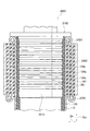
- FIG. 1 is a side view of an embodiment of a hydraulic actuator 10.
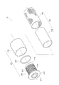
- FIG. 1 is a partially exploded perspective view of an embodiment of a hydraulic actuator 10.
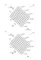
- FIG. 2 is a partial side view of two embodiments of a sleeve 120 in an unloaded and unpressurized state. It is a partial side view of two embodiment of the sleeve 120 in the state in which the average angle with respect to the axial direction of an actuator of the cord 121 which comprises the sleeve 120 is 45 degree
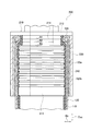
- 1 is a partial cross-sectional view taken along an axial direction D AX of a hydraulic actuator 10 including a sealing mechanism 200 according to Embodiment 1-1.
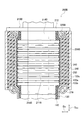
- FIG. 4 is a partial cross-sectional view along the axial direction D AX of the hydraulic actuator 10 including the sealing mechanism 200 according to Embodiment 1-2.
- FIG. 4 is a partial cross-sectional view along the axial direction D AX of the hydraulic actuator 10 including the sealing mechanism 200 according to Embodiment 1-3.
- FIG. 3 is a partial cross-sectional view along the axial direction D AX of a hydraulic actuator 10 including a sealing mechanism 200A according to Embodiment 2-1.
- FIG. 6 is a partial cross-sectional view along the axial direction D AX of the hydraulic actuator 10 including the sealing mechanism 200A according to Embodiment 2-2.
- FIG. 5 is a partial cross-sectional view along the axial direction D AX of a hydraulic actuator 10 including a sealing mechanism 200A according to Embodiment 2-3.
- 3 is a partial cross-sectional view along the axial direction D AX of a hydraulic actuator 10 including a sealing mechanism 200B according to Embodiment 3-1.
- FIG. 4 is a partial cross-sectional view along the axial direction D AX of a hydraulic actuator 10 including a sealing mechanism 200C according to Embodiment 3-2.
- FIG. 1 is a side view of a hydraulic actuator 10 according to this embodiment.
- the hydraulic actuator 10 includes an actuator body 100, a sealing mechanism 200, and a sealing mechanism 300.
- connecting portions 20 are provided at both ends of the hydraulic actuator 10.
- the actuator body 100 is composed of a tube 110 and a sleeve 120.
- the working fluid flows into the actuator body 100 through the fitting 400 and the passage hole 410.
- the actuator of the present invention is a hydraulic type, and a liquid is used as a working fluid, and examples of the liquid include oil and water.
- the actuator of the present invention may be hydraulic or hydraulic. In the case of the hydraulic type, hydraulic oil that has been conventionally used in hydraulic drive systems can be used as the hydraulic oil.
- Actuator body portion 100 by the working fluid into the tube 110 flows, contracts in the axial direction D AX of the actuator body portion 100 expands radially D R. Further, the actuator body portion 100, by which the working fluid flows out of the tube 110, and expands in the axial direction D AX of the actuator body portion 100, to radially contract D R. Due to such a shape change of the actuator main body 100, the hydraulic actuator 10 exhibits a function as an actuator.
- Such a hydraulic actuator 10 is of a so-called McKibben type, and can be applied to artificial muscles, as well as for robot limbs (upper limbs, lower limbs, etc.) that require higher ability (contraction force). Can also be suitably used.
- a member or the like constituting the limb is connected to the connecting portion 20.
- the sealing mechanism 200 and the sealing mechanism 300 seal both ends of the actuator main body 100 in the axial direction D AX .
- the sealing mechanism 200 includes a sealing member 210 and a caulking member 230.
- the sealing member 210 seals the end of the actuator main body 100 in the axial direction D AX .
- the caulking member 230 caulks the actuator main body 100 together with the sealing member 210.
- an indentation 231 that is a trace of caulking the caulking member 230 by a jig is formed.
- the difference between the sealing mechanism 200 and the sealing mechanism 300 is that the roles of the fittings 400 and 500 (and the passage holes 410 and 510) are different.
- the fitting 400 provided in the sealing mechanism 200 protrudes so that a drive pressure source of the hydraulic actuator 10, specifically, a hose (pipe) connected to a working fluid compressor can be attached.
- the working fluid that has flowed in through the fitting 400 passes through the passage hole 410 and flows into the actuator body 100, specifically, the tube 110.
- the fitting 500 provided in the sealing mechanism 300 protrudes so that it can be used as a gas vent when the working fluid is injected into the actuator.
- the gas originally present inside the actuator is discharged from the fitting 500 through the passage hole 510.
- FIG. 2 is a partially exploded perspective view of the hydraulic actuator 10.
- the hydraulic actuator 10 includes an actuator main body 100 and a sealing mechanism 200.
- the actuator main body 100 includes the tube 110 and the sleeve 120.
- the tube 110 is a cylindrical tubular body that expands and contracts by liquid pressure.
- the tube 110 is made of an elastic material such as rubber in order to repeatedly contract and expand due to the working fluid.
- the thickness of the tube 110 is preferably in the range of 1.0 mm to 6.0 mm, and more preferably in the range of 1.4 mm to 5.0 mm. If the thickness of the tube 110 is 1.0 mm or more, the strength of the tube 110 is improved, the protrusion of the tube 110 from the gap between the cords constituting the sleeve 120 can be suppressed, and the durability as an actuator is further improved. Moreover, if the thickness of the tube 110 is 6.0 mm or less, the shrinkage rate of the tube 110 will become large and sufficient operation length can be ensured.
- the tube 110 shown in FIGS. 1 and 2 has a single-layer structure, in the present invention, the tube may have a structure of two or more layers.
- the diameter (outer diameter) of the tube 110 can be appropriately selected according to the intended use.
- the sleeve 120 has a cylindrical shape and covers the outer peripheral surface of the tube 110.
- the sleeve 120 is a structure in which cords oriented in a predetermined direction are knitted, and the rhombus shape is repeated when the oriented cords intersect. Since the sleeve 120 has such a shape, the sleeve 120 is deformed into a pantograph and follows while restricting the contraction and expansion of the tube 110.
- FIG. 3 is a partial side view of two embodiments of the sleeve 120 in an unloaded and unpressurized state.
- the cord 121 constituting the sleeve 120 in the no-load and non-pressurized state that is, the initial state
- the average angle ⁇ 1 is not less than 20 degrees and less than 45 degrees.
- the average angle ⁇ 1 of the cord 121 constituting the sleeve 120 with respect to the axial direction D AX of the actuator is 20 degrees or more, so that the durability of the sleeve 120 is improved.
- the average angle ⁇ 1 of the cord 121 constituting the sleeve 120 with respect to the axial direction D AX of the actuator exceeds 45 degrees in an unloaded and non-pressurized state, the contraction at the time of operation of the actuator is small and sufficient as an actuator Will not work.
- the average angle ⁇ 1 is preferably 22 degrees or more, and more preferably 23 degrees or more. As the average angle ⁇ 1 is larger, the burden on the tube 110 is reduced, the breakage of the tube 110 that does not directly contact the cord 121 is suppressed, and the function as the actuator can be maintained for a long period of time.
- the average angle ⁇ 1 is preferably 37 degrees or less.
- the average angle ⁇ 1 of the cord 121 constituting the sleeve 120 in the initial state with respect to the axial direction D AX of the actuator is adjusted, for example, by adjusting the direction of the cord 121 when the sleeve 120 is knitted. It can be adjusted by adjusting the direction of the cord 121 at the time.
- FIG. 4 is a partial side view of two embodiments of the sleeve 120 in a state where the average angle of the cord 121 constituting the sleeve 120 with respect to the axial direction D AX of the actuator is 45 degrees.
- the average angle ⁇ 3 of the cord 121 constituting the sleeve 120 with respect to the axial direction D AX of the actuator is 45 degrees at a hydraulic pressure of 5 MPa.
- the ratio (S2 / S1) of the total area (S2) of the gap 122 of the cord 121 constituting the sleeve 120 to the area (S1) of the outer surface of the actuator body 100 is 35% or less, preferably It is at most 32%, more preferably at most 30%, even more preferably at most 25%, particularly preferably at most 20%.
- the outer surface of the actuator main body 100 Since the ratio (S2 / S1) of the total area (S2) of the gaps 122 of the cord 121 constituting the sleeve 120 to the area (S1) is 35% or less, the burden on the tube 110 is reduced and the actuator is used as an actuator. Improves durability.
- the lower limit of the ratio (S2 / S1) is not particularly limited, but the ratio (S2 / S1) is preferably 5% or more from the viewpoint of the operation length of the actuator.
- the total area (S2) of the gap 122 of the cord 121 constituting the sleeve 120 can be adjusted by selecting the method of knitting the sleeve 120, the thickness, material, driving density and the like of the cord 121 to be used.
- the total area (S2) of the gap 122 of the cord 121 constituting the sleeve 120 is 5 MPa, and the average angle ⁇ 3 of the cord 121 constituting the sleeve 120 with respect to the axial direction D AX of the actuator is It is measured by adjusting the load applied to the actuator so as to be 45 degrees. At that time, evaluation is performed in a region where the diameter of the sleeve 120 is within a range of minus 5% with respect to the maximum diameter of the sleeve 120, and the sum of the areas of the gaps 122 in the region is defined as S2. The ratio (S2 / S1) is calculated with the area of the outer surface as S1.
- the area of the gap 122 of the cord 121 constituting the sleeve 120 corresponds to the area where the cord 110 is not present and the tube 110 existing inside is exposed when the sleeve is viewed from the outside.
- the average angle theta 1 with respect to the axial direction D AX of the actuator, theta 2, theta 3 refers to the acute angle side of the angle formed by the axial direction D AX code 121 and the actuator.
- polyamide fiber such as aramid fiber (aromatic polyamide fiber), polyhexamethylene adipamide (nylon 6, 6) fiber, polycaprolactam (nylon 6) fiber, polyethylene terephthalate (PET)
- aramid fiber aromatic polyamide fiber
- nylon 6 polyhexamethylene adipamide
- nylon 6 polycaprolactam
- PET polyethylene terephthalate
- PEN polyethylene naphthalate
- the durability of the sleeve is further improved.
- a cord made of an aramid fiber from the viewpoint of the strength of the sleeve 120.
- the present invention is not limited to this type of fiber cord.
- a high-strength fiber such as PBO (polyparaphenylene benzobisoxazole) fiber or a metal cord composed of ultrafine filaments is used. Also good.
- the surface of the above-described fiber cord or metal cord may be covered with rubber, a mixture of a thermosetting resin and latex, or the like.
- the coefficient of friction on the surface of the cord can be appropriately reduced while improving the durability of the cord.
- 15 mass% or more and 50 mass% or less are preferable, and, as for the solid content rate in the mixture of a thermosetting resin and latex, 20 mass% or more and 40 mass% or less are still more preferable.
- thermosetting resins include phenol resins, resorcin resins, urethane resins, and latexes include vinylpyridine (VP) latex, styrene-butadiene rubber (SBR) latex, and acrylonitrile-butadiene rubber (NBR) latex. Etc.
- VP vinylpyridine
- SBR styrene-butadiene rubber
- NBR acrylonitrile-butadiene rubber
- the sleeve 120 includes a cord group 121A oriented in one direction and a cord group 121B intersecting with the cord group 121A. It is preferable that two cords 121B of 121B are alternately crossed each other, and the crossing positions are shifted one by one, that is, they are composed of a twill weave. In this case, the burden on the tube 110 is further reduced, and the durability as the actuator is further improved.
- the sleeve 120 includes a cord group 121A oriented in one direction and a cord group 121B intersecting with the cord group 121A.
- the cords 121 of 121A and 121B are alternately interlaced, that is, they are composed of plain weave. Also in this case, the burden on the tube 110 is further reduced, and the durability as the actuator is further improved.
- the sleeve 120 is configured by weaving the cord 121. Also in this case, the burden on the tube 110 is further reduced, and the durability as the actuator is further improved. Note that the number of cords to be arranged in the diagonal weave is not particularly limited, but in the present invention, two cords are arranged and two different cords separately arranged are driven. Is preferred.
- the breaking strength of the cord 121 constituting the sleeve 120 is preferably 200 N / line or more, more preferably in the range of 250 N / line to 1000 N / line, and in the range of 300 N / line to 1000 N / line. Is more preferable, the range of 500 N / line to 1000 N / line is even more preferable, and the range of 600 N / line to 1000 N / line is particularly preferable. In this case, the burden on the tube 110 is further reduced, and the durability of the actuator is further improved.
- the breaking elongation of the cord 121 constituting the sleeve 120 is preferably 2.0% or more, and more preferably in the range of 3.0% to 6.0%. In this case, the burden on the tube 110 is further reduced, and the durability of the actuator is further improved.
- the thickness of the cord 121 constituting the sleeve 120 is preferably 0.3 mm to 1.5 mm, more preferably 0.4 mm to 1.5 mm, and 0.5 mm to 1 mm. More preferably, it is 0.5 mm, even more preferably 0.6 mm to 1.3 mm, and particularly preferably 0.6 mm to 1.0 mm. In this case, the burden on the tube 110 is further reduced, and the durability of the actuator is further improved.
- the driving density of the cord 121 constituting the sleeve 120 is preferably 6.8 / cm to 25.5 / cm, and 10.0 / cm to 23.5 / cm. More preferably, the number is 10.0 / cm2 to 20.0 / cm. In this case, the burden on the tube 110 is further reduced, and the durability of the actuator is further improved.
- the thickness t (mm) of the tube 110, the thickness d (mm) of the cord 121 constituting the sleeve 120, and the cord 121 constituting the sleeve 120 in a no-load and no-pressurized state are expressed by the following formula (1). : It is preferable to satisfy. When Expression (1) is satisfied, the burden on the tube 110 is further reduced, and the durability as the actuator is further improved.
- the thickness t (mm) of the tube 110, the thickness d (mm) of the cord 121 constituting the sleeve 120, and the actuator of the cord 121 constituting the sleeve 120 in a no-load and no-pressurized state The average angle ⁇ 1 with respect to the axial direction D AX and the average angle ⁇ 2 of the cord 121 constituting the sleeve 120 with respect to the axial direction D AX of the sleeve 120 when the actuator contracts are expressed by the following formula (2): It is further preferable to satisfy When Expression (2) is satisfied, the burden on the tube 110 is further reduced, and the durability as the actuator is further improved.
- the cord 121 constituting the sleeve 120 is represented by the following formula (3): [In the formula, T 2 is the number of first twists of the cord (times / 10 cm). However, when the cord has a single twist structure, the number of upper twists T 2 (times / 10 cm) is changed to the number of lower twists T 1 (times / 10 cm). ), D is the fineness (dtex) per yarn constituting the cord, and ⁇ is the density (g / cm 3 ) of the yarn constituting the cord]
- the coefficient K is preferably 0.14 to 0.50, and more preferably 0.16 to 0.50.
- twist coefficient K of the cord 121 constituting the sleeve 120 is 0.14 or more, the load on the fiber is reduced, the durability of the actuator is further improved, and the twist coefficient K of the cord 121 constituting the sleeve 120 is further increased. When it is 0.50 or less, the load on the tube is reduced, and the durability of the actuator is further improved.
- the twist coefficient K of the cord 121 can be adjusted by selecting the density and fineness of the raw yarn to be used, or by adjusting the number of lower twists in the cord.
- the cord 121 composing the sleeve 120 has a ratio (T 1 / D) between the number of lower twists T 1 (times / 10 cm) and the fineness D (dtex) of one yarn constituting the cord 121. ) Is preferably 0.004 to 0.03, more preferably 0.004 to 0.02. In this case, the burden on the tube 110 is further reduced, and the durability of the actuator is further improved.
- the cord 121 constituting the sleeve 120 has a ratio (T 1 / T 2 ) between the number of lower twists T 1 (times / 10 cm) and the number of upper twists T 2 (times / 10 cm) of 0.8 to 1. .2 is preferable, and 0.9 to 1.1 is more preferable. In this case, the burden on the tube 110 is further reduced, and the durability of the actuator is further improved.
- the cord 121 constituting the sleeve 120 preferably has a fineness D per one yarn constituting the cord 121 of 800 to 5000 dtex, more preferably 800 to 4000 dtex, and more preferably 1000 to It is more preferably 4000 dtex, even more preferably 1500 to 4000 dtex, and particularly preferably 2000 to 4000 dtex. In this case, the burden on the tube 110 is further reduced, and the durability of the actuator is further improved.
- the cord 121 constituting the sleeve 120 preferably has a lower twist number T 1 of 3.2 to 150 times / 10 cm, preferably 10 to 36 times / 10 cm, and preferably 10 to 30 times / cm. More preferably, it is 10 cm. In this case, the burden on the tube 110 is further reduced, and the durability of the actuator is further improved.
- code 121 constituting the sleeve 120 is preferably the number of final twists T 2 is 2.6 to 180 times / 10 cm, preferably 10 to 36 times / 10 cm, 10 ⁇ 30 times / More preferably, it is 10 cm. In this case, the burden on the tube 110 is further reduced, and the durability of the actuator is further improved.
- the cord 121 constituting the sleeve 120 preferably has 2 to 4 twists, particularly preferably two. In this case, the burden on the tube 110 is further reduced, and the durability of the actuator is further improved.
- the cord 121 constituting the sleeve 120 has a fineness D per one yarn constituting the cord 121 of 800 to 5000 dtex, and a number of lower twists T 1 of 3.2 to 150 times / 10 cm.
- There is a top twist T 2 is 2.6 to 180 times / 10 cm, it is preferred that the twist number of 2 to 4.
- the production method of the cord 121 is not particularly limited.
- the cord 121 has a so-called double twist structure in which a plurality of yarns, preferably 2 to 4 yarns, are twisted together
- a twisted cord can be obtained by applying a lower twist to the yarn, then combining a plurality of them and applying an upper twist in the opposite direction.
- the cord 121 has a so-called single twisted structure in which one yarn is twisted, for example, the yarn can be obtained as a twisted yarn cord by arranging the yarns and twisting them in one direction.
- twist number T 1 shall refer to twist when twisting one yarn.
- T 2 in the formula (1) indicates the number of twists when twisting one raw yarn.
- the sealing mechanism 200 seals the end of the actuator main body 100 in the axial direction D AX .
- the sealing mechanism 200 includes a sealing member 210, a first locking ring 220, and a caulking member 230.
- the sealing member 210 has a body portion 211 and a flange portion 212.
- a metal such as stainless steel can be suitably used.
- the sealing member 210 is not limited to such a metal, and a hard plastic material or the like may be used.
- the body portion 211 has a circular tubular shape, and a passage hole 215 through which the working fluid passes is formed in the body portion 211.
- the passage hole 215 communicates with the passage hole 410 (see FIG. 1).
- the tube 110 is inserted through the body portion 211.
- the flange portion 212 is continuous with the body portion 211 and is located closer to the end portion in the axial direction D AX of the hydraulic actuator 10 than the body portion 211.
- the flange portion 212 has a larger outer diameter in the radial direction D R than the body portion 211.
- the flange portion 212 locks the tube 110 and the first locking ring 220 inserted through the body portion 211.
- An uneven portion 213 is formed on the outer peripheral surface of the body portion 211.
- the uneven portion 213 contributes to suppression of slippage of the tube 110 inserted through the body portion 211. It is preferable that three or more convex portions formed by the concave and convex portions 213 are formed.
- a first small-diameter portion 214 having an outer diameter smaller than that of the trunk portion 211 is formed at a position near the flange portion 212 of the trunk portion 211.
- the shape of the first small diameter portion 214 will be further described in FIG.
- the first locking ring 220 locks the sleeve 120. Specifically, the sleeve 120 is folded radially D R outward through the first locking ring 220 (not shown in FIG. 2, see FIG. 5).
- the outer diameter of the first locking ring 220 is larger than the outer diameter of the body portion 211.
- the first locking ring 220 locks the sleeve 120 at the position of the first small diameter portion 214 of the body portion 211. That is, the first locking ring 220, a radial direction D R outside of the body 211, in a position adjacent to the flange portion 212, locking the sleeve 120.
- the first locking ring 220 Since the first locking ring 220 is locked to the first small-diameter portion 214 that is smaller than the body portion 211, the first locking ring 220 has a two-divided shape in this embodiment.
- the first locking ring 220 is not limited to being divided into two parts, and may be divided into more parts, or some of the divided parts may be rotatably connected.
- the same metal or hard plastic material as the sealing member 210 can be used.
- the caulking member 230 caulks the actuator main body 100 together with the sealing member 210.
- a metal such as an aluminum alloy, brass, or iron can be used.
- an indentation 231 as shown in FIG. 1 is formed on the caulking member 230.
- FIG. 5 is a partial cross-sectional view along the axial direction D AX of the hydraulic actuator 10 including the sealing mechanism 200 according to Embodiment 1-1.
- the sealing member 210 includes the first small diameter portion 214 having an outer diameter smaller than the outer diameter of the body portion 211.
- the first locking ring 220 is disposed in the radial direction D R outside of the first small-diameter portion 214.
- the inner diameter R1 of the first locking ring 220 is smaller than the outer diameter R3 of the body portion 211.
- the outer diameter R2 of the first locking ring 220 may also be smaller than the outer diameter R3 of the body portion 211.
- the tube 110 is inserted through the body portion 211 until it comes into contact with the flange portion 212.
- the sleeve 120 is folded back radially D R outward through the first locking ring 220.
- the sleeve 120 has a first folded portion 120a that is folded back via the first locking ring 220 at the end portion in the axial direction AX .
- the sleeve 120 is disposed on the outer peripheral side of the sleeve main body 120b by being folded at the sleeve main body 120b covering the outer peripheral surface of the tube 110 and the end of the sleeve main body 120b in the axial direction D AX. And a first folded portion 120a.
- First folded portion 120a is bonded to the sleeve body portion 120b located radially D R outside of the tube 110.
- an adhesive layer 240 is formed between the sleeve main body 120b and the first folded portion 120a, and the sleeve main body 120b and the first folded portion 120a are bonded by the adhesive layer 240.
- an appropriate adhesive may be used depending on the type of cord constituting the sleeve 120.
- the adhesive layer 240 is not essential, and the first folded portion 120a may not be bonded to the sleeve main body portion 120b.
- the caulking member 230 is larger than the outer diameter of the body part 211 of the sealing member 210 and is caulked by a jig after being inserted into the body part 211.
- the caulking member 230 caulks the actuator main body 100 together with the sealing member 210.
- the caulking member 230 caulks the tube 110, the sleeve main body portion 120b, and the first folded portion 120a inserted through the body portion 211. That is, the caulking member 230 caulks the tube 110, the sleeve main body portion 120b, and the first folded portion 120a together with the sealing member 210.
- FIG. 6 is a partial cross-sectional view along the axial direction D AX of the hydraulic actuator 10 including the sealing mechanism 200 according to Embodiment 1-2.
- a sheet-like elastic member is provided between the first folded portion 120 a of the sleeve 120 and the caulking member 230.
- a rubber sheet 250 is provided between the first folded portion 120a and the caulking member 230.
- the rubber sheet 250 is provided so as to cover the outer peripheral surface of the cylindrical first folded portion 120a.
- the type of the rubber sheet 250 is not particularly limited, but the same type of rubber as the tube 110 can be used.
- the caulking member 230 caulks the actuator main body 100 together with the sealing member 210 including the rubber sheet 250.
- FIG. 7 is a partial cross-sectional view along the axial direction D AX of the hydraulic actuator 10 including the sealing mechanism 200 according to Embodiment 1-3.
- a rubber sheet 260 is used in place of the adhesive layer 240 of Embodiment 1-1.
- the rubber sheet 260 is a sheet-like elastic member, and is provided between the sleeve main body 120b and the first folded portion 120a.
- the rubber sheet 260 the same kind of rubber as the rubber sheet 250 can be used.
- FIG. 8 is a partial cross-sectional view along the axial direction D AX of the hydraulic actuator 10 including the sealing mechanism 200A according to Embodiment 2-1.
- a sealing mechanism 200A is used instead of the sealing mechanism 200 of the first embodiment.
- the difference between the sealing mechanism 200 and the sealing mechanism 200A is that the first small-diameter portion 214 like the sealing member 210 is not formed.
- the sealing mechanism 200A includes a sealing member 210A, a first locking ring 220A, and a caulking member 230A.
- the tube 110 is inserted through the body portion 211A of the sealing member 210A. Since the sealing member 210A is not formed with the first small-diameter portion 214 like the sealing member 210, the outer diameter of the first locking ring 220A is larger than the outer diameter of the body portion 211A. For this reason, the first locking ring 220A is locked by the flange portion 212A and the caulking member 230A.
- the caulking member 230A does not come into contact with the flange portion 212A. That is, the portion of the first locking ring 220A where the sleeve 120 is folded back is exposed to the outside. Furthermore, since the outer diameter of the first locking ring 220A is larger than the outer diameter of the body portion 211A, it may not be divided like the first locking ring 220 of the first embodiment.
- an adhesive layer 240 is formed between the sleeve main body 120b and the first folded portion 120a, as in the case of the embodiment 1-1.
- FIG. 9 is a partial cross-sectional view along the axial direction D AX of the hydraulic actuator 10 including the sealing mechanism 200A according to Embodiment 2-2.
- a sheet-like elastic member is provided between the first folded portion 120a of the sleeve 120 and the caulking member 230A.
- a rubber sheet 250A is provided between the first folded portion 120a and the caulking member 230A. Similar to the rubber sheet 250 of Embodiment 1-2, the rubber sheet 250A is provided so as to cover the outer peripheral surface of the cylindrical first folded portion 120a.
- FIG. 10 is a partial cross-sectional view along the axial direction D AX of the hydraulic actuator 10 including the sealing mechanism 200A according to Embodiment 2-3.
- a rubber sheet 260 is used instead of the adhesive layer 240 of the embodiment 2-1.
- the rubber sheet 260 is a sheet-like elastic member as in the embodiment 1-3, and is provided between the sleeve main body 120b and the first folded portion 120a.
- FIG. 11 is a partial cross-sectional view along the axial direction D AX of the hydraulic actuator 10 including the sealing mechanism 200B according to Embodiment 3-1.
- Embodiment 3 (3-1 and 3-2) two locking rings are used.
- the sealing mechanism 200B includes a sealing member 210B, a first locking ring 220B, a caulking member 230B, and a second locking ring 270.
- the sealing mechanism 200B includes the second locking ring 270 in addition to the first locking ring 220B.
- the second locking ring 270 a radial direction D R outside of the body 211B, at a position on the center side in the axial direction D AX of the actuator body portion 100 than the first locking ring 220B, locking the sleeve 120 To do.
- the sealing member 210B has a second small diameter portion 216B having an outer diameter smaller than the outer diameter of the body portion 211B.
- the second locking ring 270 is disposed in the radial direction D R outside of the second small diameter portion 216B.
- the inner diameter of the second locking ring 270 is preferably smaller than the outer diameter of the body portion 211B.
- the outer diameter of the second locking ring 270 may be smaller than the outer diameter of the body portion 211B.
- the sleeve 120 includes a second folded portion 120 c that is folded back via the second locking ring 270.
- the second folded portion 120c is continuous with the first folded portion 120a. That is, the second folded portion 120c is folded at the end portion of the first folded portion 120a in the axial direction D AX and arranged on the outer peripheral side of the first folded portion 120a.
- the sleeve 120 is folded back toward the center in the axial direction D AX of the actuator main body 100 via the first locking ring 220B, thereby forming the first folded portion 120a.
- the sleeve 120 forms a second folded portion 120 c by folding the first folded portion 120 a toward the end of the actuator main body 100 in the axial direction D AX .
- the tube 110 is inserted into the body portion 211B, the sleeve body 120b located radially D R outer tube 110, a first folded portion 120a, and a second folded portion 120c, or with a sealing member 210B Close.
- a rubber sheet 260 similar to that of Embodiment 1-3 is provided between the sleeve body 120b and the first folded portion 120a.
- a sheet-like elastic member is provided between the first folded portion 120a and the second folded portion 120c.
- a rubber sheet 280 is provided between the first folded portion 120a and the second folded portion 120c. The rubber sheet 280 is provided so as to cover the outer peripheral surface of the cylindrical first folded portion 120a.
- a rubber sheet 290 having substantially the same shape as the rubber sheet 250 of the embodiment 1-3 is provided between the second folded portion 120c and the caulking member 230B.
- the rubber sheet 290 is provided so as to cover the outer peripheral surface of the cylindrical second folded portion 120c.
- FIG. 12 is a partial cross-sectional view along the axial direction D AX of the hydraulic actuator 10 including the sealing mechanism 200C according to Embodiment 3-2.
- FIG. 12 is a partial cross-sectional view along the axial direction D AX of the hydraulic actuator 10 including the sealing mechanism 200C according to Embodiment 3-2.
- differences from the embodiment 3-1 will be mainly described.
- Embodiment 3-2 a sealing member 210C in which the first small diameter portion 214B and the second small diameter portion 216B are not formed is used.
- the sealing member 210C has a body portion 211C. Since the sealing member 210C is not formed with the first small diameter portion 214B and the second small diameter portion 216B as in the sealing member 210B, the inner diameter of the first locking ring 220C and the inner diameter of the second locking ring 270C are The outer diameter of the body portion 211C is larger.
- the caulking member 230C is located between the first locking ring 220C and the second locking ring 270C in the axial direction D AX . That is, the portion of the first locking ring 220C and the portion of the second locking ring 270C where the sleeve 120 is folded back are exposed to the outside.
- a rubber sheet 281 having substantially the same shape as the rubber sheet 280 of the embodiment 3-1 is provided between the first folded portion 120a and the second folded portion 120c.
- a rubber sheet 291 having substantially the same shape as the rubber sheet 290 of the embodiment 3-1 is provided between the second folded portion 120c of the sleeve 120 and the caulking member 230C.
- the obtained rubber composition was processed by an extrusion molding machine to produce a cylindrical tube having a length of 300 mm.
- Table 1 shows the outer diameter and thickness of the manufactured tube.
- a cylindrical sleeve having a mesh shape prepared by weaving 64 aramid fiber cords having the specifications shown in Table 1 was prepared. Each aramid fiber cord was produced by applying a lower twist to the aramid fiber of the original yarn and further applying an upper twist. Further, this sleeve was a mesh-like cylindrical body in which 64 aramid fiber cords were observed on the circumference in the cross section.
- the sleeve has 32 aramid fiber cords arranged at equal intervals, in parallel and in a spiral shape, and obliquely intersects with the 32 aramid fiber cords, and other sleeves arranged in an equal interval, in parallel and in a spiral shape.
- An actuator having the structure shown in FIGS. 1 and 2 was manufactured using the tube and the mesh-like sleeve.
- As the hydraulic fluid for the tube incorporated in the actuator UF46 manufactured by Cosmo Super Epoch Co., Ltd. was used.
- the angle of the cord constituting the sleeve of the manufactured actuator and the durability of the actuator were evaluated by the following methods.
- the angle formed by the cord constituting the sleeve with respect to the axial direction of the actuator was calculated as follows. (1) Take a picture of the relevant part. (2) Select the central part of the actuator (the region where the sleeve diameter is minus 5% of the maximum sleeve diameter when the actuator is contracted), which can ensure the image quality sufficient for analysis by focusing the photograph To do. (3) In this part, the angle formed by the straight line connecting the centers of the sealing mechanisms and the cord constituting the sleeve is measured. (4) Evaluate 5 points, take an average, and measure.
- the cord angle was measured in the unloaded and non-pressurized state and when the actuator was contracted with a prescribed load and fluid pressure (internal pressure).
- the former is expressed as “initial cord angle ⁇ 1. ”And the latter as“ corrosion cord angle ⁇ 2 ”.
- Table 1 shows that the hydraulic actuator according to the present invention has high durability.
Landscapes
- Engineering & Computer Science (AREA)
- Physics & Mathematics (AREA)
- Fluid Mechanics (AREA)
- Mechanical Engineering (AREA)
- General Engineering & Computer Science (AREA)
- Textile Engineering (AREA)
- Chemical & Material Sciences (AREA)
- Analytical Chemistry (AREA)
- Actuator (AREA)
Abstract
La présente invention vise à fournir un actionneur électrique de durabilité améliorée. Ceci est obtenu par un actionneur hydraulique (10) caractérisé en ce qu'il comporte un corps principal (100) d'actionneur conçu à partir d'un tube cylindrique (110) qui se dilate ou se contracte avec une pression hydraulique et un manchon tubulaire (120) dans lequel des câbles (121) orientés selon une direction prescrite sont tissés. Dans un état non chargé ou non pressurisé, l'angle moyen (Θ1) des câbles (121) par rapport à la direction axiale (DAX) de l'actionneur est supérieur ou égal à 20° et inférieur à 45°, et à une pression hydraulique de 5 MPa, dans un état dans lequel l'angle moyen (Θ3) des câbles (121) par rapport à la direction axiale (DAX) de l'actionneur est de 45°, le rapport (S2/S1) de la surface totale (S2) des intervalles (122) entre les câbles (121) à superficie (S1) de la surface externe du corps principal (100) d'actionneur est inférieur ou égal à 35 %.<sb />
Priority Applications (4)
| Application Number | Priority Date | Filing Date | Title |
|---|---|---|---|
| US16/347,728 US10774855B2 (en) | 2016-11-07 | 2017-10-30 | Hydraulic actuator |
| JP2018549000A JP6929869B2 (ja) | 2016-11-07 | 2017-10-30 | 液圧式アクチュエータ |
| EP17867814.0A EP3536982A4 (fr) | 2016-11-07 | 2017-10-30 | Actionneur hydraulique |
| CN201780068447.4A CN109906320B (zh) | 2016-11-07 | 2017-10-30 | 液压致动器 |
Applications Claiming Priority (4)
| Application Number | Priority Date | Filing Date | Title |
|---|---|---|---|
| JP2016-217526 | 2016-11-07 | ||
| JP2016217526 | 2016-11-07 | ||
| JP2017-008960 | 2017-01-20 | ||
| JP2017008960 | 2017-01-20 |
Publications (1)
| Publication Number | Publication Date |
|---|---|
| WO2018084122A1 true WO2018084122A1 (fr) | 2018-05-11 |
Family
ID=62075576
Family Applications (1)
| Application Number | Title | Priority Date | Filing Date |
|---|---|---|---|
| PCT/JP2017/039198 Ceased WO2018084122A1 (fr) | 2016-11-07 | 2017-10-30 | Actionneur hydraulique |
Country Status (5)
| Country | Link |
|---|---|
| US (1) | US10774855B2 (fr) |
| EP (1) | EP3536982A4 (fr) |
| JP (1) | JP6929869B2 (fr) |
| CN (1) | CN109906320B (fr) |
| WO (1) | WO2018084122A1 (fr) |
Cited By (2)
| Publication number | Priority date | Publication date | Assignee | Title |
|---|---|---|---|---|
| WO2020080545A1 (fr) * | 2018-10-19 | 2020-04-23 | 株式会社ブリヂストン | Actionneur |
| JP2021092228A (ja) * | 2019-12-06 | 2021-06-17 | 株式会社ブリヂストン | 流体圧式アクチュエータ及び人工筋肉 |
Families Citing this family (1)
| Publication number | Priority date | Publication date | Assignee | Title |
|---|---|---|---|---|
| JP6928105B2 (ja) * | 2017-10-30 | 2021-09-01 | 株式会社ブリヂストン | 空気圧式アクチュエータ |
Citations (4)
| Publication number | Priority date | Publication date | Assignee | Title |
|---|---|---|---|---|
| JPS61236905A (ja) | 1985-04-12 | 1986-10-22 | Bridgestone Corp | ニユ−マチツク・アクチユエ−タ |
| US4721030A (en) * | 1985-07-16 | 1988-01-26 | Paynter Henry M | Hyperboloid of revolution fluid-driven tension actuators and method of making |
| JP2016156116A (ja) * | 2015-02-25 | 2016-09-01 | 国立大学法人東京工業大学 | 能動織布 |
| JP2017046754A (ja) * | 2015-08-31 | 2017-03-09 | ダイヤ工業株式会社 | アクチュエータ及び身体支援装置 |
Family Cites Families (36)
| Publication number | Priority date | Publication date | Assignee | Title |
|---|---|---|---|---|
| US3645173A (en) | 1969-10-20 | 1972-02-29 | Trish Energetics Inc | Fluid actuator |
| JPS5240378B2 (fr) * | 1971-08-03 | 1977-10-12 | ||
| EP0123558B1 (fr) * | 1983-04-25 | 1990-11-14 | Bridgestone Corporation | Actionneur pneumatique pour manipulateur |
| JPS60227003A (ja) * | 1984-04-25 | 1985-11-12 | Bridgestone Corp | 高忠実性の内圧応動弾性収縮筒 |
| US4860639A (en) * | 1984-12-11 | 1989-08-29 | Bridgestone Corporation | Flexible tubular wall actuator with end-mounted strain gauge |
| JPH0656164B2 (ja) * | 1984-12-28 | 1994-07-27 | 株式会社ブリヂストン | 弾性収縮体の端部閉鎖部材取付構造 |
| JPS61279551A (ja) * | 1985-06-05 | 1986-12-10 | 株式会社ブリヂストン | 弾性収縮体 |
| JPS6262005A (ja) * | 1985-09-11 | 1987-03-18 | Bridgestone Corp | 弾性収縮体 |
| JPH0449429Y2 (fr) | 1988-09-06 | 1992-11-20 | ||
| JP2846346B2 (ja) | 1989-06-23 | 1999-01-13 | 株式会社ブリヂストン | 湾曲可能なアクチュエータ |
| JPH0348004A (ja) * | 1989-07-11 | 1991-03-01 | Bridgestone Corp | 複動型アクチュエータ |
| US5080020A (en) * | 1989-07-14 | 1992-01-14 | Nihon Kohden Corporation | Traveling device having elastic contractible body moving along elongated member |
| JPH04145206A (ja) * | 1990-10-04 | 1992-05-19 | Bridgestone Corp | 中空型弾性伸縮体 |
| JPH05164112A (ja) | 1991-12-13 | 1993-06-29 | Toshiba Corp | アクチュエータ及びその製造方法 |
| JP3007467B2 (ja) | 1992-02-20 | 2000-02-07 | 株式会社ブリヂストン | 二輪車用空気入りラジアルタイヤ |
| JPH08170603A (ja) * | 1994-12-16 | 1996-07-02 | Hitachi Cable Ltd | アクチュエータ |
| CN2297379Y (zh) | 1996-11-25 | 1998-11-18 | 易志乾 | 内胆式高强度气囊 |
| JP2000018444A (ja) * | 1998-07-03 | 2000-01-18 | Bridgestone Corp | 媒体輸送用ホース |
| US20020108491A1 (en) * | 2001-02-13 | 2002-08-15 | Stahn Kevin S. | Tension actuator having constraining sleeve immersed in a single layer of elastomeric material |
| WO2004085856A1 (fr) * | 2003-03-25 | 2004-10-07 | Hitachi Medical Corporation | Actionneur a pression hydraulique et dispositif d'exercice manuel continu comprenant cet actionneur |
| CN101113745A (zh) | 2003-03-25 | 2008-01-30 | 株式会社日立医药 | 流体压式致动装置 |
| US7438961B2 (en) | 2006-01-10 | 2008-10-21 | Amerityre | Plies sleeve for use in forming an elastomeric tire |
| JP3132568U (ja) * | 2007-04-02 | 2007-06-14 | 東京工研株式会社 | ホース |
| WO2008140032A1 (fr) * | 2007-05-11 | 2008-11-20 | Chuo University | Actionneur du type à déversement de fluide |
| JP5280659B2 (ja) * | 2007-09-11 | 2013-09-04 | 新明和工業株式会社 | 弾性収縮体を備えたアクチュエータ、そのアクチュエータを備えた把持機構、および、その把持機構を備えたロボットハンド。 |
| JP5393212B2 (ja) | 2009-03-19 | 2014-01-22 | オリンパス株式会社 | アクチュエータ |
| JP2012207329A (ja) * | 2011-03-29 | 2012-10-25 | Unitika Ltd | ポリエステル繊維およびそれを用いたネット |
| JP5829054B2 (ja) * | 2011-06-03 | 2015-12-09 | クボタシーアイ株式会社 | 管路補修部材およびそれを用いた管路ならびに管路補修部材の製造方法 |
| JP5966634B2 (ja) * | 2012-06-04 | 2016-08-10 | 横浜ゴム株式会社 | マリンホース |
| JP5790637B2 (ja) * | 2012-12-20 | 2015-10-07 | 横浜ゴム株式会社 | 空気式防舷材 |
| JP6226359B2 (ja) | 2013-05-16 | 2017-11-08 | 国立大学法人 岡山大学 | 流体圧式アクチュエータおよび湾曲駆動装置 |
| JP6226360B2 (ja) * | 2013-05-16 | 2017-11-08 | 国立大学法人 岡山大学 | 流体圧式アクチュエータおよび湾曲駆動装置 |
| US9835184B2 (en) * | 2013-08-10 | 2017-12-05 | The Regents Of The University Of Michigan | Fiber-reinforced actuator |
| WO2015146624A1 (fr) * | 2014-03-28 | 2015-10-01 | 東洋紡株式会社 | Multifilament et tresse |
| WO2017010304A1 (fr) * | 2015-07-14 | 2017-01-19 | 株式会社ブリヂストン | Actionneur hydraulique |
| JP6663798B2 (ja) | 2016-05-31 | 2020-03-13 | 株式会社ブリヂストン | 油圧式アクチュエータ |
-
2017
- 2017-10-30 WO PCT/JP2017/039198 patent/WO2018084122A1/fr not_active Ceased
- 2017-10-30 EP EP17867814.0A patent/EP3536982A4/fr not_active Withdrawn
- 2017-10-30 JP JP2018549000A patent/JP6929869B2/ja active Active
- 2017-10-30 US US16/347,728 patent/US10774855B2/en active Active
- 2017-10-30 CN CN201780068447.4A patent/CN109906320B/zh not_active Expired - Fee Related
Patent Citations (4)
| Publication number | Priority date | Publication date | Assignee | Title |
|---|---|---|---|---|
| JPS61236905A (ja) | 1985-04-12 | 1986-10-22 | Bridgestone Corp | ニユ−マチツク・アクチユエ−タ |
| US4721030A (en) * | 1985-07-16 | 1988-01-26 | Paynter Henry M | Hyperboloid of revolution fluid-driven tension actuators and method of making |
| JP2016156116A (ja) * | 2015-02-25 | 2016-09-01 | 国立大学法人東京工業大学 | 能動織布 |
| JP2017046754A (ja) * | 2015-08-31 | 2017-03-09 | ダイヤ工業株式会社 | アクチュエータ及び身体支援装置 |
Cited By (8)
| Publication number | Priority date | Publication date | Assignee | Title |
|---|---|---|---|---|
| WO2020080545A1 (fr) * | 2018-10-19 | 2020-04-23 | 株式会社ブリヂストン | Actionneur |
| CN112912632A (zh) * | 2018-10-19 | 2021-06-04 | 株式会社普利司通 | 致动器 |
| JPWO2020080545A1 (ja) * | 2018-10-19 | 2021-09-16 | 株式会社ブリヂストン | アクチュエータ |
| EP3869046A4 (fr) * | 2018-10-19 | 2022-06-22 | Bridgestone Corporation | Actionneur |
| JP7323551B2 (ja) | 2018-10-19 | 2023-08-08 | 株式会社ブリヂストン | アクチュエータ |
| US11821114B2 (en) | 2018-10-19 | 2023-11-21 | Bridgestone Corporation | Actuator |
| JP2021092228A (ja) * | 2019-12-06 | 2021-06-17 | 株式会社ブリヂストン | 流体圧式アクチュエータ及び人工筋肉 |
| JP7394608B2 (ja) | 2019-12-06 | 2023-12-08 | 株式会社ブリヂストン | 流体圧式アクチュエータ及び人工筋肉 |
Also Published As
| Publication number | Publication date |
|---|---|
| CN109906320B (zh) | 2020-10-16 |
| CN109906320A (zh) | 2019-06-18 |
| JP6929869B2 (ja) | 2021-09-01 |
| EP3536982A4 (fr) | 2020-06-17 |
| EP3536982A1 (fr) | 2019-09-11 |
| US20190285095A1 (en) | 2019-09-19 |
| US10774855B2 (en) | 2020-09-15 |
| JPWO2018084122A1 (ja) | 2019-09-19 |
Similar Documents
| Publication | Publication Date | Title |
|---|---|---|
| US11131329B2 (en) | Pneumatic actuator | |
| JP6929869B2 (ja) | 液圧式アクチュエータ | |
| US7614428B2 (en) | Power steering hose design for performance in high pressure and low to high volumeric expansion environments | |
| US11821114B2 (en) | Actuator | |
| CN107850095A (zh) | 流体压致动器 | |
| US20190316608A1 (en) | Hydraulic actuator | |
| US9377137B2 (en) | Bonded high-pressure rubber hose, particularly for conveying gaseous media | |
| JP7394608B2 (ja) | 流体圧式アクチュエータ及び人工筋肉 | |
| JP6663798B2 (ja) | 油圧式アクチュエータ | |
| JP6865635B2 (ja) | 液圧式アクチュエータ | |
| JP6908466B2 (ja) | 液圧式アクチュエータ | |
| JP7171994B2 (ja) | アクチュエータ用ゴム組成物、アクチュエータ用加硫ゴム及びアクチュエータ | |
| JP7171993B2 (ja) | アクチュエータ用ゴム組成物、アクチュエータ用加硫ゴム及びアクチュエータ | |
| JP4760114B2 (ja) | ホース | |
| JP2021076167A (ja) | 流体圧式アクチュエータ及び人工筋肉 | |
| KR102241023B1 (ko) | 구슬밴드를 포함하는 다층 복합 고무 호스 및 이의 제조 방법 |
Legal Events
| Date | Code | Title | Description |
|---|---|---|---|
| 121 | Ep: the epo has been informed by wipo that ep was designated in this application |
Ref document number: 17867814 Country of ref document: EP Kind code of ref document: A1 |
|
| ENP | Entry into the national phase |
Ref document number: 2018549000 Country of ref document: JP Kind code of ref document: A |
|
| NENP | Non-entry into the national phase |
Ref country code: DE |
|
| ENP | Entry into the national phase |
Ref document number: 2017867814 Country of ref document: EP Effective date: 20190607 |