EP3326826A1 - Imprimante thermique - Google Patents
Imprimante thermique Download PDFInfo
- Publication number
- EP3326826A1 EP3326826A1 EP18152145.1A EP18152145A EP3326826A1 EP 3326826 A1 EP3326826 A1 EP 3326826A1 EP 18152145 A EP18152145 A EP 18152145A EP 3326826 A1 EP3326826 A1 EP 3326826A1
- Authority
- EP
- European Patent Office
- Prior art keywords
- energy
- gradation
- image
- level
- levels
- Prior art date
- Legal status (The legal status is an assumption and is not a legal conclusion. Google has not performed a legal analysis and makes no representation as to the accuracy of the status listed.)
- Granted
Links
Images







Classifications
-
- B—PERFORMING OPERATIONS; TRANSPORTING
- B41—PRINTING; LINING MACHINES; TYPEWRITERS; STAMPS
- B41J—TYPEWRITERS; SELECTIVE PRINTING MECHANISMS, i.e. MECHANISMS PRINTING OTHERWISE THAN FROM A FORME; CORRECTION OF TYPOGRAPHICAL ERRORS
- B41J2/00—Typewriters or selective printing mechanisms characterised by the printing or marking process for which they are designed
- B41J2/315—Typewriters or selective printing mechanisms characterised by the printing or marking process for which they are designed characterised by selective application of heat to a heat sensitive printing or impression-transfer material
- B41J2/32—Typewriters or selective printing mechanisms characterised by the printing or marking process for which they are designed characterised by selective application of heat to a heat sensitive printing or impression-transfer material using thermal heads
- B41J2/35—Typewriters or selective printing mechanisms characterised by the printing or marking process for which they are designed characterised by selective application of heat to a heat sensitive printing or impression-transfer material using thermal heads providing current or voltage to the thermal head
- B41J2/355—Control circuits for heating-element selection
- B41J2/3555—Historical control
-
- B—PERFORMING OPERATIONS; TRANSPORTING
- B41—PRINTING; LINING MACHINES; TYPEWRITERS; STAMPS
- B41J—TYPEWRITERS; SELECTIVE PRINTING MECHANISMS, i.e. MECHANISMS PRINTING OTHERWISE THAN FROM A FORME; CORRECTION OF TYPOGRAPHICAL ERRORS
- B41J2/00—Typewriters or selective printing mechanisms characterised by the printing or marking process for which they are designed
- B41J2/315—Typewriters or selective printing mechanisms characterised by the printing or marking process for which they are designed characterised by selective application of heat to a heat sensitive printing or impression-transfer material
- B41J2/32—Typewriters or selective printing mechanisms characterised by the printing or marking process for which they are designed characterised by selective application of heat to a heat sensitive printing or impression-transfer material using thermal heads
- B41J2/35—Typewriters or selective printing mechanisms characterised by the printing or marking process for which they are designed characterised by selective application of heat to a heat sensitive printing or impression-transfer material using thermal heads providing current or voltage to the thermal head
- B41J2/355—Control circuits for heating-element selection
- B41J2/36—Print density control
-
- B—PERFORMING OPERATIONS; TRANSPORTING
- B41—PRINTING; LINING MACHINES; TYPEWRITERS; STAMPS
- B41J—TYPEWRITERS; SELECTIVE PRINTING MECHANISMS, i.e. MECHANISMS PRINTING OTHERWISE THAN FROM A FORME; CORRECTION OF TYPOGRAPHICAL ERRORS
- B41J2/00—Typewriters or selective printing mechanisms characterised by the printing or marking process for which they are designed
- B41J2/315—Typewriters or selective printing mechanisms characterised by the printing or marking process for which they are designed characterised by selective application of heat to a heat sensitive printing or impression-transfer material
- B41J2/32—Typewriters or selective printing mechanisms characterised by the printing or marking process for which they are designed characterised by selective application of heat to a heat sensitive printing or impression-transfer material using thermal heads
- B41J2/35—Typewriters or selective printing mechanisms characterised by the printing or marking process for which they are designed characterised by selective application of heat to a heat sensitive printing or impression-transfer material using thermal heads providing current or voltage to the thermal head
- B41J2/355—Control circuits for heating-element selection
- B41J2/36—Print density control
- B41J2/365—Print density control by compensation for variation in temperature
Definitions
- An aspect of this disclosure relates to a thermal printer.
- a known thermal printer includes multiple heating elements that generate heat corresponding to the amounts of energy applied, and forms a multi-gradation image on a recording medium.
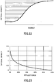
- gradation levels are determined based on a relationship, which is illustrated in FIG. 22 , between the optical density of a printed image and the energy applied to the heating elements such that differences in optical density between the gradation levels become substantially the same, and the amounts of energy applied to the heating elements are set for the respective gradation levels.
- Japanese Laid-Open Patent Publication No. 04-220358 discloses a thermal printer where the amounts of energy applied to heating elements are determined based on linear approximation of the relationship between the optical density of a printed image and energy applied to the heating elements in a medium density range, in order to reduce the processing load.
- optical density ⁇ log reflectance
- the reflectance changes sharply in a low optical density range and changes gradually in a high optical density range. Therefore, even when the amounts of energy applied to heating elements so as the optical density changes at a constant interval as illustrated in FIG. 22 , changes in reflectance in a high density range may become small and the gradation reproducibility may become low.
- FIG. 24A illustrates an exemplary printed image printed by applying energy to heating elements at levels that are determined based on the relationship between the optical density and the energy illustrated in FIG. 22 such that changes in optical densities between gradation levels are substantially the same.
- FIG. 24B illustrates an exemplary printed image printed by applying energy to heating elements at levels that are determined based on linear approximation of the relationship between the optical density and the applied energy.
- a thermal printer including heating elements that generate heat according to amounts of applied energy, an energy applier that applies energy to the heating elements, a memory that stores a gradation table where energy levels to be applied to the heating elements are set for gradation levels based on a relationship between dot area ratios of an image and the amounts of energy applied to the heating elements, and a controller that transfers control data multiple times to the energy applier based on the gradation table to control the amounts of energy to be applied by the energy applier to the heating elements, each of the control data corresponding to different amounts of energy.
- FIG. 1 is a drawing illustrating an exemplary configuration of a thermal printer 100 according to an embodiment.
- the thermal printer 100 includes a micro control unit (MCU) 10, a random access memory (RAM) 11, a thermistor 12, a shift register 14, a latch register 16, a power supply 17, a voltage dividing circuit 18, integrated circuits (IC) 1-640, and heating elements R1-R640.
- the heating elements may be collectively referred to as "heating elements R”.
- the heating elements R are provided in a thermal head and arranged in a line along the main scanning direction.
- the respective heating elements R generate heat corresponding to the level of applied energy to heat a recording medium such as thermal paper and form an image on the recording medium.
- the thermal printer 100 can print 640 dots per print line on a recording medium.
- the heating elements R are grouped into printing blocks corresponding to print areas, and the printing blocks are separately controlled.
- the heating elements R1-R640 are grouped into four printing blocks each including 160 heating elements: heating elements R1-R160, heating elements R161-R320, heating elements R321-R480, and heating elements R481-R640.
- the number of heating elements and the number of printing blocks are not limited to this example.
- the MCU 10 is an example of a controller.
- the MCU 10 sets the amounts of energy to be applied to the heating elements R based on the gradation levels of an image to be printed, and sends various signals to the shift register 14, the latch register 16, and the ICs.
- the shift register 14, the latch register 16, the ICs, and the power supply 17 forms an energy applier for applying energy to the heating elements R.
- the MCU 10 generates a DI signal for controlling the heating elements R based on image data input to the thermal printer 100 and a gradation table stored in the RAM 11, and sends the generated DI signal to the shift register 14 via a clock synchronous serial communication. After transmitting the DI signal for one print line to the shift register 14, the MCU 10 sends a /LAT signal to the latch register 16 to cause the latch register 16 to latch data in the shift register 14.
- the RAM 11 is an example of a memory, and stores a gradation table that contains energy values corresponding to gradation levels.
- the shift register 14 stores 640-bit data, and includes data areas each of which stores one bit of data. Each bit of the shift register 14 corresponds to one of the heating elements R. For example, bit 0 corresponds to the heating element R1, and bit 639 corresponds to the heating element R640.
- the data stored in the shift register 14 is used to control the heating elements. When a bit is 1, the corresponding heating element R is turned on; and when a bit is 0, the corresponding heating element R is turned off.
- the latch register 16 includes data areas corresponding to the heating elements R.
- the latch register 16 latches signals sent from the shift register 14 when receiving the /LAT signal from the MCU 10.
- the signals latched by the latch register 16 are input to the ICs.
- Each one of the ICs 1-640 is provided for, and is connected to the corresponding heating elements R1-R640.
- the ICs are turned on and off by STB signals.
- an IC receives a signal "1" from the latch register 16 and receives an STB signal "ON” from the MCU 10, the IC supplies power to the corresponding heating element. Power is supplied to each heating element R while the STB signal is ON. That is, the power-supply period of each heating element R is controlled by the STB signal. The amount of energy supplied to each heating element R increases as the power-supply period increases.
- the MCU 10 sends an STB signal for each of the printing blocks.
- the MCU 10 sends an STB1 signal to the ICs 1-160, an STB2 signal to the ICs 161-320, an STB3 signal to the ICs 321-480, and an STB4 signal to the ICs 481-640, to separately control the printing blocks.
- the power supply 17 is connected to, and applies a voltage V to the heating elements R.
- the MCU 10 obtains amount of the voltage V applied from the power supply 17 to the heating elements R based on a voltage Vin obtained by the voltage dividing circuit 18 by dividing the voltage V.
- the thermistor 12 is an example of a temperature detector, and measures a temperature of the thermal head where the heating elements R are provided, and sends measured temperature to the MCU 10.
- a gradation table used to control the energy to be applied to the heating elements R is described.
- a grayscale between white and black is divided based on reflectances. As illustrated in FIG. 2 , the reflectance is proportional to the dot area ratio.
- the relationship between the dot area ratio and the optical density is represented by a Murray-Davies equation.
- D 0 indicates the density of paper
- D s indicates a saturation density
- D t indicates a printed-area density
- dot area ratio A is represented by formula (1) below.
- a % 100 ⁇ 1 ⁇ 10 ⁇ D t ⁇ D 0 1 ⁇ 10 ⁇ D s ⁇ D 0
- gradation levels are determined based on a relationship between the energy applied to the heating element and the dot area ratio of an image as indicated by FIG. 3 such that differences in the dot area ratio between any two adjacent gradation levels become substantially the same, and energy values corresponding to the determined gradation levels are set.
- FIG. 3 illustrates an example of 16 gradation levels obtained by dividing a range between a dot area ratio of 0% (white) and 100% (black) into 15 equal parts, and energy values corresponding to the gradation levels.
- FIG. 4 is a graph illustrating an exemplary relationship between 16 gradation levels and energy values derived from FIG. 3 .
- an energy value of 100% corresponds to the energy value at the dot area ratio of 100% (the maximum gradation level) in FIG. 3 .
- energy values representing the amounts of energy to be applied to the heating elements R for respective gradation levels are determined based on the relationship between the dot area ratio and the applied energy, and the determined energy values are stored in the RAM 11 as a gradation table.
- Table 1 is an example of the gradation table.
- Storing energy values for respective gradation levels in advance as a gradation table eliminates the need to calculate an energy value corresponding to a gradation level of an image to be printed based on a relationship between gradation levels and energy values.
- Table 1 includes gradation levels 0-15 used to print a 16-gradation-level image. However, depending on the number of gradation levels of image data to be printed, a different gradation table with 4 gradation levels or 32 gradation levels may be stored in the RAM 11. Also, multiple gradation tables of different gradation levels may be stored. Table 2 is an example of a gradation table with 4 gradation levels. Table 3 is an example of a gradation table with 32 gradation levels.
- the MCU 10 When printing image data of 16 gradation levels, the MCU 10 sets the amounts of energy to be applied to the heating elements R based on Table 1. The MCU 10 controls the energy value to be applied to each of the heating elements R by changing the time period for supplying power to each heating element.
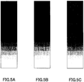
- FIG. 5A illustrates an example of original image data input to the thermal printer 100.
- the original image data has 16 gradation levels that are proportional to the dot area ratio.
- FIG. 5B illustrates an example of a printed image obtained by printing the original image data of FIG. 5A based on Table 1.
- FIG. 6 is a graph illustrating a relationship between the gradation level and the reflectance in the original image data of FIG. 5A and the printed image of FIG. 5B .
- the reflectance of a black color of an image (gradation level 15) is 1%
- the optical density is 2.00.
- the optical density of a black color in an actually-printed image does not reach 2.00.
- the saturation density is about 1.15
- the reflectance of the black color at gradation level 15 becomes 7%. Therefore it is assumed that a condition where the corresponding reflectance is 7% corresponds to a dot area ratio of 100%.
- the reflectances of the printed image are also slightly higher than the reflectances of the original image data at other gradation levels. Therefore, an image may be printed using a gradation table where energy values for respective gradation levels are set, such that the reflectance of the printed image at each gradation level equals the reflectance of the original image data within a range of reflectance that is reproducible on a recording medium.
- FIG. 7 is a graph illustrating a relationship between the gradation level and the reflectance in a case where such a gradation table is used.
- the reflectance of the printed image at gradation level 15 (7%) is different from the reflectance of the original image data
- the reflectances of the printed image and of the original image data are substantially the same at gradation levels 0 through 14.
- the gradation table stores energy values corresponding to the reflectances in FIG. 7 in association with each gradation level.
- FIG. 5C illustrates an example of a printed image printed using this type of gradation table.
- the thermal printer 100 may be configured to store multiple gradation tables in the RAM 11, and to allow a user to select one of the gradation tables for printing. The user can print an image with desired gradation characteristics by selecting a gradation table suitable for the image to be printed.
- the RAM 11 may store gradation tables with different numbers of gradation levels as exemplified by Tables 1-3, and/or gradation tables where the same number of gradation levels are defined but different energy values are specified for each of the gradation levels. Further, the RAM 11 may store a gradation table where energy values are set for gradation levels such that gradations are easily recognizable by human eyes, based on a relationship between the gradation level and the reflectance of an image expressed by a logarithmic function ( FIG. 8 ) like the relationship between the Munsell value and the reflectance.
- the MCU 10 controls the energy applied to the heating elements R based on a gradation table selected, for example, by a user.
- the MCU 10 transfers control data for controlling the heating elements to the shift register 14 so that energy corresponding to the gradation levels of image data is applied to each heating element.
- the MCU 10 transfers control data corresponding to gradation levels 1 through 15 for 15 times for each print line to apply energy corresponding to gradation levels to the respective heating elements R.
- a data transfer time for each line is 128 ⁇ s when the data transfer rate of the MCU 10 is 5 MHz. Accordingly, when the resolution of image data is 200 dpi (8 dot/mm), the printing speed is reduced to 60 mm/sec.
- the number of times data is transferred from the MCU 10 is reduced and the printing speed is increased by using a data transfer method described below.
- Energy corresponding to 16 gradation levels can be applied to the heating elements R by setting energy levels 0 through 15 by dividing an energy range of 0% through 100% into 16 equal parts as indicated by Table 4, and a 16-gradation-level image can be printed by transferring control data only four times.
- the MCU 10 transfers control data four times to the heating elements to apply energy with energy levels 0 through 15 corresponding to the gradation levels 0 through 15.
- the MCU 10 firstly sends first control data indicating ON or OFF of 53.3% energy, then sends second control data indicating ON or OFF of 26.7% energy, then sends third control data indicating ON or OFF of 13.3% energy, and finally sends fourth control data indicating ON or OFF of 6.7% energy.
- the heating element R1 is used to print an image of gradation level 7, energy of 46.7% corresponding to energy level 7 needs to be applied to the heating element R1.
- the MCU 10 sends the first control data (OFF), the second control data (ON), the third control data (ON), and the fourth control data (ON) for the heating element R1 based on Table 4.
- a total of 46.7% energy (26.7%+13.3%+6.7%) is applied to the heating element R1.
- energy corresponding to gradation levels can be applied to the heating elements by transferring control data four times such that control data indicate ON and OFF of different amounts of energy.
- the data transfer described above can reduce the number of data transfer from the MCU 10 to the shift register 14 and enables high-speed printing.
- Table 1 the minimum difference between energy values set for two adjacent gradation levels is 3.2%.
- the energy values corresponding to the gradation levels in Table 1 can be associated with energy levels in Table 5 to set a gradation-energy table of Table 6.
- 25.9% energy corresponding to gradation level 1 in Table 1 is close to 25.8% energy corresponding to energy level 8 in Table 5, and can be associated with energy level 8.
- a 16-gradation-level image can be printed by using energy values corresponding to the energy levels associated with the gradation levels.
- a 16-gradation-level image can be printed by transferring control data five times for each print line.
- the MCU 10 transfers control data five times based on Table 7 to apply energy corresponding to the gradation levels to the heating elements R.
- the MCU 10 sends first control data indicating ON or OFF of 51.6% energy, sends second control data indicating ON or OFF of 25.8% energy, sends third control data indicating ON or OFF of 12.9% energy, sends fourth control data indicating ON or OFF of 6.5% energy, and finally sends fifth control data indicating ON or OFF of 3.2% energy for each heating element.
- the MCU 10 sends the first control data (OFF), the second control data (ON), the third control data (ON), the fourth control data (OFF), and the fifth control data (OFF) based on Table 7. As a result, a total of 38.7% energy (25.8%+12.9%) is applied to the heating element.
- the thermal printer 100 can reduce the number of data transfer from the MCU 10 to the shift register 14 and can perform high-speed printing.
- an energy level table including 2 m energy levels (m is an integer greater than n) is set based on the minimum energy difference between the gradation levels in the gradation table.
- the MCU 10 can apply energy corresponding to gradation levels to the heating elements R by transferring control data of different amounts of energy "m" times to the shift register 14.
- Table 8 indicates an exemplary relationship between the number of times control data is transferred from the MCU 10 to the shift register 14 (transfer count) and the amounts of energy (energy values) represented by respective sets of control data.
- E 1 1 2 ⁇ 2 1 ⁇ m ⁇ 100
- an energy value represented by control data transferred at the second or subsequent time is set to one half (1/2) of the energy value represented by control data transferred at the previous time.
- the MCU 10 transfers control data separately for each of the printing blocks: heating elements R1-R160 (first block), heating elements R161-R320 (second block), heating elements R321-R480 (third block), and heating elements R481-R640 (fourth block).
- the MCU 10 When transferring control data five times for each print line, the MCU 10 generates five sets of 640-bit control data (DATA 1 through DATA 5) for the heating elements R as illustrated in FIG. 9A . Then, the MCU 10 divides each set of the Nth control data into four sets of 160-bit control data (DATA N-1 through DATA N-4) corresponding to the printing blocks.
- the MCU 10 transfers first control data through fifth control data to the shift register 14 in sequence for each printing block.
- the MCU 10 transfers control data DATA 1-1 through control data DATA 5-1 for the first block consecutively.
- the MCU 10 transfers control data DATA 1-2 through control data DATA 5-2 for the second block consecutively.
- the MCU 10 transfers control data DATA 1-3 through control data DATA 5-3 for the third block consecutively, and then transfers control data DATA 1-4 through control data DATA 5-4 for the fourth block consecutively.
- the control data transferred to the shift register 14 is transferred to the latch register 16, and then sent to the ICs corresponding to the heating elements R.
- the MCU 10 also sends STB 1 through STB4 in sequence to the ICs at the timings when power is supplied to the respective printing blocks.
- power is supplied to each printing block.
- the amount of energy to be applied to each heating element is controlled by power-supply period for which power is supplied to each heating element.
- the power-supply period is controlled by an input period for which STB signal is on.
- STB1 through STB4 are transferred for one printing block in succession by changing the input period based on the control data such that the energy amount set for each data transfer in Table 7 is applied to the corresponding heating elements.
- a power-supply interval (a time period between an end of a previous power supply and a start of next power supply) of the heating elements in the printing block can be made constant, and variation in print density due to variation in the power-supply interval can be reduced.
- the density of a printed image may vary depending on the type of recording medium used. This is because the amount of energy necessary to produce color varies depending on recording media.
- maximum values of energy applied to the heating elements R at the maximum gradation level are set for different types of recording media. By setting maximum energy values for different types of recording media, images with constant quality can be printed regardless of the types of recording media.
- Table 9 is an example of an energy table stored in the RAM 11 where maximum energy values E 0 (P) are set for respective types of paper P.
- E 0 the energy E 0 applied to the heating elements R at the maximum gradation level
- the MCU 10 obtains, from the RAM 11, the maximum energy value E 0 (P) corresponding to the type of paper P to be used.
- the type of paper P may be determined based on, for example, a parameter preset in the thermal printer 100, or a parameter received by the thermal printer 100 together with print data.
- the MCU 10 sends various signals to the shift register 14 to apply energy set in a gradation table to the heating elements R.
- Table 9 PAPER P E 0 (P) [mJ/mm 2 ]
- one or more voltage correction values k V (V) for correcting the amount of energy applied to the heating elements R are set and stored in the RAM 11.
- the voltage correction values k V (V) are set based on a voltage V applied by the power supply 17 to the heating elements R.
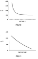
- FIG. 10 is a graph illustrating a relationship between the voltage V and the voltage correction value k V (V).
- the MCU 10 obtains a voltage correction value k V (V) corresponding to the voltage V applied by the power supply 17 from the RAM 11 to correct the amount of energy to be applied to the heating elements R.
- the MCU 10 supplies power to heating elements by transferring control data multiple times for each print line.
- the number of heating elements to which power is supplied may vary each time control data is transferred, and a voltage drop may occur when power is supplied to a large number of heating elements. Therefore, the timing to correct the amount of energy based on the voltage correction value k V (V) needs to be changed depending on the voltage of power supply 17. Because the amount of energy hardly varies in a high-voltage range, the amount of 100% energy is corrected for each print line when the thermal printer 100 is used with a high-voltage system.
- the thermal printer 100 when used with a low-voltage system such as a battery, the amount of energy varies greatly depending on the voltage, and the amount of energy needs to be corrected based on the number of heating elements to which power is supplied. Accordingly, in this case, the amount of energy is corrected each time power is supplied to the heating elements.
- the temperature of the heating element after application of energy may vary due to an influence of the temperature of the thermal head where the heating element is provided. Accordingly, even when image data with the same density is used, images with different density levels may be printed.
- one or more temperature correction values k T (T) for correcting the energy amount applied to the heating elements R may be set and stored in the RAM 11.
- the temperature correction values k T (T) are set based on a temperature T of the thermal head measured by the thermistor 12.
- FIG. 11 is a graph illustrating a relationship between the temperature T and k T (T).
- the temperature correction value k T (T) is set at a small value in a high-temperature range and increases as the temperature T decreases.
- the MCU 10 obtains a temperature correction value k T (T) corresponding to the measured temperature T from the RAM 11 to correct the amount of 100% energy to be applied to the heating elements R.
- correction of the energy amount based on the temperature correction value k T (T) may be performed at any given timing, e.g., at 1 ms intervals.
- the temperature of the heating element after application of energy may vary because the degree to which the heating element radiates heat and cools varies depending on a period of time from an end of power supply for the previous print line to a start of power supply for the next print line (radiation time t). Accordingly, even when image data with the same density is used, images with different density levels may be printed.
- one or more rate correction values k S (t) for correcting the amounts of energy applied to the heating elements R may be set and stored in the RAM 11.
- the rate correction values k S (t) are set based on the radiation time t of the heating elements R.
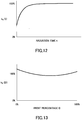
- FIG. 12 is a graph illustrating a relationship between the radiation time t and the rate correction value k S (t).
- the rate correction value k S (t) becomes smaller as the radiation time t decreases.
- the MCU 10 obtains a rate correction value k S (t) corresponding to the radiation time t from the RAM 11 for each print line, and corrects the amount of 100% energy to be applied to the heating elements R.
- the temperature of the heating element after application of energy may vary depending on whether power is supplied at the previous print line and/or whether power is supplied to an adjacent heating element. Accordingly, even when image data with the same density is used, images with different density levels may be printed.
- one or more print percentage correction values k D (D) to correct the amount of energy applied to the heating elements R may be set and stored in the RAM 11 in association with print percentages D.
- the print percentage correction values k D (D) are determined based on a print percentage D.
- FIG. 13 is a graph illustrating a relationship between the print percentage D and the print percentage correction value k D (D).
- the MCU 10 obtains a print percentage correction value k D (D) corresponding to a print percentage D from the RAM 11, and corrects the amount of energy to be applied to the heating elements R.
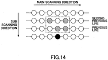
- the print percentage D is calculated based on six dots that are surrounded by a broken line.
- the six dots are in two previous lines that immediately precede, in the sub scanning direction, a line where a print dot indicated by a black circle exists.
- the print dot corresponds to one of the heating elements R1-R640.
- Two dots among the six dots are at the same position as the print dot in the main scanning direction, and four other dots are adjacent to these two dots.
- hatched circles indicate printed dots
- white circles indicate non-printed dots in which power is not supplied to the corresponding heating element.
- the MCU 10 obtains a print percentage correction value k D (D) for each print dot from the RAM 11 based on the calculated print percentage D, and corrects the amount of energy to be applied to the heating element corresponding to the print dot based on the obtained print percentage correction value k D (D).
- the calculation of the print percentage D is not limited to the above described method.
- the amount of energy applied to the heating elements R is corrected based on at least one of the voltage correction value k V (V), the temperature correction value k T (T), the rate correction value k S (t), and the print percentage correction value k D (D).
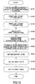
- FIG. 15 is a flowchart illustrating an image data process. When image data is input to the thermal printer 100, a process illustrated in FIG. 15 is performed.
- the MCU 10 obtains a maximum energy value E 0 (P) corresponding to the type of paper used for printing from Table 9.
- the MCU 10 repeats S102 through S109 for the number of print lines (print line count Lp) in the image data.
- each print line includes 640 dots, and S103 through S108 are repeated 640 times for each print line because values are calculated for the respective dots. However, when such calculation is not necessary, repetition of those processes may be omitted.
- the MCU 10 calculates, for the corresponding print dot or heating element, a print percentage D of two print lines immediately preceding the print dot.
- the MCU 10 obtains a print percentage correction value k D (D) corresponding to the calculated print percentage D from the RAM 11.
- the MCU 10 corrects the gradation level of the print dot based on k D (D) obtained at S105. For example, when the gradation level of the print dot is 9 and k D (D) is 110%, the MCU 10 corrects the gradation level of the print dot to 10 ( ⁇ 9 x 1.1).
- the MCU 10 obtains an energy level corresponding to the gradation level corrected at S106 from the gradation-energy table (Table 6). For example, when the corrected gradation level is 10, the MCU 10 obtains an energy level 18.
- the MCU 10 repeats S104 through S107 for the number of dots in each print line and repeats S103 through S108 for the number of print lines to obtain energy levels for all print dots in image data to be printed.
- FIG. 16 is a flowchart illustrating an exemplary printing process.
- the MCU 10 When image data is input to the thermal printer 100, the MCU 10 performs the process of FIG. 15 , and then performs a printing process illustrated by FIG. 16 .
- the MCU 10 repeats S201 through S217 for the number of print lines (Lp) in the image data.
- the MCU 10 obtains a temperature T of the thermal head from the thermistor 12.
- the MCU 10 obtains a temperature correction value k T (T) corresponding to the obtained temperature T from the RAM 11.
- the MCU 10 obtains a power-supply start time.
- the MCU 10 calculates a radiation time t from a power-supply end time of a previous print line to the power-supply start time obtained at S204.
- the MCU 10 obtains a rate correction value k S (t) corresponding to the calculated radiation time t from the RAM 11.
- the MCU 10 corrects the maximum energy value E 0 (P) obtained at S101 based on k T (T) and k S (t) according to formula (3) to obtain a corrected maximum energy value E to be applied to the heating elements R, and converts the corrected maximum energy value E into a power-supply period.
- E E 0 P ⁇ k T T ⁇ k S t
- the MCU 10 repeats S208 through S215 for the number of times power is supplied to the heating elements R (power supply count).
- the power supply count per print line is five.
- the MCU 10 calculates a power-supply period t1 corresponding to the amount of energy to be supplied to heating elements each time. For example, when the power supply count is five as indicated by Table 7, the MCU 10 calculates t1 such that an amount of energy corresponding to 51.6% of the corrected maximum energy value E obtained at S207 is applied to heating elements at the first time. For the second and subsequent times, the MCU 10 calculates the power-supply period t1 such that amounts of energy corresponding to 25.8%, 12.9%, 6.5%, and 3.2% of the corrected maximum energy value E are applied sequentially to heating elements.
- the power-supply period is controlled by changing the length of time for which the STB signal is turned on.
- the MCU 10 starts supplying power to the heating elements.
- the MCU 10 obtains a voltage V being supplied from the power supply 17 to the heating elements.
- the MCU 10 obtains a voltage correction value k V (V) corresponding to the voltage V from the RAM 11.
- the MCU 10 corrects the power-supply period t1 calculated at S209 based on the voltage correction value k V (V) according to formula (4) below.
- t 1 t 1 ⁇ k V V
- the MCU 10 stops supplying power to the heating elements when the corrected power-supply period t1 passes after start of the power supply.
- the power-supply period t1 corresponds to a length of time for which the STB signal is turned on.
- the MCU 10 controls t1 for each time so that the amounts of energy indicated by energy levels corresponding to gradation levels of image data are applied to the corresponding heating elements R1-R640.
- the MCU 10 When the power is supplied to the heating elements for the predetermined number of times and printing of one print line is completed, the MCU 10 obtains a power-supply end time at S216. The MCU 10 calculates a radiation time t for the next print line at S205 based on the obtained power-supply end time.
- S201 through S217 are repeated for the print line count Lp in the image data, and printing of the image data on a recording medium is completed.
- the thermal printer 100 performs the image data process and then performs the printing process described above to print an image on a recording medium.
- the amount of energy to be applied to each heating element is set based on a dot area ratio to improve the gradation reproducibility of a printed image. Also in the present embodiment, the number of times control data is transferred is reduced so that a high-resolution image can be printed at a high speed. Further in the present embodiment, the amount of energy to be applied to heating elements is corrected based on at least one of the voltage V applied by the power supply 17 to the heating elements, the temperature T of the thermal head, the radiation time t, and the print percentage D so that images with constant quality can be printed regardless of changes in various conditions.
- the second control data through the fifth control data are "OFF". Accordingly, no voltage is applied to the heating element and no image is printed during a period that the second control data through the fifth control data are output.
- the first control data is "OFF”. Accordingly, no voltage is applied to the heating element during a period that the first control data is output.
- the non-printed area may appear as a white streak in the image.
- the dots are printed with energy level 15 and then with energy level 16.
- the second control data through the fifth control data are "ON". Accordingly, a voltage is applied to the heating element and an image is printed during a period that the second control data through the fifth control data are output. Also, in the printing with energy level 16 following the printing with energy level 15, the first control data is "ON”. Accordingly, a voltage is applied to the heating element and an image is printed during a period that the first control data is output.
- the amount of energy becomes equivalent to energy level 31 (gradation level 15) and a printed area is formed. Accordingly, in the portion of the image where a dot with gradation level 7 and a dot with gradation level 8 are consecutively arranged, the printed area may appear as a black streak in the image.
- a gradation-energy table of the second embodiment (Table 10) multiple energy levels are set for each gradation level of the "current" print dot in the current print line in association with gradation levels of the "previous” print dot located in the previous print line in the same position as the current print dot in the main scanning direction so that printing with energy level 15 and printing with energy level 16 are not performed consecutively.
- energy level 15 is set in association with the previous print dot with gradation levels 0-7 and 9-15
- energy level 17 is set in association with the previous print dot with gradation level 8.
- energy level 16 is set in association with the previous print dot with gradation levels 0-6 and 8-15
- energy level 14 is set in association with the previous print dot with gradation level 7.
- the same energy levels as those in Table 6 are set regardless of the gradation levels of the previous print dot.
- a gradation-energy table different from the described gradation-energy table may be used depending on the number of gradation levels of an image to be printed and data transfer conditions in a control table.
- FIG. 18A illustrates the data transfer timing and the power-supply timing in a case where dots with gradation level 8 (energy level 16) appear consecutively in printing a 16-gradation-level image using Table 7.
- FIG. 18B illustrates the data transfer timing and the power-supply timing in a case where dots with gradation level 7 (energy level 15) appear consecutively.
- the data transfer time is 120 ⁇ s
- the printing interval is 890 ⁇ s (printing speed: about 140 mm/sec)
- the power supply time for 100% energy is 640 ⁇ s.
- Numerals in FIG. 18A indicate time ( ⁇ s).
- the heat radiation amount of a heating element varies depending on the length of the quiescent period between the end of power supply for the previous print line and the start of power supply for the next print line. Accordingly, even when the same amount of energy is applied to a heating element, the temperature of the heating element after the application of energy varies depending on the length of the quiescent period.
- the quiescent period in the consecutive printing with energy level 15 (470 ⁇ s) is shorter than the quiescent period in the continuous printing with energy level 16 (570 ⁇ s).
- the temperature of heating elements tends to more easily increase due to residual heat remaining after printing the previous print line compared with the consecutive printing with energy level 16. Therefore, the print density in the consecutive printing with energy level 15 may become higher than the print density in the consecutive printing with energy level 16 in certain case. Also, the influence of the residual heat of heating elements remaining after printing the previous line increases as the printing speed increases.
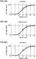
- FIGs. 19A through 19C are graphs illustrating relationships between an energy level and a dot area ratio of an image observed with different printing speeds.
- FIG. 19A illustrates a case where the printing speed is low
- FIG. 19B illustrates a case where the printing speed is medium
- FIG. 19C illustrates a case where the printing speed is high.
- the dot area ratio at energy level 15 is greater than the dot area ratio at energy level 16. That is, the dot area ratios formed at energy levels 15 and 16 are reversed.
- the dot area ratio at energy level 15 is greater than the dot area ratio at energy level 16, and the dot area ratio at energy level 19 is greater than the dot area ratio at energy level 20.
- the dot area ratios formed at energy levels 15 and 16 are reversed, and the dot area ratios formed at energy levels 19 and 20 are reversed.
- the dot area ratio at a lower energy level may become greater than that at a higher energy level.
- energy level 16 is omitted from a gradation-energy table of Table 11 among one of energy levels 15 and 16 at which print densities may be reversed depending on printing speeds.
- energy level 19 is omitted from Table 11 among energy levels 19 and 20.
- energy levels are set such that the print density gradually changes in accordance with changes in the gradation level regardless of the printing speed. Therefore, an image with high gradation reproducibility can be printed without causing reversal of print densities at any printing speed.
- Energy levels different from those in the gradation-energy table of the present embodiment may also be used depending on, for example, the number of gradation levels of an image to be printed and data transfer conditions in a control table.
- all of the images are printed with a target gradation scale of one of the images by converting the original gradation levels of other images in original gradation scales into target gradation levels in the target gradation scale of the one of the images.
- the original gradation levels of the first image in the 4-level gradation scale original gradation scale
- target gradation scale target gradation scale
- the original gradation levels of the second image in the 16-level gradation scale may be converted into target gradation levels in the 4-level gradation scale (target gradation scale), to print the first and second images using the 4-level gradation scale.
- gradation levels are converted using formula (5).
- TARGET GRADATION LEVEL NO .
- other original gradation levels of the second image can be converted into target gradation levels in the 4-level gradation scale as illustrated in Table 13.
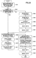
- FIG. 20 is a flowchart illustrating an image data process according to the fourth embodiment. When image data is input to the thermal printer 100, a process illustrated in FIG. 20 is performed.
- the MCU 10 obtains the number of gradation levels (set value) used for printing.
- the MCU 10 proceeds to S308.
- the MCU 10 repeats S303 through S307 to convert the gradation levels of respective dots in each line of the image.
- S303 through S307 are repeated y times
- process of S304 through S306 are repeated x times for each line of the image.
- the MCU 10 obtains a target gradation level for each dot in the image using formula (5).
- the MCU 10 obtains a maximum energy value E 0 (P) corresponding to the type of paper used for printing from Table 9.
- the MCU 10 repeats S309 through S316 for the number of print lines in the image.
- the MCU 10 repeats S310 through S315 for the number of print dots in each print line.
- the MCU 10 calculates a print percentage D of two print lines immediately preceding the print dot.
- the MCU 10 obtains a print percentage correction value k D (D) corresponding to the calculated print percentage D from the RAM 11.
- the MCU 10 corrects the gradation level of the print dot based on k D (D) obtained at S312.
- the MCU 10 obtains an energy level corresponding to the gradation level corrected at S313 from a gradation-energy table.
- Multiple images with different gradation scales can be printed by performing the process described above before performing a printing process.
- a first image with a 4-level gradation scale and a second image with a 16-level gradation scale are to be printed
- both of the first image and the second image is printed using the 16-level gradation scale by converting the original gradation levels of the first image into target gradation levels in the 16-level gradation scale.
- the original gradation levels of the second image may be converted into target gradation levels in the 4-level gradation scale, to print the first and second images with the 4-level gradation scale. This makes it possible to print the images at high speed.
- all of the images can be printed using a gradation scale of one of the images by converting the original gradation levels of other images into target gradation levels in the gradation scale of the one of the images.
- multiple images with different gradation scales can be printed in the same area, by converting the original energy levels of other images in original energy scales into target energy levels in the target energy scale of the one of the images.
- the original energy levels of the second image in the 32-level energy scale may be converted into target energy levels in the 8-level energy scale (target energy scale) of the first image, and the first and second images are printed with the 8-level energy scale.
- energy levels are converted using formula (6).
- TARGET ENERGY LEVEL NO .
- the second image is printed with four energy levels (0, 3, 4, 7).
- the second image is printed with seven energy levels (0, 2, 3, 4, 5, 6, 7) as in Table 15.
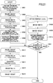
- FIG. 21 is a flowchart illustrating an image data process according to the fifth embodiment. When image data is input to the thermal printer 100, a process illustrated in FIG. 21 is performed.
- the MCU 10 obtains a maximum energy value E 0 (P) corresponding to the type of paper used for printing from Table 9.
- the MCU 10 converts gradation levels of an image into energy levels.
- the MCU 10 repeats S402 through S409 for the number of times corresponding to the height of the image.
- the MCU 10 repeats S403 through S408 for the number of dots in each print line of the image.
- S402 through S409 are repeated y times
- S403 through S408 are repeated x times for each print line.
- the MCU 10 calculates a print percentage D of two print lines immediately preceding the print dot.
- the MCU 10 obtains a print percentage correction value k D (D) corresponding to the calculated print percentage D from the RAM 11.
- the MCU 10 corrects the gradation level of the print dot based on k D (D) obtained at S405.
- the MCU 10 obtains an energy level corresponding to the gradation level corrected at S406 from a gradation-energy table.
- the MCU 10 obtains the number of energy levels (set value) used for printing.
- the MCU 10 ends the process.
- the MCU 10 repeats S412 through S416 to convert the energy levels of respective dots in each line of the image.
- the MCU 10 obtains a target energy level for each dot in the image using formula (6).
- Multiple images with different gradation scales can be printed with the process described above.
- image data including a first image with a 4-level gradation scale and a second image with a 16-level gradation scale is to be printed
- the entire image can be printed with a 32-level energy scale by converting the original energy levels of the first image in an 8-level energy scale into target energy levels in the 32-level energy scale, or with a 8-level energy scale by converting the original energy levels of the second image in the 32-level energy scale into target energy levels in the 8-level energy scale.
- the thermal printer of this embodiment can perform high-speed printing. Also, compared with a method where gradation levels are converted, this embodiment improves the gradation reproducibility of the second image.
- all of the images can be printed using an energy scale of one of the images by converting the energy levels of other images into energy levels in the energy scale of the one of the images.
Landscapes
- Electronic Switches (AREA)
- Color, Gradation (AREA)
Applications Claiming Priority (2)
| Application Number | Priority Date | Filing Date | Title |
|---|---|---|---|
| JP2016133522A JP2018001653A (ja) | 2016-07-05 | 2016-07-05 | サーマルプリンタ |
| EP17177964.8A EP3266616B1 (fr) | 2016-07-05 | 2017-06-26 | Imprimante thermique |
Related Parent Applications (2)
| Application Number | Title | Priority Date | Filing Date |
|---|---|---|---|
| EP17177964.8A Division EP3266616B1 (fr) | 2016-07-05 | 2017-06-26 | Imprimante thermique |
| EP17177964.8A Division-Into EP3266616B1 (fr) | 2016-07-05 | 2017-06-26 | Imprimante thermique |
Publications (2)
| Publication Number | Publication Date |
|---|---|
| EP3326826A1 true EP3326826A1 (fr) | 2018-05-30 |
| EP3326826B1 EP3326826B1 (fr) | 2020-08-12 |
Family
ID=59227584
Family Applications (2)
| Application Number | Title | Priority Date | Filing Date |
|---|---|---|---|
| EP18152145.1A Active EP3326826B1 (fr) | 2016-07-05 | 2017-06-26 | Imprimante thermique |
| EP17177964.8A Active EP3266616B1 (fr) | 2016-07-05 | 2017-06-26 | Imprimante thermique |
Family Applications After (1)
| Application Number | Title | Priority Date | Filing Date |
|---|---|---|---|
| EP17177964.8A Active EP3266616B1 (fr) | 2016-07-05 | 2017-06-26 | Imprimante thermique |
Country Status (4)
| Country | Link |
|---|---|
| US (1) | US10252543B2 (fr) |
| EP (2) | EP3326826B1 (fr) |
| JP (1) | JP2018001653A (fr) |
| CN (1) | CN107571634B (fr) |
Families Citing this family (4)
| Publication number | Priority date | Publication date | Assignee | Title |
|---|---|---|---|---|
| TWI666126B (zh) * | 2018-09-28 | 2019-07-21 | 謙華科技股份有限公司 | 打印頭裝置及列印方法 |
| JP7253390B2 (ja) * | 2019-01-18 | 2023-04-06 | 日本電産サンキョー株式会社 | 印刷装置、印刷方法およびプログラム |
| JP7698956B2 (ja) | 2021-02-15 | 2025-06-26 | 株式会社サトー | プリンタ、印字制御方法、プログラム |
| JP2024140695A (ja) * | 2023-03-28 | 2024-10-10 | キヤノン株式会社 | 制御装置、インクジェット記録装置、方法、及びプログラム |
Citations (4)
| Publication number | Priority date | Publication date | Assignee | Title |
|---|---|---|---|---|
| JPH04220358A (ja) | 1990-12-20 | 1992-08-11 | Fujitsu Ltd | サーマルプリンタ |
| US6674546B1 (en) * | 1998-12-25 | 2004-01-06 | Toshiba Tec Kabushiki Kaisha | Image processing method according to sort of image and image processing apparatus |
| JP2006121153A (ja) * | 2004-10-19 | 2006-05-11 | Konica Minolta Medical & Graphic Inc | 面積階調画像形成方法及び面積階調画像形成装置 |
| JP2006335009A (ja) * | 2005-06-03 | 2006-12-14 | Max Co Ltd | サーマルプリンタ |
Family Cites Families (23)
| Publication number | Priority date | Publication date | Assignee | Title |
|---|---|---|---|---|
| JPH0825293B2 (ja) | 1986-05-30 | 1996-03-13 | 松下電器産業株式会社 | 階調プリンタにおける濃度特性測定方法 |
| JPH0462070A (ja) | 1990-06-25 | 1992-02-27 | Sanyo Electric Co Ltd | 熱転写ビデオプリンタ |
| JP2928628B2 (ja) * | 1990-11-30 | 1999-08-03 | 株式会社日立製作所 | 感熱記録装置 |
| JPH0624027A (ja) * | 1992-01-28 | 1994-02-01 | Nec Home Electron Ltd | 蓄熱補正回路 |
| JPH0626838A (ja) * | 1992-07-13 | 1994-02-04 | Toshiba Corp | 網点面積率測定装置及び網点面積率測定方法 |
| US5644351A (en) * | 1992-12-04 | 1997-07-01 | Matsushita Electric Industrial Co., Ltd. | Thermal gradation printing apparatus |
| JPH0776115A (ja) * | 1993-09-08 | 1995-03-20 | Sony Corp | 熱転写プリンタ |
| JP2967254B2 (ja) * | 1993-09-10 | 1999-10-25 | セイコーインスツルメンツ株式会社 | 記録装置及び記録方法 |
| JP3538361B2 (ja) | 2000-04-03 | 2004-06-14 | 株式会社ヤマトヤ商会 | カラー原稿の色再現性に優れた4色カラー網点印刷画像を製作するための各色版の網点面積比(c,m,y,bk)の設定法 |
| US6819347B2 (en) * | 2001-08-22 | 2004-11-16 | Polaroid Corporation | Thermal response correction system |
| CN1403295A (zh) * | 2001-09-06 | 2003-03-19 | 诚研科技股份有限公司 | 热打印头的打印方法 |
| JP2006074668A (ja) | 2004-09-06 | 2006-03-16 | Konica Minolta Medical & Graphic Inc | 面積階調画像の形成方法及び形成装置 |
| US7324125B2 (en) | 2004-12-10 | 2008-01-29 | Intermec Ip Corp. | Method for automatic adjustment of media settings for a printer |
| JP2006224419A (ja) | 2005-02-17 | 2006-08-31 | Seiko Epson Corp | 印刷装置、印刷プログラム、印刷方法、および画像処理装置、画像処理プログラム、画像処理方法、ならびに前記プログラムを記録した記録媒体 |
| JP2006279152A (ja) | 2005-03-28 | 2006-10-12 | Konica Minolta Medical & Graphic Inc | キャリブレーション方法及び画像変換方法 |
| JP2007223161A (ja) * | 2006-02-23 | 2007-09-06 | Star Micronics Co Ltd | サーマルプリンタ及びその制御方法 |
| JP5094298B2 (ja) | 2007-09-14 | 2012-12-12 | キヤノン株式会社 | カラー画像形成装置、カラー画像形成装置における色調整方法 |
| US8009184B2 (en) * | 2008-06-13 | 2011-08-30 | Zink Imaging, Inc. | Thermal response correction system for multicolor printing |
| JP5647822B2 (ja) * | 2009-07-24 | 2015-01-07 | ローム株式会社 | サーマルプリントヘッド、サーマルプリンタおよびプリンタシステム |
| US8414102B2 (en) | 2011-08-11 | 2013-04-09 | Xerox Corporation | In situ calibration of multiple printheads to reference ink targets |
| JP2014079882A (ja) * | 2012-10-12 | 2014-05-08 | Fujitsu Component Ltd | サーマルプリンタ |
| US8960839B1 (en) | 2014-05-14 | 2015-02-24 | Xerox Corporation | System and method for spatial dependent correction for images printed with multiple drop parameters |
| JP2016198955A (ja) * | 2015-04-10 | 2016-12-01 | 富士通コンポーネント株式会社 | サーマルプリンタ |
-
2016
- 2016-07-05 JP JP2016133522A patent/JP2018001653A/ja active Pending
-
2017
- 2017-06-15 US US15/623,769 patent/US10252543B2/en active Active
- 2017-06-26 EP EP18152145.1A patent/EP3326826B1/fr active Active
- 2017-06-26 EP EP17177964.8A patent/EP3266616B1/fr active Active
- 2017-06-28 CN CN201710511945.3A patent/CN107571634B/zh active Active
Patent Citations (4)
| Publication number | Priority date | Publication date | Assignee | Title |
|---|---|---|---|---|
| JPH04220358A (ja) | 1990-12-20 | 1992-08-11 | Fujitsu Ltd | サーマルプリンタ |
| US6674546B1 (en) * | 1998-12-25 | 2004-01-06 | Toshiba Tec Kabushiki Kaisha | Image processing method according to sort of image and image processing apparatus |
| JP2006121153A (ja) * | 2004-10-19 | 2006-05-11 | Konica Minolta Medical & Graphic Inc | 面積階調画像形成方法及び面積階調画像形成装置 |
| JP2006335009A (ja) * | 2005-06-03 | 2006-12-14 | Max Co Ltd | サーマルプリンタ |
Also Published As
| Publication number | Publication date |
|---|---|
| EP3326826B1 (fr) | 2020-08-12 |
| CN107571634A (zh) | 2018-01-12 |
| CN107571634B (zh) | 2019-09-06 |
| EP3266616A2 (fr) | 2018-01-10 |
| US20180009233A1 (en) | 2018-01-11 |
| JP2018001653A (ja) | 2018-01-11 |
| EP3266616A3 (fr) | 2018-04-04 |
| EP3266616B1 (fr) | 2020-01-01 |
| US10252543B2 (en) | 2019-04-09 |
Similar Documents
| Publication | Publication Date | Title |
|---|---|---|
| EP3326826B1 (fr) | Imprimante thermique | |
| US20160100079A1 (en) | Multilevel halftoning module with non-uniformity compensation | |
| US4801948A (en) | Thermal recording apparatus with resistance compensation | |
| US4774528A (en) | Thermal recording apparatus capable of gradation recording | |
| US4679055A (en) | Method and apparatus for thermal half-tone printing | |
| JPH11198452A (ja) | 画像補正方法 | |
| EP3078498B1 (fr) | Imprimante thermique | |
| US5666150A (en) | Non-uniformity correction for LED printhead in electrophotographic gray scale printing | |
| EP1292114A3 (fr) | Systéme et procédé pour la correction de gamma d'images en demi teintes | |
| JP7104763B2 (ja) | サーマルプリンタ | |
| KR940007012B1 (ko) | 칼라비디오프린터의고속프린팅방법및장치 | |
| KR20010030303A (ko) | 감열식 프린터의 헤드 콘트롤러 및 프린팅 방법 | |
| KR100882068B1 (ko) | 투과 조명형 표시판의 휘도 조정 방법 및 투과 조명형표시판 | |
| JPH08244265A (ja) | 中間調記録方法及び装置 | |
| JPH11115227A (ja) | 記録装置 | |
| KR0132879B1 (ko) | 열전사 프린터장치 | |
| KR0141118B1 (ko) | 비디오 프린터장치 | |
| JPH07314758A (ja) | サーマルヘッド駆動制御方法及び装置 | |
| JPH02160564A (ja) | 濃度階調プリンタの階調補正装置 | |
| JPH07314791A (ja) | 画像露光装置 | |
| JPH0691916A (ja) | 濃度階調制御型プリンタ | |
| JPH07132633A (ja) | サーマルヘッド駆動制御装置 | |
| JPH0564928A (ja) | 印写装置 | |
| JPH09220822A (ja) | サーマルプリンタ | |
| JPH02260969A (ja) | 中間調記録装置 |
Legal Events
| Date | Code | Title | Description |
|---|---|---|---|
| PUAI | Public reference made under article 153(3) epc to a published international application that has entered the european phase |
Free format text: ORIGINAL CODE: 0009012 |
|
| STAA | Information on the status of an ep patent application or granted ep patent |
Free format text: STATUS: THE APPLICATION HAS BEEN PUBLISHED |
|
| AC | Divisional application: reference to earlier application |
Ref document number: 3266616 Country of ref document: EP Kind code of ref document: P |
|
| AK | Designated contracting states |
Kind code of ref document: A1 Designated state(s): AL AT BE BG CH CY CZ DE DK EE ES FI FR GB GR HR HU IE IS IT LI LT LU LV MC MK MT NL NO PL PT RO RS SE SI SK SM TR |
|
| AX | Request for extension of the european patent |
Extension state: BA ME |
|
| STAA | Information on the status of an ep patent application or granted ep patent |
Free format text: STATUS: REQUEST FOR EXAMINATION WAS MADE |
|
| 17P | Request for examination filed |
Effective date: 20181120 |
|
| RBV | Designated contracting states (corrected) |
Designated state(s): AL AT BE BG CH CY CZ DE DK EE ES FI FR GB GR HR HU IE IS IT LI LT LU LV MC MK MT NL NO PL PT RO RS SE SI SK SM TR |
|
| STAA | Information on the status of an ep patent application or granted ep patent |
Free format text: STATUS: EXAMINATION IS IN PROGRESS |
|
| 17Q | First examination report despatched |
Effective date: 20190708 |
|
| GRAP | Despatch of communication of intention to grant a patent |
Free format text: ORIGINAL CODE: EPIDOSNIGR1 |
|
| STAA | Information on the status of an ep patent application or granted ep patent |
Free format text: STATUS: GRANT OF PATENT IS INTENDED |
|
| INTG | Intention to grant announced |
Effective date: 20200302 |
|
| GRAS | Grant fee paid |
Free format text: ORIGINAL CODE: EPIDOSNIGR3 |
|
| GRAA | (expected) grant |
Free format text: ORIGINAL CODE: 0009210 |
|
| STAA | Information on the status of an ep patent application or granted ep patent |
Free format text: STATUS: THE PATENT HAS BEEN GRANTED |
|
| AC | Divisional application: reference to earlier application |
Ref document number: 3266616 Country of ref document: EP Kind code of ref document: P |
|
| AK | Designated contracting states |
Kind code of ref document: B1 Designated state(s): AL AT BE BG CH CY CZ DE DK EE ES FI FR GB GR HR HU IE IS IT LI LT LU LV MC MK MT NL NO PL PT RO RS SE SI SK SM TR |
|
| REG | Reference to a national code |
Ref country code: CH Ref legal event code: EP |
|
| REG | Reference to a national code |
Ref country code: DE Ref legal event code: R096 Ref document number: 602017021737 Country of ref document: DE |
|
| REG | Reference to a national code |
Ref country code: IE Ref legal event code: FG4D |
|
| REG | Reference to a national code |
Ref country code: AT Ref legal event code: REF Ref document number: 1301181 Country of ref document: AT Kind code of ref document: T Effective date: 20200915 |
|
| REG | Reference to a national code |
Ref country code: LT Ref legal event code: MG4D |
|
| REG | Reference to a national code |
Ref country code: NL Ref legal event code: MP Effective date: 20200812 |
|
| PG25 | Lapsed in a contracting state [announced via postgrant information from national office to epo] |
Ref country code: GR Free format text: LAPSE BECAUSE OF FAILURE TO SUBMIT A TRANSLATION OF THE DESCRIPTION OR TO PAY THE FEE WITHIN THE PRESCRIBED TIME-LIMIT Effective date: 20201113 Ref country code: LT Free format text: LAPSE BECAUSE OF FAILURE TO SUBMIT A TRANSLATION OF THE DESCRIPTION OR TO PAY THE FEE WITHIN THE PRESCRIBED TIME-LIMIT Effective date: 20200812 Ref country code: HR Free format text: LAPSE BECAUSE OF FAILURE TO SUBMIT A TRANSLATION OF THE DESCRIPTION OR TO PAY THE FEE WITHIN THE PRESCRIBED TIME-LIMIT Effective date: 20200812 Ref country code: BG Free format text: LAPSE BECAUSE OF FAILURE TO SUBMIT A TRANSLATION OF THE DESCRIPTION OR TO PAY THE FEE WITHIN THE PRESCRIBED TIME-LIMIT Effective date: 20201112 Ref country code: SE Free format text: LAPSE BECAUSE OF FAILURE TO SUBMIT A TRANSLATION OF THE DESCRIPTION OR TO PAY THE FEE WITHIN THE PRESCRIBED TIME-LIMIT Effective date: 20200812 Ref country code: FI Free format text: LAPSE BECAUSE OF FAILURE TO SUBMIT A TRANSLATION OF THE DESCRIPTION OR TO PAY THE FEE WITHIN THE PRESCRIBED TIME-LIMIT Effective date: 20200812 Ref country code: NO Free format text: LAPSE BECAUSE OF FAILURE TO SUBMIT A TRANSLATION OF THE DESCRIPTION OR TO PAY THE FEE WITHIN THE PRESCRIBED TIME-LIMIT Effective date: 20201112 |
|
| REG | Reference to a national code |
Ref country code: AT Ref legal event code: MK05 Ref document number: 1301181 Country of ref document: AT Kind code of ref document: T Effective date: 20200812 |
|
| PG25 | Lapsed in a contracting state [announced via postgrant information from national office to epo] |
Ref country code: LV Free format text: LAPSE BECAUSE OF FAILURE TO SUBMIT A TRANSLATION OF THE DESCRIPTION OR TO PAY THE FEE WITHIN THE PRESCRIBED TIME-LIMIT Effective date: 20200812 Ref country code: NL Free format text: LAPSE BECAUSE OF FAILURE TO SUBMIT A TRANSLATION OF THE DESCRIPTION OR TO PAY THE FEE WITHIN THE PRESCRIBED TIME-LIMIT Effective date: 20200812 Ref country code: PL Free format text: LAPSE BECAUSE OF FAILURE TO SUBMIT A TRANSLATION OF THE DESCRIPTION OR TO PAY THE FEE WITHIN THE PRESCRIBED TIME-LIMIT Effective date: 20200812 Ref country code: RS Free format text: LAPSE BECAUSE OF FAILURE TO SUBMIT A TRANSLATION OF THE DESCRIPTION OR TO PAY THE FEE WITHIN THE PRESCRIBED TIME-LIMIT Effective date: 20200812 Ref country code: IS Free format text: LAPSE BECAUSE OF FAILURE TO SUBMIT A TRANSLATION OF THE DESCRIPTION OR TO PAY THE FEE WITHIN THE PRESCRIBED TIME-LIMIT Effective date: 20201212 |
|
| PG25 | Lapsed in a contracting state [announced via postgrant information from national office to epo] |
Ref country code: EE Free format text: LAPSE BECAUSE OF FAILURE TO SUBMIT A TRANSLATION OF THE DESCRIPTION OR TO PAY THE FEE WITHIN THE PRESCRIBED TIME-LIMIT Effective date: 20200812 Ref country code: CZ Free format text: LAPSE BECAUSE OF FAILURE TO SUBMIT A TRANSLATION OF THE DESCRIPTION OR TO PAY THE FEE WITHIN THE PRESCRIBED TIME-LIMIT Effective date: 20200812 Ref country code: DK Free format text: LAPSE BECAUSE OF FAILURE TO SUBMIT A TRANSLATION OF THE DESCRIPTION OR TO PAY THE FEE WITHIN THE PRESCRIBED TIME-LIMIT Effective date: 20200812 Ref country code: RO Free format text: LAPSE BECAUSE OF FAILURE TO SUBMIT A TRANSLATION OF THE DESCRIPTION OR TO PAY THE FEE WITHIN THE PRESCRIBED TIME-LIMIT Effective date: 20200812 Ref country code: SM Free format text: LAPSE BECAUSE OF FAILURE TO SUBMIT A TRANSLATION OF THE DESCRIPTION OR TO PAY THE FEE WITHIN THE PRESCRIBED TIME-LIMIT Effective date: 20200812 |
|
| REG | Reference to a national code |
Ref country code: DE Ref legal event code: R097 Ref document number: 602017021737 Country of ref document: DE |
|
| PG25 | Lapsed in a contracting state [announced via postgrant information from national office to epo] |
Ref country code: ES Free format text: LAPSE BECAUSE OF FAILURE TO SUBMIT A TRANSLATION OF THE DESCRIPTION OR TO PAY THE FEE WITHIN THE PRESCRIBED TIME-LIMIT Effective date: 20200812 Ref country code: AT Free format text: LAPSE BECAUSE OF FAILURE TO SUBMIT A TRANSLATION OF THE DESCRIPTION OR TO PAY THE FEE WITHIN THE PRESCRIBED TIME-LIMIT Effective date: 20200812 Ref country code: AL Free format text: LAPSE BECAUSE OF FAILURE TO SUBMIT A TRANSLATION OF THE DESCRIPTION OR TO PAY THE FEE WITHIN THE PRESCRIBED TIME-LIMIT Effective date: 20200812 |
|
| PLBE | No opposition filed within time limit |
Free format text: ORIGINAL CODE: 0009261 |
|
| STAA | Information on the status of an ep patent application or granted ep patent |
Free format text: STATUS: NO OPPOSITION FILED WITHIN TIME LIMIT |
|
| PG25 | Lapsed in a contracting state [announced via postgrant information from national office to epo] |
Ref country code: SK Free format text: LAPSE BECAUSE OF FAILURE TO SUBMIT A TRANSLATION OF THE DESCRIPTION OR TO PAY THE FEE WITHIN THE PRESCRIBED TIME-LIMIT Effective date: 20200812 |
|
| 26N | No opposition filed |
Effective date: 20210514 |
|
| PG25 | Lapsed in a contracting state [announced via postgrant information from national office to epo] |
Ref country code: IT Free format text: LAPSE BECAUSE OF FAILURE TO SUBMIT A TRANSLATION OF THE DESCRIPTION OR TO PAY THE FEE WITHIN THE PRESCRIBED TIME-LIMIT Effective date: 20200812 |
|
| PG25 | Lapsed in a contracting state [announced via postgrant information from national office to epo] |
Ref country code: SI Free format text: LAPSE BECAUSE OF FAILURE TO SUBMIT A TRANSLATION OF THE DESCRIPTION OR TO PAY THE FEE WITHIN THE PRESCRIBED TIME-LIMIT Effective date: 20200812 |
|
| PG25 | Lapsed in a contracting state [announced via postgrant information from national office to epo] |
Ref country code: MC Free format text: LAPSE BECAUSE OF FAILURE TO SUBMIT A TRANSLATION OF THE DESCRIPTION OR TO PAY THE FEE WITHIN THE PRESCRIBED TIME-LIMIT Effective date: 20200812 |
|
| REG | Reference to a national code |
Ref country code: CH Ref legal event code: PL |
|
| REG | Reference to a national code |
Ref country code: BE Ref legal event code: MM Effective date: 20210630 |
|
| PG25 | Lapsed in a contracting state [announced via postgrant information from national office to epo] |
Ref country code: LU Free format text: LAPSE BECAUSE OF NON-PAYMENT OF DUE FEES Effective date: 20210626 |
|
| PG25 | Lapsed in a contracting state [announced via postgrant information from national office to epo] |
Ref country code: LI Free format text: LAPSE BECAUSE OF NON-PAYMENT OF DUE FEES Effective date: 20210630 Ref country code: IE Free format text: LAPSE BECAUSE OF NON-PAYMENT OF DUE FEES Effective date: 20210626 Ref country code: CH Free format text: LAPSE BECAUSE OF NON-PAYMENT OF DUE FEES Effective date: 20210630 |
|
| PG25 | Lapsed in a contracting state [announced via postgrant information from national office to epo] |
Ref country code: BE Free format text: LAPSE BECAUSE OF NON-PAYMENT OF DUE FEES Effective date: 20210630 |
|
| PG25 | Lapsed in a contracting state [announced via postgrant information from national office to epo] |
Ref country code: PT Free format text: LAPSE BECAUSE OF FAILURE TO SUBMIT A TRANSLATION OF THE DESCRIPTION OR TO PAY THE FEE WITHIN THE PRESCRIBED TIME-LIMIT Effective date: 20201214 |
|
| PG25 | Lapsed in a contracting state [announced via postgrant information from national office to epo] |
Ref country code: CY Free format text: LAPSE BECAUSE OF FAILURE TO SUBMIT A TRANSLATION OF THE DESCRIPTION OR TO PAY THE FEE WITHIN THE PRESCRIBED TIME-LIMIT Effective date: 20200812 |
|
| PG25 | Lapsed in a contracting state [announced via postgrant information from national office to epo] |
Ref country code: HU Free format text: LAPSE BECAUSE OF FAILURE TO SUBMIT A TRANSLATION OF THE DESCRIPTION OR TO PAY THE FEE WITHIN THE PRESCRIBED TIME-LIMIT; INVALID AB INITIO Effective date: 20170626 |
|
| PG25 | Lapsed in a contracting state [announced via postgrant information from national office to epo] |
Ref country code: MK Free format text: LAPSE BECAUSE OF FAILURE TO SUBMIT A TRANSLATION OF THE DESCRIPTION OR TO PAY THE FEE WITHIN THE PRESCRIBED TIME-LIMIT Effective date: 20200812 |
|
| PG25 | Lapsed in a contracting state [announced via postgrant information from national office to epo] |
Ref country code: TR Free format text: LAPSE BECAUSE OF FAILURE TO SUBMIT A TRANSLATION OF THE DESCRIPTION OR TO PAY THE FEE WITHIN THE PRESCRIBED TIME-LIMIT Effective date: 20200812 |
|
| PG25 | Lapsed in a contracting state [announced via postgrant information from national office to epo] |
Ref country code: MT Free format text: LAPSE BECAUSE OF FAILURE TO SUBMIT A TRANSLATION OF THE DESCRIPTION OR TO PAY THE FEE WITHIN THE PRESCRIBED TIME-LIMIT Effective date: 20200812 |
|
| PGFP | Annual fee paid to national office [announced via postgrant information from national office to epo] |
Ref country code: DE Payment date: 20250429 Year of fee payment: 9 |
|
| PGFP | Annual fee paid to national office [announced via postgrant information from national office to epo] |
Ref country code: GB Payment date: 20250508 Year of fee payment: 9 |
|
| PGFP | Annual fee paid to national office [announced via postgrant information from national office to epo] |
Ref country code: FR Payment date: 20250508 Year of fee payment: 9 |