EP3329054B1 - Appareil sous-marin de creusement de tranchées et de pompage - Google Patents
Appareil sous-marin de creusement de tranchées et de pompage Download PDFInfo
- Publication number
- EP3329054B1 EP3329054B1 EP16744506.3A EP16744506A EP3329054B1 EP 3329054 B1 EP3329054 B1 EP 3329054B1 EP 16744506 A EP16744506 A EP 16744506A EP 3329054 B1 EP3329054 B1 EP 3329054B1
- Authority
- EP
- European Patent Office
- Prior art keywords
- pump
- inlet
- outlet
- section
- flow
- Prior art date
- Legal status (The legal status is an assumption and is not a legal conclusion. Google has not performed a legal analysis and makes no representation as to the accuracy of the status listed.)
- Active
Links
Images


Classifications
-
- E—FIXED CONSTRUCTIONS
- E02—HYDRAULIC ENGINEERING; FOUNDATIONS; SOIL SHIFTING
- E02F—DREDGING; SOIL-SHIFTING
- E02F3/00—Dredgers; Soil-shifting machines
- E02F3/04—Dredgers; Soil-shifting machines mechanically-driven
- E02F3/88—Dredgers; Soil-shifting machines mechanically-driven with arrangements acting by a sucking or forcing effect, e.g. suction dredgers
- E02F3/90—Component parts, e.g. arrangement or adaptation of pumps
- E02F3/92—Digging elements, e.g. suction heads
- E02F3/9206—Digging devices using blowing effect only, like jets or propellers
-
- E—FIXED CONSTRUCTIONS
- E02—HYDRAULIC ENGINEERING; FOUNDATIONS; SOIL SHIFTING
- E02F—DREDGING; SOIL-SHIFTING
- E02F3/00—Dredgers; Soil-shifting machines
- E02F3/04—Dredgers; Soil-shifting machines mechanically-driven
- E02F3/88—Dredgers; Soil-shifting machines mechanically-driven with arrangements acting by a sucking or forcing effect, e.g. suction dredgers
- E02F3/90—Component parts, e.g. arrangement or adaptation of pumps
-
- E—FIXED CONSTRUCTIONS
- E02—HYDRAULIC ENGINEERING; FOUNDATIONS; SOIL SHIFTING
- E02F—DREDGING; SOIL-SHIFTING
- E02F5/00—Dredgers or soil-shifting machines for special purposes
- E02F5/02—Dredgers or soil-shifting machines for special purposes for digging trenches or ditches
-
- E—FIXED CONSTRUCTIONS
- E02—HYDRAULIC ENGINEERING; FOUNDATIONS; SOIL SHIFTING
- E02F—DREDGING; SOIL-SHIFTING
- E02F5/00—Dredgers or soil-shifting machines for special purposes
- E02F5/02—Dredgers or soil-shifting machines for special purposes for digging trenches or ditches
- E02F5/10—Dredgers or soil-shifting machines for special purposes for digging trenches or ditches with arrangements for reinforcing trenches or ditches; with arrangements for making or assembling conduits or for laying conduits or cables
- E02F5/104—Dredgers or soil-shifting machines for special purposes for digging trenches or ditches with arrangements for reinforcing trenches or ditches; with arrangements for making or assembling conduits or for laying conduits or cables for burying conduits or cables in trenches under water
- E02F5/107—Dredgers or soil-shifting machines for special purposes for digging trenches or ditches with arrangements for reinforcing trenches or ditches; with arrangements for making or assembling conduits or for laying conduits or cables for burying conduits or cables in trenches under water using blowing-effect devices, e.g. jets
-
- F—MECHANICAL ENGINEERING; LIGHTING; HEATING; WEAPONS; BLASTING
- F04—POSITIVE - DISPLACEMENT MACHINES FOR LIQUIDS; PUMPS FOR LIQUIDS OR ELASTIC FLUIDS
- F04B—POSITIVE-DISPLACEMENT MACHINES FOR LIQUIDS; PUMPS
- F04B23/00—Pumping installations or systems
- F04B23/04—Combinations of two or more pumps
-
- F—MECHANICAL ENGINEERING; LIGHTING; HEATING; WEAPONS; BLASTING
- F04—POSITIVE - DISPLACEMENT MACHINES FOR LIQUIDS; PUMPS FOR LIQUIDS OR ELASTIC FLUIDS
- F04B—POSITIVE-DISPLACEMENT MACHINES FOR LIQUIDS; PUMPS
- F04B49/00—Control, e.g. of pump delivery, or pump pressure of, or safety measures for, machines, pumps, or pumping installations, not otherwise provided for, or of interest apart from, groups F04B1/00 - F04B47/00
- F04B49/06—Control using electricity
- F04B49/065—Control using electricity and making use of computers
-
- F—MECHANICAL ENGINEERING; LIGHTING; HEATING; WEAPONS; BLASTING
- F04—POSITIVE - DISPLACEMENT MACHINES FOR LIQUIDS; PUMPS FOR LIQUIDS OR ELASTIC FLUIDS
- F04F—PUMPING OF FLUID BY DIRECT CONTACT OF ANOTHER FLUID OR BY USING INERTIA OF FLUID TO BE PUMPED; SIPHONS
- F04F5/00—Jet pumps, i.e. devices in which flow is induced by pressure drop caused by velocity of another fluid flow
- F04F5/54—Installations characterised by use of jet pumps, e.g. combinations of two or more jet pumps of different type
Definitions
- This invention relates to underwater trenching apparatus and pumping apparatus. More specifically, although not exclusively, this invention relates to a pumping apparatus whose configuration is adjustable to provide cumulative pumping pressures from multiple pumps into predetermined sections of a jetting tool, for example a trench-cutting high pressure jetting tool.
- Trench cutting apparatus using high pressure water jets to form the trench are known in the subsea environment.
- one or more pumps are used to pump water from the environment around the jetting tool.
- the present invention seeks, inter alia, to provide a solution that enables greater flexibility in trenching operations. It is a more specific aim of the present invention to provide an improved trenching apparatus.
- EP1167637 A2 which forms the basis for the preamble of each of the independent claims, discloses a trenching unit used to cut trenches in the seabed for laying pipelines or cables.
- GB1102967 A concerns pumping systems having two or more individual pumps.
- an underwater trenching apparatus comprising first and second pumps and a trench-cutting jetting tool with first and second sections, the first pump having an inlet for fluid connection with a source of fluid, e.g. water, and an outlet fluidly connected to the first section of the jetting tool, the second pump having an inlet for fluid connection with a source of fluid, e.g. water and an outlet fluidly connected to the second section of the jetting tool, wherein the outlet of the first pump is fluidly connected to the inlet of the second pump by valve means that is operable to divert, in use, at least a portion of an outlet flow of the first pump to the inlet of the second pump, e.g. in order to increase the pressure of the outlet flow of the second pump.
- a source of fluid e.g. water
- a source of fluid e.g. water
- a pumping apparatus according to claim 1.
- the apparatus in this is aspect is, e.g. for use in an underwater trenching apparatus, comprising a first pump having an inlet for fluid connection with a source of fluid, e.g. a gas or a liquid such as water, and an outlet for fluid connection to the first section of a jetting tool and a second pump having an inlet for fluid connection with a source of fluid, e.g.
- a source of fluid e.g. a gas or a liquid such as water
- a second pump having an inlet for fluid connection with a source of fluid, e.g.
- valve means that is operable to divert, in use, at least a portion of an outlet flow of the first pump, for example from the first section of the jetting tool, to the inlet of the second pump, e.g. in order to increase the pressure of the outlet flow of the second pump.
- fluid pressure supplied to the second section of the jetting tool can be increased beyond that which is achievable by the second pump when it is fed exclusively by the source.
- the apparatus may comprise a third pump, which may have an inlet for fluid connection with a source of liquid and/or an outlet fluidly connected to or for fluid connection with a third section of the or a jetting tool.
- the valve means may comprise a first valve means.
- the outlet of the first and/or second pump(s) may be fluidly connected to the inlet of the third pump by the or a further valve means, e.g. the first or a second valve means, of the apparatus, which may be operable to divert at least a portion of an outlet flow of the first and/or second pump(s) to the inlet of the third pump.
- the apparatus may comprise a fourth and/or subsequent pump.
- the fourth or subsequent pump may have an inlet for fluid connection with a source of liquid and/or an outlet fluidly connected to or for fluid connection with a fourth or subsequent section of the or a jetting tool.
- the outlet of the first and/or second and/or third pump(s) may be fluidly connected to the inlet of the fourth pump by the or a yet further valve means of the apparatus, which may be operable to divert at least a portion of an outlet flow of the first and/or second and/or third pump(s) to the inlet of the fourth pump.
- the outlet of the first and/or second and/or third and/or fourth pump(s) may be fluidly connected to the inlet of the subsequent pump by the or yet another valve means of the apparatus, which may be operable to divert at least a portion of an outlet flow of the first and/or second and/or third and/or fourth pump(s) to the inlet of the subsequent pump.
- the apparatus is able to be used with a jetting tool having fewer sections than pumps.
- outlet flow from the additional pumps may be prevented until such time as they are required to be diverted to the inlet(s) of one or more other pump(s).
- the apparatus may be configured such that the outlet of the second pump is fluidly connected to the inlet of the first pump by valve means, e.g. the second valve means.
- the apparatus may be configured such that each of two or more pumps is connected to each and every other pump, for example to enable the supply of increased pressure to any section of the jetting tool or a jetting tool to which the apparatus is connected.
- the or at least one of the valve means may be adjustable, in use, to change or vary the proportion of the outlet flow that is diverted.
- the or at least one of the valve means may be continuously or step-wise adjustable, for example to cause, in use, a first proportion of the outlet flow to be supplied to the relevant section of the jetting tool and/or a second proportion of the outlet flow to be supplied to the inlet of the other, e.g. second, third or fourth, pump.
- the or at least one of the valve means may comprise a mixing valve, e.g. a three-way mixing valve.
- the valve means comprises a four-way valve or any arrangement enabling the flow to be diverted as required.
- the or at least one of the valve means may be operable to close, in use, the fluid connection between the outlet of the pump and the relevant section of the jetting tool before or as a fluid connection is opened between the outlet of the pump and the inlet of the other, e.g. second, third or fourth, pump.
- the or at least one of the valve means may comprise a directed flow or plug valve, e.g. a three-way directed flow or plug valve.
- At least one, preferably all, of the valve means may comprise or each comprise one or more valves, for example one or more three-way valves.
- the or each valve may be manually operated, for example via a handle, lever or wheel thereof. Additionally or alternatively, the or each valve may comprise and/or be operated by an actuator, for example a power-driven or automatic or automated actuator.
- the actuator may be operated mechanically and/or electromechanically and/or pneumatically and/or hydraulically and/or electronically.
- the apparatus may comprise a control means, for example a controller, control system, control unit or control module.
- the control means may be operatively connected to and/or configured to operate and/or control one or more or each pump and/or one or more or each valve actuator, for example one or more operating parameters thereof.
- the operative connection between the control means and the pump(s) and/or the valve actuator(s) may be a wired or a wireless connection.
- the or each pump and/or valve actuator may be operatively connected to and controllable automatically by the control means.
- the apparatus or valve means may comprise a check valve means, which may have an inlet for fluid connection with the source and an outlet for fluid connection with the inlet of the second pump.
- the check valve means may be configured or operable to allow fluid flow from the source to the inlet of the second pump and/or to prevent fluid flow to or toward the source.
- the apparatus may comprise a second check valve means with an inlet for fluid connection with the source and an outlet for fluid connection with the inlet of the third pump.
- the second check valve means may be configured or operable to allow fluid flow from the source to the inlet of the third pump and/or to prevent fluid flow to or toward the source.
- the apparatus may comprise a third or subsequent check valve means with an inlet for fluid connection with the source and an outlet for fluid connection with the inlet of the fourth or subsequent pump.
- the third or subsequent check valve means may be configured or operable to allow fluid flow from the source to the inlet of the fourth or subsequent pump and/or to prevent fluid flow to or toward the source.
- the source of fluid of or for the first pump and/or the source of fluid of or for the second pump may comprise a relatively low pressure fluid source.
- the outlet of the first pump and/or the outlet of the second pump may comprise a relatively high pressure fluid output.
- the apparatus may comprise means operable, e.g. where the ambient pressure is insufficient substantially to prevent cavitation in the first or second pump, to locally increase the pressure at the inlet thereof.
- the apparatus may comprise a pressure boost means, e.g. a pressure booster.
- the pressure boost means may be comprised in or operatively connected to the inlet of the first pump and/or may be comprised in or operatively connected to the inlet of the second pump.
- the pressure boost means may comprise or provide the means operable to locally increase the pressure.
- the apparatus may comprise a pressure boost means associated with each pump, for example the inlet of each pump. Alternatively, the apparatus may comprise a single pressure booster associated with all pumps.
- the apparatus comprises a jet pump, for example the pressure boost means or the means operable to locally increase the pressure may comprise a jet pump.
- the jet pump has an input and an output.
- the input may be in fluid communication with the outlet of at least one of the first and second pumps.
- the output may be in fluid communication with the inlet of at least one of the first and second pumps.
- the pressure boost means may comprise an arrangement similar to that which is disclosed in EP2795126 .
- the apparatus may further comprise an isolator, which may be operable to isolate the jet pump from the high pressure outlet of the primary pump.
- the apparatus may comprise one or more valves, for example controllable flow restricting valves, which may be upstream of the outlet of the first pump and/or upstream of the outlet of the second pump. At least one of the valves may have a flow restricting condition and a non-flow restricting condition. The flow restricting condition may operatively reduce, in use, the inlet flow to the pump and/or increase the exhaust pressure at the pump outlet, as compared to the non-flow restricting condition.
- the inlet of the or each pump may be fluidly connected to the or each source via a feed line.
- the inlet of each pump is fluidly connected to a single source, for example via a respective feed line.
- the inlet of each pump is fluidly connected to a respective source via respective feed line.
- the valve means may fluidly connect the outlet of the first pump to the feed line of the second pump.
- the or the further valve means may fluidly connect the outlet of the first pump to the feed line of the second pump.
- the or the yet further valve means may fluidly connect the outlet of the first pump to the feed line of the second pump.
- the check valve means may be incorporated in the feed line and/or located upstream of the connection between the valve means and the feed line of the second pump.
- connection between the or each source and the or each pump or check valve means or feed line may comprise an intake.
- the or each intake may comprise a filtration means or filter, for example a strainer or the like, for example to prevent the take up of any debris.
- the connection between the or each source and the or each pump or check valve means or feed line may comprise in intake filtration means or filter.
- Another aspect of the invention provides a method according to claim 12.
- the method may further comprise diverting at least a portion of the outlet flow of the second pump from the second section of the jetting tool to the inlet of a third pump fluidly connected to a third section of the jetting tool in order to increase the pressure of the outlet flow of the third pump supplied to the third section of the jetting tool.
- the method may further comprise diverting at least a portion of the outlet flow of the third pump from the third section of the jetting tool to the inlet of a fourth or subsequent pump fluidly connected to a fourth or subsequent section of the jetting tool in order to increase the pressure of the outlet flow of the fourth or subsequent pump supplied to the fourth or subsequent section of the jetting tool.
- the method may comprise diverting a portion or only some, e.g. not all, of the outlet flow of the first pump, for example such that a portion of the outlet flow is supplied to the first section of the jetting tool and a further portion of the outlet flow is supplied to the inlet of the second pump.
- the method may comprise diverting a portion or only some, e.g. not all, of the outlet flow of one or more of the second, third or fourth pump.
- the method may comprise varying the portion or proportion or amount of the outlet flow that is diverted, for example over a period of time, e.g. a predetermined period of time.
- the method may comprise varying the portion or proportion or amount of the outlet flow that is diverted in response to a command received by a user and/or according to varying requirements.
- the method may comprise closing a fluid connection between the outlet of the first pump and the first section of the jetting tool and opening fluid communication between the outlet of the first pump and the inlet of the second pump.
- the method may comprise closing the fluid connection between the outlet of the first pump and the first section of the jetting tool before opening fluid communication between the outlet of the first pump and the inlet of the second pump.
- the method may comprise closing a fluid connection between the outlet of one or more of the second, third or fourth pump and the relevant section of the jetting tool and opening fluid communication between the outlet and the inlet of the relevant subsequent pump.
- the method may comprise closing the fluid connection between the outlet and the relevant section of the jetting tool before opening fluid communication between the outlet thereof and the inlet of the subsequent pump.
- the method comprises diverting the outlet flow, e.g. all of the outlet flow, of the first pump, for example such that it is supplied to the inlet of the second pump.
- the method may comprise the outlet flow, e.g. all of the outlet flow, of the one or more of the second, third or fourth pump, for example such that it is supplied to the inlet of the third, fourth or subsequent pump.
- the method may comprise diverting manually or automatically the outlet flow portion or diverting the outlet flow portion using manual or automated means, for example a manual or automated actuator.
- the method comprises diverting the outlet flow portion of one or more of the pumps using a control means.
- the method may comprise allowing fluid flow from a source of fluid, e.g. water, to the inlet of the second pump, for example before the outlet flow portion of the first pump is diverted thereto.
- the method may comprise preventing fluid flow to or toward the or a source of fluid from the inlet of the second pump, for example as the outlet flow portion of the first pump is diverted thereto.
- the method may comprise allowing fluid flow from the or a source of fluid, e.g. water, to the inlet of one or more of the third, fourth or subsequent pumps and/or preventing fluid flow thereto or theretoward.
- the method may comprise increasing, e.g. locally, the pressure of a fluid flow to the inlet of the first and/or second pump, for example to inhibit cavitation thereof.
- the method may comprise increasing, e.g. locally, the pressure of a fluid flow from the or a source of relatively low pressure fluid where the ambient pressure is insufficient substantially to prevent cavitation in the first and/or second pump.
- the method may comprise the use of a pressure boosting means, e.g. a pressure booster such as a jet pump or the like.
- the underwater trenching apparatus may comprise any one or more features of the pumping apparatus relevant thereto and vice versa and/or the method may comprise any one or more features or steps relevant to one or more features of the underwater trenching apparatus or the pumping apparatus.
- a further aspect of the disclosure provides a computer program element comprising computer readable program code means for causing a processor to execute a procedure to implement the aforementioned method.
- a yet further aspect of the disclosure provides the computer program element embodied on a computer readable medium.
- a yet further aspect of the disclosure provides a computer readable medium having a program stored thereon, where the program is arranged to make a computer execute a procedure to implement the aforementioned method.
- a yet further aspect of the disclosure provides a control means or control system or controller comprising the aforementioned computer program element or computer readable medium.
- an underwater trenching apparatus 1 including first, second and third pumps 2a, 2b, 2c and a jetting tool leg or sword 3 including upper, middle and lower sections 3a, 3b, 3c.
- the jetting tool may include multiple jet cutting legs 3, each including upper, middle and lower sections 3a, 3b, 3c. It will be appreciated by one skilled in the art that the references below to the jet cutting leg 3 and sections 3a, 3b, 3c thereof apply equally to embodiments with multiple jet cutting legs 3 each including sections 3a, 3b, 3c.
- the pumps 2a, 2b, 2c are of a known type and are preferably single stage pumps.
- pressurised water supplied to each section 3a, 3b, 3c is evacuated from its respective outlet to cut trenches or holes in suitable adjacent substrates, for example a sea bed consisting of sand and/or clay and/or soil.
- Each of the three pumps 2a, 2b, 2c includes an inlet 20 and an outlet 21, where each inlet 20 is fluidly connected to an intake 4 via a feed line 5.
- the intakes 4 are disposed within a source of water and each includes a filter for preventing debris from entering the feed line 5 and hence, subsequently, any of the pumps 2a, 2b, 2c.
- each of the pumps 2a, 2b, 2c is fluidly connected to a respective section 3a, 3b, 3c via a delivery line 6.
- the first pump 2a is fluidly connected to the upper section 3a
- the second pump 2b is fluidly connected to the middle section 3b
- the third pump 2c is fluidly connected to the lower section 3a.
- the delivery line 6 connecting the first pump 2a to the upper section 3a includes first and second three-way valves 7a, 7b connected in series.
- the first valve 7a is fluidly connected to the feed line 5 of the second pump 2b via a first diversion line 8a.
- the second valve 7b is downstream of the first valve 7a and is fluidly connected to the feed line 5 of the third pump 2c via a second diversion line 8b.
- the delivery line 6 connecting the second pump 2b to the middle section 3b includes a third three-way valve 7c, which is fluidly connected to the feed line 5 of the third pump 2c via a third diversion line 8c.
- Non-return valves 9 are included in the feed lines 5 of the second and third pumps 2b, 2c, upstream of the respectively connected diversion lines 8a, 8b. Each non-return valve 9 is configured to allow fluid flow from the intake 4 to the relevant pump 2b, 2c, but to prevent fluid flow in the opposite direction.
- the first, second and third three-way valves 7a, 7b, 7c are operatively connected to a remotely located controller (not shown), via wireless or wired communication means.
- the controller may then be operated to adjust remotely the three-way valves 7a, 7b, 7c and hence alter the flow paths of water therethrough.
- the three-way valves 7a, 7b, 7c are configured such that each pump 2a, 2b, 2c is connected to its respective jetting leg section 3a, 3b, 3c. More specifically, the first pump 2a is only fluidly connected to the upper section 3a, the second pump 2b is only fluidly connected to the middle section 3b and the third pump 2c is only fluidly connected to the lower section 3c.
- the pumps 2a, 2b, 2c are activated and water is drawn through the intakes 4 to the inlets 20 of the pumps 2a, 2b, 2c via the feed lines 5.
- the water is pumped at an increased pressure out from the pump outlets 21, through the three-way valves 7a, 7b, 7c, and thence to the respective sections 3a, 3b, 3c.
- full flow is provided to all three sections 3a, 3b, 3c of the jetting leg 3.
- a relatively high water flow rate is delivered at a moderate pressure from the outlets of the sections 3a, 3b, 3c of the jetting leg 3.
- This configuration is useful for cutting through substrates incorporating weak clays and loose sands, where such cutting may be achieved over a relatively wide area at any given time.
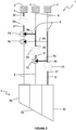
- the apparatus 1 of Figure 1 is shown in a second configuration in which the first three-way valve 7a has been adjusted to divert all of the pressurised water from the outlet 21 of the first pump 2a to the inlet 20 of the second pump 2b via the first diversion line 8a.
- the third three-way valve 7c has also been adjusted to divert all of the pressurised water from the outlet 21 of the second pump 2b to the inlet 20 of the third pump 2c via the third diversion line 8c.
- the non-return valves 9 prevent pressurised water from travelling back to the intakes 4.
- the pumps 2a, 2b, 2c are in a series arrangement such that the pressure of flow delivered from the outlet 21 of the first pump 2a is augmented by the second pump 2b and the flow delivered from the outlet 21 of the second pump 2b is augmented by the third pump 2c. Accordingly, the pressure of flow delivered from the outlet 21 of the third pump 2c is a combination of the pressure generated in all three pumps 2a, 2b, 2c.
- the water pressure supplied to, and subsequently evacuated from, the lower section 3c is therefore significantly higher than in the configuration shown in Figure 1 .
- the higher pressure water is useful to cut into adjacent substrates incorporating strong clays and hard soils, which might not otherwise be abraded by the lower water pressure delivered by the configuration of Figure 1 .
- the flow rate is reduced considerably and therefore a narrower area may be processed at any given time.
- the underwater trenching apparatus 10 includes only one uptake 4, which is fluidly connected to the first inlet 11a of a jet pump 11.
- the jet pump 11 also includes a second, intermediate inlet 11b and an outlet 11c.
- the second inlet 11b of the jet pump 11 is fluidly connected the outlet 21 of the first pump 2a via a regulating line 12.
- the output 11c of the jet pump 11 is fluidly connected to the feed lines 5 of each of the pumps 2a, 2b, 2c.
- the jet pump 11 provides a variable pressure boost to the water supplied to the inlets 20 of each of the pumps 2a, 2b, 2c, thereby significantly reducing the possibility of cavitation therein.
- a flow control valve 13 is also included in the regulating line 12 and is operably connected to the remotely located controller (not shown) via wired or wireless communication means.
- the flow restricting valve 13 may be operated to close fluid communication between the outlet 20 of the first pump 2a and the input 11b of the jet pump 11.
- the flow restricting valve 13 may be operated to open fluid communication between the outlet 21 of the first pump 2a and the input 11b of the jet pump 11 to bleed some of the higher pressure output flow from the first pump 2a into the jet pump 11 and hence prevent or reduce the incidence of cavitation.
- the configuration of the apparatus 10 shown in Figure 3 delivers pressurised water to each of the sections 3a, 3b, 3c, in a similar manner to the configuration of the underwater trenching apparatus 1 shown in Figure 1 .
- this arrangement is useful for cutting through adjacent substrates incorporating loose sands and weak clays.
- the apparatus 10 of Figure 3 is shown with a different configuration.
- the second three-way valve 7b has been adjusted to divert all of the pressurised water from the outlet 21 of the first pump 2a to the inlet 20 of the third pump 2c via the second diversion line 8b.
- the second pump 2b remains unchanged and supplies fluid flow to the middle section 3b of the jetting leg 3.
- the second non-return valve 7b prevents pressurised water from travelling back to the output 11c of the jet pump 11.
- the first and third pumps 2a, 2c are in a series arrangement, whereby the pressure of water pumped from the outlet 21 of the third pump 2c to the lower section 3c is a combination of pressures generated by the first and third pumps 2a, 2c.
- the second pump 2b behaves as before and pumps pressurised water to the middle section 3b at a similar pressure to the configuration shown in Figure 3 . Water is not pumped to the upper section 3a in the configuration of Figure 4 .
- the configuration of Figure 4 provides an increased water pressure output from the lower section 3c in comparison with the configuration of Figure 3 .
- This increased water pressure output from the lower section 3c is suitable for cutting into adjacent substrates incorporating intermediate clays and soils.
- the middle section 3b continues to provide a pressurised water output, albeit at a lower pressure. In this way the middle section 3b may cut through adjacent substrates incorporating soft clays and soils.
- this configuration increases the hardness of materials which may be cut by the apparatus 10 whilst maintaining, so far as possible, the rate with which trench cutting is achieved.
- the first embodiment of the underwater trenching apparatus 1 may have its three-way valves 7a, 7b, 7c configured in the manner described in relation to the alternative embodiment of the underwater trenching apparatus 10 shown in Figure 4 .
- the apparatus 1 according to the first embodiment may include one or more jet pumps 11 or other pressure boost means fluidly connected with one or more of the pumps 2a, 2b, 2c, with or without a check valve 13.
- the underwater trenching apparatus 1, 10 may include only two pumps 2a, 2b or more than three pumps 2a, 2b, 2c, for example four, five or six pumps.
- the underwater trenching apparatus 1, 10 includes a different number of pumps 2a, 2b, 2c to the embodiments described above, it will be appreciated that the quantity of respective sections 3a, 3b, 3c, three-way valves 7a, 7b, 7c, one-way valves 9, feed lines 5, diversion lines 8a, 8b, 8c and delivery lines 6 will be consequently altered in concert therewith.
- the apparatus need not include the jetting tool.
- the present invention also relates to a pumping apparatus.
- the pumping apparatus may be used with jetting tools having more or less sections than the number of pumps comprised in the pumping apparatus. In such instances, the skilled person would appreciate the various connection arrangements possible.
- the supply of pressurised water to one or more of the sections 3a, 3b, 3c of the jet cutting leg 3 may be further adjustably controlled by use of one or more constriction valves, for example where such constriction valves are included in the delivery lines 6.
- the constriction valves may be operatively connected to a remotely located controller which may adjust the constriction of the constriction valves in order to selectively reduce or increase the flow of pressurised water to one or more of the sections 3a, 3b, 3c. In this way the pressure and flow rate of pressurised water delivered by one or more of the pumps 2a, 2b, 2c may be selectively controlled.
- the three-way valves 7a, 7b, 7c have been described above as being adjusted to divert or allow passage therethrough of all of the pressurised water this need not be the case.
- One or more of the three-way valves 7a, 7b, 7c may be adjusted in a step-wise or continuous manner such that a first portion of pressurised water delivered by one or more of the three-way valves 7a, 7b, 7c is passed therethrough and a second portion of the pressurised water is diverted to a diversion line 8a, 8b, 8c.
- the three-way valves 7a, 7b, 7c may be manually adjustable.
- the apparatus 1 may include less than three uptakes 4, for example only one uptake 4 as described in relation to the alternative embodiment of the underwater trenching apparatus 10 shown in Figure 3 .
- the jet cutting leg 3 of the underwater trenching apparatus 1, 10 may be removable and may be replaced, prior to use, by one or more alternative jet cutting legs 3, for example jet cutting legs 3 including more or less than three sections 3a, 3b, 3c.
- an alternative jet cutting leg 3 may include only two sections 3a, 3b, an upper and a lower section 3a, 3b, and may have a shorter height than the jet cutting leg 3 described in the embodiment of Figure 1 .
- the underwater trenching apparatus 1, 10 is provided with a jet cutting leg 3 having only two sections 3a, 3b one of the pumps 2a, 2b, 2c may be selectively prevented from pumping pressurised water towards the jet cutting leg, for example by a valve.
- an underwater trenching apparatus 1, 10 includes more pumps 2a, 2b, 2c than sections 3a, 3b, 3c one or more of the three-way valves 7a, 7b, 7c may be adjusted to divert pressurised water from the output 21 of one or more pumps 2a, 2b, 2c towards the input 20 of a further pump 2a, 2b, 2c.
- the quantity of pumps 2a, 2b, 2c which deliver pressurised water to sections 3a, 3b, 3c may be matched with the quantity of available sections 3a, 3b, 3c.
Landscapes
- Engineering & Computer Science (AREA)
- Mechanical Engineering (AREA)
- General Engineering & Computer Science (AREA)
- Mining & Mineral Resources (AREA)
- Civil Engineering (AREA)
- Structural Engineering (AREA)
- Computer Hardware Design (AREA)
- Physics & Mathematics (AREA)
- Fluid Mechanics (AREA)
- Perforating, Stamping-Out Or Severing By Means Other Than Cutting (AREA)
- Earth Drilling (AREA)
- Control Of Positive-Displacement Pumps (AREA)
- Details Of Reciprocating Pumps (AREA)
- Jet Pumps And Other Pumps (AREA)
Claims (15)
- Appareil de pompage utilisé dans un appareil d'excavation sous-marine, comprenant une première pompe (2a) possédant une admission (20) pour le raccordement fluidique avec une source de liquide, et une évacuation (21) pour le raccordement fluidique avec la première section (3a) d'un outil d'injection (3), caractérisé en ce que l'appareil comprend en outre une deuxième pompe (2b, 2c) possédant une admission (20) pour le raccordement fluidique avec une source de liquide, et une évacuation (21) pour le raccordement fluidique avec la deuxième section (3b, 3c) d'un outil d'injection (3), l'évacuation de la première pompe étant raccordée à l'admission de la deuxième pompe par un dispositif à vannes (7a, 7b) pouvant être actionné pour dévier au moins une partie d'un débit d'évacuation de la première pompe de la première section de l'outil d'injection à l'admission de la deuxième pompe.
- Appareil selon la revendication 1, comprenant une troisième pompe (2c) possédant une admission (20) pour le raccordement fluidique avec une source de liquide, et une évacuation (21) raccordée par le fluide pour le raccordement fluidique avec une troisième section (3c) d'un outil d'injection (3), l'évacuation de la deuxième pompe (2b) étant raccordée par le fluide à l'admission de la troisième pompe par le, ou un autre, dispositif à vannes (7c) de l'appareil, pouvant être actionné pour dévier au moins une partie d'un débit d'évacuation de la deuxième pompe à l'admission de la troisième pompe.
- Appareil selon une quelconque des revendications précédentes, le ou chaque dispositif à vannes (7a, 7b, 7c) pouvant être ajusté, en cours d'usage, pour modifier ou varier la proportion du débit d'évacuation qui est dévié ; et/ou
le ou chaque dispositif à vannes (7a, 7b, 7c) comprenant un robinet mélangeur. - Appareil selon une quelconque des revendications 1 à 2, le ou chaque dispositif à vannes (7a, 7b, 7c) pouvant être actionné pour fermer, en cours d'usage, le raccordement fluidique entre l'évacuation de la pompe et la section appropriée de l'outil d'injection avant, ou au moment de, l'ouverture d'un raccordement fluidique entre l'évacuation de la pompe et l'admission de l'autre pompe.
- Appareil selon une quelconque des revendications 1 à 2, le ou chaque dispositif à vannes (7a, 7b, 7c) comprenant un dispositif à vannes à flux dirigé ou à boisseau.
- Appareil selon une quelconque des revendications précédentes, comprenant un dispositif de régulation raccordé à la ou chaque pompe, et configuré pour en assurer la régulation ; et
le ou chaque dispositif à vannes (7a, 7b, 7c) comprenant, en option, une vanne munie d'un actionneur connecté fonctionnellement au dispositif de régulation et pouvant être commandé automatiquement par celui-ci. - Appareil selon une quelconque des revendications précédentes, comprenant un clapet de retenue (9) doté d'une entrée pour le raccordement fluidique avec la source et une sortie raccordée par le fluide à l'admission (20) de la deuxième pompe (2b, 2c), le clapet de retenue étant configuré pour permettre un débit de fluide de la source à l'admission de la deuxième pompe, et empêcher un débit de fluide à la source ou vers celle-ci.
- Appareil selon la revendication 7, lorsqu'elle est tributaire de la revendication 2, comprenant un autre clapet de retenue (9) doté d'une admission pour le raccordement fluidique avec la source et une évacuation raccordée par le fluide à l'admission de la troisième pompe (2c), l'autre clapet de retenue étant configuré pour permettre un débit de fluide de la source à l'admission de la troisième pompe, et empêcher un débit de fluide à la source ou vers celle-ci.
- Appareil selon une quelconque des revendications précédentes, comprenant un dispositif de surpression connecté à l'admission de chacune des première et deuxième pompes, et pouvant être utilisé, lorsque la pression ambiante est substantiellement insuffisante pour empêcher une cavitation dans la première ou la deuxième pompe, pour augmenter localement la pression à l'admission de celle-ci ; et, en option, le dispositif de surpression comprenant une ou plusieurs pompes à injection (11).
- Appareil selon une quelconque des revendications précédentes, la connexion entre la ou chaque source et la ou chaque pompe ou clapet de retenue comprenant un filtre d'admission.
- Appareil d'excavation sous-marine comprenant :un appareil de pompage selon une quelconque des revendications 1 à 10 ; etun outil d'injection (3) pour le creusement de tranchées avec une première (3a) et une deuxième (3b, 3c) sections ;l'évacuation de la première pompe étant raccordée par le fluide à la première section de l'outil d'injection, l'évacuation de la deuxième pompe étant raccordée par le fluide à la deuxième section de l'outil d'injection.
- Méthode d'utilisation d'un appareil d'excavation sous-marine, caractérisée en ce que la méthode comprend la diversion d'au moins une partie du débit d'évacuation d'une première pompe (2a) de la première section (3a) d'un outil d'injection (3) à l'admission (20) d'une deuxième pompe (2b, 2c) raccordée par le fluide à une deuxième section (3b, 3c) de l'outil d'injection (3) de façon à augmenter la pression du débit d'évacuation de la deuxième pompe fournie à la deuxième section de l'outil d'injection.
- Méthode selon la revendication 12, comprenant en outre la diversion d'au moins une partie du débit d'évacuation de la deuxième pompe (2b) de la deuxième section (3b) de l'outil d'injection (3) à l'admission (20) d'une troisième pompe (2c) raccordée par le fluide à une troisième section (3c) de l'outil d'injection (3) de façon à augmenter la pression du débit d'évacuation de la troisième pompe fourni à la troisième section de l'outil d'injection.
- Méthode selon la revendication 12 ou la revendication 13, comprenant la diversion d'une partie seulement du débit d'évacuation de la première pompe (2a), de sorte qu'une partie du débit d'évacuation soit fournie à la première section (3a) de l'outil d'injection (3) et une autre partie du débit d'évacuation soit fournie à l'admission (20) de la deuxième pompe (2b, 2c).
- Méthode selon une quelconque des revendications 12 à 14, comprenant la variation de la proportion du débit d'évacuation qui est dévié en réponse à une commande reçue par un utilisateur et/ou conformément à différentes spécifications ; et/ou
la méthode comprenant la diversion de la partie du débit d'évacuation d'une ou plusieurs des pompes en utilisant un dispositif de régulation ; et/ou
la méthode comprenant l'augmentation localement de la pression d'un débit de fluide à l'admission de la première et/ou la deuxième pompe pour empêcher toute cavitation de ou dans celle-ci.
Applications Claiming Priority (2)
| Application Number | Priority Date | Filing Date | Title |
|---|---|---|---|
| GBGB1513484.4A GB201513484D0 (en) | 2015-07-30 | 2015-07-30 | Underwater trenching apparatus and pumping apparatus |
| PCT/GB2016/052277 WO2017017431A1 (fr) | 2015-07-30 | 2016-07-25 | Appareil sous-marin de creusement de tranchées et de pompage |
Publications (2)
| Publication Number | Publication Date |
|---|---|
| EP3329054A1 EP3329054A1 (fr) | 2018-06-06 |
| EP3329054B1 true EP3329054B1 (fr) | 2020-02-19 |
Family
ID=54062935
Family Applications (1)
| Application Number | Title | Priority Date | Filing Date |
|---|---|---|---|
| EP16744506.3A Active EP3329054B1 (fr) | 2015-07-30 | 2016-07-25 | Appareil sous-marin de creusement de tranchées et de pompage |
Country Status (6)
| Country | Link |
|---|---|
| US (1) | US10895060B2 (fr) |
| EP (1) | EP3329054B1 (fr) |
| JP (1) | JP6799062B2 (fr) |
| CN (1) | CN108026711B (fr) |
| GB (1) | GB201513484D0 (fr) |
| WO (1) | WO2017017431A1 (fr) |
Families Citing this family (1)
| Publication number | Priority date | Publication date | Assignee | Title |
|---|---|---|---|---|
| NL2034472B1 (en) * | 2023-03-30 | 2024-10-04 | Royal Ihc Ltd | Trench cutter |
Family Cites Families (15)
| Publication number | Priority date | Publication date | Assignee | Title |
|---|---|---|---|---|
| US2112651A (en) * | 1935-09-19 | 1938-03-29 | Ahrens Fox Fire Engine Company | Centrifugal pump |
| US2669941A (en) * | 1949-12-15 | 1954-02-23 | John W Stafford | Continuous liquid pumping system |
| US3005417A (en) * | 1957-04-26 | 1961-10-24 | United States Steel Corp | Pneumatic system for pumping liquid |
| GB1102967A (en) * | 1965-01-18 | 1968-02-14 | Itzhak Lustig | Improvements in pump systems |
| US3552884A (en) * | 1967-07-20 | 1971-01-05 | Giovanni Faldi | Fluid pumping station working on the compressed air principle with partial recovery and re-cycling of the air |
| US4253255A (en) * | 1979-01-08 | 1981-03-03 | Durell William E | Automated dredging with vacuum assist |
| JPS5677586A (en) * | 1979-11-29 | 1981-06-25 | Kawamoto Seisakusho:Kk | Controlling method for pump |
| US4353174A (en) * | 1980-08-11 | 1982-10-12 | Amtec Development Company | Electronic control system for pneumatic-hydraulic pump dredge |
| SE501194C2 (sv) * | 1993-04-27 | 1994-12-05 | Flygt Ab Itt | Anordning för att minska risken för igensättning av pumpar för avloppsvatten och andra vätskor innehållande fasta föroreningar |
| AU4724297A (en) * | 1996-11-02 | 1998-05-29 | Moburon Design Office Co., Ltd. | Dredging method and dredging apparatus |
| JP2000013947A (ja) * | 1998-06-17 | 2000-01-14 | Fujikura Ltd | 埋設機装置 |
| NO311639B1 (no) * | 2000-04-05 | 2001-12-27 | Gto Subsea As | Fremgangsmåte og anordning for å flytte på stein og lösmasser under vann |
| GB2363407A (en) * | 2000-06-12 | 2001-12-19 | Frank Mohn Flatoey As | Trenching apparatus |
| US6705029B2 (en) * | 2002-03-21 | 2004-03-16 | Richard A. Anderson | Trenching machine |
| GB201122117D0 (en) * | 2011-12-22 | 2012-02-01 | Ihc Engineering Business Ltd | Pump apparatus |
-
2015
- 2015-07-30 GB GBGB1513484.4A patent/GB201513484D0/en not_active Ceased
-
2016
- 2016-07-25 CN CN201680044871.0A patent/CN108026711B/zh not_active Expired - Fee Related
- 2016-07-25 US US15/747,337 patent/US10895060B2/en active Active
- 2016-07-25 EP EP16744506.3A patent/EP3329054B1/fr active Active
- 2016-07-25 JP JP2018524564A patent/JP6799062B2/ja active Active
- 2016-07-25 WO PCT/GB2016/052277 patent/WO2017017431A1/fr not_active Ceased
Non-Patent Citations (1)
| Title |
|---|
| None * |
Also Published As
| Publication number | Publication date |
|---|---|
| CN108026711B (zh) | 2021-05-14 |
| CN108026711A (zh) | 2018-05-11 |
| JP2018523771A (ja) | 2018-08-23 |
| JP6799062B2 (ja) | 2020-12-09 |
| EP3329054A1 (fr) | 2018-06-06 |
| US10895060B2 (en) | 2021-01-19 |
| GB201513484D0 (en) | 2015-09-16 |
| US20180216312A1 (en) | 2018-08-02 |
| WO2017017431A1 (fr) | 2017-02-02 |
Similar Documents
| Publication | Publication Date | Title |
|---|---|---|
| RU2598953C2 (ru) | Насосная система | |
| EP3339516A3 (fr) | Appareil et procédé de commande d'un véhicule de travail | |
| MX2019006134A (es) | Una planta para controlar el suministro de fluido presurizado en un conducto, y un metodo para controlar un motor principal. | |
| US9377065B2 (en) | Transmission hydraulic retarder control system and method of operating | |
| EP3255284B1 (fr) | Vanne de commande d'écoulement pour machine de construction | |
| CN102774483A (zh) | 一种多功能潜水器水液压系统 | |
| US7264059B2 (en) | Method and device for pressure controlled sequential operation | |
| RU2698149C2 (ru) | Гидравлическая система машины и машина | |
| RU2700971C2 (ru) | Гидравлическая система, способ управления и машина, содержащая данную гидравлическую систему | |
| EP3329054B1 (fr) | Appareil sous-marin de creusement de tranchées et de pompage | |
| ZA200609464B (en) | Controlled dispersion multi-phase nozzle and method of making the same | |
| US9133690B1 (en) | System and method for mitigating pressure drop at subsea pump startup | |
| EP1764515A2 (fr) | Système hydraulique pour engins de construction | |
| CN103321978A (zh) | 液压辅助阀装置和带有该液压辅助阀装置的液压阀装置 | |
| CA2648927A1 (fr) | Circuit de fluide avec ecoulements multiples provenant de soupapes en serie | |
| US9719232B2 (en) | Pump apparatus and underwater trenching apparatus | |
| CN109469657B (zh) | 液压系统和钻井机 | |
| EP1797326A2 (fr) | Systeme et procede de distribution de fluide sous-marin | |
| JP2014156891A5 (fr) | ||
| CN204692224U (zh) | 一种合流控制阀 | |
| EP3093401B1 (fr) | Appareil pour commander une opération combinée d'un engin de chantier | |
| EP2339073A1 (fr) | Système hydraulique pour machine, machine et procédé d'utilisation | |
| EP3255285B1 (fr) | Procédé de commande d'entraînement d'actionneur hydraulique d'engin de chantier | |
| WO2010112779A3 (fr) | Dispositif d'intervention dans un puits d'exploitation de fluide, installation d'exploitation et procédé associé | |
| CN108278107A (zh) | 钻机用的控制系统以及钻机 |
Legal Events
| Date | Code | Title | Description |
|---|---|---|---|
| STAA | Information on the status of an ep patent application or granted ep patent |
Free format text: STATUS: THE INTERNATIONAL PUBLICATION HAS BEEN MADE |
|
| PUAI | Public reference made under article 153(3) epc to a published international application that has entered the european phase |
Free format text: ORIGINAL CODE: 0009012 |
|
| STAA | Information on the status of an ep patent application or granted ep patent |
Free format text: STATUS: REQUEST FOR EXAMINATION WAS MADE |
|
| 17P | Request for examination filed |
Effective date: 20180117 |
|
| AK | Designated contracting states |
Kind code of ref document: A1 Designated state(s): AL AT BE BG CH CY CZ DE DK EE ES FI FR GB GR HR HU IE IS IT LI LT LU LV MC MK MT NL NO PL PT RO RS SE SI SK SM TR |
|
| AX | Request for extension of the european patent |
Extension state: BA ME |
|
| DAV | Request for validation of the european patent (deleted) | ||
| DAX | Request for extension of the european patent (deleted) | ||
| GRAP | Despatch of communication of intention to grant a patent |
Free format text: ORIGINAL CODE: EPIDOSNIGR1 |
|
| STAA | Information on the status of an ep patent application or granted ep patent |
Free format text: STATUS: GRANT OF PATENT IS INTENDED |
|
| INTG | Intention to grant announced |
Effective date: 20190927 |
|
| RAP1 | Party data changed (applicant data changed or rights of an application transferred) |
Owner name: IHC ENGINEERING BUSINESS LIMITED |
|
| RAP1 | Party data changed (applicant data changed or rights of an application transferred) |
Owner name: ROYAL IHC LIMITED |
|
| GRAS | Grant fee paid |
Free format text: ORIGINAL CODE: EPIDOSNIGR3 |
|
| GRAA | (expected) grant |
Free format text: ORIGINAL CODE: 0009210 |
|
| STAA | Information on the status of an ep patent application or granted ep patent |
Free format text: STATUS: THE PATENT HAS BEEN GRANTED |
|
| AK | Designated contracting states |
Kind code of ref document: B1 Designated state(s): AL AT BE BG CH CY CZ DE DK EE ES FI FR GB GR HR HU IE IS IT LI LT LU LV MC MK MT NL NO PL PT RO RS SE SI SK SM TR |
|
| REG | Reference to a national code |
Ref country code: CH Ref legal event code: EP |
|
| REG | Reference to a national code |
Ref country code: DE Ref legal event code: R096 Ref document number: 602016030101 Country of ref document: DE |
|
| REG | Reference to a national code |
Ref country code: AT Ref legal event code: REF Ref document number: 1235106 Country of ref document: AT Kind code of ref document: T Effective date: 20200315 |
|
| REG | Reference to a national code |
Ref country code: IE Ref legal event code: FG4D |
|
| REG | Reference to a national code |
Ref country code: NL Ref legal event code: FP |
|
| REG | Reference to a national code |
Ref country code: NO Ref legal event code: T2 Effective date: 20200219 |
|
| PG25 | Lapsed in a contracting state [announced via postgrant information from national office to epo] |
Ref country code: FI Free format text: LAPSE BECAUSE OF FAILURE TO SUBMIT A TRANSLATION OF THE DESCRIPTION OR TO PAY THE FEE WITHIN THE PRESCRIBED TIME-LIMIT Effective date: 20200219 Ref country code: RS Free format text: LAPSE BECAUSE OF FAILURE TO SUBMIT A TRANSLATION OF THE DESCRIPTION OR TO PAY THE FEE WITHIN THE PRESCRIBED TIME-LIMIT Effective date: 20200219 |
|
| REG | Reference to a national code |
Ref country code: LT Ref legal event code: MG4D |
|
| PG25 | Lapsed in a contracting state [announced via postgrant information from national office to epo] |
Ref country code: HR Free format text: LAPSE BECAUSE OF FAILURE TO SUBMIT A TRANSLATION OF THE DESCRIPTION OR TO PAY THE FEE WITHIN THE PRESCRIBED TIME-LIMIT Effective date: 20200219 Ref country code: GR Free format text: LAPSE BECAUSE OF FAILURE TO SUBMIT A TRANSLATION OF THE DESCRIPTION OR TO PAY THE FEE WITHIN THE PRESCRIBED TIME-LIMIT Effective date: 20200520 Ref country code: LV Free format text: LAPSE BECAUSE OF FAILURE TO SUBMIT A TRANSLATION OF THE DESCRIPTION OR TO PAY THE FEE WITHIN THE PRESCRIBED TIME-LIMIT Effective date: 20200219 Ref country code: IS Free format text: LAPSE BECAUSE OF FAILURE TO SUBMIT A TRANSLATION OF THE DESCRIPTION OR TO PAY THE FEE WITHIN THE PRESCRIBED TIME-LIMIT Effective date: 20200619 Ref country code: SE Free format text: LAPSE BECAUSE OF FAILURE TO SUBMIT A TRANSLATION OF THE DESCRIPTION OR TO PAY THE FEE WITHIN THE PRESCRIBED TIME-LIMIT Effective date: 20200219 Ref country code: BG Free format text: LAPSE BECAUSE OF FAILURE TO SUBMIT A TRANSLATION OF THE DESCRIPTION OR TO PAY THE FEE WITHIN THE PRESCRIBED TIME-LIMIT Effective date: 20200519 |
|
| PG25 | Lapsed in a contracting state [announced via postgrant information from national office to epo] |
Ref country code: ES Free format text: LAPSE BECAUSE OF FAILURE TO SUBMIT A TRANSLATION OF THE DESCRIPTION OR TO PAY THE FEE WITHIN THE PRESCRIBED TIME-LIMIT Effective date: 20200219 Ref country code: RO Free format text: LAPSE BECAUSE OF FAILURE TO SUBMIT A TRANSLATION OF THE DESCRIPTION OR TO PAY THE FEE WITHIN THE PRESCRIBED TIME-LIMIT Effective date: 20200219 Ref country code: CZ Free format text: LAPSE BECAUSE OF FAILURE TO SUBMIT A TRANSLATION OF THE DESCRIPTION OR TO PAY THE FEE WITHIN THE PRESCRIBED TIME-LIMIT Effective date: 20200219 Ref country code: SM Free format text: LAPSE BECAUSE OF FAILURE TO SUBMIT A TRANSLATION OF THE DESCRIPTION OR TO PAY THE FEE WITHIN THE PRESCRIBED TIME-LIMIT Effective date: 20200219 Ref country code: LT Free format text: LAPSE BECAUSE OF FAILURE TO SUBMIT A TRANSLATION OF THE DESCRIPTION OR TO PAY THE FEE WITHIN THE PRESCRIBED TIME-LIMIT Effective date: 20200219 Ref country code: EE Free format text: LAPSE BECAUSE OF FAILURE TO SUBMIT A TRANSLATION OF THE DESCRIPTION OR TO PAY THE FEE WITHIN THE PRESCRIBED TIME-LIMIT Effective date: 20200219 Ref country code: DK Free format text: LAPSE BECAUSE OF FAILURE TO SUBMIT A TRANSLATION OF THE DESCRIPTION OR TO PAY THE FEE WITHIN THE PRESCRIBED TIME-LIMIT Effective date: 20200219 Ref country code: PT Free format text: LAPSE BECAUSE OF FAILURE TO SUBMIT A TRANSLATION OF THE DESCRIPTION OR TO PAY THE FEE WITHIN THE PRESCRIBED TIME-LIMIT Effective date: 20200712 Ref country code: SK Free format text: LAPSE BECAUSE OF FAILURE TO SUBMIT A TRANSLATION OF THE DESCRIPTION OR TO PAY THE FEE WITHIN THE PRESCRIBED TIME-LIMIT Effective date: 20200219 |
|
| PGFP | Annual fee paid to national office [announced via postgrant information from national office to epo] |
Ref country code: DE Payment date: 20200717 Year of fee payment: 5 |
|
| REG | Reference to a national code |
Ref country code: AT Ref legal event code: MK05 Ref document number: 1235106 Country of ref document: AT Kind code of ref document: T Effective date: 20200219 |
|
| REG | Reference to a national code |
Ref country code: DE Ref legal event code: R097 Ref document number: 602016030101 Country of ref document: DE |
|
| PLBE | No opposition filed within time limit |
Free format text: ORIGINAL CODE: 0009261 |
|
| STAA | Information on the status of an ep patent application or granted ep patent |
Free format text: STATUS: NO OPPOSITION FILED WITHIN TIME LIMIT |
|
| 26N | No opposition filed |
Effective date: 20201120 |
|
| PG25 | Lapsed in a contracting state [announced via postgrant information from national office to epo] |
Ref country code: AT Free format text: LAPSE BECAUSE OF FAILURE TO SUBMIT A TRANSLATION OF THE DESCRIPTION OR TO PAY THE FEE WITHIN THE PRESCRIBED TIME-LIMIT Effective date: 20200219 |
|
| PG25 | Lapsed in a contracting state [announced via postgrant information from national office to epo] |
Ref country code: PL Free format text: LAPSE BECAUSE OF FAILURE TO SUBMIT A TRANSLATION OF THE DESCRIPTION OR TO PAY THE FEE WITHIN THE PRESCRIBED TIME-LIMIT Effective date: 20200219 Ref country code: MC Free format text: LAPSE BECAUSE OF FAILURE TO SUBMIT A TRANSLATION OF THE DESCRIPTION OR TO PAY THE FEE WITHIN THE PRESCRIBED TIME-LIMIT Effective date: 20200219 Ref country code: SI Free format text: LAPSE BECAUSE OF FAILURE TO SUBMIT A TRANSLATION OF THE DESCRIPTION OR TO PAY THE FEE WITHIN THE PRESCRIBED TIME-LIMIT Effective date: 20200219 |
|
| REG | Reference to a national code |
Ref country code: CH Ref legal event code: PL |
|
| PG25 | Lapsed in a contracting state [announced via postgrant information from national office to epo] |
Ref country code: CH Free format text: LAPSE BECAUSE OF NON-PAYMENT OF DUE FEES Effective date: 20200731 Ref country code: LU Free format text: LAPSE BECAUSE OF NON-PAYMENT OF DUE FEES Effective date: 20200725 Ref country code: LI Free format text: LAPSE BECAUSE OF NON-PAYMENT OF DUE FEES Effective date: 20200731 |
|
| PG25 | Lapsed in a contracting state [announced via postgrant information from national office to epo] |
Ref country code: IE Free format text: LAPSE BECAUSE OF NON-PAYMENT OF DUE FEES Effective date: 20200725 |
|
| REG | Reference to a national code |
Ref country code: DE Ref legal event code: R119 Ref document number: 602016030101 Country of ref document: DE |
|
| PG25 | Lapsed in a contracting state [announced via postgrant information from national office to epo] |
Ref country code: DE Free format text: LAPSE BECAUSE OF NON-PAYMENT OF DUE FEES Effective date: 20220201 |
|
| PG25 | Lapsed in a contracting state [announced via postgrant information from national office to epo] |
Ref country code: TR Free format text: LAPSE BECAUSE OF FAILURE TO SUBMIT A TRANSLATION OF THE DESCRIPTION OR TO PAY THE FEE WITHIN THE PRESCRIBED TIME-LIMIT Effective date: 20200219 Ref country code: MT Free format text: LAPSE BECAUSE OF FAILURE TO SUBMIT A TRANSLATION OF THE DESCRIPTION OR TO PAY THE FEE WITHIN THE PRESCRIBED TIME-LIMIT Effective date: 20200219 Ref country code: CY Free format text: LAPSE BECAUSE OF FAILURE TO SUBMIT A TRANSLATION OF THE DESCRIPTION OR TO PAY THE FEE WITHIN THE PRESCRIBED TIME-LIMIT Effective date: 20200219 |
|
| PG25 | Lapsed in a contracting state [announced via postgrant information from national office to epo] |
Ref country code: MK Free format text: LAPSE BECAUSE OF FAILURE TO SUBMIT A TRANSLATION OF THE DESCRIPTION OR TO PAY THE FEE WITHIN THE PRESCRIBED TIME-LIMIT Effective date: 20200219 Ref country code: AL Free format text: LAPSE BECAUSE OF FAILURE TO SUBMIT A TRANSLATION OF THE DESCRIPTION OR TO PAY THE FEE WITHIN THE PRESCRIBED TIME-LIMIT Effective date: 20200219 |
|
| P01 | Opt-out of the competence of the unified patent court (upc) registered |
Effective date: 20230522 |
|
| REG | Reference to a national code |
Ref country code: GB Ref legal event code: 732E Free format text: REGISTERED BETWEEN 20231214 AND 20231220 |
|
| PGFP | Annual fee paid to national office [announced via postgrant information from national office to epo] |
Ref country code: NL Payment date: 20250716 Year of fee payment: 10 |
|
| PGFP | Annual fee paid to national office [announced via postgrant information from national office to epo] |
Ref country code: NO Payment date: 20250718 Year of fee payment: 10 |
|
| PGFP | Annual fee paid to national office [announced via postgrant information from national office to epo] |
Ref country code: IT Payment date: 20250714 Year of fee payment: 10 |
|
| PGFP | Annual fee paid to national office [announced via postgrant information from national office to epo] |
Ref country code: GB Payment date: 20250701 Year of fee payment: 10 Ref country code: BE Payment date: 20250716 Year of fee payment: 10 |
|
| PGFP | Annual fee paid to national office [announced via postgrant information from national office to epo] |
Ref country code: FR Payment date: 20250721 Year of fee payment: 10 |