EP3330475B2 - Schiene für eine architektonische öffnungsabdeckung - Google Patents
Schiene für eine architektonische öffnungsabdeckung Download PDFInfo
- Publication number
- EP3330475B2 EP3330475B2 EP17204739.1A EP17204739A EP3330475B2 EP 3330475 B2 EP3330475 B2 EP 3330475B2 EP 17204739 A EP17204739 A EP 17204739A EP 3330475 B2 EP3330475 B2 EP 3330475B2
- Authority
- EP
- European Patent Office
- Prior art keywords
- rail
- cord
- base
- support
- retention member
- Prior art date
- Legal status (The legal status is an assumption and is not a legal conclusion. Google has not performed a legal analysis and makes no representation as to the accuracy of the status listed.)
- Active
Links
Images




Classifications
-
- E—FIXED CONSTRUCTIONS
- E06—DOORS, WINDOWS, SHUTTERS, OR ROLLER BLINDS IN GENERAL; LADDERS
- E06B—FIXED OR MOVABLE CLOSURES FOR OPENINGS IN BUILDINGS, VEHICLES, FENCES OR LIKE ENCLOSURES IN GENERAL, e.g. DOORS, WINDOWS, BLINDS, GATES
- E06B9/00—Screening or protective devices for wall or similar openings, with or without operating or securing mechanisms; Closures of similar construction
- E06B9/24—Screens or other constructions affording protection against light, especially against sunshine; Similar screens for privacy or appearance; Slat blinds
- E06B9/26—Lamellar or like blinds, e.g. venetian blinds
- E06B9/28—Lamellar or like blinds, e.g. venetian blinds with horizontal lamellae, e.g. non-liftable
- E06B9/30—Lamellar or like blinds, e.g. venetian blinds with horizontal lamellae, e.g. non-liftable liftable
- E06B9/32—Operating, guiding, or securing devices therefor
- E06B9/327—Guides for raisable lamellar blinds with horizontal lamellae
-
- E—FIXED CONSTRUCTIONS
- E06—DOORS, WINDOWS, SHUTTERS, OR ROLLER BLINDS IN GENERAL; LADDERS
- E06B—FIXED OR MOVABLE CLOSURES FOR OPENINGS IN BUILDINGS, VEHICLES, FENCES OR LIKE ENCLOSURES IN GENERAL, e.g. DOORS, WINDOWS, BLINDS, GATES
- E06B9/00—Screening or protective devices for wall or similar openings, with or without operating or securing mechanisms; Closures of similar construction
- E06B9/24—Screens or other constructions affording protection against light, especially against sunshine; Similar screens for privacy or appearance; Slat blinds
- E06B9/26—Lamellar or like blinds, e.g. venetian blinds
- E06B9/38—Other details
- E06B9/388—Details of bottom or upper slats or their attachment
-
- E—FIXED CONSTRUCTIONS
- E06—DOORS, WINDOWS, SHUTTERS, OR ROLLER BLINDS IN GENERAL; LADDERS
- E06B—FIXED OR MOVABLE CLOSURES FOR OPENINGS IN BUILDINGS, VEHICLES, FENCES OR LIKE ENCLOSURES IN GENERAL, e.g. DOORS, WINDOWS, BLINDS, GATES
- E06B9/00—Screening or protective devices for wall or similar openings, with or without operating or securing mechanisms; Closures of similar construction
- E06B9/24—Screens or other constructions affording protection against light, especially against sunshine; Similar screens for privacy or appearance; Slat blinds
- E06B9/40—Roller blinds
- E06B9/42—Parts or details of roller blinds, e.g. suspension devices, blind boxes
-
- E—FIXED CONSTRUCTIONS
- E06—DOORS, WINDOWS, SHUTTERS, OR ROLLER BLINDS IN GENERAL; LADDERS
- E06B—FIXED OR MOVABLE CLOSURES FOR OPENINGS IN BUILDINGS, VEHICLES, FENCES OR LIKE ENCLOSURES IN GENERAL, e.g. DOORS, WINDOWS, BLINDS, GATES
- E06B9/00—Screening or protective devices for wall or similar openings, with or without operating or securing mechanisms; Closures of similar construction
- E06B9/24—Screens or other constructions affording protection against light, especially against sunshine; Similar screens for privacy or appearance; Slat blinds
- E06B9/26—Lamellar or like blinds, e.g. venetian blinds
- E06B9/28—Lamellar or like blinds, e.g. venetian blinds with horizontal lamellae, e.g. non-liftable
- E06B9/30—Lamellar or like blinds, e.g. venetian blinds with horizontal lamellae, e.g. non-liftable liftable
- E06B9/32—Operating, guiding, or securing devices therefor
- E06B9/322—Details of operating devices, e.g. pulleys, brakes, spring drums, drives
- E06B2009/3222—Cordless, i.e. user interface without cords
Definitions
- the following relates to a rail for use as a movable rail in an architectural structure covering, in particular including a cord guiding insert for mounting at an end of the rail.
- an architectural covering having a shade which is extendable over or retractable from the architectural structure.
- the shade may extend from a fixed portion at one side of the structure to a movable rail or it may be extendable between two respective movable rails, each movable with respect to the structure.
- cords may be provided which extend through the movable rail and along the edges of the structure along which the movable rail moves.
- magnetic plates may be provided at the side of the structure to which the movable rail may be moved so as to ensure that the movable rail fully closes against that side.
- US 2005/092446 A describes a cordless Venetian blind structure including a lower beam having a pair of clamps securely sealed at both ends thereof for a left and a right retaining cords to be held thereby before pivotally led through the bottom of the lower beam to be tied up to a windowsill for location thereon.
- a retaining unit and a control unit are mounted to the middle section of the lower beam respectively with the control unit limited by the retaining unit in pushing operation.
- a control cord pivotally led through the retaining unit and the control unit respectively at the middle section is attached to the clamps by both ends thereof.
- control unit In operation, the control unit is pushed inwards to draw in the control cord by both ends and compress spring elements disposed at the clamps therein so as to release the retaining cords from the clamps for adjusting the Venetian blind up or down into a proper position.
- the clamps When the pushing force applied is removed, the clamps are bounced back, clamping tight the retaining cords thereof so as to relocate the Venetian blind at the proper position under the best using condition thereof.
- a pair of coupling bodies can also be attached at both ends of the lower beam thereof with the same effect thereof.
- DE 20 2015 105004 D1 describes a rotatable assembly system for attachment to a head rail of a blind without drawstring and turning bar, wherein the rotatable assembly system comprises: an inner member having an inner side in the direction of the head rail, an outer side which faces the inner side of the inner member, an engagement segment formed on the inner side of the inner member and with which an end of the head rail is engaged, a cable opening formed by the inner member and a positioning recess formed in the outer side of the inner member, an outer member mounted on the inner member and an inner side disposed toward the head rail, an outer side; facing the inside of the outer member and including a circular hole formed through the outer member, a stationary member rotatably disposed between the inner member and the outer member, and a circular plate portion having a free end disposed between the inner member and the outer member, a first hole passing through the first hole circular plate portion and communicating with the cable opening of the inner member and a plurality of hemispherical recesses formed in the free end of the circular plate portion
- the cord or cords may already be provided along the rail before fitment of the cord guiding insert. Because insertion of the cord guiding insert into the end of the rail forms, with the inner profile shape of the rail, the cord opening, the cord guiding insert may be inserted into the first end of the rail with the cord or cords already in place in the rail. Furthermore, because the cord guiding insert itself does not require holes therethrough, moulding of the cord guiding insert is simplified.
- the at least one insert portion may extend substantially perpendicular to the inner surface. Also, the inner surface and the outer surface may be substantially parallel. Such an arrangement will be useful for the rails having ends substantially perpendicular to the elongate extent of the rails.
- the outer surface of the base may define an additional channel extending from the first side to the second side for guiding an additional cord respectively.
- an additional cord may be provided in the rail.
- the cords may be kept from interfering from one another.
- the base may include a wall between and defining the channel and the additional channel.
- multiple walls may be provided where more channels are provided.
- the wall may extend beyond the first side at least partly across the cord opening so as to define the respective cord paths through the cord opening.
- the extending wall or walls may assist in separating the cords and preventing interference between one another.
- the wall or walls may extend across the opening to meet with the inner profile shape. In this way, the wall or walls will form completely separate respective cord openings.
- the rail may include at least a base wall extending in the first direction and a second direction perpendicular to the first direction and may include, at two substantially opposite edges of the base wall in the second direction, respective side walls extending in the first direction and in substantially a third direction perpendicular to the first and second directions.
- the wall may have a generally U-cross section perpendicular to the elongate extent, though may be provided with additional portions at least partially closing the open "U".
- the base wall and the two side walls may form the cross section with the inner profile shape defining the entrance.
- the base of the cord guide insert defines the cord opening with the base wall by leaving a space in the third direction.
- the channel or channels in the base may be provided so as to extend from the first side to the second side substantially in the third direction.
- the cord or cords may extend out of the rail along one side of that rail (against its face) and then traverse across the cross-section of the rail guided by the channel or channels.
- the at least one insert portion could be provided as a single portion for insertion into a single profile/aperture in the end of the rail
- the at least one portion includes a plurality of insert portions extending from different parts of the inner surface and configured to fit with different respective parts of the inner profile shape.
- the different respective insert portions may be provided towards opposite sides of the inner surface to fit with different outer parts of the inner profile shape of the rail and so as to provide good stability between the cord guiding insert and the end of the rail whilst minimising weight and use of material.
- the rail includes a retention member having magnetic material for securing magnetically the rail to an end stop of the architectural covering.
- the cord guiding insert and the retention member form a single unit mounted at the first end.
- the magnetic material of the retention member may be mounted to the rail together with the cord guiding insert. Furthermore, the magnetic material is, in this way, provided closer to the far end of the rail.
- the cord guiding insert is configured to engage with the retention member and to engage the retention member at the first end of the rail.
- the cord guiding insert and retention member could be assembled together to form the single unit and then be mounted to the first end.
- the cord guiding insert could be mounted at the first end of the rail and then the retention member be moved into engagement with the cord guiding insert to form the single unit.
- the cord guiding insert includes at least one support member extending from the inner surface with a support surface configured to support the retention member in a second direction perpendicular to the first direction.
- the insert may be used with a horizontally orientated movable rail with the support surface supporting the retention member at least vertically (against gravity).
- the retention member is positionable on the support surface. It may be moveable on the support surface, for example, slidable on the support surface towards the inner surface of the base.
- the cord guiding insert includes a lip extending from the inner surface with a lip surface facing in a direction towards the support surface. In other words, in a practical implementation, the lip may face downwardly.
- the retention member includes a proximal end configured to engage with the lip surface of the lip such that the proximal end is supported in a direction opposite to the second direction.
- the proximal end engages under the lip so as to hold the proximal end against the support surface.
- the support member and the retention member may be configured to cooperate with each other to support the retention member in opposite third directions perpendicular to the first and second directions.
- this cooperation for example cooperating shapes and dimensions, prevent the retention member from moving side-to-side with respect to its sliding movement in the first direction.
- the support member includes two substantially parallel support rails together forming the support surface.
- the retention member may then have a profile dimensioned to fit against both rails for supporting in the second direction and between respective rails for supporting in the opposite third directions.
- the retention member may rest on top of the support surface formed by the two support rails and be prevented from moving side-to-side by fitting between those two support rails.
- the support member may include an engagement member configured to engage with and support a distal end of the retention member, opposite the proximal end, in the direction opposite to the second direction.
- the engagement member holds the retention member against the support surface at the distal end.
- the support member may include an arm extending from the inner surface of the base to an end part.
- the arm may be configured to extend in the first direction on the same side of the retention member as the support member and may include the engagement member at the end part.
- the engagement member as part of the arm on the same side of the retention member as the support member, it becomes possible to locate the retention member to the far side of the rail with respect to the support member.
- the magnetic material of the retention member can be located close to or at the end of the rail so as to ensure a good magnetic connection with the end stop of the architectural covering.
- the engagement member could include a protrusion for insertion into an aperture, for instance in an end face of the retention member.
- the engagement member includes an aperture.
- the retention member may include a latch member at the distal end configured to extend in the direction opposite to the second direction.
- the aperture may be configured to engage with the latch member and to support the distal end in the direction opposite to the second direction.
- the latch member may extend down through the aperture in the arm and thereby latch with the arm to hold the retention member down on the support surface.
- An end cap may be provided to fit to the first end of the rail to cover the cord guiding insert.
- One or both of the cord guiding insert and the first end of the rail may define at least one opening for receiving a corresponding protrusion of the end cap to engage it in place.
- the rail is arranged to be mounted movably across an architectural structure and configured to extend and retract a shade.
- the architectural covering may include one or more cords extending along and out of the inner space, through the cord opening, and along the channel or channels defined by the outer surface of the base.
- the architectural covering may include one or more end stops including magnetic material.
- the end stops may be configured to be mounted to a surface of the architectural structure which is parallel with the rail. In this way, the one or more end stops may act to engage the rail against that surface.
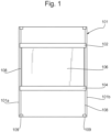
- the rail may be embodied in an architectural covering for example as illustrated schematically in Fig. 1 .
- the architectural covering may be fitted to an architectural structure 101 and includes an upper movable rail 102 and a lower movable rail 104.
- a shade 106 of any appropriate form extends between the upper movable rail 102 and the lower movable rail 104.
- the shade 106 may take form of a roman shade, a venetian blind, a cellular structure etc.
- Each of the upper movable rail 102 and lower movable rail 104 is movable across the architectural structure 101 towards and away from a respective edge. As the upper movable rail 102 and lower movable rail 104 move towards each other, the blind 106 is retracted, for example by concertina or rolling action. When the upper movable rail 102 and lower movable rail 104 are moved apart, the shade 106 is extended across the architectural structure 101.
- cords 108 extend parallel to the side edges of the architectural structure 101 and along the respective movable rails 102, 104.
- the cords 108 are held in place with respect to the upper and lower sides of the architectural structure 101 by means of cord mounts that are engaged to those edges of the architectural structure 101.
- the upper movable rail 102 will be considered in the following example. However, it will be appreciated that the same features, with opposite orientation, can also be considered for the lower movable rail 104.
- the rail 102 has an elongate extent in a first direction which, as illustrated, is horizontal.
- the rail has a base wall 110.
- respective side walls 112 extend substantially perpendicular to the base wall 110. This is illustrated schematically in Fig. 2 , although not illustrated, the rail 102 may be further formed to at least partially fill the space opposite the base wall 110 so as to further enclose the elongate space within the rail 102.
- a cord 108 extends along the length of the rail 102.
- the base wall 110 and side walls 112 define an entrance to the internal space of the rail 102.
- the cord 108 extends into and out of the rail via the entrance and may then extend perpendicular to the rail along the side edges 101a, 101b of the architectural structure 101.
- the cord guiding insert includes a base 116 with an outer surface 116a and an inner surface 116b.
- the outer surface 116a faces outwardly of the assembly away from the longitudinal extent of the rail 102 and may be covered by an end cap to be described later.
- the inner surface 116b faces inwardly of the assembly towards the inner space of the rail 102.
- an upper surface 116c faces upwardly in the same direction as the open side of the rail 102 and a lower surface 116d faces downwardly in the same direction as the closed side of the rail 102.
- An insert portion 118 extends from the inner surface 116b and has a shape and dimensions to match at least part of the inner profile formed in the end of the rail 102. In this way, the cord guiding insert 114 may be mounted at the end of the rail 102 by inserting the insert portion 118 into the entrance formed at the end of the rail 102.
- the base 116 partially closes the entrance of the rail 102, but leaves a space 120 between the base 116 of the cord guiding insert 114 and the base wall 110 of the rail 102.
- This space forms a cord opening out of which the cord 108 may extend
- the outer surface of the base 116 also defines a channel 122 which extends from one side of the base 116 to another.
- the channel 122 extends from the cord opening 120 to guide the cord generally perpendicularly to the extent of the rail 102 and along the edge of the architectural structure when fitted.
- Appropriate openings 126 may be formed at the end of the rail 102 either from the rail 102, the cord guiding insert 114 or a combination thereof.
- the cap 124 is then mounted to the end of the rail 102 by inserting correspondingly shaped protrusions 128. In this way, the cap closes the outer opening of the channel 122 to provide a closed passageway for the cord 108.
- plates of magnetic material are preferably provided in or adjacent the cord holders 109.
- Corresponding magnetic material parts may be provided in the movable rails 102, 104 to magnetically engage those respective rails at the sides of the architectural structure. This is particularly advantageous for the upper movable rail where the magnets may ensure that it is held against the top of the architectural structure. For example, with operation of the lower rail, the tension cords 108 may lose some of their tension, which would otherwise allow the top movable rail 102 to move slightly downwards.
- a retention member 130 having magnetic material is provided with the cord guiding insert 114 as a single unit. In this way, during assembly, it is not necessary to attach separately a retention member to the rail 102. Furthermore, it becomes possible to locate the retention member 130 closer to the end of the rail 102.
- the retention member could similarly be provided as a single unit with a cord guiding insert having a different configuration for guiding the cord 108 out of the rail 102, for example including at least one through hole between the inner and outer surfaces of the base 116 of the cord guiding insert 114, rather than the open space at the lower portion of the base 116 as discussed above.
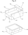
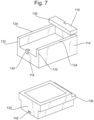
- the arrangement illustrated in Fig. 6 includes such through holes 120a. It also includes a cord guiding insert 114 with two support members 132 extending from the inner surface of the base 116. In the illustrated arrangement, these are formed as part of the insert portion 118, but, in some embodiments, they could be formed separately.
- the two support members 132 together define a support surface 134 for supporting a retention member 130.
- the support surface 134 provided by the two support members 132 faces upwardly and the retention member 130 may rest on that support surface.
- the base 116 is provided with an overhanging and inwardly facing lip 136.
- the retention member 130 has a proximal end for location towards the end of the rail 102 and this proximal end is configured with a feature 138 to fit under the lip 136 of the base 116. In this way, the proximal end of the retention member 130 is engaged in a direction opposite to the support offered by the support surface 134 and the retention member 130 is held in place. With the retention member 130 and cord guiding insert 114 engaged with each other in this way, they can then be mounted as a single unit at the end of the rail 102.
- the illustrated arrangement includes an engagement member 140 configured to engage with and support a distal end of the retention member 130.
- the engagement member 140 includes a resilient member for engaging with a detent or opening 142 at the distal end of the retention member 130.
- the inner profile shape defined by the rail 102 is more complex, though can still be considered to include a base wall 110 with side walls 112 and to define an entrance at the end of the rail 102.
- Portions 112a of the inner profile are configured to receive the insert portion 118 extending from the base 116 of the cord guiding insert 114.
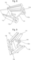
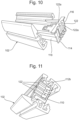
- a pair of insert portions 118 extend on opposite sides of the base 116. These are inserted into the end of the rail 102 as illustrated in Figs. 10 and 11 .
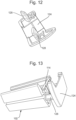
- a plurality of channels 122 are formed in the base 116 of the cord guiding insert 114.
- Adjacent channels 122 are separated by respective walls 122a.
- these walls 122a extend across the opening formed between the base 116 of the cord guiding insert 114 and the base wall 110 of the rail 102 and meet with the base wall 110 so as to define corresponding distinct openings for each respective channel 122.
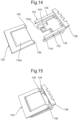
- Fig. 14 illustrates the cord guiding insert 114 in conjunction with a retention member 130 having a magnetic material portion 130a.
- the cord guiding insert 114 includes two support members 132 on opposite respective sides of the cord guiding insert 114, although these support members 132 are provided separately from the insert portions 118, in other embodiments, they could be formed together with the insert portions 118. Respective support surfaces 134 are formed at the upper sides (in the illustrated orientation) of the support members 132 such that, as illustrated in Fig. 15 , the retention member 130 may rest upon and be supported by the support members 132.
- a central portion of the retention member 130 is configured to extend between the support members 132 and has a width corresponding to the width between the support members 132. In this way, the retention member 130 is also supported from lateral movement relative to the longitudinal extent of the support members 132.
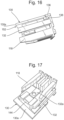
- the base 116 of the cord guiding insert 114 is also provided with a lip 136 which extends inwardly of the rail.
- flanges 138 are provided for extending under the lip 136. This is illustrated most clearly in Fig. 16 .
- an additional support member 132a is provided on the cord guiding insert 114 extending substantially parallel with the two support members 132 at the sides and is configured to extend beneath the retention member 130, in other words on the side of the base wall 110 of the rail 102.
- the engagement member is provided as an aperture 140 in the support member 132a.
- the retention member 130 includes a latch member 144 at the distal end of the retention member 130.
- the latch member 144 is configured to engage the aperture 140 in the support member 132a.
- the latch member 140 may thus prevent the retention member 130 from sliding along the support surfaces 134 of the support members 132 away from the base 116 of the cord guiding insert 114.
- the latch member 144 engages the underside of the additional support member 132a and thereby engages the distal end of the retention member 130 from moving away from the support members 132.
- the retention member 130 and cord guiding insert 114 may thus be provided as a secure single unit.
- the cord guiding insert 114 can additionally define channels running in the first or longitudinal direction of the rail so as to assist with guiding respective cords from the inner space within the rail to the cord opening formed between the cord guiding insert 114 and the rail 102.
- Fig 19 illustrates all, except the end cap 124, of the above components ready for assembly together with two cords 108.
- Fig. 20 illustrates a single unit of the cord guiding insert 114 and retention member 130 fitted to the end of the rail 102 with the end cap 124.
- the retention member 130 forms as overhanging lip 130a at a distal end opposite the flange(s) 138. Together with the support members 132, this defines a slot/opening 152 facing longitudinally along the rail 102.
- the rail 102 may be provided with a cover strip 150 as illustrated in Fig. 20 for covering and enclosing the inner space of the rail 102.
- the cover strip 150 may be slid into and along a pair of oppositely and inwardly facing grooves 154 in the side walls 112.
- the overhanging lip 130a is configured to receive an end of the cover strip 150 beneath the retention member 130 so that the cover strip 150 may engage with the surface of 134 of the support members 132. In this way, with the cover strip 150 engaged in the grooves 154, the end of the cover strip 150 acts to prevent movement of the supports members 132 and hence the cord guiding insert 114 out of the rail 102.
Landscapes
- Engineering & Computer Science (AREA)
- Structural Engineering (AREA)
- Architecture (AREA)
- Civil Engineering (AREA)
- Curtains And Furnishings For Windows Or Doors (AREA)
- Blinds (AREA)
- Door And Window Frames Mounted To Openings (AREA)
Claims (11)
- Schiene (102) zur Verwendung als eine bewegliche Schiene in einer architektonischen Abdeckung, wobei:die Schiene (102) ein erstes Ende beinhaltet und sich in eine erste Richtung von dem ersten Ende erstreckt;die Schiene einen Seilführungseinsatz (114) zur Montage am ersten Ende beinhaltet;an dem ersten Ende die Schiene (102) einen Querschnitt mit einer Innenprofilform aufweist, die einen Eingang in die Schiene (102) definiert,die Schiene (102) einen Innenraum definiert, der sich in die erste Richtung von dem Eingang und zum Aufnehmen eines Seils (108) erstreckt;der Seilführungseinsatz (114) eine Basis (116) mit einer Außenfläche (116a) und einer Innenfläche (116b) gegenüber der Außenfläche (116a) beinhaltet und mindestens einen Einsatzabschnitt (118) beinhaltet, der sich von der Innenfläche (116b) erstreckt;der mindestens eine Einsatzabschnitt (118) eine Außenform aufweist, die mindestens mit einem Teil der Innenprofilform des ersten Endes zusammenpasst;der Seilführungseinsatz (114) konfiguriert ist, um an dem ersten Ende montiert zu sein, wobei der mindestens eine Einsatzabschnitt (118) in den Eingang eingeführt ist, wobei die Außenform des mindestens einen Einsatzabschnitts (118) mindestens mit dem Teil der Innenprofilform zusammenpasst, um mit dem Seilführungseinsatz (114) zum ersten Ende in Eingriff zu sein; dadurch gekennzeichnet, dass:der Seilführungseinsatz (114) konfiguriert ist, um an dem ersten Ende montiert zu sein, wobei die Basis (116) teilweise den Eingang verschließt, um eine Seilöffnung (120) zwischen einer ersten Seite der Basis (116) und der Innenprofilform zu definieren; unddie Außenfläche (116a) der Basis (116) einen Kanal (122) definiert, der sich von der ersten Seite der Basis (116) zu einer gegenüberliegenden zweiten Seite der Basis (116) erstreckt, wobei, mit dem Seilführungseinsatz (114) zum ersten Ende in Eingriff, das Seil (108) aus dem Innenraum herausgeführt werden kann, durch die Seilöffnung (120) und entlang des Kanals (122), der durch die Außenfläche (116a) der Basis (116) definiert wird;die Schiene (102) ein Halteelement (130) beinhaltet, das magnetisches Material aufweist, und zum magnetischen Befestigen der Schiene (102) an einem Endanschlag der architektonischen Abdeckung;der Seilführungseinsatz (114) und das Halteelement (130) zusammengekoppelt sind zur Montage als eine Einheit an dem ersten Ende; undder Seilführungseinsatz (114) mindestens ein Stützelement (132) beinhaltet, das sich von der Innenfläche erstreckt, wobei eine Stützfläche (134) konfiguriert ist, um das Halteelement (130) in einer zweiten Richtung senkrecht zu der ersten Richtung zu stützen, wobei das Halteelement (130) an der Stützfläche (134) positioniert werden kann, wobei der Seilführungseinsatz eine Lippe (136) beinhaltet, die sich von der Innenfläche erstreckt, wobei eine Lippenfläche in eine Richtung zu der Stützfläche (134) gewandt ist, und das Halteelement (130) ein proximales Ende beinhaltet, das konfiguriert ist, um mit der Lippen (136) -fläche der Lippe in Eingriff zu sein, sodass das proximale Ende in einer Richtung entgegengesetzt der zweiten Richtung gestützt wird.
- Schiene nach Anspruch 1, wobei sich der mindestens eine Einsatzabschnitt (118) im Wesentlichen senkrecht zu der Innenfläche (116b) erstreckt.
- Schiene nach Anspruch 1 oder 2, wobei die Innenfläche (116b) und die Außenfläche (116a) im Wesentlichen parallel sind.
- Schiene nach einem der Ansprüche 1 bis 3, wobei mindestens eines aus: die Außenfläche (116a) der Basis (116) definiert einen zusätzlichen Kanal (122), der sich von der ersten Seite zu der zweiten Seite zum Führen eines zusätzlichen Seils (108) jeweils erstreckt; und die Basis (116) beinhaltet eine Wand (122a) zwischen dem Kanal (122) und dem zusätzlichen Kanal (122) und definiert diese, und die Wand (122a) erstreckt sich über die erste Seite hinaus mindestens teilweise über die Seilöffnung (120), um jeweilige Seilwege durch die Seilöffnung (120) zu definieren, wobei sich die Wand (122a) über die Öffnung (120) erstreckt, um mit der Innenprofilform zusammenzutreffen.
- Schiene nach einem der Ansprüche 1 bis 4, wobei die Schiene (102) mindestens eine Basiswand (110) beinhaltet, die sich in die erste Richtung und eine zweite Richtung senkrecht zu der ersten Richtung erstreckt und, an zwei im Wesentlichen gegenüberliegenden Kanten der Basiswand (110) in der zweiten Richtung, jeweilige Seitenwände (112) beinhaltet, die sich in die erste Richtung und in im Wesentlichen eine dritte Richtung senkrecht zu der ersten und zweiten Richtung erstreckt, und wobei die Basiswand (110) und die zwei Seitenwände (112) den Querschnitt mit der Innenprofilform bilden, die den Eingang definiert, wobei die Basis (116) des Seilführungseinsatzes (114) die Seilöffnung (120) mit der Basiswand (110) definiert, indem Platz in der dritten Richtung gelassen wird, und der Kanal (122) erstreckt sich von der ersten Seite zu der zweiten Seite im Wesentlichen in die dritte Richtung.
- Schiene nach einem der Ansprüche 1 bis 5, wobei der mindestens eine Einsatzabschnitt (118) eine Vielzahl von Abschnitten beinhaltet, die sich von unterschiedlichen Teilen der Innenfläche (116b) erstrecken, und konfiguriert ist, um mit unterschiedlichen jeweiligen Teilen der Innenprofilform zusammenzupassen.
- Schiene nach einem der Ansprüche 1 bis 6, wobei der Seilführungseinsatz (114) konfiguriert ist, um mit dem Halteelement (130) in Eingriff zu sein und mit dem Halteelement (130) an dem ersten Ende der Schiene (102) in Eingriff zu sein.
- Schiene nach einem der Ansprüche 1 bis 7, wobei das Stützelement (132) und das Halteelement (130) konfiguriert sind, um miteinander zu kooperieren, um das Halteelement (130) in gegenüberliegenden dritten Richtungen senkrecht zu der ersten und zweiten Richtung zu stützen, wobei das Stützelement (132) zwei im Wesentlichen parallele Stützschienen beinhalten kann, die zusammen die Stützfläche (134) bilden, und das Halteelement (130) kann ein Profil aufweisen, das Abmessungen aufweist, um gegen beide Stützschienen zum Stützen in der zweiten Richtung und zwischen jeweilige Stützschienen zum Stützen in den entgegengesetzten dritten Richtungen zu passen.
- Schiene nach einem der Ansprüche 1 bis 8, wobei das Stützelement (132) ein Eingriffselement beinhaltet, das konfiguriert ist, um mit einem distalen Ende des Halteelements (130) in Eingriff zu sein und dieses zu stützen, gegenüber dem proximalen Ende, in der Richtung entgegengesetzt zu der zweiten Richtung, wobei das Stützelement (132) einen Arm beinhalten kann, der sich von der Innenfläche der Basis zu einem Endteil erstreckt, konfiguriert, um sich in die erste Richtung auf derselben Seite des Halteelements (130) wie das Stützelement (132) zu erstrecken und das Eingriffselement am Endteil beinhaltet, und wobei das Halteelement (130) ein Verriegelungselement am distalen Ende beinhalten kann, das konfiguriert ist, um sich in die entgegengesetzte Richtung zur zweiten Richtung zu erstrecken, und das Eingriffselement kann eine Öffnung beinhalten, die konfiguriert ist, um mit dem Verriegelungselement in Eingriff zu sein und um das distale Ende in der Richtung entgegengesetzt zu der zweiten Richtung zu stützen.
- Abdeckung einer architektonischen Öffnung, einschließlich mindestens einer Schiene (102) nach einem vorhergehenden Anspruch, die angeordnet ist, um beweglich über eine architektonische Struktur montiert zu sein und konfiguriert ist, um ein Rollo aus- und einzufahren, wobei die Abdeckung einer architektonischen Öffnung mindestens ein Seil (108) beinhalten kann, das sich entlang des Innenraums und daraus heraus, durch die Seilöffnung (120) und entlang des Kanals (122) erstreckt, definiert durch die Außenfläche der Basis (116), und einen Endanschlag beinhalten kann, einschließlich magnetischen Materials, und konfiguriert, um an einer Oberfläche der architektonischen Struktur parallel mit der Schiene (102) montiert zu sein und konfiguriert, um mit der Schiene (102) gegen diese Oberfläche in Eingriff zu sein.
- Verfahren des Führens von mindestens einem Seil (108) aus dem Ende der beweglichen Schiene (102) einer architektonischen Abdeckung, wobei das Verfahren Folgendes beinhaltet:Bereitstellen eines Seilführungseinsatzes (114) zum Montieren in einem ersten Ende der beweglichen Schiene (102);Bereitstellen des Seilführungseinsatzes (114) mit einer Basis (116), die eine Außenfläche (116a) und eine Innenfläche (116b) gegenüber der Außenfläche (116a) aufweist und mindestens einen Einsatzabschnitt (118) aufweist, der sich von der Innenfläche (116b) erstreckt; undAnpassen der Außenfläche des mindestens einen Einsatzabschnitts (118) an mindestens einen Teil der Innenprofilform des ersten Endes der beweglichen Schiene (102) und Montieren des Seilführungseinsatzes (114) an dem ersten Ende der beweglichen Schiene (102) durch Einführen des mindestens einen Einsatzabschnitts (118) in das erste Ende; gekennzeichnet durch:Anordnen der Basis (116), um den Eingang teilweise zu verschließen, der durch die bewegliche Schiene (102) definiert wird, am ersten Ende, um eine Seilöffnung (120) zwischen einer ersten Seite der Basis (116) und der Innenprofilform zu definieren; undDefinieren, in der Außenfläche der Basis (116), eines Kanals (122), der sich von der ersten Seite der Basis (116) zu einer gegenüberliegenden Seite der Basis (116) erstreckt, wobei, mit dem Seilführungseinsatz (114) am ersten Ende montiert, das Seil (108) aus der beweglichen Schiene (102) herausgeführt wird, durch die Seilöffnung (120) und entlang des Kanals (122), der durch die Außenfläche (116b) der Basis (116) definiert wird;Bereitstellen eines Halteelements (130), das magnetisches Material aufweist, und zum magnetischen Befestigen der Schiene (102) an einem Endanschlag der architektonischen Abdeckung;Zusammenkoppeln des Seilführungseinsatzes (114) und des Halteelements (130) zum Montieren als eine Einheit am ersten Ende;Bereitstellen des Seilführungseinsatzes (114) mit:mindestens einem Stützelement (132), das sich von der Innenfläche erstreckt, wobei eine Stützfläche (134) konfiguriert ist, um das Halteelement (130) in einer zweiten Richtung senkrecht zu der ersten Richtung zu stützen, wobei das Halteelement (130) an der Stützfläche (134) positioniert werden kann, undeiner Lippe (136), die sich von der Innenfläche erstreckt, wobei eine Lippenfläche in eine Richtung zu der Stützfläche (134) gewandt ist; undBereitstellen des Halteelements (130) mit einem proximalen Ende, das konfiguriert ist, um mit der Lippen (136) -fläche der Lippe in Eingriff zu sein, sodass das proximale Ende in einer Richtung entgegengesetzt der zweiten Richtung gestützt wird.
Priority Applications (1)
| Application Number | Priority Date | Filing Date | Title |
|---|---|---|---|
| PL17204739.1T PL3330475T5 (pl) | 2016-12-01 | 2017-11-30 | Szyna dla osłony otworu architektonicznego |
Applications Claiming Priority (1)
| Application Number | Priority Date | Filing Date | Title |
|---|---|---|---|
| EP16201779 | 2016-12-01 |
Publications (4)
| Publication Number | Publication Date |
|---|---|
| EP3330475A2 EP3330475A2 (de) | 2018-06-06 |
| EP3330475A3 EP3330475A3 (de) | 2018-11-21 |
| EP3330475B1 EP3330475B1 (de) | 2021-05-12 |
| EP3330475B2 true EP3330475B2 (de) | 2024-07-17 |
Family
ID=57485322
Family Applications (1)
| Application Number | Title | Priority Date | Filing Date |
|---|---|---|---|
| EP17204739.1A Active EP3330475B2 (de) | 2016-12-01 | 2017-11-30 | Schiene für eine architektonische öffnungsabdeckung |
Country Status (4)
| Country | Link |
|---|---|
| US (1) | US10641038B2 (de) |
| EP (1) | EP3330475B2 (de) |
| CA (1) | CA2987509A1 (de) |
| PL (1) | PL3330475T5 (de) |
Families Citing this family (10)
| Publication number | Priority date | Publication date | Assignee | Title |
|---|---|---|---|---|
| US9482048B2 (en) | 2011-03-07 | 2016-11-01 | Hunter Douglas, Inc. | Control for movable rail |
| US9759008B2 (en) * | 2012-12-06 | 2017-09-12 | Hunter Douglas Inc. | End cap for a rail for a window covering |
| FI127923B (fi) * | 2018-02-27 | 2019-05-31 | Suomen Visor Oy | Aurinkosuojan reunakiskon päätykappale ja aurinkosuoja |
| DE102018124462A1 (de) * | 2018-10-04 | 2020-04-09 | Mhz Hachtel Gmbh & Co. Kg | Glasleiste |
| US11891855B2 (en) * | 2020-01-28 | 2024-02-06 | Levolor, Inc. | Leveling assembly for adjusting the levelness of a bottom rail of a covering for an architectural structure |
| TWM603727U (zh) * | 2020-05-19 | 2020-11-11 | 黃昱瑋 | 提拉式窗簾組 |
| DE202021106651U1 (de) | 2021-12-07 | 2023-03-08 | Achim Lienert | Befestigungssystem für eine Beschattungsanlage |
| DE102021213852A1 (de) | 2021-12-07 | 2023-06-07 | Achim Lienert | Befestigungssystem für eine Beschattungsanlage |
| US12571252B2 (en) | 2022-03-11 | 2026-03-10 | Hunter Douglas Inc. | Valance assembly and related coverings for an architectural structure |
| US12312861B2 (en) * | 2022-04-15 | 2025-05-27 | Ingo Scholz | Child safe tension corded shade |
Citations (12)
| Publication number | Priority date | Publication date | Assignee | Title |
|---|---|---|---|---|
| US20030075285A1 (en) † | 2000-02-08 | 2003-04-24 | Hunter Douglas Inc. | Framed covering for architectural opening |
| US20050092446A1 (en) † | 2003-10-29 | 2005-05-05 | Leslie Ni | Cordless Venetian blind structure |
| EP1696099A1 (de) † | 2005-02-24 | 2006-08-30 | LEHA Vorhangschienen Werner Hanisch KG | Jalousie |
| EP1783315A2 (de) † | 2005-11-03 | 2007-05-09 | VKR Holding A/S | Schnurhalter und Endkappe für eine Verschattungsanlage sowie Verschattungsanlage |
| DE102006000964A1 (de) † | 2006-01-07 | 2007-07-12 | Warema Kunststofftechnik Und Maschinenbau Gmbh | Endkappe für Schienenprofil |
| US20090014133A1 (en) † | 2007-07-11 | 2009-01-15 | Shih-Ming Lin | Multi-Section Curtain |
| WO2009122222A1 (en) † | 2008-04-01 | 2009-10-08 | Zoran Maksan | Venetian blinds with magnetic controller for regulation |
| EP1526246B1 (de) † | 2003-10-24 | 2010-06-09 | Hunter Douglas Industries B.V. | Montagevorrichtung für ein Führungsseil |
| DE102011053648A1 (de) † | 2011-09-15 | 2013-03-21 | Achim Lienert | Schnurspanner zum Spannen einer Schnur an Beschattungsanlagen |
| DE202015105004U1 (de) † | 2015-09-21 | 2016-01-21 | Sundean And Dr. Pan Industries Inc. | Drehbares Baugruppensystem für Jalousien ohne Zugschnur und Wendestab |
| DE202016102098U1 (de) † | 2016-04-21 | 2016-05-16 | Mhz Hachtel Gmbh & Co. Kg | Plisseeanlage mit Magnetelement |
| DE102014018562A1 (de) † | 2014-12-15 | 2016-06-16 | Blöcker Zweigniederlassung der Hunter Douglas Holding GmbH & Co. KG | Verstellbare Abdeckvorrichtung für eine Fläche |
Family Cites Families (7)
| Publication number | Priority date | Publication date | Assignee | Title |
|---|---|---|---|---|
| US4842034A (en) * | 1985-10-09 | 1989-06-27 | Elkhart Door, Incorporated | Window shade |
| DE9411839U1 (de) | 1994-07-21 | 1995-11-23 | HANSA Sicht- und Sonnenschutz GmbH, 22523 Hamburg | Faltenstore |
| US7063122B2 (en) * | 2002-03-20 | 2006-06-20 | Hunter Douglas Inc. | Bottom-up/top-down retractable cellular shade |
| CN2862889Y (zh) | 2005-11-18 | 2007-01-31 | 谢南平 | 防蚊折叠窗帘/门帘 |
| AT9083U1 (de) | 2006-02-09 | 2007-04-15 | Leha Vorhangschienen Werner Ha | Jalousie |
| DE202009000093U1 (de) | 2009-02-06 | 2009-04-30 | Lienert, Achim | Beschattungseinrichtung für Fenster- oder Türöffnungen |
| CH707200A2 (de) * | 2012-11-09 | 2014-05-15 | Beat Guhl | Führungsanordnung für einen Behang. |
-
2017
- 2017-11-27 US US15/822,258 patent/US10641038B2/en active Active
- 2017-11-30 EP EP17204739.1A patent/EP3330475B2/de active Active
- 2017-11-30 PL PL17204739.1T patent/PL3330475T5/pl unknown
- 2017-12-01 CA CA2987509A patent/CA2987509A1/en active Pending
Patent Citations (12)
| Publication number | Priority date | Publication date | Assignee | Title |
|---|---|---|---|---|
| US20030075285A1 (en) † | 2000-02-08 | 2003-04-24 | Hunter Douglas Inc. | Framed covering for architectural opening |
| EP1526246B1 (de) † | 2003-10-24 | 2010-06-09 | Hunter Douglas Industries B.V. | Montagevorrichtung für ein Führungsseil |
| US20050092446A1 (en) † | 2003-10-29 | 2005-05-05 | Leslie Ni | Cordless Venetian blind structure |
| EP1696099A1 (de) † | 2005-02-24 | 2006-08-30 | LEHA Vorhangschienen Werner Hanisch KG | Jalousie |
| EP1783315A2 (de) † | 2005-11-03 | 2007-05-09 | VKR Holding A/S | Schnurhalter und Endkappe für eine Verschattungsanlage sowie Verschattungsanlage |
| DE102006000964A1 (de) † | 2006-01-07 | 2007-07-12 | Warema Kunststofftechnik Und Maschinenbau Gmbh | Endkappe für Schienenprofil |
| US20090014133A1 (en) † | 2007-07-11 | 2009-01-15 | Shih-Ming Lin | Multi-Section Curtain |
| WO2009122222A1 (en) † | 2008-04-01 | 2009-10-08 | Zoran Maksan | Venetian blinds with magnetic controller for regulation |
| DE102011053648A1 (de) † | 2011-09-15 | 2013-03-21 | Achim Lienert | Schnurspanner zum Spannen einer Schnur an Beschattungsanlagen |
| DE102014018562A1 (de) † | 2014-12-15 | 2016-06-16 | Blöcker Zweigniederlassung der Hunter Douglas Holding GmbH & Co. KG | Verstellbare Abdeckvorrichtung für eine Fläche |
| DE202015105004U1 (de) † | 2015-09-21 | 2016-01-21 | Sundean And Dr. Pan Industries Inc. | Drehbares Baugruppensystem für Jalousien ohne Zugschnur und Wendestab |
| DE202016102098U1 (de) † | 2016-04-21 | 2016-05-16 | Mhz Hachtel Gmbh & Co. Kg | Plisseeanlage mit Magnetelement |
Non-Patent Citations (1)
| Title |
|---|
| ANONYMOUS: "Pleated Blinds", BENTHIN PRODUCT BROCHURE, BENTHIN, 1 January 2012 (2012-01-01), pages 1 - 12 † |
Also Published As
| Publication number | Publication date |
|---|---|
| US20180155983A1 (en) | 2018-06-07 |
| EP3330475A2 (de) | 2018-06-06 |
| PL3330475T5 (pl) | 2025-11-17 |
| CA2987509A1 (en) | 2018-06-01 |
| US10641038B2 (en) | 2020-05-05 |
| EP3330475A3 (de) | 2018-11-21 |
| PL3330475T3 (pl) | 2021-11-08 |
| EP3330475B1 (de) | 2021-05-12 |
Similar Documents
| Publication | Publication Date | Title |
|---|---|---|
| EP3330475B2 (de) | Schiene für eine architektonische öffnungsabdeckung | |
| US9708844B2 (en) | Sliding door closing device | |
| US9784314B2 (en) | Three-section synchronous concealed slide rail | |
| US6155661A (en) | Drawer slide latch | |
| US8905468B2 (en) | Sunshade apparatus | |
| US7967399B1 (en) | Linearly actuated chassis lock for a drawer slide | |
| JP7030992B2 (ja) | 引出しガイド | |
| KR101268912B1 (ko) | 가구힌지의 가구도어 위치 조절장치 | |
| KR200483878Y1 (ko) | 커튼러너의 삽입 및 분리가 용이한 커튼레일 조립체 | |
| CA3019068C (en) | SLIDING AND TILTING TRAY, SLIDING AND TRAY USING IT | |
| JP6490089B2 (ja) | スライド式ドア用の嵌合具 | |
| US10709033B2 (en) | Coupling assembly and cable management device thereof | |
| US20070126324A1 (en) | Refrigerator rail assembly and refrigerator storage box extracting/retracting apparatus having the same | |
| KR20180006015A (ko) | 커튼레일 조립체 | |
| KR20170030547A (ko) | 슬라이딩 도어를 위한 피팅 | |
| US20070040484A1 (en) | Interlocking structure of drawers | |
| CA2433305A1 (en) | Device for fastening a guide rail to a wall | |
| JP6456845B2 (ja) | ガイドレールを介して誘導方向に家具部品を誘導するための走行部、および家具用建具 | |
| ES2924327T3 (es) | Sistema de cajón con guía de extracción en la que se pueden montar diferentes sistemas de cajón | |
| KR101717732B1 (ko) | 3중 슬라이딩 도어 체결장치 | |
| US20080092454A1 (en) | Sliding Screen Door | |
| EP2511467B1 (de) | Halterung einer Kordel, insbesondere zur Führung eines Stoffrollladens | |
| KR101704585B1 (ko) | 3연동 자동체결 시스템도어 | |
| EP3330476A1 (de) | Spannseilmontage | |
| EP3409873A1 (de) | Spannseilmontagevorrichtung für eine architektonische abdeckung |
Legal Events
| Date | Code | Title | Description |
|---|---|---|---|
| PUAI | Public reference made under article 153(3) epc to a published international application that has entered the european phase |
Free format text: ORIGINAL CODE: 0009012 |
|
| STAA | Information on the status of an ep patent application or granted ep patent |
Free format text: STATUS: THE APPLICATION HAS BEEN PUBLISHED |
|
| AK | Designated contracting states |
Kind code of ref document: A2 Designated state(s): AL AT BE BG CH CY CZ DE DK EE ES FI FR GB GR HR HU IE IS IT LI LT LU LV MC MK MT NL NO PL PT RO RS SE SI SK SM TR |
|
| AX | Request for extension of the european patent |
Extension state: BA ME |
|
| PUAL | Search report despatched |
Free format text: ORIGINAL CODE: 0009013 |
|
| AK | Designated contracting states |
Kind code of ref document: A3 Designated state(s): AL AT BE BG CH CY CZ DE DK EE ES FI FR GB GR HR HU IE IS IT LI LT LU LV MC MK MT NL NO PL PT RO RS SE SI SK SM TR |
|
| AX | Request for extension of the european patent |
Extension state: BA ME |
|
| RIC1 | Information provided on ipc code assigned before grant |
Ipc: E06B 9/388 20060101ALI20181018BHEP Ipc: E06B 9/327 20060101AFI20181018BHEP |
|
| TPAC | Observations filed by third parties |
Free format text: ORIGINAL CODE: EPIDOSNTIPA |
|
| STAA | Information on the status of an ep patent application or granted ep patent |
Free format text: STATUS: REQUEST FOR EXAMINATION WAS MADE |
|
| 17P | Request for examination filed |
Effective date: 20190520 |
|
| RBV | Designated contracting states (corrected) |
Designated state(s): AL AT BE BG CH CY CZ DE DK EE ES FI FR GB GR HR HU IE IS IT LI LT LU LV MC MK MT NL NO PL PT RO RS SE SI SK SM TR |
|
| GRAP | Despatch of communication of intention to grant a patent |
Free format text: ORIGINAL CODE: EPIDOSNIGR1 |
|
| STAA | Information on the status of an ep patent application or granted ep patent |
Free format text: STATUS: GRANT OF PATENT IS INTENDED |
|
| INTG | Intention to grant announced |
Effective date: 20201210 |
|
| GRAS | Grant fee paid |
Free format text: ORIGINAL CODE: EPIDOSNIGR3 |
|
| GRAA | (expected) grant |
Free format text: ORIGINAL CODE: 0009210 |
|
| STAA | Information on the status of an ep patent application or granted ep patent |
Free format text: STATUS: THE PATENT HAS BEEN GRANTED |
|
| AK | Designated contracting states |
Kind code of ref document: B1 Designated state(s): AL AT BE BG CH CY CZ DE DK EE ES FI FR GB GR HR HU IE IS IT LI LT LU LV MC MK MT NL NO PL PT RO RS SE SI SK SM TR |
|
| REG | Reference to a national code |
Ref country code: GB Ref legal event code: FG4D |
|
| REG | Reference to a national code |
Ref country code: CH Ref legal event code: EP |
|
| REG | Reference to a national code |
Ref country code: DE Ref legal event code: R096 Ref document number: 602017038460 Country of ref document: DE |
|
| REG | Reference to a national code |
Ref country code: IE Ref legal event code: FG4D |
|
| REG | Reference to a national code |
Ref country code: AT Ref legal event code: REF Ref document number: 1392277 Country of ref document: AT Kind code of ref document: T Effective date: 20210615 |
|
| REG | Reference to a national code |
Ref country code: NL Ref legal event code: FP |
|
| REG | Reference to a national code |
Ref country code: LT Ref legal event code: MG9D |
|
| REG | Reference to a national code |
Ref country code: AT Ref legal event code: MK05 Ref document number: 1392277 Country of ref document: AT Kind code of ref document: T Effective date: 20210512 |
|
| PG25 | Lapsed in a contracting state [announced via postgrant information from national office to epo] |
Ref country code: AT Free format text: LAPSE BECAUSE OF FAILURE TO SUBMIT A TRANSLATION OF THE DESCRIPTION OR TO PAY THE FEE WITHIN THE PRESCRIBED TIME-LIMIT Effective date: 20210512 Ref country code: BG Free format text: LAPSE BECAUSE OF FAILURE TO SUBMIT A TRANSLATION OF THE DESCRIPTION OR TO PAY THE FEE WITHIN THE PRESCRIBED TIME-LIMIT Effective date: 20210812 Ref country code: HR Free format text: LAPSE BECAUSE OF FAILURE TO SUBMIT A TRANSLATION OF THE DESCRIPTION OR TO PAY THE FEE WITHIN THE PRESCRIBED TIME-LIMIT Effective date: 20210512 Ref country code: FI Free format text: LAPSE BECAUSE OF FAILURE TO SUBMIT A TRANSLATION OF THE DESCRIPTION OR TO PAY THE FEE WITHIN THE PRESCRIBED TIME-LIMIT Effective date: 20210512 Ref country code: LT Free format text: LAPSE BECAUSE OF FAILURE TO SUBMIT A TRANSLATION OF THE DESCRIPTION OR TO PAY THE FEE WITHIN THE PRESCRIBED TIME-LIMIT Effective date: 20210512 |
|
| PG25 | Lapsed in a contracting state [announced via postgrant information from national office to epo] |
Ref country code: GR Free format text: LAPSE BECAUSE OF FAILURE TO SUBMIT A TRANSLATION OF THE DESCRIPTION OR TO PAY THE FEE WITHIN THE PRESCRIBED TIME-LIMIT Effective date: 20210813 Ref country code: LV Free format text: LAPSE BECAUSE OF FAILURE TO SUBMIT A TRANSLATION OF THE DESCRIPTION OR TO PAY THE FEE WITHIN THE PRESCRIBED TIME-LIMIT Effective date: 20210512 Ref country code: IS Free format text: LAPSE BECAUSE OF FAILURE TO SUBMIT A TRANSLATION OF THE DESCRIPTION OR TO PAY THE FEE WITHIN THE PRESCRIBED TIME-LIMIT Effective date: 20210912 Ref country code: RS Free format text: LAPSE BECAUSE OF FAILURE TO SUBMIT A TRANSLATION OF THE DESCRIPTION OR TO PAY THE FEE WITHIN THE PRESCRIBED TIME-LIMIT Effective date: 20210512 Ref country code: SE Free format text: LAPSE BECAUSE OF FAILURE TO SUBMIT A TRANSLATION OF THE DESCRIPTION OR TO PAY THE FEE WITHIN THE PRESCRIBED TIME-LIMIT Effective date: 20210512 Ref country code: PT Free format text: LAPSE BECAUSE OF FAILURE TO SUBMIT A TRANSLATION OF THE DESCRIPTION OR TO PAY THE FEE WITHIN THE PRESCRIBED TIME-LIMIT Effective date: 20210913 Ref country code: NO Free format text: LAPSE BECAUSE OF FAILURE TO SUBMIT A TRANSLATION OF THE DESCRIPTION OR TO PAY THE FEE WITHIN THE PRESCRIBED TIME-LIMIT Effective date: 20210812 |
|
| PG25 | Lapsed in a contracting state [announced via postgrant information from national office to epo] |
Ref country code: SM Free format text: LAPSE BECAUSE OF FAILURE TO SUBMIT A TRANSLATION OF THE DESCRIPTION OR TO PAY THE FEE WITHIN THE PRESCRIBED TIME-LIMIT Effective date: 20210512 Ref country code: SK Free format text: LAPSE BECAUSE OF FAILURE TO SUBMIT A TRANSLATION OF THE DESCRIPTION OR TO PAY THE FEE WITHIN THE PRESCRIBED TIME-LIMIT Effective date: 20210512 Ref country code: RO Free format text: LAPSE BECAUSE OF FAILURE TO SUBMIT A TRANSLATION OF THE DESCRIPTION OR TO PAY THE FEE WITHIN THE PRESCRIBED TIME-LIMIT Effective date: 20210512 Ref country code: ES Free format text: LAPSE BECAUSE OF FAILURE TO SUBMIT A TRANSLATION OF THE DESCRIPTION OR TO PAY THE FEE WITHIN THE PRESCRIBED TIME-LIMIT Effective date: 20210512 Ref country code: EE Free format text: LAPSE BECAUSE OF FAILURE TO SUBMIT A TRANSLATION OF THE DESCRIPTION OR TO PAY THE FEE WITHIN THE PRESCRIBED TIME-LIMIT Effective date: 20210512 Ref country code: CZ Free format text: LAPSE BECAUSE OF FAILURE TO SUBMIT A TRANSLATION OF THE DESCRIPTION OR TO PAY THE FEE WITHIN THE PRESCRIBED TIME-LIMIT Effective date: 20210512 Ref country code: DK Free format text: LAPSE BECAUSE OF FAILURE TO SUBMIT A TRANSLATION OF THE DESCRIPTION OR TO PAY THE FEE WITHIN THE PRESCRIBED TIME-LIMIT Effective date: 20210512 |
|
| REG | Reference to a national code |
Ref country code: DE Ref legal event code: R026 Ref document number: 602017038460 Country of ref document: DE |
|
| PLBI | Opposition filed |
Free format text: ORIGINAL CODE: 0009260 |
|
| PLAX | Notice of opposition and request to file observation + time limit sent |
Free format text: ORIGINAL CODE: EPIDOSNOBS2 |
|
| 26 | Opposition filed |
Opponent name: VON LIERES BRACHMANN SCHULZE Effective date: 20220209 |
|
| PG25 | Lapsed in a contracting state [announced via postgrant information from national office to epo] |
Ref country code: IS Free format text: LAPSE BECAUSE OF FAILURE TO SUBMIT A TRANSLATION OF THE DESCRIPTION OR TO PAY THE FEE WITHIN THE PRESCRIBED TIME-LIMIT Effective date: 20210912 Ref country code: AL Free format text: LAPSE BECAUSE OF FAILURE TO SUBMIT A TRANSLATION OF THE DESCRIPTION OR TO PAY THE FEE WITHIN THE PRESCRIBED TIME-LIMIT Effective date: 20210512 |
|
| PG25 | Lapsed in a contracting state [announced via postgrant information from national office to epo] |
Ref country code: MC Free format text: LAPSE BECAUSE OF FAILURE TO SUBMIT A TRANSLATION OF THE DESCRIPTION OR TO PAY THE FEE WITHIN THE PRESCRIBED TIME-LIMIT Effective date: 20210512 |
|
| REG | Reference to a national code |
Ref country code: CH Ref legal event code: PL |
|
| PLBB | Reply of patent proprietor to notice(s) of opposition received |
Free format text: ORIGINAL CODE: EPIDOSNOBS3 |
|
| PG25 | Lapsed in a contracting state [announced via postgrant information from national office to epo] |
Ref country code: LU Free format text: LAPSE BECAUSE OF NON-PAYMENT OF DUE FEES Effective date: 20211130 Ref country code: IT Free format text: LAPSE BECAUSE OF FAILURE TO SUBMIT A TRANSLATION OF THE DESCRIPTION OR TO PAY THE FEE WITHIN THE PRESCRIBED TIME-LIMIT Effective date: 20210512 Ref country code: BE Free format text: LAPSE BECAUSE OF NON-PAYMENT OF DUE FEES Effective date: 20211130 |
|
| REG | Reference to a national code |
Ref country code: BE Ref legal event code: MM Effective date: 20211130 |
|
| PG25 | Lapsed in a contracting state [announced via postgrant information from national office to epo] |
Ref country code: IE Free format text: LAPSE BECAUSE OF NON-PAYMENT OF DUE FEES Effective date: 20211130 |
|
| PG25 | Lapsed in a contracting state [announced via postgrant information from national office to epo] |
Ref country code: FR Free format text: LAPSE BECAUSE OF NON-PAYMENT OF DUE FEES Effective date: 20211130 |
|
| PG25 | Lapsed in a contracting state [announced via postgrant information from national office to epo] |
Ref country code: HU Free format text: LAPSE BECAUSE OF FAILURE TO SUBMIT A TRANSLATION OF THE DESCRIPTION OR TO PAY THE FEE WITHIN THE PRESCRIBED TIME-LIMIT; INVALID AB INITIO Effective date: 20171130 |
|
| P01 | Opt-out of the competence of the unified patent court (upc) registered |
Effective date: 20230331 |
|
| PG25 | Lapsed in a contracting state [announced via postgrant information from national office to epo] |
Ref country code: CY Free format text: LAPSE BECAUSE OF FAILURE TO SUBMIT A TRANSLATION OF THE DESCRIPTION OR TO PAY THE FEE WITHIN THE PRESCRIBED TIME-LIMIT Effective date: 20210512 |
|
| PG25 | Lapsed in a contracting state [announced via postgrant information from national office to epo] |
Ref country code: LI Free format text: LAPSE BECAUSE OF NON-PAYMENT OF DUE FEES Effective date: 20220630 Ref country code: CH Free format text: LAPSE BECAUSE OF NON-PAYMENT OF DUE FEES Effective date: 20220630 |
|
| APBM | Appeal reference recorded |
Free format text: ORIGINAL CODE: EPIDOSNREFNO |
|
| APBP | Date of receipt of notice of appeal recorded |
Free format text: ORIGINAL CODE: EPIDOSNNOA2O |
|
| APAH | Appeal reference modified |
Free format text: ORIGINAL CODE: EPIDOSCREFNO |
|
| RAP4 | Party data changed (patent owner data changed or rights of a patent transferred) |
Owner name: HUNTER DOUGLAS INDUSTRIES B.V. |
|
| APBU | Appeal procedure closed |
Free format text: ORIGINAL CODE: EPIDOSNNOA9O |
|
| PG25 | Lapsed in a contracting state [announced via postgrant information from national office to epo] |
Ref country code: MK Free format text: LAPSE BECAUSE OF FAILURE TO SUBMIT A TRANSLATION OF THE DESCRIPTION OR TO PAY THE FEE WITHIN THE PRESCRIBED TIME-LIMIT Effective date: 20210512 |
|
| PUAH | Patent maintained in amended form |
Free format text: ORIGINAL CODE: 0009272 |
|
| STAA | Information on the status of an ep patent application or granted ep patent |
Free format text: STATUS: PATENT MAINTAINED AS AMENDED |
|
| PG25 | Lapsed in a contracting state [announced via postgrant information from national office to epo] |
Ref country code: TR Free format text: LAPSE BECAUSE OF FAILURE TO SUBMIT A TRANSLATION OF THE DESCRIPTION OR TO PAY THE FEE WITHIN THE PRESCRIBED TIME-LIMIT Effective date: 20210512 |
|
| 27A | Patent maintained in amended form |
Effective date: 20240717 |
|
| AK | Designated contracting states |
Kind code of ref document: B2 Designated state(s): AL AT BE BG CH CY CZ DE DK EE ES FI FR GB GR HR HU IE IS IT LI LT LU LV MC MK MT NL NO PL PT RO RS SE SI SK SM TR |
|
| REG | Reference to a national code |
Ref country code: DE Ref legal event code: R102 Ref document number: 602017038460 Country of ref document: DE |
|
| REG | Reference to a national code |
Ref country code: NL Ref legal event code: FP |
|
| PG25 | Lapsed in a contracting state [announced via postgrant information from national office to epo] |
Ref country code: MT Free format text: LAPSE BECAUSE OF FAILURE TO SUBMIT A TRANSLATION OF THE DESCRIPTION OR TO PAY THE FEE WITHIN THE PRESCRIBED TIME-LIMIT Effective date: 20210512 |
|
| PGFP | Annual fee paid to national office [announced via postgrant information from national office to epo] |
Ref country code: NL Payment date: 20251124 Year of fee payment: 9 |
|
| PGFP | Annual fee paid to national office [announced via postgrant information from national office to epo] |
Ref country code: DE Payment date: 20251126 Year of fee payment: 9 |
|
| PGFP | Annual fee paid to national office [announced via postgrant information from national office to epo] |
Ref country code: GB Payment date: 20251125 Year of fee payment: 9 |
|
| PGFP | Annual fee paid to national office [announced via postgrant information from national office to epo] |
Ref country code: PL Payment date: 20251121 Year of fee payment: 9 |