EP3335839B1 - Machine-outil portative - Google Patents
Machine-outil portative Download PDFInfo
- Publication number
- EP3335839B1 EP3335839B1 EP17207416.3A EP17207416A EP3335839B1 EP 3335839 B1 EP3335839 B1 EP 3335839B1 EP 17207416 A EP17207416 A EP 17207416A EP 3335839 B1 EP3335839 B1 EP 3335839B1
- Authority
- EP
- European Patent Office
- Prior art keywords
- blocking
- gear
- switching
- transmission
- locking
- Prior art date
- Legal status (The legal status is an assumption and is not a legal conclusion. Google has not performed a legal analysis and makes no representation as to the accuracy of the status listed.)
- Active
Links
Images


Classifications
-
- B—PERFORMING OPERATIONS; TRANSPORTING
- B25—HAND TOOLS; PORTABLE POWER-DRIVEN TOOLS; MANIPULATORS
- B25F—COMBINATION OR MULTI-PURPOSE TOOLS NOT OTHERWISE PROVIDED FOR; DETAILS OR COMPONENTS OF PORTABLE POWER-DRIVEN TOOLS NOT PARTICULARLY RELATED TO THE OPERATIONS PERFORMED AND NOT OTHERWISE PROVIDED FOR
- B25F5/00—Details or components of portable power-driven tools not particularly related to the operations performed and not otherwise provided for
- B25F5/001—Gearings, speed selectors, clutches or the like specially adapted for rotary tools
Definitions
- the invention relates to a hand-held power tool, in particular a screwdriver and / or drill, with a drive motor for driving a transmission drive of a transmission having a transmission output for driving a tool holder of the hand-held machine tool and a first gear stage and a second gear stage
- the transmission comprises a first locking device for locking a transmission element forming a blocking transmission element of the first transmission step and a second locking device for locking a transmission element of the second transmission step forming a blocking transmission element
- the transmission step with the respectively locked blocking transmission element generates a torque from the transmission drive to the transmission Output transmits, wherein a direction of rotation of the drive motor is switchable and depending on the direction of rotation of the drive motor, the first gear stage or the second gear stage, a torque from the transmission drive to the transmission output via carries, wherein the locking devices lock the respective blocking gear member in a locking direction and release in a freewheeling direction, and wherein a switching means for switching the locking means or at least one of the locking means between a first
- a hand machine tool of this kind is for example in DE 10 2015 110 504 explained.
- both locking devices can be switched simultaneously with respect to their respective reverse direction.
- the hand-held machine tool with the respective switching position be operated, but have shown in practice instabilities.
- Another hand machine tool is in DE-A-195 31 043 explained.
- a hand-held machine tool of the type mentioned that it has a fixing device for fixing the at least one locking device or at least one of the locking devices or both locking devices in the respective switching position.
- the invention further relates to a hand-held power tool, in particular a screwdriver and / or drill, with a drive motor for driving a transmission drive of a transmission, the transmission output for driving a tool holder of the hand-held machine tool and a first gear stage and a second gear stage
- the transmission comprises a first locking means for locking a transmission element forming a blocking gear element of the first gear stage and a second locking means for locking a gear element of the second gear stage forming a blocking gear element
- the gear stage with the respective locked blocking gear element torque from gear drive to gearbox -Abtrieb transmits
- a direction of rotation of the drive motor is switchable and depending on the direction of rotation of the drive motor, the first gear stage or the second gear stage, a torque from the transmission drive to gearbox Abtrie b transmits
- the locking devices in a blocking direction lock the respective blocking gear element and release in a freewheeling direction
- a switching device for switching the locking devices between a first switching position and a second switching position
- the fixing device fixes the set switching position of the locking device, so that the locking device does not unintentionally leave its respective switching position, which could lead to an unstable operating state.
- At least one locking device is advantageously designed as a freewheel or comprises a freewheel.
- the freewheeling direction can also be referred to as a release direction.
- the transmission output advantageously has the same direction of rotation, regardless of whether the first gear stage or the second gear stage transmits the torque from the transmission drive to the transmission output.
- the transmission output in the first switching position, a first rotational direction and in the second switching position opposite to the first rotational direction or opposite direction of rotation is advantageously used to switch the direction of rotation of the transmission output.
- a blocking device blocks a rotation of the associated blocking gear element, not in the freewheeling direction.
- the fixing device fixes only one of the two locking devices in their respective switching position.
- the other locking device can be fixed, for example, by friction or the like other mechanical effects with respect to their locking direction, without the fixing device contributes to this.
- one of the locking devices is manually held in the respective switching position.
- the reverse direction of the at least one locking device or a respective locking device is switchable, for example, in the first switching position for a lock in a clockwise direction or in the second switching position for locking in a counterclockwise direction.
- Opposing reverse directions are, for example, a blocking of a rotation against a clockwise rotation, wherein a counterclockwise rotation is possible (the freewheeling direction is in this case the counterclockwise direction), or against a counterclockwise rotation, wherein a clockwise rotation is possible, the freewheeling direction is thus the clockwise direction.
- the blocking directions of both locking devices can be in the same direction or in opposite directions in the respectively set first or second switching position.
- the blocking directions of the first locking device and the second locking device can both be aligned clockwise or counterclockwise or both in the sense of clockwise or anticlockwise rotation and opposite after switching.
- the blocking directions of the first locking device and the second locking device in the first switching position and the second switching position are respectively in opposite directions.
- the effect of the reverse direction of the respective locking device on the transmission output may depend on how the respective locked locking gear element is integrated into the transmission, in particular the number and manner, with the other transmission elements, in particular gears or the like, between the locking gear element and the Transmission output are arranged and coupled to each other motion.
- a fixing device which comprises a latching device or is formed by it is preferred.
- the latching device comprises, for example, at least one latching projection and at least one latching receptacle.
- a plurality of latching receptacles may be provided, for example one latching receptacle assigned to one of the switching positions.
- the latching device may include, for example, a resilient detent, a detent spring, a sprung in the sense of a locking ball, a latching arm or the like.
- the clamping device may comprise, for example, a clamping bevel, a clamping projection or the like.
- the switching device and / or the locking device can be fixed by means of a clamping screw or the like in the respective switching position.
- an actuating element of the switching device runs on a clamping slope, so that a fixing of the locking devices in the respective switching position can be achieved.
- the fixing device may also comprise a locking device or be formed thereby.
- a locking element engage in a latch receptacle on the locking device or the switching device to lock the locking device in the respective switching position.
- the locking element may be spring-loaded, so that in this respect also a locking device is formed. It is possible that an actuating link between an actuating element of the switching device and the locking element is present such that, for example, upon actuation of the actuating element at the same time the locking element is moved out of a locking position, thus thus the locking devices between the switching positions can be switched.
- the magnet arrangement comprises, for example, a first magnet element and a second magnet element, one of which is advantageously a permanent magnet and the other is likewise a permanent magnet or a ferromagnetic component. That a magnetic element is for example at the Locking device or the switching device is arranged and is actuated in the adjustment between the switching positions relative to the other magnetic element. In the one switching position then, for example, a magnetic force between the magnetic elements is effective, not in the other switching position, so that the locking device or the switching device, in particular an actuating element of the switching device is held in the respective switching position by magnetic force.
- a bistable fixation of the locking device is directly or indirectly via the switching device appropriate.
- the fixing device is designed for bistable fixing of the locking devices in the respective switching position, wherein the fixing device loads the locking device or the switching device from at least one lying between the switching positions position in the direction of one or the other switching position with a force
- the actuating force can be provided, for example, by the magnet arrangement.
- the actuating force can also be provided by a spring arrangement, which load the locking device or the switching device or both in the direction of a respective switching position.
- the locking device or switching device from one or more positions that are between the switching positions, for example, from a central position, loaded in a respective switching position or end position. This sets a defined switching state.
- a locking device in particular a freewheel, provided that it or he has at least one loaded by a spring element in the direction of its locking position blocking element.
- a plurality of such locking elements for example, at least two locking elements are provided, for example, an arrangement of several in the direction of the locking position by a spring loaded locking elements are provided in the locking device. It can be assigned to each of the locking elements, a spring element.
- the at least one blocking element or the blocking elements is preferably a roller, a roller, a ball or another movable component.
- the blocking element is in the blocking direction associated with the blocking position and in one of the freewheeling direction associated freewheeling position adjustable.
- the locking device to a support body or support ring on which inclined surfaces are provided, against which the locking element runs in the locked position and locks a motion-coupled with the respective locking gear member or formed by the locking gear member rotor member against rotation.
- the at least one blocking element is, for example, sandwiched between the rotor component and the supporting ring or supporting body.
- the spring element for example an elastic buffer, a rubber element or an element made of elastic plastic, a spring, in particular a helical spring or leaf spring, thus loads the blocking element in the direction of its blocking position or clamping position.
- a spring element or such a spring arrangement ensure, for example, that the at least one blocking element already occupies the blocking position or the blocking elements occupy the blocking positions, thus ensuring a locking of the locking device before the drive train or the transmission starts.
- the blocking gear element can thus already be supported starting from the standstill of the transmission with respect to the locking direction on the locking device or the freewheel.
- the at least one blocking gear element for example, the abovementioned Abstützrad, ring gear or the like starts in the direction of the blocking position, it reinforces the Sperr bin or clamping effect in addition to the springing by the spring element.
- a spring element can serve to guide a respective blocking element.
- the fixing device has a holding force sufficient for holding the at least one blocking element or an arrangement of a plurality of blocking elements in the region of the blocking position. It is advantageously provided in particular that the holding force for supporting at least one spring element loading the blocking element into the blocking position or for supporting a spring arrangement which loads a plurality of blocking elements into the blocking position is sufficient.
- a kind of kickback torque or reaction torque which originates from the spring arrangement or the spring element, can be intercepted or cushioned by the fixing device.
- a Such support is possible for example by latching or locking the switching device.
- the fixing device has a spring arrangement for holding the switching device in one of the first or second switching position assigned position and the spring force of this spring arrangement, the aforementioned holding force for holding the blocking element or the arrangement of the locking elements in the blocking position sufficient and in particular greater than a reaction force of the spring assembly which loads the at least one locking element or the locking elements in the direction of the locking position.
- a preferred embodiment provides that a blocking element or the aforementioned locking element of the locking device, in particular the freewheel, with respect to a revolution or rotation direction in opposite locking positions is each loaded by a spring element.
- the first locking device and / or second locking device advantageously has at least one blocking element, which runs in the locking direction of the locking device against a clamping bevel and is arranged in the freewheeling direction in a freewheeling recess, so that the locking device allows rotation of the associated locking gear element.
- the at least one blocking element is advantageously a rolling element, in particular a roller, roller or needle.
- the locking device has, for example, a particular annular bearing recess, in which the at least one blocking element is arranged.
- the bearing recess is provided for example between concentrically arranged annular bodies of the locking device.
- One of the annular body is advantageously held fixed to the housing, the other rotatable and fixedly connected to the associated locking gear element or motion coupled.
- the at least one blocking element is arranged, for example, between clamping bevels, each of which is associated with a different locking direction. Between the clamping slopes the freewheel recess is provided. If the at least one blocking element runs against the respectively set locking direction associated clamping slope, the locking device is locked.
- first and / or second locking device may be provided in the first and / or second locking device a plurality of angularly spaced combinations of clamping bevels, locking body and freewheel recess.
- the switching device preferably has a switching element, for example an annular switching element, in particular in the manner of the switching element explained in more detail below.
- the switching element advantageously has a guide element for holding the at least one blocking element in the freewheel recess and / or for preventing movement of the at least one blocking element in the direction of a clamping slope.
- a guide projection, guide pin or the like for example, from the switching element is a guide projection, guide pin or the like other guide element in a bearing recess or the bearing recess of the switching device, in which the locking element is movably mounted and can accumulate against a clamping slope or opposing clamping slopes.
- the guide element can be positioned in such a way that it prevents the at least one blocking element from running onto a clamping slope when the switching device rotates in the freewheeling direction.
- the locking device and thus also their associated locking gear element in the freewheeling direction can rotate freely.
- the guide element releases the at least one blocking element in such a way that it can run onto the clamping slope.
- the former freewheeling direction is then the reverse direction.
- the switching device has an annular, in particular disc-shaped, and about a rotation axis rotatably mounted switching element projects from the at least one guide element and engages in a recess of the first locking device or the second locking device, wherein in the recess at least one blocking element, in particular a rolling element, for the adjustment of the locking device between the freewheeling position and the locking position is movably mounted and the blocking element can be held by the at least one guide element in one of the freewheeling position associated position. In the freewheeling position, the respective blocking gear element is movable or rotatable, not in the blocking position.
- the recess of a respective Locking device is advantageously annular.
- clamping bevels or adjusting bevels are provided in the recess, against which runs the at least one blocking element.
- the guide element or the guide elements are, for example, finger-like in the recesses.
- a plurality of locking elements are arranged with a rotation angle offset in the recess.
- the guide elements advantageously have such a rotational angle offset, so that each locking element can be assigned a guide element.
- a guide element may for example be a so-called driver.
- the guide element is preferably rod-shaped, designed in the manner of a pin or the like.
- the switching element is arranged, for example in the manner of a disk frontally in front of the locking devices or a locking device.
- the switching element may also be sandwiched between the locking devices.
- the switching element from a plurality of guide elements, each associated with at least one locking element.
- the guide elements have an angular offset from each other.
- a preferred concept can provide that the guide elements or the at least one guide element passes through both locking devices or engages in recesses of both locking devices and can hold the respective locking elements in the position assigned to the release position in both locking devices.
- An expedient concept provides that in the recess of the locking device, so the first locking device and / or the second locking device, at least two locking elements are provided, of which, depending on the first switching position or the second switching position, the one by the at least one guide element in one of the freewheeling position associated position and the other guide element is loaded in a position assigned to the blocking position. It is expedient that the guide element each loaded in the locked position blocking element on the already mentioned spring element loaded. Thus, this blocking element is resiliently held in the region of the blocking position, so that it can bring the locking device in the locked position at a reversal of direction directly.
- the locking elements are provided, for example, on opposite sides of a projection, which projects transversely to the direction of movement of the locking elements in the recess.
- ramps or the like are provided, against which the respective blocking element runs to lock the locking device.
- a respective guide element between each two locking elements is arranged, of which there is one directly in the direction of one of the release position of the locking device associated position and the other locking element via a spring element, in particular via locking element and a spring element, in the freewheeling position associated Loaded position.
- the transmission gear can cause, for example, a force deflection, a directional deflection of the force, a force gain or force reduction between on the one hand the actuating element and on the other hand, the switching element. From the switching element, for example, the already mentioned guide elements or the at least one guide element are from.
- the transmission gear for example, a toothed gear, a lever mechanism or the like is arranged.
- the switching element is rotatably movable, in particular on a transmission housing of the transmission, is mounted, while the actuating element is mounted linearly, for example, on the housing of the hand-held machine tool.
- the actuator can thus be adjusted axially by the operator along a control axis, for example oscillating back and forth, wherein a respective end position along the control axis of the first switching position or the second switching position is assigned.
- the actuating element takes with the switching element, for example by means of a pivot lever, a toothing or the like, wherein the switching element is rotated between the switching positions.
- a rocker arm is arranged between the switching element and the actuating element, wherein the rocker arm is spring-loaded by a spring arrangement in one of the first switching position or the second switching position associated position. It is particularly preferred if the spring arrangement loads the rocker arm on the front side.
- the rocker arm is advantageously pivotably mounted on a transmission housing of the transmission or on the machine housing of the hand-held power tool.
- a protruding from the pivot axis of the rocker arm swivel arm is preferably coupled for movement with the switching element and engages in particular in the switching element, while the other of the pivot axis protruding pivot arm is coupled to the actuating element, in particular engages in the same. It is particularly expedient if the spring arrangement is supported on the switching element. It can be provided that the spring arrangement acts on the rocker arm on the basis of a transmission member.
- the actuating element is a manual actuating element.
- the actuating element projects, for example, laterally in front of a housing of the hand-held machine tool.
- the or an actuating element for actuating the switching device protrudes on opposite sides of the housing of the hand-held power tool in front of the housing and / or on opposite sides of the housing of the hand-held power tool can be actuated.
- the actuator is a slider which is mounted linearly displaceable on the housing of the hand-held machine tool. End regions or end regions of the slide project, for example, laterally in front of one side of the housing of the hand-held machine tool.
- the actuating element is designed for actuating a sensor or switch connected to a controller of the drive motor, with which the controller can be signaled the first switching position and / or the second switching position.
- the control which is even clearer, control the direction of rotation of the drive motor in dependence on the switching position of the actuating element and thus in dependence on the switching position of the locking devices.
- the actuator may actuate an electrical switch, actuate a non-contact sensor, or the like.
- a magnetic, capacitive or other sensor sensor is preferably arranged on the actuating element.
- the switching device for simultaneous or sequential switching of the reverse direction of the first locking device and the second locking device for a reversal of the direction of rotation of the transmission output at the hand machine tool, in particular the transmission is provided.
- the operator can cause by means of a single switching operation that the transmission output and thus the tool holder have a different direction of rotation.
- the switching device may, for example, a first switching element for the first locking device and a second switching element for the second locking device.
- the switching means can be operated sequentially one after the other.
- An advantageous embodiment of the invention provides in connection with the switching device for switching the locking devices that it is coupled to a control of the drive motor, so that the control switches when switching the reverse direction of the first locking device and the second locking device, the direction of rotation of the drive motor or the direction of rotation of the Drive motor as a function of the respective switching position of the locking devices or the switching device sets. For example, can be realized that after switching the direction of rotation of the output, the transmission again in the previously set gear stage, for example, the first gear stage or the second gear stage, starts.
- the blocking directions of the first locking device and the second locking device can be switched simultaneously by a single actuating element.
- the actuating element can act, for example, on blocking elements of the locking devices and hold them in one locking device in a release position and actuate in the other locking device in the direction of a clamping position or fixing position.
- the actuating element is for example an operating element or switching element, with which an electrical switching device can be switched.
- the switching device then acts, for example, on actuators or actuators, which are assigned to a respective locking device or arranged on the locking device.
- an actuating element which acts directly on the two locking devices or actuates them directly is advantageous.
- a preferred embodiment of the invention provides that the first locking device and / or the second locking device comprises a freewheel or are designed as a freewheel.
- a freewheel has the advantage that he coupled with him locking gear element of each gear in one direction of rotation can rotate freely, but blocked or supported or locked in the opposite direction of rotation.
- the advantage here is that the gear stages are activated so to speak by itself when the direction of rotation of the drive motor is switched. An active control of the locking devices is not necessary.
- a freewheel also has a self-reinforcing barrier action.
- At least one of the freewheels forms a radially outermost component or radially outer component of the transmission. But it is also possible that one or both of the freewheels forms a radially inner component of the transmission.
- a freewheel it is possible for a freewheel to be arranged between an output shaft of the drive motor and a respective blocking gear element of the first gear stage or the second gear stage.
- both gear steps cause a speed change between the gear drive and the gear output and one of the two gear steps causes a reversal of direction between the gear drive and the gear output.
- This causes, for example, that at a reversal of direction on the transmission drive, the transmission output has no reversal of direction.
- the transmission ensures that despite the shifting of the one gear stage in the other gear stage of the transmission output always rotates in the same direction, so there is no reversal of direction of rotation on the side of the output.
- the first gear stage and the second gear stage drive the output in mutually opposite directions of rotation of the drive motor in the same direction of rotation.
- the first gear stage may, for example, be a so-called plus gear, in the second gear stage a so-called minus gear.
- a negative gear causes, for example, a reversal of direction from its drive side to its output side, a plus gear keeps the direction of rotation.
- a screw with always the same direction of rotation can be screwed into a workpiece, although the transmission switches.
- there is a change in torque and speed between the drive side and the driven side that is, for example, a high speed of the drive motor can be converted into a relatively low speed at the transmission output in each of the gear stages.
- the first gear stage advantageously has a first gear ratio and the second gear stage has a second gear ratio, which differs from the first gear ratio, between drive and output.
- the first gear stage and the second gear stage each have a speed change between the drive and output of the transmission is present. The output and the drive are therefore not directly coupled with the same speed.
- a gear stage should thus advantageously be understood to mean that in the gear stage, a torque and a rotational speed between the drive side and output side of the gear stage are changed.
- the transmission is a toothed gear, wherein at least a partial embodiment as a friction gear or roller gear is possible.
- the transmission preferably comprises a planetary gear or a planetary gear or is designed as a planetary gear or a planetary gear.
- the first gear stage and the second gear stage advantageously form components of a planetary gear or epicyclic gearbox.
- first gear stage and the second gear stage can form components of a planetary gear, while an upstream or downstream further gear stage, in particular a non-shiftable or non-geared gear stage, although also as a similar transmission, such as planetary gear, can be configured , but it is also possible that this further gear stage has a different type of transmission, such as a gear transmission, in which the drive and output are not coaxial.
- a preferred embodiment of the invention provides that the transmission or the hand-held power tool as a whole has at least one gear wheel which meshes with both lockable by the first locking means and the second locking means lock gear elements.
- the blocking gear elements for example, actively drive the gear, so to speak, so that it can transmit a torque to the transmission output.
- the locking gear elements form a support for the gear or support the gear, so that the gear can roll on each locking gear element when it assumes its blocking position. This is particularly easy to implement, for example, in a planetary gear.
- An advantageous embodiment of the transmission according to the invention provides that it has a planetary stage.
- Planet wheels of the planetary stage are rotatably mounted on a planet carrier, which has an output.
- the planet gears are driven by a drive wheel.
- the drive wheel is for example arranged directly on an output shaft of the drive motor or rotatably connected thereto.
- the drive wheel for the planetary gears in turn is coupled to a driven gear stage.
- the drive wheel may be arranged on an output of a planetary stage.
- the output of the planet carrier in turn, for example, rotatably connected to the transmission output, rotationally coupled or the like.
- the output of the planet carrier can be connected directly to the tool holder and drive it directly. But it is also possible that the output of the planet carrier via at least one further gear stage, such as a planetary gear stage, drives the tool holder.
- a particularly preferred embodiment of the invention provides that the planetary gears have a first, the drive wheel associated Wälz Vietnamese bemesser and a second, different from the first pitch circle diameter Wälz Vietnamese bemesser.
- This second Wälz Vietnamese bemesser example is smaller or larger than the first Wälz Vietnamese bemesser so that it causes a gear ratio.
- the planetary gears can already contribute to causing a speed change from the drive side to the driven side, in particular that the first gear stage and the second gear stage are each designed as a kind of genuine gear stages.
- the planetary gears are designed as so-called stepped planets or stepped planet wheels.
- the planetary gears can also have at least one further, for example at least a third, pitch circle diameter.
- the drive wheel for the planetary gears may for example be a sun gear engaging between the planetary gears. It is also possible that the drive wheel for the planetary gears is a ring gear, in which the planetary gears are arranged or that receives the planetary gears.
- the drive wheel is for example, as mentioned, rotatably coupled or fixedly connected to the output shaft of the drive motor. The planetary gears can therefore be driven from radially outward by the ring gear or from radially inward by the sun gear.
- An advantageous embodiment of the invention provides that intermesh with the planet gears meshing gears of the first gear stage and the second gear stage with respect to the axis of rotation of the planetary gears at least partially.
- the gears may include, for example, a sun gear and a ring gear, which have the same longitudinal position with respect to the axis of rotation, which will be explained in more detail below. It should be noted, however, that of course also in relation to the axes of rotation of the planetary gears arranged side by side gears can mesh with the planetary gears.
- the gear wheels that mesh with the planetary gears it is preferably rotatably coupled with the locking devices gears, which are each blocked by the locking devices.
- the gears can form so to speak supporting elements for the planetary gears.
- a preferred embodiment of the invention provides that the planetary gears with a lockable by the first locking device locking sun gear and a lockable by the second locking device locking ring gear, so that by locking the locking sun gear or the ring gear, the first or the second gear stage is activated.
- the locking sun gear is for example radially inward, the locking ring gear radially outward with respect to a central axis of rotation of the transmission.
- the ratchet sun gear and the ratchet ring gear may have the same or at least about the same longitudinal positions with respect to an axis of rotation of the planet gears or a rotation axis of the transmission or a rotation axis of the ratchet sun gear, or at least partially engage with each other. This makes the transmission particularly compact.
- the blocking sun gear is coupled to a support wheel or has a support wheel, which is arranged with respect to a rotational axis of the locking sun gear next to the blocking ring gear and / or the same or about the same outer circumference as the locking ring gear has.
- the Abstützrad and the ring gear are, for example, radially outwardly connected to the associated locking device or rotationally coupled. A locking device can thus pass through the support wheel radially inward to the locking sun so to speak.
- the support wheel and the ratchet sun gear may be in one piece. But it is also possible that the Abstützrad and the locking sun gear are two wheels, for example, firmly connected to each other or via other wheels, for example at least one gear, in particular a planet or more planet gears, or the like are rotationally coupled together.
- a further advantageous embodiment provides that the locking sun gear and the blocking ring gear with respect to a rotational axis of the locking sun gear have the same or approximately the same longitudinal position.
- a step-like arrangement can be made, in which the blocking sun gear protrudes, so to speak, before the support wheel and engages in an interior of the locking ring gear.
- the blocking sun gear and the blocking ring gear can have exactly the same longitudinal position with respect to the axis of rotation of the blocking sun gear or can also have a somewhat longitudinal offset position.
- the lockable by the first locking device locking gear element of the first gear stage or the lockable by the second locking device locking gear element of the second gear or both are preferably designed as a support wheel, in particular as a ring gear or sun gear on which at least one gear, especially a planetary gear, the first or the second gear stage rolls.
- a blocking device it makes the blocking transmission element, so to speak, into a support element or support wheel upon a blocking of the associated blocking gear element of a gear stage, against which a further gear element of the respective gear stage can be supported or displaced.
- the locking device activated by the locking of a locking gear element, the respective associated gear stage.
- the respective gear stage then transmits a torque from the transmission drive to the transmission output.
- the ratchet gear member is released from the ratchet, the ratchet gear associated with this gear stage advantageously rides freely or is not supported relative to the housing of the gearbox or handheld machine tool so that it does not transmit torque from the gearbox to the gearbox output.
- At least one lockable by a respective locking device blocking gear element is designed as a ring gear or has a ring gear.
- this ring gear is virtually coupled or connected radially outside with a locking device, so that this locking device ensures optimal support.
- a torque acting on the locking device from the ring gear is comparatively small.
- An expedient embodiment of the invention provides that the locking gear elements have opposite directions of rotation when the first locking device and the second locking device release the respective locking gear element.
- the locking gear elements can be locked or released by the associated locking devices with the same direction of rotation.
- an active locking device is provided as a locking device, which can be blocked, for example, by means of an electromagnet or other actuator.
- the hand-held power tool advantageously has a control which is designed for switching such active or provided with an actuator locking devices.
- the controller may for example be designed so that it actively switches the locking devices, so that the one locking device associated with her blocking gear member locks while the other locking device releases the associated locking gear element and vice versa.
- the control can, so to speak, alternately deactivate one gear stage and activate the other gear stage.
- the first locking device has a first freewheel and the second locking device has a second freewheel.
- the locking devices or the freewheels have a reverse direction in the same direction and a same direction of release direction of rotation.
- both freewheels can be switched over very comfortably with regard to their locking direction and release direction of rotation.
- the locking directions of the freewheels are in opposite directions.
- a deflecting gear which is already explained, it is possible that an actuating element acts in opposite directions on the locking devices and switches them between the switching positions.
- a blocking direction of at least one blocking device in particular a freewheel
- the locking device or the freewheel blocks in the first direction of rotation and in a second rotational direction, a rotational movement of the lockable locking gear member of the first or second gear stage releases, and these directions are reversible, so that the locking device or the freewheel after switching in the first direction of rotation the lockable locking gear member allows, in the second direction of rotation, however, blocks or blocks.
- An advantageous embodiment of the invention is when a locking device and a freewheeling direction of at least one locking device, such as a freewheel or other locking device, can be switched.
- the directions of rotation, in which the locking device or the freewheel blocks the blocking gear element or blocks or supports or releases the blocking transmission element can be switched to the locking device.
- first locking device and the second locking device are rotatably connected to a housing of the hand-held power tool or the transmission and / or each locking device is rotatably connected to the housing of the machine tool or the gear housing. Then these locking devices are easily accessible, for example, for the aforementioned switching device for switching the direction of rotation of the transmission output.
- a manual control element can, so to speak, act on the locking devices directly or on the basis of fewer components in order to switch them with regard to their locking direction and release direction of rotation.
- the switching device is switchable by means of a motor drive or actuator in the switching positions.
- a motor drive or actuator it is advantageous if a fixing device is provided.
- the actuator is, for example, an electromagnetic drive that only needs to be energized to switch between the switching positions. In the switching positions themselves then affects the fixing.
- An alternative embodiment may provide that at least one or more locking devices or all locking devices are arranged on a shaft or a rotating element.
- At least one locking device is arranged between the radially outer circumference of the blocking gear element or an end face of the blocking gear element and the housing of the hand-held machine tool or of the gearbox and supported on the housing.
- Such a locking device is easily accessible, for example, for switching and / or allows optimal torque support.
- the first and second gear stage at least a third gear stage, for example, a reduction gear, downstream or upstream.
- the first and the second gear stage forms an input gear stage of the transmission, which is followed by a further reduction stage.
- the at least one further gear stage may be a shiftable or a non-shiftable gear stage.
- first and the second gear stage work at their higher output speed, but lower torque during operation of the hand-held machine tool or the transmission, while at least a third downstream gear stage, for example an arrangement of several, in particular switchable gear stages, a lower speed, but have a higher torque on the output. It is thus advantageous if the first and second gear stage from the drive of the hand-held machine tool ago are the first gear stages, which at least one, preferably further gear stages are followed, realize a speed reduction compared to the first two gear stages.
- the hand-held power tool has a first gear stage and second gear stage upstream or downstream gear arrangement with at least two gear stages.
- These gear stages can be manual or motorized or both switchable.
- the manual power tool has a manually operable and / or operable by a motor actuator switching device for switching between the at least two gear stages of the gear assembly.
- gear arrangement is advantageously provided that it forms a reduction gear or a reduction stage.
- the first and the second gear stage may have a different gear type than the third and further gear stage, so that, for example, a combination of planetary gear and bevel gear is possible.
- first and the second gear stage comprise or form a planetary gear. It is also expedient if the third and / or at least one optional further gear stage, in particular switchable gear stage, are also part of a planetary gear.
- the at least one third gear stage is a manual or motor-operated gear stage or are.
- the at least one third stage may have, for example, two or more, in particular three or four, shiftable gears or gear ratios.
- the at least one third, advantageously third and fourth, gear stage can be switched, for example by an electric or pneumatic actuator.
- the electrical actuator may, for example, an electromagnetic drive, for example, a coil or the like having.
- a control of the manual power tool for driving a motor actuator for switching the at least one third gear stage between a first gear ratio and at least one second gear ratio is configured and provided.
- the controller has a corresponding output stage or control outputs.
- the hand-held machine tool according to the invention has a striking mechanism.
- this striking mechanism is connected between the tool holder and the gearbox with the switchable gear stages.
- the manual power tool has a spindle stop, in particular in the region of the gear.
- the spindle stop it is possible, for example, that the gear output is fixed against rotation in order to change a tool.
- the drive motor is preferably a brushless motor.
- the drive motor is an electronically commutated motor.
- the brushless motor has the advantage that it has a low mass. The direction of rotation can thus be switched quickly and effectively. It is possible that the switching of the direction of rotation is almost unnoticeable, so to speak. that at the transmission output no rotational interruption, at most a slight reduction in speed or increase, is noticeable.
- a brushless motor is understood to mean a motor without brushes or sliding contacts, i. a motor with no electrical contact between the moving rotor and the stationary stator.
- the drive motor is a three-phase motor or a brushless DC motor or synchronous motor
- the brushless motor also has no preferred direction of rotation, so that he has in opposite directions of rotation optimal efficiency or optimal performance. Unlike so-called commutator motors, the brushless motor has no fixed distortion between the collector and the brushing apparatus. Such a so-called distortion is realized on the software side in the brushless motor.
- the hand-held machine tool preferably a screwdriver, drill or a combination thereof.
- the inventive hand-machine tool for example, a router, a grinder, a polishing device, a saw or the like is or includes such.
- other embodiments of a hand-held machine tool are advantageous in which an automatic shift of the transmission is advantageous.
- the hand-held power tool control for switching the direction of rotation of the drive motor in response to a speed of the transmission output or the drive motor and / or torque of the drive motor and / or of a speed and / or torque of an output of Transmission and / or one over the transmission drivable or coupled to the transmission output shaft.
- the controller can detect a torque and / or a rotational speed of the drive motor and change the direction of rotation of the drive motor in dependence thereon in order to switch in this way between the first gear stage and the second gear stage.
- the controller reverses the direction of rotation.
- a speed-dependent switching is readily advantageous, i.
- the controller can also switch the direction of rotation of the drive motor as a function of a rotational speed and / or a torque at the output of the transmission or an output shaft and thus switch between the transmission stages of the transmission.
- an output shaft can be coupled.
- corresponding speed sensors and / or torque sensors are arranged on the output or on the output shaft, the signals of which evaluates the control and used to control the drive motor and / or for controlling the transmission, which will be explained in more detail below.
- controller can detect rotational speed and / or torque on the basis of one or more sensors on the drive motor and / or an output stage driving the drive motor and, depending on this, the drive motor with respect to rotational speed and / or torque and / or rotational direction controls and / or as explained in more detail below another gear stage of the transmission switches or controls to switch.
- this control not only switches the first and second gear stage, but can also switch other gear stages, for example gear stages of one of the first and second gear stage downstream or upstream gear assembly.
- a control concept can expediently provide for the controller to switch the first and second gear stage as well as the further gear stages of the gear arrangement as a function of torque and / or rotational speed of the drive motor and / or the tool shaft or the output of the gearbox.
- the controller can switch the direction of rotation of the drive motor, thus switching between the first and second gear stage and, in addition, switching the downstream or upstream gear arrangement between its gear stages or shift stages.
- a torque detection can be realized in a drive motor, for example via a current detection without any special effort.
- a speed detection and / or torque detection in the drive motor can be done for example via the drive motor driving output stage or power electronics.
- the controller for controlling and / or regulating the drive motor and / or for switching the transmission in dependence on a predetermined as a function of a predetermined or predetermined target speed and / or target speed and / or by a predetermined or predefinable setpoint torque and / or maximum torque is configured.
- the handheld power tool has corresponding input devices, such as a speed adjustment element or a torque adjustment element, or both, through which an operator can make inputs.
- a control module or control module for example, a corresponding software provided to adjust the speed and / or torque output and / or direction of rotation of the drive motor.
- control in particular the control module or control module, is advantageous also configured to switch, for example, the already explained switching actuator or the switching device as a function of speed, torque or direction of rotation.
- Conventional control methods with recirculation of an actual variable (rotational speed, torque or the like), observer principles or the like which are known per se can be used for the control.
- the controller operates, for example, based on a suitable software for control and / or control or a program module.
- the control for setting a maximum torque and / or maximum speed at the output of the transmission or the output shaft is configured.
- Corresponding adjusting elements are preferably provided on the hand-held machine tool.
- a maximum torque of 25 Nm soft screwdriving case, for example when screwing in wood up to 45 Nm (hard screwing, eg screwing in metal) can be predetermined.
- the control can also implement a speed limitation and / or torque limitation Control controls the drive motor and / or the gearbox accordingly.
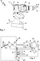
- a hand-held power tool 10 has a housing 11, in the interior of which a drive train 20, 320 is arranged.
- the hand-held power tool 10 is, for example, a screwdriver, drill or both.
- the housing 11 may be conveniently grasped at a handle portion 12 by an operator.
- an upper housing portion 13 which extends like a gun-like angle to the handle portion 12, the drive train 20, 320 is added.
- a hand-held power tool according to the invention can be network-connected, i.
- it can be connected to an electrical supply network or is a battery-powered machine, ie represents a mobile device.
- a switch 15 is provided, with which a drive motor 16 of the hand-held power tool 10 can be turned on or off. Furthermore, it is conceivable to set a speed of the manual power tool 10 with the switch 12.
- a tool holder 18 for receiving a tool 19 is provided, for example, a plug-in receptacle, a chuck or the like.
- the tool 19 is, for example, a drill, a screwdriver bit or the like.
- the hand-held machine tool according to the invention as a milling machine, grinding or polishing machine is of course another useful tool, for example a polishing tool, grinding tool or milling tool or the like.
- the drive motor 16 drives the tool holder 18 via a gear 30. Between the gear 30 and the tool holder 18, a striking mechanism 21 may be connected, so that with the hand-held machine tool 10 even a hammering operation, for example for drilling holes, is possible.
- the drive motor 16, the transmission 30 and the optional hammer mechanism 21 form the drive train 20.
- a transmission 330 is provided instead of the transmission 30.
- the drive motor 16 drives the transmission 30, 330 on the basis of its motor shaft 22.
- the transmission 30 has a switching stage 31 with switchable first and second gear stages 41 and 42.
- the switching stage 31 is followed by a translation stage 32, which further reduces, for example, an output speed of the switching stage 31.
- the translation stage 32 may be, for example, a reduction stage.
- the transmission 30 is designed, for example, as a planetary gear.
- the transmission 30 can be driven via a drive shaft, for example the motor shaft 22.
- a drive wheel 33 is arranged on the motor shaft 22.
- the drive wheel 33 drives the switching stage 31.
- the drive wheel 33 forms a transmission drive 25.
- the drive wheel 33 is a sun gear 34 that drives transfer wheels 35.
- the transmission wheels 35 are, for example, planet wheels 36, which are rotatably mounted on a planetary carrier 37 on planetary axles 40.
- the planetary axles 40 are, for example, rotatable on the planet carrier 37 or the planetary gears 36 rotatably mounted on the planetary axles 40. It can, for example, sliding bearings, ball bearings or needle roller bearings or other bearings between the planetary gears 36 and the planetary axles 40 or the planetary axles 40 and the planet carrier 37 may be provided.
- the planet gears 36 mesh with a first pitch circle diameter 38 with the drive wheel 33rd
- another, second pitch circle diameter 39 of the planet gears 36 is smaller than the pitch circle diameter 38, which contributes to a gear ratio.
- the planet gears 36 mesh with a ring gear 45 and a sun gear 46.
- the ring gear 45 is disposed radially outwardly with respect to the planetary gears 36 and surrounds them annularly.
- the sun gear 46 is provided in the center of the planet gears 36, so to speak.
- the ring gear 45 is assigned to the first gear stage 41 and the sun gear 46 to the second gear stage 42.
- the ring gear 45 forms a blocking gear element 43, the sun gear 46 a blocking gear element 44.
- a respective blocking gear element 43 or 44 is blocked by locking devices 61 or 62 of a switching arrangement 60, it forms a support element for the transmission wheels 35, in the present case the planetary gears 36.
- the respectively locked blocking transmission element 43 or 44 switches, as it were, the respective first and second gear stages 41, 42 active.
- a ratchet gear member 43, 44 is not locked by the associated locking means 61, 62, it can rotate freely so that it does not provide support for the transmission wheels 35.
- An unlocked blocking gear element 43, 44 switches the associated first and second gear stage 41, 42 inactive. Under active and inactive is to be understood that a torque can be transmitted from the drive side to the output side.
- the blocking gear element 43 is arranged with its radially outer circumference, so to speak, directly on or next to the blocking device 61.
- This also has a radially outer support region, namely in the form of a Abstützrads 47 which is connected to the sun gear 46 or in one piece.
- the support wheel 47 is connected to the sun gear 46 through a connecting disc and / or spokes 47A.
- the Abstützrad 46 and the lock gear member 43, so the ring gear 45, have the same radial outer circumferences.
- a passage opening 48 is provided, through which the motor shaft 22 is connected to the drive wheel 33.
- the switching stage 31 drives via a driven gear 49 to the translation stage 32.
- the translation stage 32 is configured as a planetary stage 50.
- the output gear 49 is driven by the planet carrier 37 or in one piece with this.
- the output gear 49 protrudes in front of the planet carrier 37.
- the planet gears 51 are arranged in the interior of a ring gear 54, which is fixed relative to the housing 11 of the hand-held power tool 10 or a transmission housing 90 of the transmission 30.
- the ring gear 54 is fixed in place, for example, on a housing portion 93 of the gear housing 90. Consequently, therefore, the planet gears 51 roll on the inner circumference of the ring gear 54 from.
- the planetary gears 51 are rotatably supported, for example, on the planetary axles 53.
- the planetary axles 53 have an additional function, namely by coupling the planetary carrier 52 with an output shaft 54 of the transmission 30 in a torque-proof manner.
- the planetary shafts 53 protrude on opposite sides in front of the planetary carrier 52, on the one hand rotatably supporting the planet gears 51, on the other hand coupling a transmission element 56 for the output shaft 55 rotatably or are firmly connected thereto.
- the transmission element 56 receives, for example, a shaft portion 57 of the output shaft 55 or is fixedly connected to this shaft portion 57.
- the output shaft 55 is rotatably supported, for example, on bearings 59 on a portion 91 of the transmission housing 90.
- a tool section 58 which has the tool holder 58 on its end face, protrudes in front of a front side 92 of the gear housing 90.
- the transmission housing 90 is closed by a cover 95.
- the lid 95 has a passage opening for the motor shaft 22 or other drive shaft.
- the transmission 30 can be advantageously encapsulated, may have seals or the like, for example, at an opening on the front side 92, where the output shaft 55, the transmission housing 90 penetrates.
- the two locking devices 61, 62 are each designed as freewheels.
- the power flow or the torque transmission from the transmission drive 25, for example, from the drive wheel 33 or the motor shaft 22, to a transmission output 25, for example, the output gear 49 or the output shaft 58 of the transmission 30 can by a simple reversal of direction of the drive motor 16 between the Gear stage 41 and the gear stage 42 are switched.
- the direction of rotation of the drive motor 16 is quickly switchable, in particular because the drive motor 16 in an advantageous embodiment of the invention is a so-called brushless motor, eg electronically commutated motor.
- the locking device 62 releases the lock gear member 44, so that no power flow is possible through the second gear 44.
- the sun gear 46 turns free.
- the other inhibitor 61 then operates, i. It locks the associated support member or blocking gear element 43, namely the ring gear 45.
- the transmission wheels 35 in this case the planetary gears 36, at the stationary with respect to the gear housing 90 ring gear 45 roll and thus a power flow or torque transmission from the transmission drive 25 for Gearbox output 26 allow.
- the gear stages 41, 42 each provide a torque ratio and speed change between on the one hand the transmission drive 25 and on the other hand the transmission output 26 ready.
- the operator can actively switch the direction of rotation of the drive motor 16 for this purpose.
- a controller 80 of the Manual machine tool 10 causes the reversal of rotation automatically, for example, as a function of torque and / or speed of the drive motor 16.
- the controller 80 could be an analog controller that monitors its torque output with a simple current monitoring, for example, of the drive current leading to the drive motor 16, thus switching the direction of rotation accordingly.
- a digital control for example by means of corresponding digital circuits, in particular a microprocessor 81.
- This operates on the basis of a software program 86 which is stored in a memory 82 which the processor 81 can read.
- the processor 81 On the basis of the software program 86 or another software program, the processor 81, for example, an output stage 83 to drive the drive motor 16 to control.
- the output stage 83 contains, for example, power electronics.
- the controller 80 receives signals, for example, from the switch 15 or a Drehbaumeinstellelement 23, with which a speed of the drive motor 16 can be predetermined by the operator.
- the controller 80 changes the direction of rotation of the drive motor 16, for example, so that the transmission 30 switches back, for example, from the second gear stage to the first gear stage.
- the controller 80 reversely changes the rotational direction of the drive motor 16, so that the transmission 30 shifts from the first gear stage to the second gear stage, so that the drive motor 16 can rotate at a lower speed.
- the locking devices 61, 62 are, so to speak, sandwiched between the blocking gear elements 43 and 44 on the one hand and a housing section 94 of the gear housing 90. Thus, so the lock means 61, 62 so to speak radially outer components of the transmission 30. Because the locking means 61, 62 are arranged radially outward, they are also easy to intervene outside, so for example for a changeover of the respective reverse direction accessible.
- the two locking devices 61, 62 designed as freewheels can be shifted in relation to their locking direction and freewheeling direction.
- the locking devices 61, 62 include a common support ring 63, which could be described as a freewheel ring.
- each locking device 61, 62 it would also be readily possible for each locking device 61, 62 to be designed as a separate freewheel device, i. that there are no common components.
- the support ring 63 is fixed relative to the transmission housing 90.
- support body 64 in particular bolts or the like, between the inner circumference of the gear housing 90, so the housing portion 94, and the outer periphery of the support ring 63 is positively inserted and hold the two components form-fitting together.
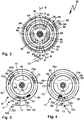
- the support ring 63 has at its inner periphery rotationally offset several, for example three, freewheel recesses 65, in each of which a locking element 68 or 69, in particular a ball, roller or pin, a respective locking device 61 is 62 out.
- the locking devices 61 have mutually separate locking elements 68, 69, so that they can have opposite direction of freewheeling in and locking directions.
- the blocking elements 68, 69 are mounted between the outer peripheries of the locking gear elements 43, 44 and the inner circumference of the support ring 63 in the region of the respective freewheel recesses 65.
- the locking elements 68, 69 with respect to a rotational axis D, to which the locking gear elements 45, 46, namely the ring gear 45 and the combination of sun gear 46 and Abstützrad 47th rotate, on the outer circumference of the respective blocking gear element 43, 44 are moved, namely in the region of the freewheel recesses 65 in or out of these, in clamping slope or constrictions 66, 67th
- the blocking elements 68, 69 of a locking device 61 or 62 are in the freewheel recesses 65, the respective locking device 61 or 62 is in free-running. However, if the locking elements 68, 69 are moved in the direction of the clamping slope in or constrictions 66 or 67, the locking device 61, 62 is locked. The associated blocking gear element 43, 44 is then blocked by the arranged on its outer circumference locking elements 68, 69, which are located in one of the clamping bevels 66 or 67 and supported on the support ring 63, with respect to a rotation about the rotation axis D, so that the blocking gear member 43, 44 can serve to support the planet gears 36 and thus the respective gear stage 41 or 42 is active.
- the blocking direction or free-wheeling direction of a respective locking device 61, 62 is switchable.
- a switching device 70 is provided, which is easily actuated by a single, manual actuator 71 by an operator.
- the actuating element 71 is configured, for example, as a projection in front of a switching element 72 designed as a ring, for example, which is rotatable about the axis of rotation D.
- pin-like guide elements 73 which are also referred to below with 73a and 73b, in the direction of the locking elements 68, 69, wherein a respective locking element 68, 69 is arranged between pairs opposite guide elements 73.
- the locking elements 69 are adjusted in the direction of the clamping bevels 66, so that the locking device 61 in a rotational direction D1 blocks or blocks the support member or locking gear member 44.
- the guide elements 73b hold the locking elements 69 in the freewheel recesses 65.
- the direction of rotation D2 thus corresponds to a freewheeling direction F1, the direction of rotation D1 a reverse direction S1 of the locking device 62 in the position according to Figures 3 or 4 ,
- the switching device 70 is provided with a fixing device 100.
- the fixing device 100 comprises a clamping device 101.
- the clamping device 101 has a clamping bevel 102, as well as a clamping bevel 103, against which the actuating element 71 in the switching position T1 in accordance FIGS. 3 and 4 each runs up.
- a rotation of the switching element 72 counterclockwise not shown in detail
- a switching position T2 can be reached, in which the support wheel 47 and the sun gear 46 rotate in the direction of rotation D1 and can not rotate in the direction of rotation D2, that is locked.
- a clamping slope in the form of the clamping slope 103 is provided for this switching position T2, the only by a corresponding position of the actuating element 71 in FIG. 4 is indicated.
- each have a spring element 75 is provided between the guide elements 73 and the locking elements 68, 69 each have a spring element 75 is provided.
- the spring elements 75 bias the locking elements 68, 69 in the direction of the locking position, i. in the direction of the clamping bevels 66, 67 into it.
- the locking elements 68, 69 are already loaded in the direction of the locking position, so that the blocking function or from supporting function of the locking gear elements 43, 44 is available as directly as possible.
- the blocking elements 68, 69 are advantageously movably decoupled from each other.
- a decoupling ring 74 between the locking elements 68, 69 is arranged.
- the locking direction and the freewheeling direction of the locking devices 61, 62 can be reversed in opposite directions, namely by the switching device 70. Namely, when the actuating element 71 is actuated about the axis of rotation D, make the guide elements 73 this rotational movement, so that they starting from a middle position about accordingly FIG. 2 in relation to the rotational axis D rotationally offset position, for example, a switching position T1 for clockwise or a switching position T2 for left-hand rotation of the tool holder 18 (facing the front side according to FIGS. 3, 4 ) are adjustable.
- the blocking direction S1 and the freewheeling direction F1 can be reversed in opposite directions.
- the controller 80 adjusts the direction of rotation of the drive motor 16 as a function of the position of the switching device 70 for clockwise or anti-clockwise rotation so that it switches to clockwise rotation or vice versa in a gear stage occupied before switching the direction of rotation 41 or 42 starts.
- a sensor 85 is arranged on the switching device 70 in order to detect their respective switching position.
- the sensor 85 is, for example, an electrical contact, a non-contact contact or the like.
- an inductive, optical or capacitive measuring element may be provided as a sensor, but also an electrical contact switch or the like.
- the first gear stage 41 is a negative gear
- the second gear 42 is a plus gear, so that by a simple reversal of the drive motor 16 in the transmission 30, the gear stages 41 and 42 are switchable, but so that no reversal of rotation is connected to the transmission output 26.
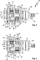
- the powertrain 320 includes a transmission 330, which is constructed with respect to a switching stage 331 similar to the transmission 30 and its switching stage 31. However, different is the operating concept (with a switching device 370) in a switching arrangement 360, which corresponds functionally to the switching arrangement 60 , as well as the output side of the gearbox 330, where instead of a simple Planet stage or a simple reduction gear as in the embodiment according to FIGS. 5 and 6 a switchable gear assembly 350 is provided. As far as the same or similar components in the embodiment according to FIGS. 5 and 6 and the other embodiment according to FIGS. 8 and 9 are present, they are provided with the same reference numerals, but to illustrate differences in part with increased by 300 reference numerals.
- the switching stage 331 drives with its transmission output 25 to a switching stage 332, which can work as a reduction stage in terms of speed reduction, but does not have to.
- the drive motor 16 drives a drive wheel 333 via the motor shaft 22.
- a receptacle 333a is provided on the drive wheel 333 or a shaft element connected thereto for receiving and rotationally fixed coupling of the motor shaft 22.
- the drive wheel 333 forms a sun gear 334 which meshes with planet gears 336.
- the planetary gears 336 advantageously form transmission wheels 35.
- the planet gears 336 are rotatably mounted on a planet carrier 337.
- planetary axes 40 are rotatably mounted on the planet carrier 37 or the planet carrier 336 are rotatably mounted on the planetary axles 40.
- the planet gears 336 have different pitch circle diameters 38, 39 as the planetary gears 36. With the pitch circle diameter 38, the planet gears 336 mesh with the sun gear 334, while the smaller pitch circle diameter 39 provides that the planet gears 336 engage a ring gear 345, thus comb or the ring gear 345 can take-along.
- the switching stage 331 has a first gear stage 341 (corresponding to the gear stage 41) and a second gear stage 342 (corresponding to the gear stage 42), between which the switching stage 331 is switchable based on a reversal of the direction of rotation of the drive motor 16.
- the planet gears 336 are so to speak radially inwardly supported, namely can roll on a sun gear 346, which forms part of a blocking gear member 344.
- the blocking gear element 344 corresponds to the blocking gear element 44 and has a passage opening 48 for the motor shaft 22.
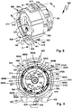
- the switching arrangement 360 comprises a blocking device 361 for blocking or releasing the blocking gear element 343 and a blocking device 362 for blocking or releasing the blocking gear element 344
- FIG. 11 schematically illustrated locking elements 368, 369 are based on a support ring or freewheel ring 363 from (similar to the components 68, 69 and 63) and are preferably by in FIG. 10 visible spring elements 375 (corresponding to the spring elements 75) loaded.
- the support ring 363 is fixed relative to the transmission housing 390.
- supporting body 364 in particular supporting projections, between the inner circumference of the gear housing 390, in particular the housing portion 394, and the outer periphery of the support ring 363 provided to hold the two components form-fitting together.
- the support bodies 364 are, for example, support projections which engage in corresponding support receptacles 364A of the transmission housing 390.
- the actuator 371 protrudes radially outward in front of a transmission housing 390 of the transmission 330, so it can be easily grasped by the operator.
- the actuator 371 is rotatably mounted on the support ring or freewheel ring 363 or passes through this.
- the actuator 371 is provided on a housing portion 394 of the gear housing 390, in which the switching stage 331 is received.
- the actuator 371 is rotatably connected to the switching element 372.
- a portion 374 of the example rod-shaped or annular actuator 371 is coupled to the switching element 372.
- the switching element 372 is, for example similar to the switching element 72 annular. In contrast to the switching element 72, however, the switching element 372 is arranged between the gear stages 341, 342 and between the blocking gear elements 343, 344. For example, a protrusion 372a engages an intermediate portion or space between the ring gear 345 and the support gear 347 of the ratchet gear member 344.
- the switching device 370 can also be fixed by a fixing device 300, for example a fixing device in the manner of the fixing device 100.
- a fixing device 300 may be provided with a locking device 301.
- a locking element 301 for example a fork, a pin or the like, is displaceably mounted on the transmission housing 390 or housing 11.
- the locking element 301 can be brought out of engagement with the actuating element 371 in an unlocking position E, in a locking position V in engagement with the actuating element 371 (FIG. FIG. 11 ).
- the actuating element 371 In the locking position V, the actuating element 371 is no longer rotatable, for example with respect to the axis of rotation D, so that the switching element 362 remains in the respective switching position T1 or T2.
- the transmission 390 is also provided on its side facing the drive motor 16 by a cover, here a cover 395. locked. On a side facing away from the cover 395, next to the housing portion 394, there is a further housing portion 393, which receives the gear assembly 350, that is, the switching stage 332.
- the housing section 393 is closed by a cover 391, on whose front side or front side 392 the output shaft 55 is coupled to the tool holder 18.
- the tool shaft 18 is driven by the gear stage or shift stage 332, which in turn is in turn coupled to the transmission output 26 of the switching stage 31.
- the gear output 26 includes a driven gear 349, which is for example fixedly connected to the planet carrier 337, for example, is integral therewith.
- the output gear 349 forms a sun gear with which planet gears 351 of the gear assembly 350 mesh.
- the planet gears 351 are rotatable with respect to a planetary carrier 352, for example, by being rotatably supported on planetary axles 353 or by the planetary axles 353 being rotatably supported on planetary carriers 352.
- the gear assembly 350 couples a ratchet wheel 354, such as a ring gear, the gear assembly 350, the planetary gears 351 rotatably connected to the planet carrier 337.
- the planet carrier 337 has, for example on its outer periphery a toothing 337a, which can engage with internal teeth of the ratchet wheel 354. Also in engagement with this gearing or lying next to this gearing is a respective planetary gear 351st
- the planet gears 351 mesh with the internal teeth of the ratchet wheel 354, so roll on this.
- the ratchet wheel 354 in turn is rotationally fixed with respect to the transmission housing, for example by means of an external toothing 354a of the ratchet wheel 354, which is in engagement with an internal toothing 354b on the housing 390, for example the cover 391.
- the internal toothing 354b is radially inward, the external toothing 354a radially outward.
- the shiftable transmission assembly 350 can be manually switched, for example, by an actuating element 310 which is displaceably mounted in or on a receptacle 311 of the transmission housing 390.
- the actuating element 310 is coupled in terms of movement by means of a coupling element 312 to the switching wheel 354, but could also be fixedly arranged on the switching wheel 354.
- the coupling element 312 includes, for example, pins, brackets or the like other components, which allows a power transmission from an outside of the transmission case 390 in the interior thereof, where the switching wheel 354 is arranged.
- the receptacle 311 forms a sliding bearing or a sliding receptacle, in which the actuating element 310 is received linearly displaceable.
- the actuating element 310 is coupled in motion or in one piece with a manually engageable actuating handle 313, for example a ring or slider.
- the actuating handle 313 projects, for example, in front of the housing 11 of the hand-held power tool 10, so it is easy to grasp.
- a concept for switching the gear assembly 350 is an actuator 387, for example, an electromagnet, an electric motor or the like (a pneumatic drive is also possible).
- the actuator 387 is configured and provided for an adjustment of the switching wheel 354, that is to say a switching element of the gear arrangement 350, between at least two switching positions.
- the actuator 387, the ratchet 354 between the switch positions according to FIGS. 8 and 9 adjust back and forth.
- the actuator 387 is driven, for example via an electrical switch 24a on the housing 11 of the hand-held machine tool 10.
- the actuator 387 is housed protected in the interior of the transmission housing 390.
- the representation of the actuator 387 is to be understood as an example.
- the controller 80 is preferably designed to control the activation of the actuator 387.
- it has a switching output 388 for switching the actuator 387.
- the controller 80 can thus automatically switch the gear stage or shift stage 331, for example, and advantageously also the shiftable gear arrangement 350 or the shift stage 332.
- the gear stage or shift stage 331 for example, and advantageously also the shiftable gear arrangement 350 or the shift stage 332.
- sensors can also be provided on the output area, which interacts with the controller 80.
- a sensor 87 for detecting rotational speed and / or torque and / or rotational direction or the like, for example a tachometer, a torque detection, may be provided on the tool shaft or output shaft 55.
- a sensor 88 for example, an optical sensor, a Hall sensor or the like, the drive motor 16, for example, detect its torque and / or direction and / or speed.
- a sensor 89 in particular for speed detection and / or torque detection and / or rotational direction detection, may be provided at the input of the transmission 30, 330, for example on the motor shaft 22.
- the sensors 87, 88, 89 report their respective sensor signals via the input interface 84 of the controller 80, which adjusts, for example, the speed and / or direction of rotation of the drive motor 16 by means of its software program 86 in order to switch the transmission 30, 330 in this way. Based on the signals of the sensors 87,1888, 89, the controller 80 but the actuator 387 control.
- the sensor signals of the sensors 87, 89, 88 can also be used to control the drive motor 16 and / or to control and in particular also the transmission 330, in particular its switching stage 332, to switch.
- an operator can, for example, specify a desired maximum speed or setpoint speed SD of the output shaft 55.
- a desired maximum speed or setpoint speed SD of the output shaft 55 For example, the operator can specify a maximum speed of 2000 to 4000 rpm for a drilling operation, and a maximum speed of 500 to 2000 rpm for a screwing operation.
- an optional torque setting element 24 for example a rotatable adjusting element, a slide or the like
- the operator can, for example, specify a desired maximum torque or setpoint torque SM on the output shaft 55.
- a desired maximum torque or setpoint torque SM on the output shaft 55.
- a speed control or torque control may be advantageous, for example, in a milling cutter or saw.
- a touch-sensitive display can be provided, which displays the set values SM and / or SD.
- a control module 86a of the software program 86 can, for example, based on the maximum values or target values SM and / or SD and the feedback of the set values, namely the actual values, the sensors 87, 88, 89 supply, the drive motor 16 and / or drive the power amplifier 83 and / or rules. Furthermore, the control module 86a can also control the actuator 387 in accordance with these values via the switching output 388 in accordance with the switching of the gear stage 332.
- the controller 80 controls the actuator 387 to shift the transmission 332 from the shift position in which the shift 332 does not realize speed reduction relative to the transmission output 26 (FIG. FIG. 10 ), in the switching position, in which the gear stage 332 acts as a reduction gear ( FIG. 11 ), ie the position at which the planet gears 351 roll in the ring gear 354.
- the planetary axes 353 or 53 may be part of a spindle stop, i. that a rotational blocking on the output side of the gear 30, 330 readily at this point is feasible.
- the switching element 372 is sandwiched between the locking devices 61, 62.
- An alternative operating concept or switching concept is in the FIGS. 8, 9 . 12, 13 for the transmission 330.
- FIG. 9 designed as a freewheel device or freewheel blocking device 361 shown in somewhat greater detail.
- the switching element 472 is designed, for example, as a disk body.
- the switching element 472 of the switching device 470 is rotatably mounted about the rotational axis D in the gear housing 330.
- 390 rolling elements 476 are provided between the switching element 472 and the transmission housing, in particular balls.
- a three-point bearing that is, for example, at an angle of 120 ° each have a rolling element 476 is provided between the switching element 472 and the inner circumference of the gear housing 390.
- the rolling elements 476 pockets or the like other bearing receptacles 477 provided on the gear housing 390 or 472 as in the embodiment of the switching element.
- the switching element 472 are guide elements 373 parallel to the rotation axis D in recesses 363A between the support ring 363 and mounted in the support ring 363 locking gear member 344.
- clamping bevels 366, 367 provided in the recess 363A protrusions.
- a blocking element 369A and 369B is arranged in each case.
- the locking elements 369 A, 369 B are held by the guide members 373 close to the projections or at the clamping slopes 366, 367.
- the guide members 373 project into the recesses 363A, for example, in the manner of rods or guide projections. Since the recesses 363A are coaxial with one another, a respective guide element 373 can pass through the recesses 363A of both locking devices 361, 362. Thus, with a single switching element 472, both the locking device 361 and the locking device 362 can be switched simultaneously in terms of their locking direction and freewheeling direction.
- the guide elements 373 are arranged between a respective blocking element 369A, 369B.
- a respective guide element 373 acts directly on a respective blocking element 369A or 369B in the direction of the release direction of rotation, see, for example, a detail section J in FIG FIG. 12 whereby the blocking element 369 B is held in a detailed section J away from the clamping bevel 367 and in the freewheel recess 365, so that the blocking gear element 344 can rotate freely in the direction of rotation D 2, for example.
- the other blocking element 369A is, as it were, acted upon indirectly by the adjacent guide element 373A in the direction of the blocking position, ie in the direction of the clamping bevel 367, namely by means of a spring element 375.
- the adjacent guide element 373B acts on the locking element 369B visible in the detail section J in the direction of the clamping bevel 366.
- the spring elements 373 comprise actuating bodies 375A, which are mounted displaceably relative to one another. Disposed between the actuators 375A is a spring 375B that separates the two actuators 375A in a sense acted upon.
- the actuators 375A are L-shaped, with the short L-leg acting on a locking member 369A or 369B, for example.
- the spring 375B for example a coil spring, is guided between the actuators 375A.
- a guide pin or guide projection extending, for example, between or formed on the actuators 375A extends through an internal space of a respective spring 375B.
- the spring elements 375 form a total of a spring assembly 375C.
- the arrangement when freewheeling or the locking device 361, 362 made such that between the locking elements 369, the guide elements 373 and the spring elements 375 little movement play exists, ie that the aforementioned components are annularly arranged within the recess 363A play with little effort.
- a fast, efficient switching of the directions of rotation at the output of the transmission 330 can be effected when the blocking directions of the locking devices 361, 362 are switched as explained below.
- the so-called play-free concept between the locking elements 368, 369, the guide elements 373 and the spring elements 375 preferably provides that a guide member 373 via a locking element 369A or 369B, which is held in each case in the region of a freewheel recess 365, the spring member 375 charged, which in turn again resiliently another locking element 369 A, 369 B is supported.
- each of the guide members 373 in the clockwise direction or in the rotational direction D1 supports a blocking element 369B such that it is held in the freewheel recess 365.
- This respective blocking element 369A acts on the spring element 375 adjacent in the direction of rotation D1, which in turn holds a blocking element 369A in the region of the clamping slope 367.
- the locking elements 369A can immediately abut the clamping slopes 367 and provide deadlock.
- this functionality also applies to the locking device 361, where the locking elements 368 are correspondingly arranged relative to the guide elements 373 and the spring elements 375 and supported by these in each case.
- the locking device 362 in this case a freewheel, set in a reverse direction S1 (the blocking gear element 344 can rotate in the direction of rotation D2, not in the direction of rotation D1), in the switching position T2 in a reverse direction S2, in which Locking gear element 344 can rotate in the direction of rotation D1 and is locked in the direction of rotation D2.
- the locking device 361 the blocking directions in the switching positions T2 and T1 are provided in relation to the locking device 362 opposite direction of rotation.
- a manual actuator 420 is configured, for example, as a slider.
- the actuating element 420 is displaceably mounted on a sliding guide 424 with respect to the housing 11.
- a respective longitudinal end position of the actuating element 420 with respect to a sliding axis or adjusting axis along the sliding guide 424 is respectively an actuating arm 421 or 422 with its respective operating portion 423 in front of the housing 11 before or at least before the housing 11 before than the other actuating arm.
- the operator has a visually easily recognizable signal, which shift position or switching position, the switching device 470 occupies and thus also with which direction of rotation the gear 330, the tool 19 drives.
- a holder 426 for a sensor guard 425 for example, a permanent magnet
- sensor 85 for example an inductive sensor, Hall sensor, reed contact or similar other contactlessly actuatable sensor, can be actuated, so that in this way controller 80 learns the respective switching position of switching device 470 and drive motor 16 in the sense of drives appropriate direction of rotation. This has already been described in principle.
- a toothed gear is present between the actuating element 420 and the switching element 472, for example, a toothed gear is present.
- a toothing which meshes with a toothed rack or a toothed rack section on the switching element 472, could be provided on the radially outer circumference of the outer side round or a roller element representing switching element 472.
- a transmission gear 430 which includes a lever mechanism 431.
- the lever mechanism 431 includes, for example, a rocker arm as a transmission element 421, with which a sliding operation or linear adjustment of the actuating element 420 can be converted into a rotational movement of the switching element 472.
- the transmission gear 430 simultaneously forms a deflection gear, which converts a linear movement into a rotational movement.
- the transmission element 471 engages with a drive arm 432 in a recess 327 of the actuating element 420.
- the transmission element 471 is mounted on a bearing axis 434 on the switching element 472 pivotable or tiltable.
- a fixing device 400 is realized in connection with the rocker arm concept or the transfer element 471.
- the fixing device 400 is suitable for the bistable fixing of the locking devices 461, 462 in the respective switching positions T1 and T2.
- the fixing device 400 has a latching device 401 or forms a latching device 401.
- the fixing device 400 has a latching element 402, which is displaceably mounted in a bearing or a bearing receptacle 403 on the switching element 472.
- An actuating projection of the locking element 402 presses on an end face of the transmission element 471, specifically the output arm 433.
- the latching force or actuating force required for this purpose is provided by a spring arrangement 404.
- the spring assembly 404 has springs 405.
- the spring assembly 404 is supported in a chamber 406 on the switching element 472 and acts on the locking element 402, which in turn, the rocker arm or the transmission element 472 loaded in its respective Schwenkendwolfen associated with the switching positions T1 and T2.
- the output arm 433 is provided with a rounded end 436 at the end, so that the actuating arm of the latching element 402 slides along the rounding 463.
- the latching element 402 thus loads the transmission element 472 in the direction of its pivot end positions, so that the transmission element 471 is, as it were, forcibly loaded in its respective pivoting end positions.
- a spring force of the spring assembly 404 is designed so that it exceeds the sum of all the forces of the spring elements 375.
- a locking device 442 provided instead of the latching device 401 or in addition to the latching device 401 can provide that, for example, a latch 440 can be brought into a recess 441 on the actuating element 420.
- a lock can be realized.
- the locking element 440 for example, a linearly displaceably mounted on the housing slide 11 or bolt, thus providing additional security.
- the spring force of the spring assembly 404 could also be designed smaller.
- a fixing device is also useful in the case of a motor drive for a switching device.
- a motor drive 429 for example an electromagnetic drive, a coil arrangement or the like, is provided for driving the actuating element 420 and / or the switching device 470 between the switching positions T1 and T2.
- the motor drive 429 is, for example, an actuating projection 428 which projects from the actuating element 420.
- the drive 429 must be energized only briefly to switch between the switching positions T1 and T2. Then, the switching device 470 is held by, for example, the fixing device 400 in the respective switching position T1 or T2.
- a fixing device 500 ( FIGS. 14, 15 ) provides, for example, a latching concept, which corresponds to a latching element 502 on an actuating element 520, which in principle corresponds to the actuating element 420.
- a latching element 502 of a latching device 501 is arranged on the actuating element 520, which is motion-coupled to the transmission element 471 in the manner already described.
- the latching element 502 has a latching arm 503, on which a latching projection 504 is provided.
- the locking projection 504 slides along a detent gate 505, which is stationary with respect to the housing 11 of the power tool 10 or the gear housing 390.
- the detent gate 505 has, for example, inclined surfaces 506, 507, which are arranged on a gate body 508 and are provided on mutually opposite sides of a detent projection 509.
- the latching projection 504 is positioned, for example, on the inclined surface 507, in the switching position T2 on the inclined surface 506.
- the latching element or latching projection 504 thus comes to lie in the switching positions T1, T2 respectively on an inclined surface 506 or 507 and must be assigned via the resistance of the latching projection 509 between the switching positions T1 and T2 Positions with respect to the locking projection 509 are adjusted. Consequently, the latching device 501 engages laterally next to the latching projection 509 on one of the inclined surfaces 506 or 507 with respect to the switch positions T1, T2.
- a spring force of the latching arm 503 is advantageously designed so that it can support the restoring moments or reaction moments of the spring elements 375.
- An additional or alternative concept additionally provides for a jamming of the actuating element 520.
- the actuating element 520 respectively run on clamping bevels 510, 511 in the switching positions T1 and T2 associated longitudinal end positions, in particular with the operating portions 423.
- a clamping bevel in the area between the actuating portions 423 on Betuschistselement 420. Consequently, therefore, the clamping bevels 510, 511 do not necessarily have to act on the actuating sections 423 or be arranged along the outside.
- a corresponding arrangement of clamping bevels in the middle section of the actuating element 520 could look similar to the arrangement of the locking in the fixing device 600 according to FIG FIGS. 16, 17 ,
- a locking device 601 forms a fixing device 600.
- the fixing device 600 cooperates with an actuating element 620, which in itself corresponds to the actuating element 520 or 420, ie in principle serves as an actuating element for a rocker armature or transmission 430.
- latching with, for example, the spring-loaded latching element 402 is optionally possible, but not absolutely necessary.
- the locking element 402 may be fixed in place by a fixing body 407.
- a stationary driving recess 435 could also be provided, that is, for example, that the output arm 433 is unloaded from the front side and only exerts a torque about the axis of rotation D.
- a spring arrangement is provided in the manner of the spring assembly 404, so that an additional fixing force or bistable holding force is provided.
- the sum of the restoring forces the fixing forces of this fixing device with the spring arrangement 404 (instead of the fixing body 407) and the respective latching device 501 or the locking device 601 of the fixing device 600 described below is advantageously greater than the sum of all the reaction forces by the spring elements 375.
- the latching device 601 comprises a latching element 602 provided fixedly with respect to the housing 11 or the gear housing 390.
- the latching element 602 comprises, for example, a spring element which projects with a latching projection 604 in the direction of the actuating element 620.
- the actuating element 620 has the switching positions T1 and T2 associated with or suitably positioned for latching receptacles 605, 606, for example, in the section between the actuating portions 423.
- the latching projection 604 engages in one of the two latching receptacles 605 or 606 in the sliding positions of the actuating element 620, the Switch positions T1 or T2 correspond.
- An additional or alternative fixing effect may be a fixing device 700 with a magnet arrangement 701.
- magnetic elements 703, 704 are provided on the actuating element or slide 620, in particular in the region of the actuating sections 423. Opposed thereto are further magnetic elements 702, 704 which attract the magnetic elements 703, 705.
- the actuator 620 when the actuator 620 is in a respective end position corresponding to one of the switch positions T1 or T2, for example, as in FIG. 16 represent the magnetic elements 704, 705, while the distance between the magnetic elements 702 and 703 is greater, so there is a lower attraction or holding force is provided. This allows a bistable position.
- the magnetic elements 702-704 or elsewhere could be arranged.
- the magnetic elements 702-704 are, for example, permanent magnets or combinations of permanent magnet and ferromagnetic element.
- ferromagnetic region can be provided on the outside of the housing 11, which interact with the permanent magnetic magnet elements 703, 705 in the actuating element 620.
Landscapes
- Engineering & Computer Science (AREA)
- Mechanical Engineering (AREA)
- Structure Of Transmissions (AREA)
- Portable Power Tools In General (AREA)
Claims (15)
- Machine-outil portative, en particulier visseuse et/ou perceuse, avec un moteur d'entraînement (16) servant à entraîner un entraînement de transmission (25) d'une transmission (30), qui présente une sortie de transmission (26) servant à entraîner un logement d'outil (18) de la machine-outil portative (10) et un premier étage de transmission (41) et un second étage de transmission (42), dans laquelle la transmission présente un premier dispositif de blocage (61) servant à bloquer un élément de transmission, formant un élément de transmission de blocage (43), du premier étage de transmission (41) et un second dispositif de blocage (62) servant à bloquer un élément de transmission, formant un élément de transmission de blocage (46), du second étage de transmission (42), dans laquelle l'étage de transmission transfère avec l'élément de transmission de blocage (43, 44) respectivement bloqué un couple de rotation de l'entraînement de transmission (25) vers la sortie de transmission (26), dans laquelle une direction de rotation du moteur d'entraînement (16) peut être commutée et, en fonction de la direction de rotation du moteur d'entraînement (16), le premier étage de transmission (41) ou le second étage de transmission (42) transfère un couple de rotation de l'entraînement de transmission (25) vers la sortie de transmission (26), dans laquelle les dispositifs de blocage (61, 62) bloquent dans une direction de blocage (S1, S2) l'élément de transmission de blocage (43,46) respectif et le débloquent dans une direction en roue libre, et dans laquelle est prévu un dispositif de commutation (70 ; 470) servant à commuter au moins un des dispositifs de blocage (61, 62) entre une première position de commutation (T1, T2) et une seconde position de commutation (T1, T2), dans lesquelles les directions de blocage (S1, S2) de l'au moins un dispositif de blocage (61, 62) sont opposées l'une à l'autre, caractérisée en ce qu'elle présente un dispositif de fixation (400) servant à fixer l'au moins un dispositif de blocage (61, 62) dans la position de commutation (T1, T2) respective.
- Machine-outil portative selon la revendication 1, caractérisée en ce que le dispositif de fixation (400) est ou comprend un dispositif d'enclenchement (401, 501, 601) et/ou un dispositif de serrage (101) et/ou un ensemble magnétique (701) et/ou un dispositif de verrouillage (301).
- Machine-outil portative selon la revendication 1 ou 2, caractérisée en ce que le dispositif de fixation (400) est configuré pour fixer de manière bistable les dispositifs de blocage (61, 62) dans la position de commutation (T1, T2) respective, dans laquelle le dispositif de fixation (400) contraint avec une force de réglage le dispositif de blocage (61, 62) ou le dispositif de commutation (70 ; 470) depuis au moins une position située entre les positions de commutation (T1, T2) en direction de l'une ou de l'autre position de commutation (T1, T2), et/ou en ce que le dispositif de fixation (400) présente un ensemble de ressorts (404) et/ou un ensemble magnétique (701) servant à fournir une force de réglage servant à ajuster un dispositif de blocage (61, 62) dans la position de commutation (T1, T2) respective et/ou une force de maintien servant à maintenir les dispositifs de blocage (61, 62) dans la position de commutation (T1, T2) respective et/ou en ce que le dispositif de blocage (61, 62), en particulier la roue libre, présente au moins un élément de blocage (69, 369) contraint par un élément de ressort (375 ; 75) en direction de sa position de blocage, en particulier un corps de roulement, ou un ensemble de plusieurs éléments de blocage (69, 369) contraintes en direction de la position de blocage par un ensemble de ressorts (375C).
- Machine-outil portative selon l'une quelconque des revendications précédentes, caractérisée en ce que le dispositif de fixation (400) présente une force de maintien suffisante pour maintenir l'au moins un élément de blocage (69, 369) ou un ensemble de plusieurs éléments de blocage (69, 369) dans la zone de la position de blocage, en particulier pour soutenir au moins un élément de ressort (375) contraignant l'élément de blocage (69, 369) dans la position de blocage ou pour soutenir un ensemble de ressorts (375C), qui contraint plusieurs éléments de blocage (69, 369) dans la position de blocage.
- Machine-outil portative selon l'une quelconque des revendications précédentes, caractérisée en ce que le dispositif de commutation (70 ; 470) présente un élément de commutation (72) de forme annulaire, en particulier en forme de disque, et monté de manière à pouvoir tourner autour d'un axe de rotation, en particulier à la manière d'un palier de roulement ou à l'aide d'éléments de palier de roulement, dont dépasse au moins un élément de guidage (73, 373) et qui vient en prise avec un évidement (363A) du premier dispositif de blocage (61, 62) ou du second dispositif de blocage (61, 62), dans laquelle au moins un élément de blocage (69, 369), en particulier un corps de roulement, est monté de manière mobile entre une position en roue libre débloquant l'élément de transmission de blocage (43, 46) et une position de blocage bloquant l'élément de transmission de blocage (43, 46) pour l'ajustement du dispositif de blocage (61, 62) et l'élément de blocage (69, 369) peut être maintenu par l'au moins un élément de guidage (73, 373) dans une position associée à la position en roue libre, dans laquelle il est prévu de manière avantageuse que soient prévus dans l'évidement (363A) du dispositif de blocage (61, 62) au moins deux éléments de blocage (69, 369), dont au moins un est contraint par l'au moins un élément de guidage (73, 373) dans une position associée à la position en roue libre et un autre est contraint par l'autre élément de guidage (73, 373) dans une position associée à la position de blocage en fonction de la première position de commutation (T1, T2) ou de la seconde position de commutation (T1, T2).
- Machine-outil portative selon l'une quelconque des revendications précédentes ou selon le préambule de la revendication 1, caractérisée en ce qu'une transmission de transfert (430) est disposée entre un élément d'actionnement (420) servant à actionner le dispositif de commutation (70 ; 470) et un élément de commutation (72) agissant sur au moins un dispositif de blocage (61, 62) pour l'ajustement entre la première et la seconde position de commutation (T1, T2) et pouvant être actionné par l'élément d'actionnement (420).
- Machine-outil portative selon la revendication 6, caractérisée en ce que la transmission de transfert (430) provoque une déviation de force entre l'élément d'actionnement (420) et l'élément de commutation (72), et/ou en ce que l'élément d'actionnement (420) est monté de manière mobile linéairement et l'élément de commutation (72) est monté de manière mobile de manière à pouvoir tourner, et/ou en ce que la transmission de transfert (430) comprend une transmission dentée ou une transmission à levier (431), et/ou en ce qu'un levier de basculement est disposé entre l'élément de commutation (72) et l'élément d'actionnement (420), dans laquelle le levier de basculement est contraint par ressort par un ensemble de ressorts le contraignant en particulier côté frontal et/ou soutenu au niveau de l'élément de commutation (72) dans une position associée à la première position de commutation (T1, T2) ou à la seconde position de commutation (T1, T2), et/ou en ce que l'élément d'actionnement (420) est un élément d'actionnement manuel et/ou est configuré pour actionner un capteur ou commutateur relié à une commande du moteur d'entraînement, avec lequel la première position de commutation (T1, T2) ou la seconde position de commutation (T1, T2) peut être signalée à la commande.
- Machine-outil portative selon l'une quelconque des revendications précédentes ou selon le préambule de la revendication 1, caractérisée en ce qu'un élément d'actionnement (420) servant à actionner le dispositif de commutation (70 ; 470) fait saillie du boîtier au niveau de côtés opposés les uns aux autres du boîtier de la machine-outil portative et/ou peut être actionné au niveau de côtés opposés les uns aux autres du boîtier de la machine-outil portative.
- Machine-outil portative selon l'une quelconque des revendications précédentes, caractérisée en ce que le dispositif de commutation (70 ; 470) est configuré pour commuter de manière simultanée ou de manière séquentielle la direction de blocage (S1, S2) du premier dispositif de blocage (61) ou du second dispositif de blocage (62) pour une inversion de direction de rotation de la sortie de transmission (26), et/ou en ce que le dispositif de commutation présente un entraînement motorisé servant à commuter les dispositifs de blocage, et/ou en ce que le dispositif de commutation (70 ; 470) est couplé à une commande (80) du moteur d'entraînement (16) de sorte que la commande (80) commute la direction de rotation du moteur d'entraînement (16) lors de la commutation de la direction de blocage (S1, S2) du premier dispositif de blocage (61) et du second dispositif de blocage (62).
- Machine-outil portative selon l'une quelconque des revendications précédentes, caractérisée en ce que les directions de blocage (S1, S2) du premier dispositif de blocage (61) et du second dispositif de blocage (62) peuvent être commutées de manière simultanée par un élément d'actionnement (71, 171) unique, et/ou en ce que le premier dispositif de blocage (61) et/ou le second dispositif de blocage (62) est une roue libre ou comprend une roue libre, dans laquelle la roue libre forme de manière avantageuse une composante radialement extérieure ou radialement le plus à l'extérieur de la transmission.
- Machine-outil portative selon l'un quelconque des revendications précédentes, caractérisée en ce que le premier dispositif de blocage (61) et le second dispositif de blocage (62) présentent une direction de blocage (S1, S2) dans le même sens ou dans le sens opposé, dans laquelle il est prévu de manière avantageuse que le premier dispositif de blocage (61) et le second dispositif de blocage (62), en particulier la première et la seconde roue libre, soient disposés côte à côte de manière coaxiale, et/ou en ce que les deux dispositifs de blocage (61, 62) ou les deux roues libres forment une composante radialement extérieure ou le plus à l'extérieur de la transmission.
- Machine-outil portative selon l'une quelconque des revendications précédentes, caractérisée en ce que la transmission (30) présente un étage planétaire, dans laquelle des roues planétaires (36) de l'étage planétaire sont montées de manière à pouvoir tourner au niveau d'un support planétaire (37) comportant une sortie, dans laquelle les roues planétaires (36) sont entraînées par une roue d'entraînement, dans laquelle les roues planétaires (36) s'engagent avec une roue solaire de blocage (46) pouvant être bloquée par le premier dispositif de blocage (61) et avec une couronne de blocage (45) pouvant être bloquée par le second dispositif de blocage (62) de sorte que le premier ou le second étage de transmission (42) peut être activé par blocage de la roue solaire de blocage (46) ou de la couronne de blocage (45).
- Machine-outil portative selon l'une quelconque des revendications précédentes, caractérisée en ce qu'au moins un élément de transmission de blocage (43, 44) pouvant être bloqué par un dispositif de blocage respectif est configuré en tant qu'une couronne (45) ou présente une couronne (45), et/ou en ce que les éléments de transmission de blocage (43, 44) présentent des directions de rotations opposées l'une à l'autre quand le premier dispositif de blocage (61) et le second dispositif de blocage (62) débloquent l'élément de transmission de blocage (43, 44) respectif, et/ou en ce que les deux étages de transmission provoquent une modification de vitesse de rotation entre l'entraînement de transmission (25) et la sortie de transmission (26) et un des deux étages de transmission provoque une inversion de direction de rotation entre l'entraînement de transmission (25) et la sortie de transmission (26).
- Machine-outil portative selon l'une quelconque des revendications précédentes, caractérisée en ce que le dispositif de commutation (70 ; 470) est prévu pour commuter les dispositifs de blocage (61, 62) entre la première position de commutation (T1, T2) et la seconde position de commutation (T1, T2) de telle manière que les directions de blocage (S1, S2) du dispositif de blocage (61, 62) respectif sont opposées l'une à l'autre dans les positions de commutation (T1, T2), et en ce que le dispositif de fixation (400) est prévu et configuré pour fixer les dispositifs de blocage (61, 62) dans la position de commutation (T1, T2) respective.
- Machine-outil portative selon l'une quelconque des revendications précédentes, caractérisée en ce que le dispositif de commutation (70) présente un élément de commutation (72), avec lequel le premier dispositif de blocage (61) et/ou le second dispositif de blocage (62) peuvent être commutés et/ou qui présente au moins un élément de guidage (73), dans laquelle l'au moins un élément de guidage (73) est prévu pour maintenir au moins un élément de blocage (68, 69) du premier dispositif de blocage (61) et/ou du second dispositif de blocage (62) dans un creux de roue libre (65) du dispositif de blocage (61, 62) et/ou autorise, dans la première position de commutation (T1), une compression de l'au moins un élément de blocage (68, 69) contre un premier chanfrein de serrage (66) associé à une première direction de blocage et l'empêche contre un second chanfrein de serrage (67) associé à une seconde direction de blocage opposée à la première direction de blocage et empêche, dans la seconde position de commutation (T2), une compression de l'au moins un élément de blocage (68, 69) contre le premier chanfrein de serrage (66) et l'autorise contre le second chanfrein de serrage (67).
Applications Claiming Priority (2)
| Application Number | Priority Date | Filing Date | Title |
|---|---|---|---|
| DE102016124685 | 2016-12-16 | ||
| DE102017100063 | 2017-01-03 |
Publications (2)
| Publication Number | Publication Date |
|---|---|
| EP3335839A1 EP3335839A1 (fr) | 2018-06-20 |
| EP3335839B1 true EP3335839B1 (fr) | 2019-05-01 |
Family
ID=60781551
Family Applications (1)
| Application Number | Title | Priority Date | Filing Date |
|---|---|---|---|
| EP17207416.3A Active EP3335839B1 (fr) | 2016-12-16 | 2017-12-14 | Machine-outil portative |
Country Status (3)
| Country | Link |
|---|---|
| EP (1) | EP3335839B1 (fr) |
| DE (1) | DE102017129988A1 (fr) |
| DK (1) | DK3335839T3 (fr) |
Families Citing this family (1)
| Publication number | Priority date | Publication date | Assignee | Title |
|---|---|---|---|---|
| DE102019216866A1 (de) * | 2019-10-31 | 2021-05-06 | Robert Bosch Gmbh | Handwerkzeugmaschine |
Family Cites Families (3)
| Publication number | Priority date | Publication date | Assignee | Title |
|---|---|---|---|---|
| AU674631B2 (en) * | 1994-08-26 | 1997-01-02 | Matsushita Electric Works Ltd. | Planetary gear transmission system |
| DE102012212032A1 (de) * | 2012-07-10 | 2014-01-16 | Metabowerke Gmbh | Getriebeanordnung |
| DE102015110504A1 (de) * | 2015-06-30 | 2017-01-19 | Festool Gmbh | Hand-Werkzeugmaschine |
-
2017
- 2017-12-14 EP EP17207416.3A patent/EP3335839B1/fr active Active
- 2017-12-14 DK DK17207416.3T patent/DK3335839T3/da active
- 2017-12-14 DE DE102017129988.2A patent/DE102017129988A1/de not_active Withdrawn
Non-Patent Citations (1)
| Title |
|---|
| None * |
Also Published As
| Publication number | Publication date |
|---|---|
| DE102017129988A1 (de) | 2018-06-21 |
| EP3335839A1 (fr) | 2018-06-20 |
| DK3335839T3 (da) | 2019-07-29 |
Similar Documents
| Publication | Publication Date | Title |
|---|---|---|
| EP3317051B1 (fr) | Machine-outil portative | |
| EP2661336B1 (fr) | Transmission à trains épicycloïdaux pour une machine-outil | |
| EP3676054B1 (fr) | Machine-outil portative | |
| DE102004018084B3 (de) | Hammerbohrgerät | |
| EP3676053B1 (fr) | Machine-outil portative | |
| EP1886769B1 (fr) | Machine-outil dotée d'un train épicycloïdal à plusieurs niveaux | |
| DE3234571A1 (de) | Schaltbares drehzahluntersetzungsgetriebe fuer ein rotierendes elektrisches maschinenwerkzeug | |
| WO2000063589A1 (fr) | Dispositif de commande de boite planetaire a deux vitesses | |
| EP2655019A1 (fr) | Machine-outil à main | |
| EP2913159A1 (fr) | Outil électrique à main doté d'un dispositif de verrouillage de broche | |
| EP3676052A1 (fr) | Machine-outil portative | |
| EP2480372B1 (fr) | Dispositif d'entraînement | |
| WO2010034563A1 (fr) | Machine-outil manuelle équipée d'une transmission débrayable | |
| EP1886768B1 (fr) | Machine-outil dotée d'engrenages à plusieurs étapes | |
| EP3335839B1 (fr) | Machine-outil portative | |
| EP2095909A1 (fr) | Train épicycloïdal pour une machine-outil électrique et machine-outil portative électrique | |
| DE102016221297A1 (de) | Schaltbares Planetengetriebe | |
| EP2180979B1 (fr) | Outil à main électrique | |
| DE102006061600A1 (de) | Elektrohandwerkzeuggerät | |
| DE2231389A1 (de) | Uebertragungssystem fuer drehbewegungen | |
| DE9302807U1 (de) | Schaltvorrichtung für Elektrowerkzeuge | |
| EP4582718A1 (fr) | Dispositif de mouvement linéaire | |
| DE202009013116U1 (de) | Handgeführtes Werkzeuggerät | |
| DE102018120202A1 (de) | Aktuatoranordnung |
Legal Events
| Date | Code | Title | Description |
|---|---|---|---|
| PUAI | Public reference made under article 153(3) epc to a published international application that has entered the european phase |
Free format text: ORIGINAL CODE: 0009012 |
|
| STAA | Information on the status of an ep patent application or granted ep patent |
Free format text: STATUS: THE APPLICATION HAS BEEN PUBLISHED |
|
| STAA | Information on the status of an ep patent application or granted ep patent |
Free format text: STATUS: REQUEST FOR EXAMINATION WAS MADE |
|
| AK | Designated contracting states |
Kind code of ref document: A1 Designated state(s): AL AT BE BG CH CY CZ DE DK EE ES FI FR GB GR HR HU IE IS IT LI LT LU LV MC MK MT NL NO PL PT RO RS SE SI SK SM TR |
|
| AX | Request for extension of the european patent |
Extension state: BA ME |
|
| 17P | Request for examination filed |
Effective date: 20180525 |
|
| RBV | Designated contracting states (corrected) |
Designated state(s): AL AT BE BG CH CY CZ DE DK EE ES FI FR GB GR HR HU IE IS IT LI LT LU LV MC MK MT NL NO PL PT RO RS SE SI SK SM TR |
|
| GRAP | Despatch of communication of intention to grant a patent |
Free format text: ORIGINAL CODE: EPIDOSNIGR1 |
|
| STAA | Information on the status of an ep patent application or granted ep patent |
Free format text: STATUS: GRANT OF PATENT IS INTENDED |
|
| INTG | Intention to grant announced |
Effective date: 20181109 |
|
| GRAS | Grant fee paid |
Free format text: ORIGINAL CODE: EPIDOSNIGR3 |
|
| GRAA | (expected) grant |
Free format text: ORIGINAL CODE: 0009210 |
|
| STAA | Information on the status of an ep patent application or granted ep patent |
Free format text: STATUS: THE PATENT HAS BEEN GRANTED |
|
| AK | Designated contracting states |
Kind code of ref document: B1 Designated state(s): AL AT BE BG CH CY CZ DE DK EE ES FI FR GB GR HR HU IE IS IT LI LT LU LV MC MK MT NL NO PL PT RO RS SE SI SK SM TR |
|
| REG | Reference to a national code |
Ref country code: GB Ref legal event code: FG4D Free format text: NOT ENGLISH |
|
| REG | Reference to a national code |
Ref country code: CH Ref legal event code: EP Ref country code: AT Ref legal event code: REF Ref document number: 1126294 Country of ref document: AT Kind code of ref document: T Effective date: 20190515 |
|
| REG | Reference to a national code |
Ref country code: DE Ref legal event code: R096 Ref document number: 502017001222 Country of ref document: DE |
|
| REG | Reference to a national code |
Ref country code: SE Ref legal event code: TRGR |
|
| REG | Reference to a national code |
Ref country code: IE Ref legal event code: FG4D Free format text: LANGUAGE OF EP DOCUMENT: GERMAN |
|
| REG | Reference to a national code |
Ref country code: DK Ref legal event code: T3 Effective date: 20190724 |
|
| REG | Reference to a national code |
Ref country code: NL Ref legal event code: FP |
|
| REG | Reference to a national code |
Ref country code: LT Ref legal event code: MG4D |
|
| PG25 | Lapsed in a contracting state [announced via postgrant information from national office to epo] |
Ref country code: NO Free format text: LAPSE BECAUSE OF FAILURE TO SUBMIT A TRANSLATION OF THE DESCRIPTION OR TO PAY THE FEE WITHIN THE PRESCRIBED TIME-LIMIT Effective date: 20190801 Ref country code: LT Free format text: LAPSE BECAUSE OF FAILURE TO SUBMIT A TRANSLATION OF THE DESCRIPTION OR TO PAY THE FEE WITHIN THE PRESCRIBED TIME-LIMIT Effective date: 20190501 Ref country code: HR Free format text: LAPSE BECAUSE OF FAILURE TO SUBMIT A TRANSLATION OF THE DESCRIPTION OR TO PAY THE FEE WITHIN THE PRESCRIBED TIME-LIMIT Effective date: 20190501 Ref country code: ES Free format text: LAPSE BECAUSE OF FAILURE TO SUBMIT A TRANSLATION OF THE DESCRIPTION OR TO PAY THE FEE WITHIN THE PRESCRIBED TIME-LIMIT Effective date: 20190501 Ref country code: PT Free format text: LAPSE BECAUSE OF FAILURE TO SUBMIT A TRANSLATION OF THE DESCRIPTION OR TO PAY THE FEE WITHIN THE PRESCRIBED TIME-LIMIT Effective date: 20190901 Ref country code: AL Free format text: LAPSE BECAUSE OF FAILURE TO SUBMIT A TRANSLATION OF THE DESCRIPTION OR TO PAY THE FEE WITHIN THE PRESCRIBED TIME-LIMIT Effective date: 20190501 Ref country code: FI Free format text: LAPSE BECAUSE OF FAILURE TO SUBMIT A TRANSLATION OF THE DESCRIPTION OR TO PAY THE FEE WITHIN THE PRESCRIBED TIME-LIMIT Effective date: 20190501 |
|
| PG25 | Lapsed in a contracting state [announced via postgrant information from national office to epo] |
Ref country code: LV Free format text: LAPSE BECAUSE OF FAILURE TO SUBMIT A TRANSLATION OF THE DESCRIPTION OR TO PAY THE FEE WITHIN THE PRESCRIBED TIME-LIMIT Effective date: 20190501 Ref country code: GR Free format text: LAPSE BECAUSE OF FAILURE TO SUBMIT A TRANSLATION OF THE DESCRIPTION OR TO PAY THE FEE WITHIN THE PRESCRIBED TIME-LIMIT Effective date: 20190802 Ref country code: BG Free format text: LAPSE BECAUSE OF FAILURE TO SUBMIT A TRANSLATION OF THE DESCRIPTION OR TO PAY THE FEE WITHIN THE PRESCRIBED TIME-LIMIT Effective date: 20190801 Ref country code: RS Free format text: LAPSE BECAUSE OF FAILURE TO SUBMIT A TRANSLATION OF THE DESCRIPTION OR TO PAY THE FEE WITHIN THE PRESCRIBED TIME-LIMIT Effective date: 20190501 |
|
| PG25 | Lapsed in a contracting state [announced via postgrant information from national office to epo] |
Ref country code: IS Free format text: LAPSE BECAUSE OF FAILURE TO SUBMIT A TRANSLATION OF THE DESCRIPTION OR TO PAY THE FEE WITHIN THE PRESCRIBED TIME-LIMIT Effective date: 20190901 |
|
| PG25 | Lapsed in a contracting state [announced via postgrant information from national office to epo] |
Ref country code: RO Free format text: LAPSE BECAUSE OF FAILURE TO SUBMIT A TRANSLATION OF THE DESCRIPTION OR TO PAY THE FEE WITHIN THE PRESCRIBED TIME-LIMIT Effective date: 20190501 Ref country code: SK Free format text: LAPSE BECAUSE OF FAILURE TO SUBMIT A TRANSLATION OF THE DESCRIPTION OR TO PAY THE FEE WITHIN THE PRESCRIBED TIME-LIMIT Effective date: 20190501 Ref country code: CZ Free format text: LAPSE BECAUSE OF FAILURE TO SUBMIT A TRANSLATION OF THE DESCRIPTION OR TO PAY THE FEE WITHIN THE PRESCRIBED TIME-LIMIT Effective date: 20190501 Ref country code: EE Free format text: LAPSE BECAUSE OF FAILURE TO SUBMIT A TRANSLATION OF THE DESCRIPTION OR TO PAY THE FEE WITHIN THE PRESCRIBED TIME-LIMIT Effective date: 20190501 |
|
| REG | Reference to a national code |
Ref country code: DE Ref legal event code: R097 Ref document number: 502017001222 Country of ref document: DE |
|
| PG25 | Lapsed in a contracting state [announced via postgrant information from national office to epo] |
Ref country code: IT Free format text: LAPSE BECAUSE OF FAILURE TO SUBMIT A TRANSLATION OF THE DESCRIPTION OR TO PAY THE FEE WITHIN THE PRESCRIBED TIME-LIMIT Effective date: 20190501 Ref country code: SM Free format text: LAPSE BECAUSE OF FAILURE TO SUBMIT A TRANSLATION OF THE DESCRIPTION OR TO PAY THE FEE WITHIN THE PRESCRIBED TIME-LIMIT Effective date: 20190501 |
|
| PLBE | No opposition filed within time limit |
Free format text: ORIGINAL CODE: 0009261 |
|
| STAA | Information on the status of an ep patent application or granted ep patent |
Free format text: STATUS: NO OPPOSITION FILED WITHIN TIME LIMIT |
|
| PG25 | Lapsed in a contracting state [announced via postgrant information from national office to epo] |
Ref country code: TR Free format text: LAPSE BECAUSE OF FAILURE TO SUBMIT A TRANSLATION OF THE DESCRIPTION OR TO PAY THE FEE WITHIN THE PRESCRIBED TIME-LIMIT Effective date: 20190501 |
|
| 26N | No opposition filed |
Effective date: 20200204 |
|
| PG25 | Lapsed in a contracting state [announced via postgrant information from national office to epo] |
Ref country code: PL Free format text: LAPSE BECAUSE OF FAILURE TO SUBMIT A TRANSLATION OF THE DESCRIPTION OR TO PAY THE FEE WITHIN THE PRESCRIBED TIME-LIMIT Effective date: 20190501 |
|
| PG25 | Lapsed in a contracting state [announced via postgrant information from national office to epo] |
Ref country code: SI Free format text: LAPSE BECAUSE OF FAILURE TO SUBMIT A TRANSLATION OF THE DESCRIPTION OR TO PAY THE FEE WITHIN THE PRESCRIBED TIME-LIMIT Effective date: 20190501 |
|
| REG | Reference to a national code |
Ref country code: BE Ref legal event code: MM Effective date: 20191231 |
|
| PG25 | Lapsed in a contracting state [announced via postgrant information from national office to epo] |
Ref country code: MC Free format text: LAPSE BECAUSE OF FAILURE TO SUBMIT A TRANSLATION OF THE DESCRIPTION OR TO PAY THE FEE WITHIN THE PRESCRIBED TIME-LIMIT Effective date: 20190501 |
|
| PG25 | Lapsed in a contracting state [announced via postgrant information from national office to epo] |
Ref country code: IE Free format text: LAPSE BECAUSE OF NON-PAYMENT OF DUE FEES Effective date: 20191214 Ref country code: LU Free format text: LAPSE BECAUSE OF NON-PAYMENT OF DUE FEES Effective date: 20191214 |
|
| PG25 | Lapsed in a contracting state [announced via postgrant information from national office to epo] |
Ref country code: BE Free format text: LAPSE BECAUSE OF NON-PAYMENT OF DUE FEES Effective date: 20191231 |
|
| PG25 | Lapsed in a contracting state [announced via postgrant information from national office to epo] |
Ref country code: CY Free format text: LAPSE BECAUSE OF FAILURE TO SUBMIT A TRANSLATION OF THE DESCRIPTION OR TO PAY THE FEE WITHIN THE PRESCRIBED TIME-LIMIT Effective date: 20190501 |
|
| PG25 | Lapsed in a contracting state [announced via postgrant information from national office to epo] |
Ref country code: HU Free format text: LAPSE BECAUSE OF FAILURE TO SUBMIT A TRANSLATION OF THE DESCRIPTION OR TO PAY THE FEE WITHIN THE PRESCRIBED TIME-LIMIT; INVALID AB INITIO Effective date: 20171214 Ref country code: MT Free format text: LAPSE BECAUSE OF FAILURE TO SUBMIT A TRANSLATION OF THE DESCRIPTION OR TO PAY THE FEE WITHIN THE PRESCRIBED TIME-LIMIT Effective date: 20190501 |
|
| REG | Reference to a national code |
Ref country code: CH Ref legal event code: PL |
|
| PG25 | Lapsed in a contracting state [announced via postgrant information from national office to epo] |
Ref country code: LI Free format text: LAPSE BECAUSE OF NON-PAYMENT OF DUE FEES Effective date: 20201231 Ref country code: CH Free format text: LAPSE BECAUSE OF NON-PAYMENT OF DUE FEES Effective date: 20201231 |
|
| PG25 | Lapsed in a contracting state [announced via postgrant information from national office to epo] |
Ref country code: MK Free format text: LAPSE BECAUSE OF FAILURE TO SUBMIT A TRANSLATION OF THE DESCRIPTION OR TO PAY THE FEE WITHIN THE PRESCRIBED TIME-LIMIT Effective date: 20190501 |
|
| P01 | Opt-out of the competence of the unified patent court (upc) registered |
Effective date: 20230517 |
|
| PGFP | Annual fee paid to national office [announced via postgrant information from national office to epo] |
Ref country code: SE Payment date: 20231220 Year of fee payment: 7 Ref country code: DK Payment date: 20231227 Year of fee payment: 7 |
|
| REG | Reference to a national code |
Ref country code: AT Ref legal event code: MM01 Ref document number: 1126294 Country of ref document: AT Kind code of ref document: T Effective date: 20221214 |
|
| PG25 | Lapsed in a contracting state [announced via postgrant information from national office to epo] |
Ref country code: AT Free format text: LAPSE BECAUSE OF NON-PAYMENT OF DUE FEES Effective date: 20221214 |
|
| PG25 | Lapsed in a contracting state [announced via postgrant information from national office to epo] |
Ref country code: AT Free format text: LAPSE BECAUSE OF NON-PAYMENT OF DUE FEES Effective date: 20221214 |
|
| REG | Reference to a national code |
Ref country code: DK Ref legal event code: EBP Effective date: 20241231 |
|
| REG | Reference to a national code |
Ref country code: SE Ref legal event code: EUG |
|
| PGFP | Annual fee paid to national office [announced via postgrant information from national office to epo] |
Ref country code: DE Payment date: 20251110 Year of fee payment: 9 |
|
| PGFP | Annual fee paid to national office [announced via postgrant information from national office to epo] |
Ref country code: GB Payment date: 20251111 Year of fee payment: 9 |
|
| PG25 | Lapsed in a contracting state [announced via postgrant information from national office to epo] |
Ref country code: DK Free format text: LAPSE BECAUSE OF NON-PAYMENT OF DUE FEES Effective date: 20241231 |
|
| PGFP | Annual fee paid to national office [announced via postgrant information from national office to epo] |
Ref country code: FR Payment date: 20251110 Year of fee payment: 9 Ref country code: NL Payment date: 20251219 Year of fee payment: 9 |
|
| PGFP | Annual fee paid to national office [announced via postgrant information from national office to epo] |
Ref country code: AT Payment date: 20260410 Year of fee payment: 5 |