EP3339560A1 - Porte roulante à lamelles et crochet de sécurité - Google Patents
Porte roulante à lamelles et crochet de sécurité Download PDFInfo
- Publication number
- EP3339560A1 EP3339560A1 EP17190083.0A EP17190083A EP3339560A1 EP 3339560 A1 EP3339560 A1 EP 3339560A1 EP 17190083 A EP17190083 A EP 17190083A EP 3339560 A1 EP3339560 A1 EP 3339560A1
- Authority
- EP
- European Patent Office
- Prior art keywords
- lamella
- pin
- fastening elements
- roller
- door according
- Prior art date
- Legal status (The legal status is an assumption and is not a legal conclusion. Google has not performed a legal analysis and makes no representation as to the accuracy of the status listed.)
- Withdrawn
Links
- 241000446313 Lamella Species 0.000 claims abstract description 30
- 238000003780 insertion Methods 0.000 claims description 18
- 230000037431 insertion Effects 0.000 claims description 18
- 239000004033 plastic Substances 0.000 claims description 17
- 229920003023 plastic Polymers 0.000 claims description 17
- 238000004804 winding Methods 0.000 claims description 6
- 239000002984 plastic foam Substances 0.000 claims description 5
- 239000000463 material Substances 0.000 description 4
- 239000002184 metal Substances 0.000 description 4
- 238000005452 bending Methods 0.000 description 3
- 230000006641 stabilisation Effects 0.000 description 3
- 238000011105 stabilization Methods 0.000 description 3
- 238000007906 compression Methods 0.000 description 2
- 230000000694 effects Effects 0.000 description 2
- 238000000605 extraction Methods 0.000 description 2
- 239000006260 foam Substances 0.000 description 2
- 238000009434 installation Methods 0.000 description 2
- 238000009413 insulation Methods 0.000 description 2
- 238000000926 separation method Methods 0.000 description 2
- 229920005830 Polyurethane Foam Polymers 0.000 description 1
- 230000005540 biological transmission Effects 0.000 description 1
- 230000000052 comparative effect Effects 0.000 description 1
- 230000006835 compression Effects 0.000 description 1
- 238000010276 construction Methods 0.000 description 1
- 230000001419 dependent effect Effects 0.000 description 1
- 230000001066 destructive effect Effects 0.000 description 1
- 238000007598 dipping method Methods 0.000 description 1
- 238000006073 displacement reaction Methods 0.000 description 1
- 210000003746 feather Anatomy 0.000 description 1
- 239000006261 foam material Substances 0.000 description 1
- 230000003993 interaction Effects 0.000 description 1
- 238000000034 method Methods 0.000 description 1
- 238000007789 sealing Methods 0.000 description 1
- 230000000087 stabilizing effect Effects 0.000 description 1
- 230000007704 transition Effects 0.000 description 1
Images


Classifications
-
- E—FIXED CONSTRUCTIONS
- E06—DOORS, WINDOWS, SHUTTERS, OR ROLLER BLINDS IN GENERAL; LADDERS
- E06B—FIXED OR MOVABLE CLOSURES FOR OPENINGS IN BUILDINGS, VEHICLES, FENCES OR LIKE ENCLOSURES IN GENERAL, e.g. DOORS, WINDOWS, BLINDS, GATES
- E06B9/00—Screening or protective devices for wall or similar openings, with or without operating or securing mechanisms; Closures of similar construction
- E06B9/56—Operating, guiding or securing devices or arrangements for roll-type closures; Spring drums; Tape drums; Counterweighting arrangements therefor
- E06B9/58—Guiding devices
- E06B9/581—Means to prevent or induce disengagement of shutter from side rails
-
- E—FIXED CONSTRUCTIONS
- E06—DOORS, WINDOWS, SHUTTERS, OR ROLLER BLINDS IN GENERAL; LADDERS
- E06B—FIXED OR MOVABLE CLOSURES FOR OPENINGS IN BUILDINGS, VEHICLES, FENCES OR LIKE ENCLOSURES IN GENERAL, e.g. DOORS, WINDOWS, BLINDS, GATES
- E06B9/00—Screening or protective devices for wall or similar openings, with or without operating or securing mechanisms; Closures of similar construction
- E06B9/02—Shutters, movable grilles, or other safety closing devices, e.g. against burglary
- E06B9/08—Roll-type closures
- E06B9/11—Roller shutters
- E06B9/15—Roller shutters with closing members formed of slats or the like
- E06B2009/1577—Slat end pieces used for guiding shutter
- E06B2009/1583—Slat end pieces used for guiding shutter inserted in slat cavity
Definitions
- the invention relates to a roller door with a door leaf having at least one lamella and with side guides on which the door leaf is displaceably guided and into which the end regions of the lamella are immersed.
- the lamella is secured against pulling out of at least one side guide by a side guide engaging behind injection-safety catch.
- shutters - the side guides are usually without moving parts, d. h., Realized in particular without roles. Both end areas of each slat are in each case laterally encompassed on three sides by a lateral rail forming a lateral guide, so that the movement of a slat is limited to the vertical along the side rail. An additional degree of freedom of extraction from the rail is eliminated by a mirror-image arranged second rail at the opposite end of the blade. The movement of the door leaf is thus fixed to a linear movement - preferably in the vertical direction.
- the invention has for its object to reduce the installation cost of the injection-molded safety hook without reducing the stability and effectiveness of the fuse.
- the injection-molded safety hook is inserted into an end-side recess of the lamella and connected exclusively by at least two fastening elements with the lamella-directly or indirectly.
- the safety hook has an integrally molded pin, which extends deeper into the blade than the fasteners.
- the pin is preferably made of plastic and is disposed between the fasteners.
- the pin extends at least twice as deep into the blade as the fasteners.
- the pin is pointed sharpened at its end.
- the insertion of the safety hook is simplified in the associated recess of the blade, since there is a natural insertion bevel.
- the pin can thereby also be pressed into a deformable or displaceable material in the interior of the lamella. This improves the power transmission to the lamella.
- the lamella is designed as a hollow profile. Hollow profiles can be produced with relatively little material and high bending stiffness. Furthermore, the inner cavity can simultaneously serve to receive the safety hook.
- the lamella designed as a hollow profile is at least partially filled with plastic foam.
- the pen extends into the plastic foam.
- Foamed plastic materials - for example PU foam - have a good dimensional stability, low weight and at the same time a good thermal insulation effect.
- the pin Due to the intermediate foam layer, the pin can be mechanically coupled in the region of the hollow profile with the outer wall of the blade without having to come into direct contact with this. Thus, rattling or impact noise accounts in the case of load.
- a sharpened pen can also be driven directly into the foam material by the insertion process. For this purpose, no separate receiving recess must be provided before insertion. By a lateral displacement when driving the pin in the plastic foam material, the foam is additionally compressed, resulting in an improved lateral support.
- the blade has a plastic cap on the end.
- This forms a positive receptacle for the safety hook.
- the plastic cap can also form the abutment for the latching connection of the safety hook.
- the plastic cap is suitably held in turn with a latching connection to the end portion of the blade. This can be blocked by the insertion of the safety hook, so that a non-destructive separation between the end cap and lamellar body is not possible.
- the door leaf on a plurality of pairs with each other pivotally connected slats.
- the plurality of individual slats forms the door leaf, which in each case angled along the pivot axes between two adjacent slats and thus can be rolled up.
- the gate has a winding shaft on which the door leaf can be rolled up to the opening. During a winding movement, the door leaf shifts along the side guides in the direction of the winding shaft.
- the fastening elements are designed as latching hooks.
- the latching hooks have in the insertion direction on the front side an insertion bevel and on the side facing away from this in the insertion direction on the rear side a holding surface. These latching hooks are connected by an elastically deformable support arm so with the main part of the safety hook that they can be passed when pushed into a narrow side of the blade to an associated abutment of the lamella. Upon reaching the intended insertion depth, the elastic holding arms are relaxed, so that the retaining surfaces with the respective associated abutment engage positively in contact. As a result, the securing hook is in turn secured against being pulled out of the end region of the lamella.
- the fastening elements are designed as receptacles for screws and / or rivets.
- the invention is also an integrally preferably made of plastic molded injection-security locking hooks for use in a previously described roller door.
- Fig. 1 is a roller shutter according to the invention with a in a horizontal transverse direction x and a vertical height direction y extending door leaf 1.
- the door leaf is formed of a plurality of pairs with each other pivotally connected slats 2, which have their greatest extent in the transverse direction x and on an upper - or lower edge in the vertical direction y are hinged to each other.
- the existing of the slats 2 door leaf is guided on side guides 3 in the vertical direction and to open the door on the winding shaft of a winding device 4 can be rolled up. For this purpose, this is equipped with an electric motor drive 5.
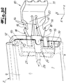
- the vertical rail has an approximately rectangular hollow box 6 and two thereof thereof in the transverse direction x extending leg 7, which surround the end portion a of the slats as a height direction y and the transverse direction x perpendicular thickness direction z.
- the passage formed between the two legs 7, in which the end portion a is received, opens into the interior of the hollow box 6.
- the two legs 7 and the hollow box 6 are formed as a bent metal profile. End is on the two legs.
- a plastic sealing strip 8 attached, which serves as a contact surface for the lamella 2 in the region of a lamellar body 9 likewise formed of a metallic sheet-metal profile.
- a securing hook 10 is inserted into an end-side recess of the lamella 2. With an angled portion 11 of the securing hook 10 engages behind the side guide 3, in which it engages in the interior of the hollow box 6. As a result, the lamella with the securing hooks 11 is secured against being pulled out in the lateral direction from the side guide 3. Expediently remains in the unloaded normal state between the angled portion 11 and the inside of the hollow box 6, a gap b, which is closed only by a tensile stress. Then the safety hook 10 is positively supported in the side guide 3, so that further extraction is no longer possible.
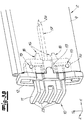
- the Fig. 3a shows a detail view of the end portion a of a partially broken blade 2 with a partially partially inserted safety hook 10.
- a plastic cap is attached, which completely borders the end opening of the blade 2 for insertion of the securing hook 10 ,
- the plastic cap 12 now engages with a centering nose 13 in an associated recess in the plate of the plate body 9.
- the plastic cap 12 is held approximately vertically in the vertical direction y on the lamellar body 9.
- the plastic cap 12 is located with a sleeve-shaped portion 14 on both sides of an inner side of the hollow profile and is supported on this.
- the securing hook 10 has in addition to the angled portion 11 two integrally adjoining fasteners in the form of latching hooks (16) and arranged therebetween also made of plastic integrally molded pin 17. Starting from the angled section 11 in the lateral direction x, the pin 17 has a greater length than the two latching hooks 16 so that it extends deeper into the interior of the lamella 2 in the installed state.
- the latching hooks 16 are each equipped with a front-side insertion bevel 18 in the insertion direction and a retaining surface 19 arranged on the rearward side facing away from the insertion direction.
- the thus formed hook-shaped portion is connected in each case by an elastically deformable support arm 20 with the remaining safety hook 10.
- the latching hooks 16 are compressed when hitting an obstacle in the direction of the pin 17. After overcoming the obstacle, you automatically spring back apart elastically.
- the holding surface 19 is according to Art a barb so inclined that the latching hooks are pulled apart in a subsequent tensile stress, so that the latching connection reinforced.
- an abutment 21 is provided within the sleeve-shaped portion 14, which on the one hand interact with the insertion bevel 18 during insertion of the latching hook 10 for compression of the latching hooks 16 and on the other hand a positive contact surface for the retaining surfaces 19 of the securing hook 10th form.
- securing hook 10 is provided with stabilizing ribs 23 both in the region of the angled section 11 and in the transition to the pin 17 and the latching hook 16. This is especially by a comparative consideration with the Fig. 4 , which represents the safety hook alone, clearly.
- the pin 17 further has a sharpened end 24, with which it is driven into a filling of the disk body 9. By the elongated shape of the pin 17, this is then supported in the insulation over its entire length dipping in this in the height direction y and the thickness direction z and can transmit forces in both directions.
- the pin 17 has a greater extension in the thickness direction z than in the vertical direction y in cross-section.
- the cross section is formed in the embodiment in approximately rectangular with beveled edges.
- a gap 25 which opens into limited by a circular arc segment bulges 26.
- the diameter of the bulges 26 is greater than the width of the gap 25th
Landscapes
- Engineering & Computer Science (AREA)
- Structural Engineering (AREA)
- Architecture (AREA)
- Civil Engineering (AREA)
- Operating, Guiding And Securing Of Roll- Type Closing Members (AREA)
Applications Claiming Priority (1)
| Application Number | Priority Date | Filing Date | Title |
|---|---|---|---|
| DE102016125677.3A DE102016125677A1 (de) | 2016-12-23 | 2016-12-23 | Lamellenrolltor |
Publications (1)
| Publication Number | Publication Date |
|---|---|
| EP3339560A1 true EP3339560A1 (fr) | 2018-06-27 |
Family
ID=59829274
Family Applications (1)
| Application Number | Title | Priority Date | Filing Date |
|---|---|---|---|
| EP17190083.0A Withdrawn EP3339560A1 (fr) | 2016-12-23 | 2017-09-08 | Porte roulante à lamelles et crochet de sécurité |
Country Status (2)
| Country | Link |
|---|---|
| EP (1) | EP3339560A1 (fr) |
| DE (1) | DE102016125677A1 (fr) |
Cited By (1)
| Publication number | Priority date | Publication date | Assignee | Title |
|---|---|---|---|---|
| DE102022117412A1 (de) | 2021-08-06 | 2023-02-09 | Hörmann Kg Dissen | Sturmanker-Endstück für Rolltorprofile sowie Verwendungen desselben |
Families Citing this family (1)
| Publication number | Priority date | Publication date | Assignee | Title |
|---|---|---|---|---|
| DE102020116649B3 (de) | 2020-06-24 | 2021-12-23 | Jäger - Engineering GmbH | Maschinentür und Maschine |
Citations (7)
| Publication number | Priority date | Publication date | Assignee | Title |
|---|---|---|---|---|
| BE636358A (fr) * | ||||
| DE4301070A1 (de) * | 1992-11-26 | 1994-06-01 | Gustav Stange | Verfahren und Vorrichtung zur Halterung von benachbarten Lamellen einer Rollade, Rolltores o. dgl. |
| EP0794313A1 (fr) * | 1996-03-07 | 1997-09-10 | Les Zelles | Système d'accrochage pour tablier de volets roulants |
| US6068040A (en) * | 1998-07-24 | 2000-05-30 | Alpine Overhead Doors, Inc. | Slat edge retainer for overhead rolling doors |
| DE20106088U1 (de) * | 2000-04-06 | 2001-06-07 | Rapid S.A., Puiseux-Pontoise | Rolladeneinrichtung mit aneinander angelenkten Lamellen und Führungsschienen für die Enden der Lamellen |
| DE20308668U1 (de) * | 2002-05-24 | 2003-08-28 | Hörmann KG Dissen, 49201 Dissen | Endstück für ein Glied eines mehrgliedrigen Gebäudeabschlussflügels sowie damit versehener Gebäudeabschluss |
| DE102009020079A1 (de) * | 2009-05-06 | 2010-11-11 | Hörmann KG Amshausen | Rolltorprofilstabausbildung mit Sturmanker sowie Sturmanker und Befestigungseinrichtung hierfür |
-
2016
- 2016-12-23 DE DE102016125677.3A patent/DE102016125677A1/de not_active Withdrawn
-
2017
- 2017-09-08 EP EP17190083.0A patent/EP3339560A1/fr not_active Withdrawn
Patent Citations (7)
| Publication number | Priority date | Publication date | Assignee | Title |
|---|---|---|---|---|
| BE636358A (fr) * | ||||
| DE4301070A1 (de) * | 1992-11-26 | 1994-06-01 | Gustav Stange | Verfahren und Vorrichtung zur Halterung von benachbarten Lamellen einer Rollade, Rolltores o. dgl. |
| EP0794313A1 (fr) * | 1996-03-07 | 1997-09-10 | Les Zelles | Système d'accrochage pour tablier de volets roulants |
| US6068040A (en) * | 1998-07-24 | 2000-05-30 | Alpine Overhead Doors, Inc. | Slat edge retainer for overhead rolling doors |
| DE20106088U1 (de) * | 2000-04-06 | 2001-06-07 | Rapid S.A., Puiseux-Pontoise | Rolladeneinrichtung mit aneinander angelenkten Lamellen und Führungsschienen für die Enden der Lamellen |
| DE20308668U1 (de) * | 2002-05-24 | 2003-08-28 | Hörmann KG Dissen, 49201 Dissen | Endstück für ein Glied eines mehrgliedrigen Gebäudeabschlussflügels sowie damit versehener Gebäudeabschluss |
| DE102009020079A1 (de) * | 2009-05-06 | 2010-11-11 | Hörmann KG Amshausen | Rolltorprofilstabausbildung mit Sturmanker sowie Sturmanker und Befestigungseinrichtung hierfür |
Cited By (1)
| Publication number | Priority date | Publication date | Assignee | Title |
|---|---|---|---|---|
| DE102022117412A1 (de) | 2021-08-06 | 2023-02-09 | Hörmann Kg Dissen | Sturmanker-Endstück für Rolltorprofile sowie Verwendungen desselben |
Also Published As
| Publication number | Publication date |
|---|---|
| DE102016125677A1 (de) | 2018-06-28 |
Similar Documents
| Publication | Publication Date | Title |
|---|---|---|
| EP0167137B1 (fr) | Lamelle de volet de dimensions réduites en aluminium profilé par des rouleaux | |
| EP1580393B1 (fr) | Porte | |
| EP3339560A1 (fr) | Porte roulante à lamelles et crochet de sécurité | |
| EP2354431B1 (fr) | Coffre de store avec rails de guidage | |
| DE102006005610B4 (de) | Insektenschutzrahmen | |
| EP3489450B1 (fr) | Porte | |
| EP2281995B1 (fr) | Volet Roulant | |
| AT517263B1 (de) | Schließvorrichtung für eine Schiebetür | |
| AT508177B1 (de) | Rollladen mit führungsschienen und anschlägen | |
| AT414008B (de) | Vorrichtung zum beschatten einer wandöffnung, insbesondere für ein fenster oder eine tür | |
| EP1947286B1 (fr) | Caisson de volet roulant | |
| DE19618912A1 (de) | Lamelle für ein Blatt eines vorzugsweise auf und ab bewegbaren Rollverschlusses für ein Tor, eine Tür, ein Fenster o. dgl. Öffnung | |
| DE19600951A1 (de) | Antriebsvorrichtung für einen Rolladen | |
| EP2623703B1 (fr) | Profilé de support | |
| DE19714112B4 (de) | Rolladen für eine asymmetrische Öffnung | |
| EP0185835B1 (fr) | Volet battant | |
| EP2233679B1 (fr) | Store à lamelles pour fenêtres triangulaires | |
| DE2501066A1 (de) | Rolladen | |
| EP3467243B1 (fr) | Porte, son procédé de fonctionnement et ensemble d'équipement complémentaire pour une porte | |
| DE1155897B (de) | Jalousietor | |
| WO2004029396A1 (fr) | Porte a coulissement rapide | |
| WO2016192913A1 (fr) | Dispositif d'occulation pour une vitre ou une région de toit vitré d'un habitacle de véhicule | |
| EP2089601B1 (fr) | Dispositif de fermeture | |
| DE102012019435A1 (de) | Rollladen und Panzeranbindungsmodul dafür | |
| EP3792439A1 (fr) | Fermeture coupe-feu |
Legal Events
| Date | Code | Title | Description |
|---|---|---|---|
| PUAI | Public reference made under article 153(3) epc to a published international application that has entered the european phase |
Free format text: ORIGINAL CODE: 0009012 |
|
| STAA | Information on the status of an ep patent application or granted ep patent |
Free format text: STATUS: THE APPLICATION HAS BEEN PUBLISHED |
|
| AK | Designated contracting states |
Kind code of ref document: A1 Designated state(s): AL AT BE BG CH CY CZ DE DK EE ES FI FR GB GR HR HU IE IS IT LI LT LU LV MC MK MT NL NO PL PT RO RS SE SI SK SM TR |
|
| AX | Request for extension of the european patent |
Extension state: BA ME |
|
| STAA | Information on the status of an ep patent application or granted ep patent |
Free format text: STATUS: REQUEST FOR EXAMINATION WAS MADE |
|
| 17P | Request for examination filed |
Effective date: 20181220 |
|
| RBV | Designated contracting states (corrected) |
Designated state(s): AL AT BE BG CH CY CZ DE DK EE ES FI FR GB GR HR HU IE IS IT LI LT LU LV MC MK MT NL NO PL PT RO RS SE SI SK SM TR |
|
| STAA | Information on the status of an ep patent application or granted ep patent |
Free format text: STATUS: EXAMINATION IS IN PROGRESS |
|
| 17Q | First examination report despatched |
Effective date: 20191030 |
|
| GRAP | Despatch of communication of intention to grant a patent |
Free format text: ORIGINAL CODE: EPIDOSNIGR1 |
|
| STAA | Information on the status of an ep patent application or granted ep patent |
Free format text: STATUS: GRANT OF PATENT IS INTENDED |
|
| INTG | Intention to grant announced |
Effective date: 20201110 |
|
| STAA | Information on the status of an ep patent application or granted ep patent |
Free format text: STATUS: THE APPLICATION IS DEEMED TO BE WITHDRAWN |
|
| 18D | Application deemed to be withdrawn |
Effective date: 20210323 |