EP3340067B1 - Mittelwertbestimmung - Google Patents
Mittelwertbestimmung Download PDFInfo
- Publication number
- EP3340067B1 EP3340067B1 EP17204566.8A EP17204566A EP3340067B1 EP 3340067 B1 EP3340067 B1 EP 3340067B1 EP 17204566 A EP17204566 A EP 17204566A EP 3340067 B1 EP3340067 B1 EP 3340067B1
- Authority
- EP
- European Patent Office
- Prior art keywords
- data
- subset
- data values
- values
- value
- Prior art date
- Legal status (The legal status is an assumption and is not a legal conclusion. Google has not performed a legal analysis and makes no representation as to the accuracy of the status listed.)
- Active
Links
Images



Classifications
-
- G—PHYSICS
- G06—COMPUTING OR CALCULATING; COUNTING
- G06T—IMAGE DATA PROCESSING OR GENERATION, IN GENERAL
- G06T5/00—Image enhancement or restoration
- G06T5/70—Denoising; Smoothing
-
- G—PHYSICS
- G06—COMPUTING OR CALCULATING; COUNTING
- G06F—ELECTRIC DIGITAL DATA PROCESSING
- G06F7/00—Methods or arrangements for processing data by operating upon the order or content of the data handled
- G06F7/02—Comparing digital values
- G06F7/026—Magnitude comparison, i.e. determining the relative order of operands based on their numerical value, e.g. window comparator
-
- G—PHYSICS
- G06—COMPUTING OR CALCULATING; COUNTING
- G06F—ELECTRIC DIGITAL DATA PROCESSING
- G06F17/00—Digital computing or data processing equipment or methods, specially adapted for specific functions
- G06F17/10—Complex mathematical operations
- G06F17/18—Complex mathematical operations for evaluating statistical data, e.g. average values, frequency distributions, probability functions, regression analysis
-
- G—PHYSICS
- G06—COMPUTING OR CALCULATING; COUNTING
- G06F—ELECTRIC DIGITAL DATA PROCESSING
- G06F7/00—Methods or arrangements for processing data by operating upon the order or content of the data handled
- G06F7/02—Comparing digital values
-
- G—PHYSICS
- G06—COMPUTING OR CALCULATING; COUNTING
- G06F—ELECTRIC DIGITAL DATA PROCESSING
- G06F7/00—Methods or arrangements for processing data by operating upon the order or content of the data handled
- G06F7/06—Arrangements for sorting, selecting, merging, or comparing data on individual record carriers
- G06F7/08—Sorting, i.e. grouping record carriers in numerical or other ordered sequence according to the classification of at least some of the information they carry
-
- G—PHYSICS
- G06—COMPUTING OR CALCULATING; COUNTING
- G06T—IMAGE DATA PROCESSING OR GENERATION, IN GENERAL
- G06T5/00—Image enhancement or restoration
- G06T5/20—Image enhancement or restoration using local operators
-
- G—PHYSICS
- G11—INFORMATION STORAGE
- G11B—INFORMATION STORAGE BASED ON RELATIVE MOVEMENT BETWEEN RECORD CARRIER AND TRANSDUCER
- G11B20/00—Signal processing not specific to the method of recording or reproducing; Circuits therefor
- G11B20/24—Signal processing not specific to the method of recording or reproducing; Circuits therefor for reducing noise
-
- G—PHYSICS
- G06—COMPUTING OR CALCULATING; COUNTING
- G06T—IMAGE DATA PROCESSING OR GENERATION, IN GENERAL
- G06T2207/00—Indexing scheme for image analysis or image enhancement
- G06T2207/20—Special algorithmic details
- G06T2207/20024—Filtering details
- G06T2207/20032—Median filtering
-
- G—PHYSICS
- G06—COMPUTING OR CALCULATING; COUNTING
- G06T—IMAGE DATA PROCESSING OR GENERATION, IN GENERAL
- G06T2207/00—Indexing scheme for image analysis or image enhancement
- G06T2207/20—Special algorithmic details
- G06T2207/20172—Image enhancement details
Definitions
- an image processing system may be used in a camera pipeline to process pixel values originating from image sensors in a camera to provide a set of processed pixel values representing a captured image.
- a median determination may be performed for many different purposes, e.g. to implement a median filter for attenuating impulsive noise (i.e. denoising), for defective pixel detection, or defective pixel correction to give just some examples.
- Algorithms for sorting a set of data values tend to use recursion, which is suitable for being implemented in software. As the number of data values in the set increases, the complexity involved in sorting the data values in software typically scales by a factor of (n log n). However, algorithms using recursion are not well suited for being implemented in hardware. Modules of some data processing systems are implemented in hardware (e.g. fixed function circuitry) rather than being implemented in software running on general purpose hardware, because hardware implementations can provide a more optimised system (e.g. in terms of processing latency, power consumption and the physical size of the processing system e.g. when implemented in silicon) for performing a specific function. Therefore, if a data processing system is intended to operate quickly (e.g.
- a device with limited battery life e.g. a mobile device such as a smartphone, tablet, camera, laptop, etc.
- SOC System On Chip
- a hardware implementation of the data processing system is often implemented.
- a data processing system which tends to be implemented in hardware is an image processing system used in a camera pipeline for processing pixel values received from an image sensor for providing processed pixel values to be captured and/or displayed to a user in real-time, e.g. on the screen of a tablet, smartphone or handheld camera etc.
- One method for implementing a median determining unit in hardware is to use a Bubble sort algorithm.
- the Bubble sort algorithm (which may be referred to as a "sinking sort") comparisons between two of the data values are repeatedly performed to compare each pair of adjacent data values in turn and swap them if they are in the wrong order. The pass through the data values is repeated until no swaps are needed, which indicates that the data values are sorted into the correct order.
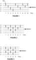
- Figure 1 shows an example in which five data values are sorted using the Bubble sort algorithm.
- the horizontal axis in Figure 1 represents units of time, e.g. clock cycles or processing cycles.
- a unit of time may be the time taken to perform a compare and swap operation.
- the time to do a compare increases with the number of bits in the operands being compared, e.g. it takes longer to compare two 12-bit values than to compare two 5-bit values.
- the horizontal lines A to E represent positions between which data values may move as the sort process progresses. The way in which data values are represented at particular positions and times depends on how the sorter is implemented. For example, data values may be stored in registers, or may exist as signals in logic units.
- the data values in positions B and C are compared and if the data value in position C is greater than the data value in position B then the data values are swapped in positions B and C, otherwise the data values in positions B and C are not swapped in time instance 2.
- the data values in positions C and D are compared and if the data value in position D is greater than the data value in position C then the data values are swapped in positions C and D, otherwise the data values in positions C and D are not swapped in time instance 3.
- the data values in positions D and E are compared and if the data value in position E is greater than the data value in position D then the data values are swapped in positions D and E, otherwise the data values in positions D and E are not swapped in time instance 4.
- the smallest data value will be in position E.
- Figure 1 is conceptually simple to understand, but the efficiency of the sorting algorithm can be improved, in terms of the time taken to perform the search.
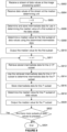
- Figure 2 shows an example in which multiple comparisons can be performed at the same time instance on different pairings of positions. For example, at time instance 3, the data values in positions A and B are compared and optionally swapped, at the same time that the data values in positions C and D are compared and optionally swapped. In the example shown in Figure 1 , the data values in positions A and B do not change at time instances 3 and 4, so the comparison that is performed at time instance 5 in Figure 1 , can be implemented at time instance 3 in the example shown in Figure 2 , without effecting the outcome of the sorting process.
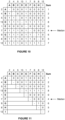
- Figure 4 shows how the same approach as that shown in Figure 3 can be applied to the case of 7 inputs.
- 21 comparisons are performed and the sort takes 7 units of time to complete.
- the example shown in Figure 4 is a simplification, and in a real system one or more retiming stages may be required between some of the time instances at which comparisons are performed, so that the signals can be safely swapped between positions before the values in those positions are subsequently used in further comparisons.
- there may be propagation delays when data values are swapped between positions so latency may be added to the sort process to account for the propagation delays. For example, the number of sequential transistors on the worst case path through the logic (i.e.
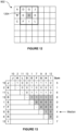
- Figure 5 shows how the same approach as that shown in Figure 3 can be applied to the case of 9 inputs.
- 36 comparisons are performed and the sort takes 9 units of time to complete, plus some time to allow for the propagation delays, as described above.
- the processing module 610 consists entirely of the median determining unit 612, but in some other examples, the processing module 610 may include other functionality which makes use of median values determined by the median determining unit 612.
- step S814 involves performing 21 comparisons of pairs of data values of the current subset in order to determine the unhashed indications shown in Figure 13 . Therefore, in this example, the processing logic 702 comprises 21 comparison modules 706 configured to determine the 21 indications for pairings involving one or more data values of the current subset which do not overlap with the previous subset.
- the updating of the table shown in Figure 11 to arrive at the table shown in Figure 13 could be implemented in multiple (e.g. three) phases, e.g. by substituting one data value at a time.
- the indications (e.g. as shown in Figure 13 ) for the pairings involving one or more data values of the current subset which do not overlap with the previous subset may be determined in multiple phases.
- data value L may substitute data value C to produce a table of intermediate data values with respective rows for data values J, K, L, D, E, F, G, H and I, as shown in Figure 13 .
- Dividing the processing into multiple (e.g. three) phases reduces the number of comparisons that are performed in a single phase.
- the number of comparison units included in the system may be the same as the number of comparisons that are performed in a single phase.
- the number of phases may be equal to the number of data values of the current subset which do not overlap with the previous subset. Therefore, when processing in a raster scan order, the number of phases may be equal to the number of rows of data values in a subset.
- step S816 the intermediate data (e.g. the table shown in Figure 13 ) for the current subset (i.e. the i th subset) is stored in the data storage logic 704.
- step S818 the processing logic 702 determines a median value of the data values within the current subset (i.e. the i th subset) using the intermediate data determined in step S814 for the current subset (i.e. the i th subset).
- Step S818 is similar to step S808 in that it involves determining the results of the sums for each of the data values in the current subset and then determining the median value by selecting one of the data values in the subset based on the determined results of the sums.
- the data value G which has a value of nine, has a sum of four, so the median value for the current subset is determined to be nine. Therefore, the median value determined for the pixel value H is 9 (i.e. the median value is given by the pixel value G).
- step S820 the median value (e.g. a value of 9) determined for the i th subset is outputted from the median determining unit 612 (e.g. to represent the median value determined for the data value H), for use in the image processing system 604.
- the median value may be used by the processing module 610, used by other processing modules within the image processing system 604, and/or outputted from the image processing system 604.
- step S822 the processing logic 702 determines whether there are any more subsets of data values to process, and if there are, then the method passes back to step S811 in which the subset index i is incremented and the method repeats by performing steps S812 to S820 for the next subset. If it is determined in step S822 that there are no more subsets of data values to process then the method ends in step S824.
- the kernel which is used may be adapted.
- the treatment of edge pixels can vary in different implementations.
- each median value is outputted as it has been determined (e.g. in steps S810 and S820). It would be possible to output groups of median values in batches when a whole batch of median values has been determined. For example, when median values for a row of pixel values have been determined then all of the median values for that row could be outputted together. Furthermore, the method could wait until all of the median values have been determined for all of the pixels within an image before any of them are outputted.
- step S814 the processing logic 702 replaces the indications for the pairings involving one or more data values of the ( i - 1) th subset which do not overlap with the i th subset (i.e. involving data values A, B and/or C in the example shown in Figures 11 and 13 ) with the indications determined by the comparison modules 706 for the pairings involving one or more data values of the i th subset which do not overlap with the ( i - 1) th subset (i.e. involving data values J, K and/or L in the example shown in Figures 11 and 13 ).
- This allows the previous indications i.e.
- the hashed indications in Figure 13 which do not change to stay where they are in the table.
- the indications for the comparisons involving only data values which overlap with both subsets i and ( i - 1) i.e. indications for comparisons involving two of data values D, E, F, G, H and I in the example shown in Figures 11 and 13
- the new indications for comparisons involving the new data values J, K and/or L could be placed at the bottom of the table.
- the replacement of the indications may be performed in multiple phases, such that single data value replacements are implemented in each of the phases, so the number of comparisons that are performed in each phase is reduced. This simplifies the routing problem and reduces the number of comparison units that are implemented, thereby reducing the size and complexity of the hardware.
- the first median calculation (in steps S806 and S808) is performed for data value E, but this is just to simplify the description of the method, because the data value E is the first data value in the stream on which a 3x3 kernel can be centred without extending the image, e.g. by reflection across the image edge.
- median values will most likely be determined for each data value in the stream in turn, i.e. when the data values are received in raster scan order, then the top row of data values is processed first, from left to right, and then the next row of data values is processed, and so on. Therefore, the first data value for which a median value is determined is likely to be data value A, then D, then G, then J, etc.
- steps S806 and S808 are performed to determine the indications in the table without reusing previously determined indications, and then for subsequent data values in a row the steps S812 to S818 are performed to determine the indications in the table based on previously determined indications.
- the subsets of data values represent 3x3 blocks of data values with the 2D array 902.
- the subsets of data values may be other shapes or sizes, e.g. the subsets of data values may represent one of: 5x5 blocks of data values, 7x7 blocks of data values, 3x5 blocks of data values, 5x7 blocks of data values, 7x9 blocks of data values or 9x9 blocks of data values to give just some examples.
- an odd number of data values are included in each of the subsets, but it would be possible for a subset of data value to include an even number of data values.
- the median value can be determined from these two middle data values, (e.g. as the lower of the two, the higher of the two or the mean of the two middle data values).
- the data value for which a subset of data values is passed to the median determining unit 612 may be in the centre of the subset of data values (e.g. the data value E is in the centre of the kernel 904, and the data value H is in the centre of the kernel 1204). However, this is not always the case. For example, near to the edges of the array, the data value for which a subset of data values is passed to the median determining unit 612 might not be in the centre of the subset of data values.
- all of the subsets might be the same size and shape, but in other examples some of the subsets may differ in size and/or shape.
- subsets for determining the median value for data values on or near an edge of the 2D array may be smaller than subsets for determining the median value for data values which are far from the edges of the 2D array.
- the rolling window approach to determining median values for a stream of data values improves the efficiency of the median determining unit 612 by reducing the number of comparisons that are performed (compared to determining each median value separately).
- the subsets of data values increase in size the amount of overlap between consecutive subsets which are processed increases, such that the efficiency gains achieved with the approach described herein increase.
- comparisons are performed for determining 21 of the 36 (i.e. 58%) indications shown in Figure 13 for each of a plurality of subsets following a first subset.
- comparisons are performed for determining 315 of 1176 (i.e. 27%) indications for each subset following a first subset. If the updating of the table is done in multiple phases (e.g. seven phases), each phase would include 48 comparisons. Reducing the number of comparisons that are performed reduces the processing power and time of determining a median value and also reduces the amount of hardware (i.e. the number of comparison modules) that is implemented in the processing logic of the median determining unit.
- subsets which represent blocks of pixel values which are wider than they are tall may be beneficial to use. Since the line store module 608 stores rows of data values, (e.g. as they arrive in raster scan order), a reduction in the number of rows means that the line store module 608 can have a reduced size, and a delay incurred in waiting for the line store module 608 to receive enough pixel values for the median determining unit 612 to process pixel values can be reduced. Whilst it may be advantageous to reduce the number of rows in the subsets for the reasons given above, the same is not true for reducing the number of columns in the subsets (when the data values are received in rows, e.g.
- subsets which have more columns than rows (i.e. they are wider than they are tall). This allows the subsets to retain a large overall size, whilst reducing the number of rows in the subsets.
- the size and shape of the subsets may depend on the use for which the median values are being determined (i.e. the function of the processing module 610).
- the median determining unit 612 can operate on a stream of pixel values, irrespective of where the pixel values originated.
- pixel values of an image could be generated by a graphics processing unit (rather than being captured by an image sensor), and the median determining unit 612 could be used to determine median values as part of the processing of the pixel values within the graphics processing unit.
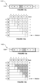
- Figure 14a illustrates an example in which the stream of data values 1402 represents a one-dimensional array (i.e. a sequence) of data values.
- each of the subsets of data values within the stream represents a contiguous block of data values within the one-dimensional array.
- the kernel 1404 represents a subset of data values (including data values A, B, C, D, E, F and G) which can be used for determining a median value for the data value D.
- the subset 1404 includes seven data values.
- FIG. 8 The method shown in Figure 8 can be used to determine median values for the data values within the 1D array 1402.
- Figure 14b shows a table of indications determined for the subset 1404 in step S806.
- the median determining unit 612 determines a median value for the next data value (data value E) in the stream by finding the median of the data values within the kernel 1504, as shown in Figure 15a .
- the kernel 1504 represents a subset of the data values including the data values B, C, D, E, F, G and H.
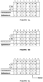
- step S812 the processing logic 702 retrieves, from the data storage logic 704, the intermediate data (i.e. the table shown in Figure 14b ) stored in step S806.
- the indications in the bottom six rows of the table will not need to be updated compared to the table shown in Figure 14b .
- the top row of the table is updated to include indications for the new data value (data value H) in place of the indications for the old data value (data value A).
- the data value H has a value of 8.
- the results of the sums can then be determined in step S818, and the median can be selected by finding the data value which has a sum equal to 3. Therefore in step S818 the value G (i.e. a value of 4) is determined to be the median value for the subset 1504.
- the process repeats for each of a plurality of data values in the stream.
- a 1D stream of data values could be used if the data processing system is an audio processing system and the data values are audio samples of an audio signal.
- the audio signal could be received and sampled at a microphone and the audio samples can be passed to the audio processing system.
- the audio processing system may perform some processing functions (some of which may implement a median determining unit as described herein) on the audio samples before outputting the processing audio signal, e.g. via a speaker.
- a 1D stream of data values could be used if the data processing system is a signal processing system and the data values are signal samples of a transmitted signal.
- the signal could be received over a wired or wireless channel, at a device in which the signal processing system is implemented. The device can sample the received signal and then the signal processing system may perform some processing functions (some of which may implement a median determining unit as described herein) on the received signal samples in order to extract the data from the received signal.
- the intermediate data which is stored in the data storage logic 704 takes the form of the indications in the tables shown in Figures 11 and 13 .
- the intermediate data could take other forms.
- the intermediate data for a subset of data values may comprise, for each of the data values in the subset, an index value indicating a sorted position of the data value within the subset.
- the results of the sums shown in Figures 11 and 13 could be stored as indices for the data values. So, taking Figure 11 as an example, rather than storing all of the indications in the table, just the results of the sums are stored. The results of the sums can be determined in the same way as described above.
- an index of 1 is stored for data value A
- an index of 2 is stored for data value B
- an index of 3 is stored for data value C
- an index of 8 is stored for data value D
- an index of 0 is stored for data value E
- an index of 4 is stored for data value F
- an index of 6 is stored for data value G
- an index of 5 is stored for data value H
- an index of 7 is stored for data value I.
- the processing logic can determine a median value of the data values within a subset by selecting one of the data values in the subset based on the index values.
- this example reduces the amount of intermediate data that is stored in the data storage logic 704 between iterations, in the example described below some indications (i.e. comparisons) need to be re-computed in a current iteration that have been computed in the previous iteration; whereas in the examples described above with reference to Figures 10 to 15b these indications would not need to be recomputed because they are stored in the intermediate data. So, there is a trade-off between reducing the amount of intermediate data that is stored between iterations and increasing the number of comparisons that are performed in each iteration.
- the index values of a previous subset can be used to determine index values for a current subset.
- the processing logic can retrieve the intermediate data (i.e. the index values) stored for the previous subset and use the retrieved index values to determine index values for a current subset, e.g. as described below.
- Index values of one or more data values of the previous subset which overlap with the current subset are identified. For each of one or more data values of the current subset which do overlap with the previous subset, a determination is made as to whether or not to increment or decrement the index value for the data value based on: (i) a comparison of the data value with the one or more data values of the previous subset which do not overlap with the current subset, and (ii) a comparison of the data value with the one or more data values of the current subset which do not overlap with the previous subset.
- One or more index values are identified to be assigned to the one or more data values of the current subset which do not overlap with the previous subset by finding gaps in the sequence of index values of the data values in the current subset, such that the index values in the current subset form a contiguous sequence.
- the processing logic determines a median value for the data value H shown in Figure 12 , it is finding a median value of the data values in the subset 1204, which includes data values D, E, F, G, H, I, J, K and L.
- the processing logic can identify the index values of the data values of the previous subset 904, i.e. data values A, B, C, D, E, F, G, H and I.
- There are three new data values (J, K and L) in the current subset which replace three old data values (A, B and C) in the previous subset, and this can be done in three phases.
- Figure 16a illustrates a first phase, in which the data value J replaces the data value A.
- Figure 16a shows the rows of indications for data values A and J.
- index values i.e. the previous sums
- Figure 16a The identified index values (i.e. the previous sums) are shown in Figure 16a as 2, 3, 8, 0, 4, 6, 5 and 7 for data values B, C, D, E, F, G, H and I respectively. It can be seen that these sums match those shown in Figure 11 .
- the processing logic determines an index value for the data value by comparing the data value to the other data values in the current subset 1204.
- R denotes a data value being retired (e.g. data value A in the first phase shown in Figure 16a )
- N denotes a new data value of the current subset (e.g. data value J in the first phase shown in Figure 16a )
- X denotes each respective existing data value that is being kept (e.g. data values B, C, D, E, F, G, H and I in the first phase shown in Figure 16a )
- the sum values of the existing data values (X) can be updated as follows:
- Figure 16b illustrates a second phase, in which the data value K replaces the data value B.
- Figure 16b shows the rows of indications for data values B and K.
- the identified index values i.e. the previous sums
- the identified index values are shown in Figure 16b as 6, 2, 8, 0, 3, 5, 4 and 7 for data values J, C, D, E, F, G, H and I respectively. It can be seen that these sums match those shown as updated sums in Figure 16a .
- the data value K has a value of 2, and when it is compared with the values of data values J, C, D, E, F, G, H and I, the indications of the comparisons between each of the existing data values (J and C to I) with data value B and with data value K are shown in the first two rows of the table in Figure 16b .
- the sums for all of the existing data values J, C, D, E, F, G, H and I are not changed. Therefore the updated sums (i.e. the updated index values) for data values J, C, D, E, F, G, H and I are 6, 2, 8, 0, 3, 5, 4 and 7 respectively.
- Figure 16c illustrates a third phase, in which the data value L replaces the data value C.
- Figure 16c shows the rows of indications for data values C and L.
- the identified index values i.e. the previous sums
- the identified index values are shown in Figure 16c as 6, 1, 8, 0, 3, 5, 4 and 7 for data values J, K, D, E, F, G, H and I respectively. It can be seen that these sums match those shown as updated sums in Figure 16b .
- the data value L has a value of 11, and when it is compared with the values of data values J, K, D, E, F, G, H and I, the indications of the comparisons between each of the existing data values (J, K and D to I) with data value C and with data value L are shown in the first two rows of the table in Figure 16c .
- the sums for data values J, F, G and H are decremented, whilst the sums for data values K, D, E and I do not change. Therefore the updated sums (i.e. the updated index values) for data values J, K, D, E, F, G, H and I are 5, 1, 8, 0, 2, 4, 3 and 7 respectively.
- the examples described herein involve determining median values in a rolling manner for different data values from a stream of data values, such that the intermediate data used for determining the median value of a first subset of the received data values is stored and can be used for determining the median value of a second subset of the received data values which partially overlaps with the first subset.
- the median determining units described herein are shown in Figures 6 and 7 as comprising a number of functional blocks. This is schematic only and is not intended to define a strict division between different logic elements of such entities. Each functional block may be provided in any suitable manner. It is to be understood that intermediate values described herein as being formed by a median determining unit need not be physically generated by the median determining unit at any point and may merely represent logical values which conveniently describe the processing performed by the median determining unit between its input and output.
- the median determining units described herein may be embodied in hardware on an integrated circuit.
- the median determining units described herein may be configured to perform any of the methods described herein.
- any of the functions, methods, techniques or components described above can be implemented in software, firmware, hardware (e.g., fixed logic circuitry), or any combination thereof.
- the terms “module,” “functionality,” “component”, “element”, “unit”, “block” and “logic” may be used herein to generally represent software, firmware, hardware, or any combination thereof.
- the module, functionality, component, element, unit, block or logic represents program code that performs the specified tasks when executed on a processor.
- a computer-readable storage medium examples include a random-access memory (RAM), read-only memory (ROM), an optical disc, flash memory, hard disk memory, and other memory devices that may use magnetic, optical, and other techniques to store instructions or other data and that can be accessed by a machine.
- RAM random-access memory
- ROM read-only memory
- optical disc optical disc
- flash memory hard disk memory
- hard disk memory and other memory devices that may use magnetic, optical, and other techniques to store instructions or other data and that can be accessed by a machine.
- a processor, computer, or computer system may be any kind of device, machine or dedicated circuit, or collection or portion thereof, with processing capability such that it can execute instructions.
- a processor may be any kind of general purpose or dedicated processor, such as a CPU, GPU, System-on-chip, state machine, media processor, an application-specific integrated circuit (ASIC), a programmable logic array, a field-programmable gate array (FPGA), or the like.
- a computer or computer system may comprise one or more processors.
- HDL hardware description language
- An integrated circuit definition dataset may be, for example, an integrated circuit description.
- a method of manufacturing at an integrated circuit manufacturing system, a median determining unit or data processing system as described herein. Furthermore, there may be provided an integrated circuit definition dataset that, when processed in an integrated circuit manufacturing system, causes the method of manufacturing a median determining unit or data processing system to be performed.
- An integrated circuit definition dataset may be in the form of computer code, for example as a netlist, code for configuring a programmable chip, as a hardware description language defining an integrated circuit at any level, including as register transfer level (RTL) code, as high-level circuit representations such as Verilog or VHDL, and as low-level circuit representations such as OASIS (RTM) and GDSII.
- RTL register transfer level
- RTM OASIS
- GDSII GDSI
- one or more intermediate user steps may be required in order for a computer system configured for generating a manufacturing definition of an integrated circuit to execute code defining an integrated circuit so as to generate the manufacturing definition of that integrated circuit.
- Figure 17 shows an example of an integrated circuit (IC) manufacturing system 1702 which is configured to manufacture a median determining unit as described in any of the examples herein.
- the IC manufacturing system 1702 comprises a layout processing system 1704 and an integrated circuit generation system 1706.
- the IC manufacturing system 1702 is configured to receive an IC definition dataset (e.g. defining a median determining unit as described in any of the examples herein), process the IC definition dataset, and generate an IC according to the IC definition dataset (e.g. which embodies a median determining unit as described in any of the examples herein).
- the processing of the IC definition dataset configures the IC manufacturing system 1702 to manufacture an integrated circuit embodying a median determining unit as described in any of the examples herein.
- the layout processing system 1704 is configured to receive and process the IC definition dataset to determine a circuit layout.
- Methods of determining a circuit layout from an IC definition dataset are known in the art, and for example may involve synthesising RTL code to determine a gate level representation of a circuit to be generated, e.g. in terms of logical components (e.g. NAND, NOR, AND, OR, MUX and FLIP-FLOP components).
- a circuit layout can be determined from the gate level representation of the circuit by determining positional information for the logical components. This may be done automatically or with user involvement in order to optimise the circuit layout.
- the layout processing system 1704 may output a circuit layout definition to the IC generation system 1706.
- a circuit layout definition may be, for example, a circuit layout description.
- the IC generation system 1706 generates an IC according to the circuit layout definition, as is known in the art.
- the IC generation system 1706 may implement a semiconductor device fabrication process to generate the IC, which may involve a multiple-step sequence of photo lithographic and chemical processing steps during which electronic circuits are gradually created on a wafer made of semiconducting material.
- the circuit layout definition may be in the form of a mask which can be used in a lithographic process for generating an IC according to the circuit definition.
- the circuit layout definition provided to the IC generation system 1706 may be in the form of computer-readable code which the IC generation system 1706 can use to form a suitable mask for use in generating an IC.
- the different processes performed by the IC manufacturing system 1702 may be implemented all in one location, e.g. by one party.
- the IC manufacturing system 1702 may be a distributed system such that some of the processes may be performed at different locations, and may be performed by different parties.
- some of the stages of: (i) synthesising RTL code representing the IC definition dataset to form a gate level representation of a circuit to be generated, (ii) generating a circuit layout based on the gate level representation, (iii) forming a mask in accordance with the circuit layout, and (iv) fabricating an integrated circuit using the mask may be performed in different locations and/or by different parties.
- processing of the integrated circuit definition dataset at an integrated circuit manufacturing system may configure the system to manufacture a median determining unit without the IC definition dataset being processed so as to determine a circuit layout.
- an integrated circuit definition dataset may define the configuration of a reconfigurable processor, such as an FPGA, and the processing of that dataset may configure an IC manufacturing system to generate a reconfigurable processor having that defined configuration (e.g. by loading configuration data to the FPGA).
- an integrated circuit manufacturing definition dataset when processed in an integrated circuit manufacturing system, may cause an integrated circuit manufacturing system to generate a device as described herein.
- the configuration of an integrated circuit manufacturing system in the manner described above with respect to Figure 17 by an integrated circuit manufacturing definition dataset may cause a device as described herein to be manufactured.
- an integrated circuit definition dataset could include software which runs on hardware defined at the dataset or in combination with hardware defined at the dataset.
- the IC generation system may further be configured by an integrated circuit definition dataset to, on manufacturing an integrated circuit, load firmware onto that integrated circuit in accordance with program code defined at the integrated circuit definition dataset or otherwise provide program code with the integrated circuit for use with the integrated circuit.
- performance improvements may include one or more of increased computational performance, reduced latency, increased throughput, and/or reduced power consumption.
- performance improvements can be traded-off against the physical implementation, thereby improving the method of manufacture. For example, a performance improvement may be traded against layout area, thereby matching the performance of a known implementation but using less silicon. This may be done, for example, by reusing functional blocks in a serialised fashion or sharing functional blocks between elements of the devices, apparatus, modules and/or systems.
Landscapes
- Engineering & Computer Science (AREA)
- Physics & Mathematics (AREA)
- General Physics & Mathematics (AREA)
- Theoretical Computer Science (AREA)
- Data Mining & Analysis (AREA)
- Computational Mathematics (AREA)
- Mathematical Analysis (AREA)
- Mathematical Optimization (AREA)
- Pure & Applied Mathematics (AREA)
- Mathematical Physics (AREA)
- General Engineering & Computer Science (AREA)
- Algebra (AREA)
- Software Systems (AREA)
- Databases & Information Systems (AREA)
- Probability & Statistics with Applications (AREA)
- Operations Research (AREA)
- Life Sciences & Earth Sciences (AREA)
- Evolutionary Biology (AREA)
- Bioinformatics & Computational Biology (AREA)
- Bioinformatics & Cheminformatics (AREA)
- Signal Processing (AREA)
- Image Processing (AREA)
- Computer Hardware Design (AREA)
- Facsimile Image Signal Circuits (AREA)
Claims (15)
- Datenverarbeitungssystem (604), das so konfiguriert ist, dass es einen Strom von Datenwerten verarbeitet, wobei das Datenverarbeitungssystem (604) eine Medianermittlungseinheit (612) umfasst, die in Hardware implementiert ist, die so konfiguriert ist, dass sie Datenwerte des Stroms empfängt und Medianwerte zur Verwendung im Datenverarbeitungssystem (604) ermittelt, wobei die Medianermittlungseinheit (612) Folgendes umfasst:Datenspeicherlogik (704), die so konfiguriert ist, dass sie Zwischendaten zur Verwendung bei der Ermittlung von Medianwerten speichert; undVerarbeitungslogik (702), die in einer Schaltung mit fester Funktion implementiert und so konfiguriert ist, dass sie:Zwischendaten zur Verwendung bei der Ermittlung eines Medianwerts einer ersten Teilmenge der empfangenen Datenwerte des Stroms ermittelt und veranlasst, dass die ermittelten Zwischendaten in der Datenspeicherlogik (704) gespeichert werden;einen Medianwert der empfangenen Datenwerte in der ersten Teilmenge unter Verwendung der ermittelten Zwischendaten ermittelt; undfür jede der zumindest einen weiteren Teilmenge der empfangenen Datenwerte des Stroms:• die Zwischendaten aus der Datenspeicherlogik (704) abruft, die für eine vorherige Teilmenge von Datenwerten ermittelt wurden;• die abgerufenen Zwischendaten für die vorherige Teilmenge von Datenwerten verwendet, um Zwischendaten zur Verwendung bei der Ermittlung eines Medianwerts der aktuellen Teilmenge von empfangenen Datenwerten des Stroms zu ermitteln, wobei die aktuelle Teilmenge von Datenwerten zumindest teilweise mit der vorherigen Teilmenge von Datenwerten überlappt;• veranlasst, dass die ermittelten Zwischendaten für die aktuelle Teilmenge von Datenwerten in der Datenspeicherlogik (704) gespeichert werden; und• einen Medianwert der empfangenen Datenwerte in der aktuellen Teilmenge unter Verwendung der ermittelten Zwischendaten für die aktuelle Teilmenge ermittelt;wobei die Medianermittlungseinheit (612) ferner so konfiguriert ist, dass sie die ermittelten Medianwerte zur Verwendung im Datenverarbeitungssystem (604) ausgibt;dadurch gekennzeichnet, dass:die Zwischendaten für eine Teilmenge von Datenwerten für jede Paarung von Datenwerten in der Teilmenge eine Angabe darüber umfassen, welcher der Datenwerte der Paarung größer ist; unddie Verarbeitungslogik (702), die in einer Schaltung mit fester Funktion implementiert ist, so konfiguriert ist, dass sie einen Medianwert der Datenwerte in einer Teilmenge von Datenwerten durch Folgendes ermittelt:für jeden jeweiligen Datenwert in der Teilmenge, basierend auf den Angaben für die Paarungen, die den jeweiligen Datenwert umfassen, Ermitteln des Ergebnisses einer Summe, die die Anzahl anderer Datenwerte in der Teilmenge angibt, um die der jeweilige Datenwert größer als ist; undAuswählen, basierend auf den ermittelten Ergebnissen der Summen, eines der Datenwerte in der Teilmenge, wodurch der Medianwert der Datenwerte in der Teilmenge ermittelt wird.
- Datenverarbeitungssystem (604) nach Anspruch 1, wobei die Verarbeitungslogik (702) eine Vielzahl von Vergleichsmodulen (706) umfasst, die so konfiguriert sind, dass sie eine jeweilige Vielzahl von Angaben für Paarungen ermittelt, die einen oder mehrere Datenwerte der aktuellen Teilmenge umfassen, die nicht mit der vorherigen Teilmenge überlappen.
- Datenverarbeitungssystem (604) nach Anspruch 2, wobei die Verarbeitungslogik (702) so konfiguriert ist, dass sie die Angaben für Paarungen, die einen oder mehrere Datenwerte der vorhergehenden Teilmenge umfassen, die nicht mit der aktuellen Teilmenge von Datenwerten überlappen, durch die Vielzahl von Angaben ersetzt, die durch die Vielzahl von Vergleichsmodulen (706) für die Paarungen ermittelt werden, die einen oder mehrere Datenwerte der aktuellen Teilmenge umfassen, die nicht mit der vorherigen Teilmenge überlappen.
- Datenverarbeitungssystem (604) nach Anspruch 2 oder 3, wobei die Verarbeitungslogik (702) so konfiguriert ist, dass sie, wenn mehr als ein Datenwert der aktuellen Teilmenge nicht mit der vorherigen Teilmenge überlappt, die Vielzahl von Anzeigen in mehreren Phasen ermittelt, wobei in jeder der Phasen ein einzelner der Datenwerte der aktuellen Teilmenge, der nicht mit der vorherigen Teilmenge überlappt, einen der Datenwerte der vorherigen Teilmenge ersetzt, der nicht mit der aktuellen Teilmenge überlappt.
- Datenverarbeitungssystem (604) nach einem der vorhergehenden Ansprüche, wobei die Verarbeitungslogik (702) so konfiguriert ist, dass sie jedem Datenwert in der Teilmenge eine unterschiedliche Unterreferenz hinzufügt.
- Datenverarbeitungssystem (604) nach einem der vorhergehenden Ansprüche, wobei der Strom von Datenwerten eine zweidimensionale Anordnung (902) von Datenwerten darstellt, wobei jede der Teilmengen von Datenwerten im Strom von Datenwerten einen zusammenhängenden Block von Datenwerten in der zweidimensionalen Anordnung (902) darstellt.
- Datenverarbeitungssystem (604) nach Anspruch 6, wobei das Datenverarbeitungssystem (604) ein Bildverarbeitungssystem (604) ist, und wobei die Datenwerte Pixelwerte sind.
- Datenverarbeitungssystem (604) nach einem der Ansprüche 1 bis 5, wobei der Strom von Datenwerten eine eindimensionale Anordnung (1402) von Datenwerten darstellt, wobei jede der Teilmengen von Datenwerten im Strom von Datenwerten einen zusammenhängenden Block von Datenwerten in der eindimensionalen Anordnung (1402) darstellt.
- Datenverarbeitungssystem nach Anspruch 8, wobei das Datenverarbeitungssystem:ein Audioverarbeitungssystem ist, und wobei die Datenwerte Audio-Abtastwerte eines Audiosignals sind; oderein Signalverarbeitungssystem ist, und wobei die Datenwerte Signal-Abtastwerte eines übertragenen Signals sind.
- Verfahren zum Ermitteln von Medianwerten, das von einem Datenverarbeitungssystem (604) ausgeführt wird, das einen Strom von Datenwerten verarbeitet, wobei das Verfahren Folgendes umfasst:Empfangen von Datenwerten des Stroms an einer hardwareimplementierten Medianermittlungseinheit (612) des Datenverarbeitungssystems (604); undAusführen der folgenden Funktionen mit einer Schaltung mit fester Funktion der Medianermittlungseinheit (604):Ermitteln und Speichern von Zwischendaten zur Verwendung bei der Ermittlung eines Medianwerts einer ersten Teilmenge der empfangenen Datenwerte des Stroms;Ermitteln eines Medianwerts der empfangenen Datenwerte in der ersten Teilmenge unter Verwendung der ermittelten Zwischendaten; undfür jede der zumindest einen weiteren Teilmenge der empfangenen Datenwerte des Stroms:• Verwenden der gespeicherten Zwischendaten, die für eine vorherige Teilmenge von Datenwerten ermittelt wurden, um Zwischendaten zur Verwendung bei der Ermittlung eines Medianwerts der aktuellen Teilmenge von empfangenen Datenwerten des Stroms zu ermitteln, wobei die aktuelle Teilmenge von Datenwerten zumindest teilweise mit der vorherigen Teilmenge von Datenwerten überlappt;• Speichern der ermittelten Zwischendaten für die aktuelle Teilmenge von Datenwerten; und• Ermitteln eines Medianwerts der empfangenen Datenwerte in der aktuellen Teilmenge unter Verwendung der ermittelten Zwischendaten für die aktuelle Teilmenge;wobei das Verfahren ferner das Ausgeben der ermittelten Medianwerte zur Verwendung im Datenverarbeitungssystem (604) umfasst;dadurch gekennzeichnet, dass:die Zwischendaten für eine Teilmenge von Datenwerten für jede Paarung von Datenwerten in der Teilmenge eine Angabe darüber umfassen, welcher der Datenwerte der Paarung größer ist; unddie Schaltung mit fester Funktion der Medianermittlungseinheit (612) einen Medianwert der Datenwerte in einer Teilmenge von Datenwerten durch Folgendes ermittelt:für jeden jeweiligen Datenwert in der Teilmenge, basierend auf den Angaben für die Paarungen, die den jeweiligen Datenwert umfassen, Ermitteln des Ergebnisses einer Summe, die die Anzahl anderer Datenwerte in der Teilmenge angibt, um die der jeweilige Datenwert größer als ist; undAuswählen, basierend auf den ermittelten Ergebnissen der Summen, eines der Datenwerte in der Teilmenge, wodurch der Medianwert der Datenwerte in der Teilmenge ermittelt wird.
- Verfahren nach Anspruch 10, wobei das Verwenden der gespeicherten Zwischendaten, die für eine vorherige Teilmenge von Datenwerten ermittelt wurden, um Zwischendaten zur Verwendung bei der Ermittlung eines Medianwertes der aktuellen Teilmenge von empfangenen Datenwerten des Stroms zu ermitteln, das Ermitteln, mit einer Vielzahl von Vergleichsmodulen (706) einer jeweiligen Vielzahl von Angaben für Paarungen, die einen oder mehrere Datenwerte der aktuellen Teilmenge umfassen, die nicht mit der vorherigen Teilmenge überlappen, umfasst.
- Verfahren nach Anspruch 11, wobei das Verwenden der gespeicherten Zwischendaten, die für eine vorherige Teilmenge von Datenwerten ermittelt wurden, um Zwischendaten zur Verwendung bei der Ermittlung eines Medianwertes der aktuellen Teilmenge von empfangenen Datenwerten des Stroms zu ermitteln, ferner das Ersetzen der Angaben für Paarungen umfasst, die einen oder mehrere Datenwerte der vorherigen Teilmenge umfassen, die nicht mit der aktuellen Teilmenge von Datenwerten überlappen, mit der Vielzahl von Angaben, die durch die Vielzahl von Vergleichsmodulen (706) für die Datenpaare, die einen oder mehrere Datenwerte des aktuellen Datensatzes, die nicht mit dem vorherigen Datensatz überlappen, ermittelt werden.
- Verfahren nach Anspruch 11 oder 12, wobei das Verwenden der gespeicherten Zwischendaten, die für eine vorherige Teilmenge von Datenwerten ermittelt wurden, um Zwischendaten zur Verwendung bei der Ermittlung eines Medianwertes der aktuellen Teilmenge von empfangenen Datenwerten des Stroms zu ermitteln, wenn mehr als ein Datenwert der aktuellen Teilmenge nicht mit der vorherigen Teilmenge überlappt, das Ermitteln der Vielzahl von Angaben in mehreren Phasen umfasst, wobei in jeder der Phasen ein einzelner der Datenwerte der aktuellen Teilmenge, der nicht mit der vorherigen Teilmenge überlappt, einen der Datenwerte der vorherigen Teilmenge ersetzt, der nicht mit der aktuellen Teilmenge überlappt.
- Verfahren nach einem der Ansprüche 10 bis 13, wobei das Datenverarbeitungssystem (604) ein Bildverarbeitungssystem (604) ist, und wobei der Strom von Datenwerten eine zweidimensionale Anordnung (902) darstellt, wobei jede der Teilmengen von Pixelwerten im Strom von Pixelwerten einen zusammenhängenden Block von Pixelwerten in der zweidimensionalen Anordnung (902) darstellt.
- Computerlesbares Speichermedium, das einen darauf gespeicherten Datensatz zur Definition einer integrierten Schaltung aufweist, der, wenn er in einem Herstellungssystem für integrierte Schaltungen (1702) verarbeitet wird, das Herstellungssystem für integrierte Schaltungen (1702) veranlasst, ein Datenverarbeitungssystem (604) nach einem der Ansprüche 1 bis 9 herzustellen.
Priority Applications (1)
| Application Number | Priority Date | Filing Date | Title |
|---|---|---|---|
| EP25155515.7A EP4524878A3 (de) | 2016-12-23 | 2017-11-30 | Median-bestimmung |
Applications Claiming Priority (1)
| Application Number | Priority Date | Filing Date | Title |
|---|---|---|---|
| GB1622135.0A GB2558271B (en) | 2016-12-23 | 2016-12-23 | Median determination |
Related Child Applications (2)
| Application Number | Title | Priority Date | Filing Date |
|---|---|---|---|
| EP25155515.7A Division EP4524878A3 (de) | 2016-12-23 | 2017-11-30 | Median-bestimmung |
| EP25155515.7A Division-Into EP4524878A3 (de) | 2016-12-23 | 2017-11-30 | Median-bestimmung |
Publications (2)
| Publication Number | Publication Date |
|---|---|
| EP3340067A1 EP3340067A1 (de) | 2018-06-27 |
| EP3340067B1 true EP3340067B1 (de) | 2025-03-26 |
Family
ID=58360618
Family Applications (2)
| Application Number | Title | Priority Date | Filing Date |
|---|---|---|---|
| EP17204566.8A Active EP3340067B1 (de) | 2016-12-23 | 2017-11-30 | Mittelwertbestimmung |
| EP25155515.7A Pending EP4524878A3 (de) | 2016-12-23 | 2017-11-30 | Median-bestimmung |
Family Applications After (1)
| Application Number | Title | Priority Date | Filing Date |
|---|---|---|---|
| EP25155515.7A Pending EP4524878A3 (de) | 2016-12-23 | 2017-11-30 | Median-bestimmung |
Country Status (4)
| Country | Link |
|---|---|
| US (4) | US10474730B2 (de) |
| EP (2) | EP3340067B1 (de) |
| CN (1) | CN108242051A (de) |
| GB (1) | GB2558271B (de) |
Families Citing this family (8)
| Publication number | Priority date | Publication date | Assignee | Title |
|---|---|---|---|---|
| CN104394411B (zh) * | 2014-11-28 | 2018-01-26 | 上海集成电路研发中心有限公司 | 中值滤波装置及方法 |
| US10192162B2 (en) | 2015-05-21 | 2019-01-29 | Google Llc | Vector computation unit in a neural network processor |
| US11218290B2 (en) * | 2019-02-28 | 2022-01-04 | Sap Se | Efficient cloud-based secure computation of the median using homomorphic encryption |
| US11250140B2 (en) * | 2019-02-28 | 2022-02-15 | Sap Se | Cloud-based secure computation of the median |
| FR3101719A1 (fr) * | 2019-10-08 | 2021-04-09 | Safran Electronics & Defense | Module de traitement de donnees identifiant un fractile d'un jeu de donnees |
| CN110825343B (zh) * | 2019-11-05 | 2021-12-03 | 中电科思仪科技股份有限公司 | 一种快速数据筛选方法及系统 |
| CN113392412B (zh) * | 2021-05-11 | 2022-05-24 | 杭州趣链科技有限公司 | 数据接收方法、数据发送方法及电子设备 |
| CN115167808A (zh) * | 2022-07-28 | 2022-10-11 | 山东云海国创云计算装备产业创新中心有限公司 | 一种基于数据排序的求值方法、系统、存储介质及设备 |
Family Cites Families (6)
| Publication number | Priority date | Publication date | Assignee | Title |
|---|---|---|---|---|
| JP2001167262A (ja) * | 1999-12-07 | 2001-06-22 | Canon Inc | 信号処理装置 |
| DE10254606B4 (de) * | 2002-11-22 | 2006-06-29 | Siemens Ag | Verfahren und Vorrichtung zur schnellen Verarbeitung von Messdaten mit einer Vielzahl unabhängiger Stichproben |
| JP2004334545A (ja) * | 2003-05-08 | 2004-11-25 | Olympus Corp | フィルタ回路 |
| US8321490B2 (en) * | 2005-07-28 | 2012-11-27 | Analog Devices, Inc. | Instruction-based parallel median filtering |
| US8751990B2 (en) * | 2008-12-19 | 2014-06-10 | L3 Communications Integrated Systems, L.P. | System for determining median values of video data |
| US10755386B2 (en) * | 2016-06-30 | 2020-08-25 | Intel Corporation | Median filtering of images using directed search |
-
2016
- 2016-12-23 GB GB1622135.0A patent/GB2558271B/en active Active
-
2017
- 2017-11-30 EP EP17204566.8A patent/EP3340067B1/de active Active
- 2017-11-30 EP EP25155515.7A patent/EP4524878A3/de active Pending
- 2017-12-22 US US15/852,197 patent/US10474730B2/en active Active
- 2017-12-22 CN CN201711408367.7A patent/CN108242051A/zh active Pending
-
2019
- 2019-10-02 US US16/590,635 patent/US10908877B2/en active Active
-
2021
- 2021-01-08 US US17/145,087 patent/US11630640B2/en active Active
-
2023
- 2023-04-17 US US18/135,715 patent/US20230305802A1/en active Pending
Also Published As
| Publication number | Publication date |
|---|---|
| CN108242051A (zh) | 2018-07-03 |
| US20200034402A1 (en) | 2020-01-30 |
| GB2558271B (en) | 2021-09-08 |
| US10908877B2 (en) | 2021-02-02 |
| GB201622135D0 (en) | 2017-02-08 |
| US20230305802A1 (en) | 2023-09-28 |
| US11630640B2 (en) | 2023-04-18 |
| EP4524878A2 (de) | 2025-03-19 |
| EP4524878A3 (de) | 2025-06-11 |
| GB2558271A (en) | 2018-07-11 |
| US20210132903A1 (en) | 2021-05-06 |
| US20180181539A1 (en) | 2018-06-28 |
| EP3340067A1 (de) | 2018-06-27 |
| US10474730B2 (en) | 2019-11-12 |
Similar Documents
| Publication | Publication Date | Title |
|---|---|---|
| EP3340067B1 (de) | Mittelwertbestimmung | |
| US11157592B2 (en) | Hardware implementation of convolutional layer of deep neural network | |
| US20200175358A1 (en) | Convolutional neural network based data processing apparatus, method for controlling the same, and storage medium storing program | |
| CN110050267A (zh) | 用于数据管理的系统和方法 | |
| US20230221924A1 (en) | Apparatus and Method for Processing Floating-Point Numbers | |
| Bacis et al. | A pipelined and scalable dataflow implementation of convolutional neural networks on FPGA | |
| US20250224921A1 (en) | Apparatus and Method for Processing Floating-Point Numbers | |
| US10755386B2 (en) | Median filtering of images using directed search | |
| JP2016045721A (ja) | データ格納方法、三値内積演算回路、それを備えた半導体装置、及び、三値内積演算処理プログラム | |
| CN108198125A (zh) | 一种图像处理方法及装置 | |
| Nickel et al. | High-performance AKAZE implementation including parametrizable and generic HLS modules | |
| GB2587760A (en) | Median determination | |
| GB2587591A (en) | Median determination | |
| GB2587590A (en) | Median determination | |
| US20230004352A1 (en) | Hardware architecture for processing tensors with complementary sparsity | |
| GB2549928A (en) | Sorting numbers in hardware | |
| CN109255771B (zh) | 图像滤波方法及装置 | |
| An et al. | A coprocessor for clock-mapping-based nearest Euclidean distance search with feature vector dimension adaptability | |
| Meena et al. | Implementation and analysis of optimized architectures for rank order filter | |
| US20240192918A1 (en) | Sorting | |
| Wang et al. | Real-time texture extraction based on the improved median robust extended local binary pattern | |
| Selvaganesh et al. | FPGA Implementation of Low Latency and Highly Accurate Median Filter Architecture for Image Processing Applications | |
| GB2625271A (en) | Sorting | |
| Bartovský et al. | Overview of recent advances in hardware implementation of mathematical morphology | |
| Mishra et al. | Edge Acceleration of Computer Vision and Deep Learning Algorithms using OpenCL |
Legal Events
| Date | Code | Title | Description |
|---|---|---|---|
| PUAI | Public reference made under article 153(3) epc to a published international application that has entered the european phase |
Free format text: ORIGINAL CODE: 0009012 |
|
| STAA | Information on the status of an ep patent application or granted ep patent |
Free format text: STATUS: THE APPLICATION HAS BEEN PUBLISHED |
|
| AK | Designated contracting states |
Kind code of ref document: A1 Designated state(s): AL AT BE BG CH CY CZ DE DK EE ES FI FR GB GR HR HU IE IS IT LI LT LU LV MC MK MT NL NO PL PT RO RS SE SI SK SM TR |
|
| AX | Request for extension of the european patent |
Extension state: BA ME |
|
| STAA | Information on the status of an ep patent application or granted ep patent |
Free format text: STATUS: REQUEST FOR EXAMINATION WAS MADE |
|
| 17P | Request for examination filed |
Effective date: 20181205 |
|
| RBV | Designated contracting states (corrected) |
Designated state(s): AL AT BE BG CH CY CZ DE DK EE ES FI FR GB GR HR HU IE IS IT LI LT LU LV MC MK MT NL NO PL PT RO RS SE SI SK SM TR |
|
| STAA | Information on the status of an ep patent application or granted ep patent |
Free format text: STATUS: EXAMINATION IS IN PROGRESS |
|
| 17Q | First examination report despatched |
Effective date: 20210607 |
|
| GRAP | Despatch of communication of intention to grant a patent |
Free format text: ORIGINAL CODE: EPIDOSNIGR1 |
|
| STAA | Information on the status of an ep patent application or granted ep patent |
Free format text: STATUS: GRANT OF PATENT IS INTENDED |
|
| INTG | Intention to grant announced |
Effective date: 20241114 |
|
| P01 | Opt-out of the competence of the unified patent court (upc) registered |
Free format text: CASE NUMBER: APP_63610/2024 Effective date: 20241129 |
|
| GRAS | Grant fee paid |
Free format text: ORIGINAL CODE: EPIDOSNIGR3 |
|
| GRAA | (expected) grant |
Free format text: ORIGINAL CODE: 0009210 |
|
| STAA | Information on the status of an ep patent application or granted ep patent |
Free format text: STATUS: THE PATENT HAS BEEN GRANTED |
|
| AK | Designated contracting states |
Kind code of ref document: B1 Designated state(s): AL AT BE BG CH CY CZ DE DK EE ES FI FR GB GR HR HU IE IS IT LI LT LU LV MC MK MT NL NO PL PT RO RS SE SI SK SM TR |
|
| REG | Reference to a national code |
Ref country code: GB Ref legal event code: FG4D |
|
| REG | Reference to a national code |
Ref country code: CH Ref legal event code: EP |
|
| REG | Reference to a national code |
Ref country code: DE Ref legal event code: R096 Ref document number: 602017088514 Country of ref document: DE |
|
| REG | Reference to a national code |
Ref country code: IE Ref legal event code: FG4D |
|
| PG25 | Lapsed in a contracting state [announced via postgrant information from national office to epo] |
Ref country code: RS Free format text: LAPSE BECAUSE OF FAILURE TO SUBMIT A TRANSLATION OF THE DESCRIPTION OR TO PAY THE FEE WITHIN THE PRESCRIBED TIME-LIMIT Effective date: 20250626 |
|
| PG25 | Lapsed in a contracting state [announced via postgrant information from national office to epo] |
Ref country code: FI Free format text: LAPSE BECAUSE OF FAILURE TO SUBMIT A TRANSLATION OF THE DESCRIPTION OR TO PAY THE FEE WITHIN THE PRESCRIBED TIME-LIMIT Effective date: 20250326 |
|
| REG | Reference to a national code |
Ref country code: LT Ref legal event code: MG9D |
|
| PG25 | Lapsed in a contracting state [announced via postgrant information from national office to epo] |
Ref country code: NO Free format text: LAPSE BECAUSE OF FAILURE TO SUBMIT A TRANSLATION OF THE DESCRIPTION OR TO PAY THE FEE WITHIN THE PRESCRIBED TIME-LIMIT Effective date: 20250626 |
|
| PG25 | Lapsed in a contracting state [announced via postgrant information from national office to epo] |
Ref country code: HR Free format text: LAPSE BECAUSE OF FAILURE TO SUBMIT A TRANSLATION OF THE DESCRIPTION OR TO PAY THE FEE WITHIN THE PRESCRIBED TIME-LIMIT Effective date: 20250326 |
|
| PG25 | Lapsed in a contracting state [announced via postgrant information from national office to epo] |
Ref country code: LV Free format text: LAPSE BECAUSE OF FAILURE TO SUBMIT A TRANSLATION OF THE DESCRIPTION OR TO PAY THE FEE WITHIN THE PRESCRIBED TIME-LIMIT Effective date: 20250326 |
|
| PG25 | Lapsed in a contracting state [announced via postgrant information from national office to epo] |
Ref country code: GR Free format text: LAPSE BECAUSE OF FAILURE TO SUBMIT A TRANSLATION OF THE DESCRIPTION OR TO PAY THE FEE WITHIN THE PRESCRIBED TIME-LIMIT Effective date: 20250627 Ref country code: BG Free format text: LAPSE BECAUSE OF FAILURE TO SUBMIT A TRANSLATION OF THE DESCRIPTION OR TO PAY THE FEE WITHIN THE PRESCRIBED TIME-LIMIT Effective date: 20250326 |
|
| REG | Reference to a national code |
Ref country code: NL Ref legal event code: MP Effective date: 20250326 |
|
| PG25 | Lapsed in a contracting state [announced via postgrant information from national office to epo] |
Ref country code: NL Free format text: LAPSE BECAUSE OF FAILURE TO SUBMIT A TRANSLATION OF THE DESCRIPTION OR TO PAY THE FEE WITHIN THE PRESCRIBED TIME-LIMIT Effective date: 20250326 |
|
| PG25 | Lapsed in a contracting state [announced via postgrant information from national office to epo] |
Ref country code: SE Free format text: LAPSE BECAUSE OF FAILURE TO SUBMIT A TRANSLATION OF THE DESCRIPTION OR TO PAY THE FEE WITHIN THE PRESCRIBED TIME-LIMIT Effective date: 20250326 |
|
| REG | Reference to a national code |
Ref country code: AT Ref legal event code: MK05 Ref document number: 1779638 Country of ref document: AT Kind code of ref document: T Effective date: 20250326 |
|
| PG25 | Lapsed in a contracting state [announced via postgrant information from national office to epo] |
Ref country code: SM Free format text: LAPSE BECAUSE OF FAILURE TO SUBMIT A TRANSLATION OF THE DESCRIPTION OR TO PAY THE FEE WITHIN THE PRESCRIBED TIME-LIMIT Effective date: 20250326 |
|
| PG25 | Lapsed in a contracting state [announced via postgrant information from national office to epo] |
Ref country code: PT Free format text: LAPSE BECAUSE OF FAILURE TO SUBMIT A TRANSLATION OF THE DESCRIPTION OR TO PAY THE FEE WITHIN THE PRESCRIBED TIME-LIMIT Effective date: 20250728 Ref country code: ES Free format text: LAPSE BECAUSE OF FAILURE TO SUBMIT A TRANSLATION OF THE DESCRIPTION OR TO PAY THE FEE WITHIN THE PRESCRIBED TIME-LIMIT Effective date: 20250326 |
|
| PG25 | Lapsed in a contracting state [announced via postgrant information from national office to epo] |
Ref country code: IT Free format text: LAPSE BECAUSE OF FAILURE TO SUBMIT A TRANSLATION OF THE DESCRIPTION OR TO PAY THE FEE WITHIN THE PRESCRIBED TIME-LIMIT Effective date: 20250326 Ref country code: PL Free format text: LAPSE BECAUSE OF FAILURE TO SUBMIT A TRANSLATION OF THE DESCRIPTION OR TO PAY THE FEE WITHIN THE PRESCRIBED TIME-LIMIT Effective date: 20250326 |
|
| PG25 | Lapsed in a contracting state [announced via postgrant information from national office to epo] |
Ref country code: AT Free format text: LAPSE BECAUSE OF FAILURE TO SUBMIT A TRANSLATION OF THE DESCRIPTION OR TO PAY THE FEE WITHIN THE PRESCRIBED TIME-LIMIT Effective date: 20250326 |
|
| PG25 | Lapsed in a contracting state [announced via postgrant information from national office to epo] |
Ref country code: EE Free format text: LAPSE BECAUSE OF FAILURE TO SUBMIT A TRANSLATION OF THE DESCRIPTION OR TO PAY THE FEE WITHIN THE PRESCRIBED TIME-LIMIT Effective date: 20250326 |
|
| PG25 | Lapsed in a contracting state [announced via postgrant information from national office to epo] |
Ref country code: RO Free format text: LAPSE BECAUSE OF FAILURE TO SUBMIT A TRANSLATION OF THE DESCRIPTION OR TO PAY THE FEE WITHIN THE PRESCRIBED TIME-LIMIT Effective date: 20250326 |
|
| PG25 | Lapsed in a contracting state [announced via postgrant information from national office to epo] |
Ref country code: SK Free format text: LAPSE BECAUSE OF FAILURE TO SUBMIT A TRANSLATION OF THE DESCRIPTION OR TO PAY THE FEE WITHIN THE PRESCRIBED TIME-LIMIT Effective date: 20250326 |
|
| PG25 | Lapsed in a contracting state [announced via postgrant information from national office to epo] |
Ref country code: IS Free format text: LAPSE BECAUSE OF FAILURE TO SUBMIT A TRANSLATION OF THE DESCRIPTION OR TO PAY THE FEE WITHIN THE PRESCRIBED TIME-LIMIT Effective date: 20250726 |
|
| REG | Reference to a national code |
Ref country code: DE Ref legal event code: R097 Ref document number: 602017088514 Country of ref document: DE |
|
| PGFP | Annual fee paid to national office [announced via postgrant information from national office to epo] |
Ref country code: DE Payment date: 20251119 Year of fee payment: 9 |
|
| PGFP | Annual fee paid to national office [announced via postgrant information from national office to epo] |
Ref country code: GB Payment date: 20251121 Year of fee payment: 9 |
|
| PG25 | Lapsed in a contracting state [announced via postgrant information from national office to epo] |
Ref country code: DK Free format text: LAPSE BECAUSE OF FAILURE TO SUBMIT A TRANSLATION OF THE DESCRIPTION OR TO PAY THE FEE WITHIN THE PRESCRIBED TIME-LIMIT Effective date: 20250326 |
|
| PG25 | Lapsed in a contracting state [announced via postgrant information from national office to epo] |
Ref country code: CZ Free format text: LAPSE BECAUSE OF FAILURE TO SUBMIT A TRANSLATION OF THE DESCRIPTION OR TO PAY THE FEE WITHIN THE PRESCRIBED TIME-LIMIT Effective date: 20250326 |
|
| PLBE | No opposition filed within time limit |
Free format text: ORIGINAL CODE: 0009261 |
|
| STAA | Information on the status of an ep patent application or granted ep patent |
Free format text: STATUS: NO OPPOSITION FILED WITHIN TIME LIMIT |
|
| REG | Reference to a national code |
Ref country code: CH Ref legal event code: L10 Free format text: ST27 STATUS EVENT CODE: U-0-0-L10-L00 (AS PROVIDED BY THE NATIONAL OFFICE) Effective date: 20260211 |
|
| 26N | No opposition filed |
Effective date: 20260105 |