EP3340742A1 - Agencement de circuit permettant le fonctionnement des sources lumineuses et capteur de raccordement à un agencement de circuit - Google Patents
Agencement de circuit permettant le fonctionnement des sources lumineuses et capteur de raccordement à un agencement de circuit Download PDFInfo
- Publication number
- EP3340742A1 EP3340742A1 EP17207197.9A EP17207197A EP3340742A1 EP 3340742 A1 EP3340742 A1 EP 3340742A1 EP 17207197 A EP17207197 A EP 17207197A EP 3340742 A1 EP3340742 A1 EP 3340742A1
- Authority
- EP
- European Patent Office
- Prior art keywords
- interface
- sensor
- circuit arrangement
- voltage
- output
- Prior art date
- Legal status (The legal status is an assumption and is not a legal conclusion. Google has not performed a legal analysis and makes no representation as to the accuracy of the status listed.)
- Granted
Links
Images


Classifications
-
- H—ELECTRICITY
- H05—ELECTRIC TECHNIQUES NOT OTHERWISE PROVIDED FOR
- H05B—ELECTRIC HEATING; ELECTRIC LIGHT SOURCES NOT OTHERWISE PROVIDED FOR; CIRCUIT ARRANGEMENTS FOR ELECTRIC LIGHT SOURCES, IN GENERAL
- H05B45/00—Circuit arrangements for operating light-emitting diodes [LED]
- H05B45/20—Controlling the colour of the light
- H05B45/22—Controlling the colour of the light using optical feedback
-
- G—PHYSICS
- G01—MEASURING; TESTING
- G01V—GEOPHYSICS; GRAVITATIONAL MEASUREMENTS; DETECTING MASSES OR OBJECTS; TAGS
- G01V8/00—Prospecting or detecting by optical means
- G01V8/10—Detecting, e.g. by using light barriers
-
- H—ELECTRICITY
- H05—ELECTRIC TECHNIQUES NOT OTHERWISE PROVIDED FOR
- H05B—ELECTRIC HEATING; ELECTRIC LIGHT SOURCES NOT OTHERWISE PROVIDED FOR; CIRCUIT ARRANGEMENTS FOR ELECTRIC LIGHT SOURCES, IN GENERAL
- H05B45/00—Circuit arrangements for operating light-emitting diodes [LED]
- H05B45/10—Controlling the intensity of the light
-
- H—ELECTRICITY
- H05—ELECTRIC TECHNIQUES NOT OTHERWISE PROVIDED FOR
- H05B—ELECTRIC HEATING; ELECTRIC LIGHT SOURCES NOT OTHERWISE PROVIDED FOR; CIRCUIT ARRANGEMENTS FOR ELECTRIC LIGHT SOURCES, IN GENERAL
- H05B47/00—Circuit arrangements for operating light sources in general, i.e. where the type of light source is not relevant
- H05B47/10—Controlling the light source
- H05B47/105—Controlling the light source in response to determined parameters
- H05B47/11—Controlling the light source in response to determined parameters by determining the brightness or colour temperature of ambient light
-
- Y—GENERAL TAGGING OF NEW TECHNOLOGICAL DEVELOPMENTS; GENERAL TAGGING OF CROSS-SECTIONAL TECHNOLOGIES SPANNING OVER SEVERAL SECTIONS OF THE IPC; TECHNICAL SUBJECTS COVERED BY FORMER USPC CROSS-REFERENCE ART COLLECTIONS [XRACs] AND DIGESTS
- Y02—TECHNOLOGIES OR APPLICATIONS FOR MITIGATION OR ADAPTATION AGAINST CLIMATE CHANGE
- Y02B—CLIMATE CHANGE MITIGATION TECHNOLOGIES RELATED TO BUILDINGS, e.g. HOUSING, HOUSE APPLIANCES OR RELATED END-USER APPLICATIONS
- Y02B20/00—Energy efficient lighting technologies, e.g. halogen lamps or gas discharge lamps
- Y02B20/40—Control techniques providing energy savings, e.g. smart controller or presence detection
Definitions
- the invention relates to a circuit arrangement for operating light sources and a sensor for connecting to this circuit arrangement, wherein the sensor transmits brightness values and presence information to the circuit arrangement.
- the invention relates to a circuit arrangement for operating light sources and a sensor for connection to a circuit arrangement according to the preamble of the main claims.
- an automatic daylight and presence-dependent lighting control is increasingly specified in tenders.
- the reasons for this are increased demands for comfort, in the form of a constant illuminance on the work surface, and at the same time the more restrictive specifications for the maximum energy consumption.
- the ENEV or the EPBD called. Therefore, increasingly simple and cost-effective solutions are required.
- LED technology not only enables the development of ever more efficient luminaires, but also offers new design freedom. This freedom of design results in addition to the possibility of flexible arrangement of the individual LED on freely designable board forms / board formats in particular also from the low height of the LED modules.
- the limitation of the minimum achievable luminaire construction height is currently determined solely by the height of the LED driver and the light control components to be integrated into the luminaire.
- the solutions available so far are based on the de Facta standard construction height of the 21 mm LED driver.
- the solutions for individual luminaires consist of one or more dimmable LED drivers, a control unit and at least one light / presence sensor.
- the object is achieved according to the invention with a circuit arrangement for operating light sources, comprising an input for inputting an input voltage, an output for outputting an output current, a first interface for controlling the circuit arrangement and a second interface, wherein the circuit arrangement is set up, two different operating modes adjust.
- a first operating mode the circuit arrangement is set up to be controlled via the first interface and to receive information about the output current via the second interface and to set the output current accordingly at the output.
- the circuit arrangement is set up to be controlled via the first interface and to receive the information about the output current to be set at the output, and to receive and process information from a sensor via the second interface.
- the solution according to the invention uses the second interface present in the circuit arrangement.
- the second interface is a LEDset interface.
- the LEDset interface is used to set the current for the LED modules connected to the driver via the connection of an external resistor.
- this function is increasingly being replaced by programming via the first interface, which is a DALI interface, or via NFC technology using software.
- the current values programmed in this way have priority over the settings that would be specified via the resistor at the LEDset interface.
- the invention uses the LEDset interface for the alternative connection of a light and presence sensor. This sensor periodically transmits light values and presence events digitally coded to the circuit arrangement in which it modulates information via the LEDset interface by means of two different voltages. At the same time, the LEDset interface is used to supply power to the sensor.
- the circuit recognizes the sensor connection automatically as soon as it receives appropriate telegrams. Since the LEDset interfaces of different circuit arrangements are generally not allowed to be connected to one another in order to prevent unwanted current flows and shift of voltage levels, a further circuit arrangement can not simply be connected in parallel. For this reason, the sensor for connecting a further circuit arrangement has an additional interface which is galvanically isolated via an optocoupler, via which the second circuit arrangement receives identical information as the first one.
- the light sources are light-emitting diodes or light-emitting diode modules.
- Light-emitting diode modules here are modules built on a printed circuit board with a plurality of serially and / or series-connected LEDs and additional electronics that regulate the power requirement of the LEDs. These have a high efficiency and have more and more recent light packages so that more and more lighting tasks can be solved with these light sources.
- the second interface preferably has a voltage source which outputs a predetermined voltage, and furthermore the second interface has a measuring circuit of the voltage applied to the second interface. This can advantageously be realized both the LEDset protocol and a digital protocol for receiving sensor data.
- the voltage source of the second interface preferably acts as a voltage source only up to a certain output current of the second interface. This advantageously ensures safe operation in the mode for receiving digital data from a connected sensor.
- the voltage measured by the measuring circuit correlates with the output current at the output of the circuit arrangement. This measure advantageously realizes the LEDset standard for setting the output current of the driver via a current-setting resistor at the second interface.
- the second interface is configured to receive the information from the sensor digitally by detecting a pulsed voltage change between two different voltages at the output of the second interface.
- clocked voltage change is meant here an imprinting of digital information by impressing two different voltage levels in the output of the second interface.
- Various digital coding methods such as Manchester encoding can be used. This advantageously ensures a continuous power supply to the sensor.
- the voltage source of the second interface can be used to power the sensor.
- two different voltage levels can be used for the transmission of information during the entire transmission period of the transmission of digital information simultaneously advantageous energy is transmitted to the sensor for powering the sensor.
- a voltage of 2.7V at the second interface represents a logical one and a voltage of 5V of the second interface represents a logical zero.
- the object is also achieved with a sensor for connection to a circuit arrangement, the sensor having a first interface for transmitting information detected by the sensor to the circuit arrangement, wherein the sensor is set up to digitally transmit the transmitted information via binary signals at the first interface and wherein the sensor is adapted to be powered via this interface. Due to the combined transmission of data and the power supply of the sensor, the whole arrangement is advantageously very efficient in energy consumption and it also saves additional components and terminals on the side of the circuit arrangement and on the sensor side.
- the senor has a galvanically separated second interface for transmitting information to another circuit arrangement.
- This can advantageously two circuit arrangements such as LED driver are supplied simultaneously with sensor information. Since these can then react the same, this arrangement can be used advantageously in lights with high light packets, where an LED driver alone is too poor performance.
- the binary signals are formed by impressing two different voltages on the first interface and / or the second interface.
- the different voltages may be e.g. advantageously be 2.7V and 5V. Since the sensor requires 2.7V to supply it with power, it can be powered continuously via the interface, increasing the overall energy efficiency of the system.
- a voltage of 2.7V at the first interface and / or the second interface represents a logic one and a voltage of 5V at the first interface and / or the second interface a logic zero.
- the transmitted information represents brightness values of the light measured by the sensor (7).
- a daylight-dependent light control can be realized, which saves energy.
- the transmitted information represents presence events measured by the sensor (7).
- the light can be advantageously switched off or dimmed in the absence of persons in order to save further energy.
- the circuit arrangement 1 is preferably an LED driver, an electronic ballast for LEDs and LED modules. Therefore, the term LED driver is used in the following synonymous with the term circuit arrangement.
- the LED driver also has two interfaces, the first interface is a DALI interface.
- DALI stands for "Digital Addressable Light Interface” and has been an interface standard in the lighting industry for many years. Therefore, the term “DALI interface” is used in the following synonymous with "first interface”.
- the second interface 17 is an LEDset interface via which the power requirement of all connected LED modules is reported to the circuit arrangement.
- the LEDset interface is a fairly simple and functional analog interface which is becoming more and more popular in the lighting sector.
- Fig. 1 shows a preferred embodiment of the circuit arrangement 1 in a first operating mode, in which an LED module 5 to the output 13 and an interface 57 is connected to a current setting circuit to the second interface 17 of the circuit arrangement.
- the LED module 5 may also itself have an interface 57 with the current setting circuit which is connected to the second interface 17 of the LED driver in order to report the power requirement of the LED module 5 to the circuit arrangement.
- the LED driver 1 has a voltage source which is coupled to the second interface 17.
- a current measuring device is connected to the second interface 17. The second interface thus impresses a predetermined voltage across the voltage source in the LED module 5 and measures the current applied to the second interface. The measured current then determines the output current, which applies the circuit arrangement via the output 13 to the LED module 5.
- the current is determined by a resistance in the interface 57 (of the LED module 5), the value of which indicates the power requirement of the LED module 5.
- the parallel connection of the resistors of the LED modules reduces the value of the resulting total resistance, which indicates a greater power requirement.
- the standard voltage of the interface is 5V.
- the LED driver can be controlled via a first interface 15; in particular, the LED module 5 can be switched on and off as well as dimmed.
- the first interface 15 is designed here as a DALI interface.
- the circuit arrangement 1 further has an input 11 for inputting an input voltage.
- the input voltage can be an AC mains voltage or a DC voltage (for emergency-current capable LED drivers).
- Fig. 2 shows the preferred embodiment of the LED driver 1 in a second mode of operation, in which an LED module 5 is connected to the output 13 and a sensor 7 to the second interface 17.
- the output current of the LED driver 1 for the LED module 5 is set here via the first interface 15.
- the current value can be transferred digitally and stored permanently in the circuit arrangement 1.
- a sensor 7 is connected to the second interface 17. Since the second interface 17 is an LEDSet interface, the sensor can be powered by the voltage source.
- the voltage source is designed so that it works only as a voltage source up to a certain maximum current. If this maximum current is exceeded, the voltage at the interface is no longer maintained and breaks down. This ensures efficient operation of the second interface 17.
- the maximum current is dimensioned so that all known resistors, which represent the power requirements of the known modules can still be reliably detected by the voltage drop across the resistor. In the present case, the maximum current is set at 6mA. If the second interface 17 is now impressed periodically by the sensor 7 via the sensor interface 71 different Sopannungshiels to transmit digital data, the output current is a maximum of 6mA. Thus, the losses at the interface are not too high.
- the 6mA is enough to supply the sensor with the necessary power for its operation.
- Fig. 3 shows the LED driver 1 in a further operating mode in which a button for controlling the LED driver is connected to the first (DALI) interface.
- the LED module 5 With the button the LED module 5 can be switched on and off as well as dimmed.
- the term "touch dim” has become commonplace for this purpose.
- To use the DALI interface for this purpose is known in the art.
- the combination with a control button can be used advantageously in simple installations without a networked control system.
- the sensor can be used to maintain a specific illuminance, wherein the LED module 5 is then operated daylight-dependent more or less dimmed.
- FIG. 4 A further variant of the described installation shows Fig. 4 , Here are two LED driver 1 in use to operate two LED modules 5 with a button control and a sensor 7.
- the sensor 7 has two galvanically separated interfaces 71 and 73, which are each connected to an LED driver 1.
- the interface 71 simultaneously effects the power supply of the sensor 7 via the first LED driver 1.
- the same information is output to the second driver 1 via the galvanically isolated interface 73, so that both LED modules 5 connected to the two LED drivers have light, motion and get brightness information from the sensor. Since the LEDset interfaces 17 of the LED driver must not be interconnected, a galvanic isolation is necessary.
- Fig. 5 again shows a more complex DALI installation with multiple LED drivers 1 and a parent DALI controller 2, which controls the installation.
- a sensor 7 is connected, which supplies its detected environmental data to the LED driver 1.
- the LED driver serves as a kind of gateway, converts the data and sends it via the DALI line to the higher-level control unit 2.
- Fig. 6 shows an embodiment of the interface 17 of the LED driver 1.
- the normal function of powering the interface is basically accomplished by the two transistors Q1 and Q2, the adjustable voltage reference U2 together with the voltage divider from R903 and R904.
- the current is measured via the shunt R902 and the voltage divider R901 and R153. This measurement signal is input to the analog-to-digital conversion input ADC of a microcontroller (not shown) for further processing.
- this circuit is adapted by a few other components.
- the diode D3 clamps the output voltage to a maximum value, since the fairly slowly responding adjustable voltage reference U2 causes an overshoot of the output voltage of the interface 17 after a short-circuiting of the output of the interface 17.
- the resistors R902 and R1 together serve as a current sense resistor in the normal operating mode where the measured current value correlates with the current at the output 13 of the driver.
- the resistor R6 ensures a current limitation of the output current of the LEDset interface.
- an active current limiting circuit can also be used. When this current limit is engaged, transistor Q3 saturates and the current gain decreases. As a consequence, the voltage across the resistor R901 increases and will generate a larger signal at the analog-to-digital converter input ADC.
- the LEDset interface is "shorted"
- a characteristic HIGH signal is generated at the ADC input, while the signal is logic LOW when a current of 0mA to 7mA flows at the output of the LEDset interface.
- the thresholds for detecting a logical HIGH and a logic LOW signal at the output of the LEDset interface 17 must therefore lie between these two characteristic values.
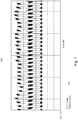
- Fig. 7 shows the characteristic curves in the above-described operation.
- the curve 711 shows the voltage at the output of the LEDset interface 17, which is modulated from 5V to 2.7V.
- Curve 731 shows the voltage at the analog-to-digital input ADC of the microcontroller. It can be seen immediately that the voltage at the analog-to-digital input ADC of the microcontroller can be easily distinguished between logic LOW and logic HIGH, if corresponding detection thresholds for the two states are set.
- Fig. 8 shows an embodiment of the interface 71 of the sensor 7.
- the fact that the voltage during "short-circuiting" the output of the LEDset interface 17 is not “shorted” to 0V but to 2.7V can during both states of the output of the LEDset interface 17 energy to the Sensor to be transmitted for operation.
- the components D1, R5 and C7 are required for the separation, buffering and filtering of the 4.5V from the LEDset interface 17.
- the components U1, R6, Q11, Q12, C6, R9 and R10 form a two-quadrant 2.7V power supply.
- the switch M1 pulls the positive output of the LEDset interface 17 not on the negative output, but on the generated 2.7V output.
- the current from the output of the LEDset interface for the 2.7V supply of the sensor 7 can be used, which drastically reduces the total power consumption and greatly increases the performance of the two-quadrant 2.7V power supply of the sensor 7.
- the power supply is constructed as a two-quadrant power supply, it can also draw power from the LEDset interface 17 and thus supply the sensor.
- Fig. 9 shows a schematic status diagram of the software which processes the signals applied to the A / D converter of the microcontroller.
- the signal is read into a logic 91 which evaluates the signal for whether it is a static or a clocked signal.
- the signal is detected as a static signal, then it is passed to a low-pass filter 93, which generates an analog voltage from the signal. This voltage is then further processed as a measured LED set current 95 in the circuit arrangement, that is, according to the voltage, a specific current at the output 13 of the circuit arrangement 1 is set.
- the signal is detected as a clocked signal, it is input to a packet decoder 92, which interprets the voltage edges and generates a corresponding bit sequence. This bit sequence is then passed on as data packet 94 for further processing.
- FIG. 13 shows a status diagram of a software packet decoder 92 that generates a digital DALI packet from the clocked signal at the second interface 17.
- step 101 the algorithm is idle and waits for the detection of an edge in the signal. If an edge is detected in step 103, then the algorithm checks in step 105 whether all values have already been queried. If this is not the case, then after a short waiting time 107, the value is read in step 109 and then in step 111 a pre-processing with respect to the Manchester coding takes place, in which the signal is coded. After processing the first value, the query jumps back into the query as to whether there are any further values that need to be processed. If further values are detected, the processing loop is run again until no further values are detected. If so, all queried values are Manchester decoded at step 102 to obtain the binary data.
- step 104 The data is then checked for validity in step 104 and discarded if errors are detected in step 106. If a valid value is detected, then the data is packaged in a DALI packet in step 108 and assigned to a DALI library in circuit 1. The data can then either be used further in the circuit arrangement 1 itself or relayed on the DALI bus 15.
Landscapes
- Physics & Mathematics (AREA)
- Life Sciences & Earth Sciences (AREA)
- General Life Sciences & Earth Sciences (AREA)
- General Physics & Mathematics (AREA)
- Geophysics (AREA)
- Circuit Arrangement For Electric Light Sources In General (AREA)
Applications Claiming Priority (1)
| Application Number | Priority Date | Filing Date | Title |
|---|---|---|---|
| DE102016226016.2A DE102016226016A1 (de) | 2016-12-22 | 2016-12-22 | SCHALTUNGSANORDNUNG ZUM BETREIBEN VON LICHTQUELLEN UND SENSOR ZUM ANSCHLIEßEN AN EINE SCHALTUNGSANORDNUNG |
Publications (3)
| Publication Number | Publication Date |
|---|---|
| EP3340742A1 true EP3340742A1 (fr) | 2018-06-27 |
| EP3340742C0 EP3340742C0 (fr) | 2024-01-31 |
| EP3340742B1 EP3340742B1 (fr) | 2024-01-31 |
Family
ID=60673538
Family Applications (1)
| Application Number | Title | Priority Date | Filing Date |
|---|---|---|---|
| EP17207197.9A Active EP3340742B1 (fr) | 2016-12-22 | 2017-12-14 | Agencement de circuit permettant le fonctionnement des sources lumineuses |
Country Status (3)
| Country | Link |
|---|---|
| US (1) | US10327301B2 (fr) |
| EP (1) | EP3340742B1 (fr) |
| DE (1) | DE102016226016A1 (fr) |
Cited By (1)
| Publication number | Priority date | Publication date | Assignee | Title |
|---|---|---|---|---|
| EP3340742B1 (fr) | 2016-12-22 | 2024-01-31 | Inventronics GmbH | Agencement de circuit permettant le fonctionnement des sources lumineuses |
Families Citing this family (1)
| Publication number | Priority date | Publication date | Assignee | Title |
|---|---|---|---|---|
| CN108541107B (zh) * | 2018-04-28 | 2024-04-12 | 赛尔富电子有限公司 | 一种照明负载异常检测装置及对应的照明系统 |
Citations (9)
| Publication number | Priority date | Publication date | Assignee | Title |
|---|---|---|---|---|
| DE102007055164A1 (de) * | 2007-11-19 | 2009-05-20 | Tridonicatco Gmbh & Co. Kg | Leuchtmittel-Betriebsgerät zu Datenausgabe |
| US20110260619A1 (en) * | 2010-03-29 | 2011-10-27 | Innosys, Inc. | LED Dimming Driver |
| DE102013221496A1 (de) * | 2013-10-23 | 2015-04-23 | Tridonic Gmbh & Co Kg | Betriebsgerät und Verfahren zum Betreiben wenigstens einer Leuchtdiode |
| WO2015067757A1 (fr) * | 2013-11-11 | 2015-05-14 | Tridonic Gmbh & Co Kg | Module de del, convertisseur de del et procédé permettant de faire fonctionner au moins une diode electroluminescente |
| DE102013226964A1 (de) * | 2013-12-20 | 2015-06-25 | Tridonic Gmbh & Co Kg | LED-Treiber zum Auslesen von Information eines LED-Moduls |
| DE102014104447A1 (de) * | 2014-03-28 | 2015-10-01 | Bag Engineering Gmbh | Elektronisches Vorschaltgerät für LED-Leuchtmittel |
| DE102014208710A1 (de) * | 2014-05-09 | 2015-11-26 | Tridonic Gmbh & Co Kg | Betriebsgerät, Leuchte und Verfahren zum Versorgen eines LED-Moduls |
| AT14580U1 (de) * | 2013-01-31 | 2016-01-15 | Tridonic Gmbh & Co Kg | Vorrichtung zum Betreiben von LEDs |
| EP3001778A1 (fr) * | 2014-09-29 | 2016-03-30 | Helvar Oy Ab | Dispositif accessoire connectable à un dispositif de commande |
Family Cites Families (13)
| Publication number | Priority date | Publication date | Assignee | Title |
|---|---|---|---|---|
| US7378805B2 (en) * | 2005-03-22 | 2008-05-27 | Fairchild Semiconductor Corporation | Single-stage digital power converter for driving LEDs |
| DE102006046489B4 (de) | 2006-09-29 | 2020-08-13 | Tridonic Gmbh & Co Kg | Verfahren und System zur drahtlosen Kommunikation zwischen mehreren Betriebsgeräten für Leuchtmittel |
| DE112008002679A5 (de) | 2007-10-15 | 2010-10-14 | Tridonicatco Gmbh & Co. Kg | Schnittstelle für Leuchtmittel -Betriebsgerät |
| US8022634B2 (en) * | 2008-02-05 | 2011-09-20 | Intersil Americas Inc. | Method and system for dimming AC-powered light emitting diode (LED) lighting systems using conventional incandescent dimmers |
| DE102008056164A1 (de) | 2008-07-29 | 2010-02-04 | Tridonicatco Gmbh & Co. Kg | Zuweisung einer Betriebsadresse an ein busfähiges Betriebsgerät für Leuchtmittel |
| WO2011123879A1 (fr) | 2010-04-09 | 2011-10-13 | Tridonic Gmbh & Co. Kg | Procédé d'excitation d'appareils d'actionnement d'éléments lumineux |
| JP6113417B2 (ja) * | 2011-04-22 | 2017-04-12 | アイリスオーヤマ株式会社 | Ledランプ |
| AT12864U1 (de) | 2011-08-17 | 2013-01-15 | Tridonic Gmbh & Co Kg | Verfahren zur adressierung von leuchtmittelbetriebsgeräten |
| US9137878B2 (en) * | 2012-03-21 | 2015-09-15 | Osram Sylvania Inc. | Dynamic lighting based on activity type |
| US9743474B2 (en) * | 2014-11-14 | 2017-08-22 | General Electric Company | Method and system for lighting interface messaging with reduced power consumption |
| DE102015112058A1 (de) | 2015-07-23 | 2017-01-26 | Itz Innovations- Und Technologiezentrum Gmbh | Modul und Betriebsgerät zum Versorgen eines LED-Leuchtmittels mit dazu passend einstellbarem Betriebsstrom |
| EP3123937B1 (fr) * | 2015-07-28 | 2019-08-28 | ams AG | Agencement de capteur biométrique et procédé de génération d'un signal biométrique |
| DE102016226016A1 (de) | 2016-12-22 | 2018-06-28 | Osram Gmbh | SCHALTUNGSANORDNUNG ZUM BETREIBEN VON LICHTQUELLEN UND SENSOR ZUM ANSCHLIEßEN AN EINE SCHALTUNGSANORDNUNG |
-
2016
- 2016-12-22 DE DE102016226016.2A patent/DE102016226016A1/de not_active Withdrawn
-
2017
- 2017-12-14 EP EP17207197.9A patent/EP3340742B1/fr active Active
- 2017-12-19 US US15/846,278 patent/US10327301B2/en active Active
Patent Citations (9)
| Publication number | Priority date | Publication date | Assignee | Title |
|---|---|---|---|---|
| DE102007055164A1 (de) * | 2007-11-19 | 2009-05-20 | Tridonicatco Gmbh & Co. Kg | Leuchtmittel-Betriebsgerät zu Datenausgabe |
| US20110260619A1 (en) * | 2010-03-29 | 2011-10-27 | Innosys, Inc. | LED Dimming Driver |
| AT14580U1 (de) * | 2013-01-31 | 2016-01-15 | Tridonic Gmbh & Co Kg | Vorrichtung zum Betreiben von LEDs |
| DE102013221496A1 (de) * | 2013-10-23 | 2015-04-23 | Tridonic Gmbh & Co Kg | Betriebsgerät und Verfahren zum Betreiben wenigstens einer Leuchtdiode |
| WO2015067757A1 (fr) * | 2013-11-11 | 2015-05-14 | Tridonic Gmbh & Co Kg | Module de del, convertisseur de del et procédé permettant de faire fonctionner au moins une diode electroluminescente |
| DE102013226964A1 (de) * | 2013-12-20 | 2015-06-25 | Tridonic Gmbh & Co Kg | LED-Treiber zum Auslesen von Information eines LED-Moduls |
| DE102014104447A1 (de) * | 2014-03-28 | 2015-10-01 | Bag Engineering Gmbh | Elektronisches Vorschaltgerät für LED-Leuchtmittel |
| DE102014208710A1 (de) * | 2014-05-09 | 2015-11-26 | Tridonic Gmbh & Co Kg | Betriebsgerät, Leuchte und Verfahren zum Versorgen eines LED-Moduls |
| EP3001778A1 (fr) * | 2014-09-29 | 2016-03-30 | Helvar Oy Ab | Dispositif accessoire connectable à un dispositif de commande |
Cited By (1)
| Publication number | Priority date | Publication date | Assignee | Title |
|---|---|---|---|---|
| EP3340742B1 (fr) | 2016-12-22 | 2024-01-31 | Inventronics GmbH | Agencement de circuit permettant le fonctionnement des sources lumineuses |
Also Published As
| Publication number | Publication date |
|---|---|
| US10327301B2 (en) | 2019-06-18 |
| US20180184496A1 (en) | 2018-06-28 |
| EP3340742C0 (fr) | 2024-01-31 |
| EP3340742B1 (fr) | 2024-01-31 |
| DE102016226016A1 (de) | 2018-06-28 |
Similar Documents
| Publication | Publication Date | Title |
|---|---|---|
| DE60118777T2 (de) | Protokollverbesserung für beleuchtungssteuernetze und kommunikationsschnittstelle hierfür | |
| DE102004002026A1 (de) | Ansteuerung von Leuchtmittel-Betriebsgeräten über einen modulierten DC-Bus | |
| EP3549233A1 (fr) | Équipement de commande comprenant un commutateur de test et un affichage d'état | |
| DE102013001194A1 (de) | LED-Modul. LED-Vorschaltvorrichtung und System aus einem LED-Modul und einer LED-Vorschaltvorrichtung | |
| EP2939505B1 (fr) | Circuit d'interface pour la transmission de signaux | |
| DE10213254A1 (de) | Lastbetriebssystem und Verfahren dazu | |
| EP3340742B1 (fr) | Agencement de circuit permettant le fonctionnement des sources lumineuses | |
| EP3235346B1 (fr) | Circuit d'alimentation, appareillage d'alimentation, système d'éclairage et procédé permettant de faire fonctionner au moins une diode électroluminescente | |
| DE102018205590B4 (de) | LEISTUNGSVERSORGUNGSVORRICHTUNG UND KOMMUNIKATIONSSYSTEM FÜR BELEUCHTUNGSSYSTEME MIT DERSELBEN, SOWIE vERFAHREN ZUR SPANNUNGSVERSORGUNG EINER ELEKTRISCHEN LAST | |
| EP2952065B1 (fr) | Dispositif et procédé servant à faire fonctionner des del | |
| EP1473976B1 (fr) | Interface pour signaux de commande digitaux ou signaux de commande par le réseau et méthode de dimensionnement d' un tel interface | |
| WO2011123963A2 (fr) | Circuit électronique pour la mesure de lumière de diodes électroluminescentes utilisées dans une lumière d'urgence | |
| WO2017157848A1 (fr) | Appareil d'exploitation très fonctionnel | |
| EP1341402A2 (fr) | Dispositif d' éclairage à module-LED | |
| EP3689112B1 (fr) | Possibilité de signalisation étendue dans un système dali | |
| DE102007047847A1 (de) | Lichtsignalanlage mit Signalgebern und einer Steuereinrichtung zum Steuern von Leuchten in den Signalgebern | |
| DE102016215568A1 (de) | Elektrisches Verbrauchsmodul für ein Kraftfahrzeug | |
| DE102007013758A1 (de) | Schnittstelle mit temperaturkompensiertem Sendezweig | |
| DE102015200128A1 (de) | Leuchtmittel-Konverter und Leuchtmittel-Modul mit Zweidraht-Kommunikation | |
| DE202019104171U1 (de) | Treiber | |
| EP3100591B1 (fr) | Détection d'un module led | |
| EP3253181B1 (fr) | Procédé pour la communication de données entre un module d'émission/réception et un module led comprenant au moins une led ou entre un module d'émission/réception et des modules led dans un branchement en série de plusieurs modules led, comprenant chacun au moins une led | |
| EP3627973B1 (fr) | Procédé de fonctionnement d'un module de consommateur électrique ainsi que système de consommateur électrique | |
| DE102016118085A1 (de) | Verfahren und sensorvorrichtung zur steuerung einer beleuchtungseinrichtung in einem beleuchtungssystem sowie beleuchtungssystem hierzu | |
| AT508809A1 (de) | Schnittstelle für ein betriebsgerät für leuchtmittel |
Legal Events
| Date | Code | Title | Description |
|---|---|---|---|
| PUAI | Public reference made under article 153(3) epc to a published international application that has entered the european phase |
Free format text: ORIGINAL CODE: 0009012 |
|
| STAA | Information on the status of an ep patent application or granted ep patent |
Free format text: STATUS: THE APPLICATION HAS BEEN PUBLISHED |
|
| AK | Designated contracting states |
Kind code of ref document: A1 Designated state(s): AL AT BE BG CH CY CZ DE DK EE ES FI FR GB GR HR HU IE IS IT LI LT LU LV MC MK MT NL NO PL PT RO RS SE SI SK SM TR |
|
| AX | Request for extension of the european patent |
Extension state: BA ME |
|
| STAA | Information on the status of an ep patent application or granted ep patent |
Free format text: STATUS: REQUEST FOR EXAMINATION WAS MADE |
|
| 17P | Request for examination filed |
Effective date: 20190102 |
|
| RBV | Designated contracting states (corrected) |
Designated state(s): AL AT BE BG CH CY CZ DE DK EE ES FI FR GB GR HR HU IE IS IT LI LT LU LV MC MK MT NL NO PL PT RO RS SE SI SK SM TR |
|
| STAA | Information on the status of an ep patent application or granted ep patent |
Free format text: STATUS: EXAMINATION IS IN PROGRESS |
|
| 17Q | First examination report despatched |
Effective date: 20200408 |
|
| RAP1 | Party data changed (applicant data changed or rights of an application transferred) |
Owner name: OSRAM GMBH |
|
| REG | Reference to a national code |
Ref country code: DE Ref legal event code: R079 Free format text: PREVIOUS MAIN CLASS: H05B0037020000 Ipc: H05B0045220000 Ref document number: 502017015801 Country of ref document: DE |
|
| RIC1 | Information provided on ipc code assigned before grant |
Ipc: H05B 45/10 20200101ALI20221129BHEP Ipc: H05B 47/10 20200101ALI20221129BHEP Ipc: H05B 45/22 20200101AFI20221129BHEP |
|
| GRAP | Despatch of communication of intention to grant a patent |
Free format text: ORIGINAL CODE: EPIDOSNIGR1 |
|
| STAA | Information on the status of an ep patent application or granted ep patent |
Free format text: STATUS: GRANT OF PATENT IS INTENDED |
|
| INTG | Intention to grant announced |
Effective date: 20230110 |
|
| GRAS | Grant fee paid |
Free format text: ORIGINAL CODE: EPIDOSNIGR3 |
|
| RAP1 | Party data changed (applicant data changed or rights of an application transferred) |
Owner name: INVENTRONICS GMBH |
|
| GRAA | (expected) grant |
Free format text: ORIGINAL CODE: 0009210 |
|
| STAA | Information on the status of an ep patent application or granted ep patent |
Free format text: STATUS: THE PATENT HAS BEEN GRANTED |
|
| AK | Designated contracting states |
Kind code of ref document: B1 Designated state(s): AL AT BE BG CH CY CZ DE DK EE ES FI FR GB GR HR HU IE IS IT LI LT LU LV MC MK MT NL NO PL PT RO RS SE SI SK SM TR |
|
| REG | Reference to a national code |
Ref country code: GB Ref legal event code: FG4D Free format text: NOT ENGLISH Ref country code: CH Ref legal event code: EP |
|
| REG | Reference to a national code |
Ref country code: DE Ref legal event code: R096 Ref document number: 502017015801 Country of ref document: DE |
|
| REG | Reference to a national code |
Ref country code: IE Ref legal event code: FG4D Free format text: LANGUAGE OF EP DOCUMENT: GERMAN |
|
| U01 | Request for unitary effect filed |
Effective date: 20240228 |
|
| U07 | Unitary effect registered |
Designated state(s): AT BE BG DE DK EE FI FR IT LT LU LV MT NL PT SE SI Effective date: 20240306 |
|
| PG25 | Lapsed in a contracting state [announced via postgrant information from national office to epo] |
Ref country code: IS Free format text: LAPSE BECAUSE OF FAILURE TO SUBMIT A TRANSLATION OF THE DESCRIPTION OR TO PAY THE FEE WITHIN THE PRESCRIBED TIME-LIMIT Effective date: 20240531 |
|
| PG25 | Lapsed in a contracting state [announced via postgrant information from national office to epo] |
Ref country code: GR Free format text: LAPSE BECAUSE OF FAILURE TO SUBMIT A TRANSLATION OF THE DESCRIPTION OR TO PAY THE FEE WITHIN THE PRESCRIBED TIME-LIMIT Effective date: 20240501 |
|
| PG25 | Lapsed in a contracting state [announced via postgrant information from national office to epo] |
Ref country code: RS Free format text: LAPSE BECAUSE OF FAILURE TO SUBMIT A TRANSLATION OF THE DESCRIPTION OR TO PAY THE FEE WITHIN THE PRESCRIBED TIME-LIMIT Effective date: 20240430 Ref country code: HR Free format text: LAPSE BECAUSE OF FAILURE TO SUBMIT A TRANSLATION OF THE DESCRIPTION OR TO PAY THE FEE WITHIN THE PRESCRIBED TIME-LIMIT Effective date: 20240131 |
|
| PG25 | Lapsed in a contracting state [announced via postgrant information from national office to epo] |
Ref country code: ES Free format text: LAPSE BECAUSE OF FAILURE TO SUBMIT A TRANSLATION OF THE DESCRIPTION OR TO PAY THE FEE WITHIN THE PRESCRIBED TIME-LIMIT Effective date: 20240131 |
|
| PG25 | Lapsed in a contracting state [announced via postgrant information from national office to epo] |
Ref country code: RS Free format text: LAPSE BECAUSE OF FAILURE TO SUBMIT A TRANSLATION OF THE DESCRIPTION OR TO PAY THE FEE WITHIN THE PRESCRIBED TIME-LIMIT Effective date: 20240430 Ref country code: NO Free format text: LAPSE BECAUSE OF FAILURE TO SUBMIT A TRANSLATION OF THE DESCRIPTION OR TO PAY THE FEE WITHIN THE PRESCRIBED TIME-LIMIT Effective date: 20240430 Ref country code: IS Free format text: LAPSE BECAUSE OF FAILURE TO SUBMIT A TRANSLATION OF THE DESCRIPTION OR TO PAY THE FEE WITHIN THE PRESCRIBED TIME-LIMIT Effective date: 20240531 Ref country code: HR Free format text: LAPSE BECAUSE OF FAILURE TO SUBMIT A TRANSLATION OF THE DESCRIPTION OR TO PAY THE FEE WITHIN THE PRESCRIBED TIME-LIMIT Effective date: 20240131 Ref country code: GR Free format text: LAPSE BECAUSE OF FAILURE TO SUBMIT A TRANSLATION OF THE DESCRIPTION OR TO PAY THE FEE WITHIN THE PRESCRIBED TIME-LIMIT Effective date: 20240501 Ref country code: ES Free format text: LAPSE BECAUSE OF FAILURE TO SUBMIT A TRANSLATION OF THE DESCRIPTION OR TO PAY THE FEE WITHIN THE PRESCRIBED TIME-LIMIT Effective date: 20240131 |
|
| PG25 | Lapsed in a contracting state [announced via postgrant information from national office to epo] |
Ref country code: PL Free format text: LAPSE BECAUSE OF FAILURE TO SUBMIT A TRANSLATION OF THE DESCRIPTION OR TO PAY THE FEE WITHIN THE PRESCRIBED TIME-LIMIT Effective date: 20240131 |
|
| PG25 | Lapsed in a contracting state [announced via postgrant information from national office to epo] |
Ref country code: PL Free format text: LAPSE BECAUSE OF FAILURE TO SUBMIT A TRANSLATION OF THE DESCRIPTION OR TO PAY THE FEE WITHIN THE PRESCRIBED TIME-LIMIT Effective date: 20240131 |
|
| PG25 | Lapsed in a contracting state [announced via postgrant information from national office to epo] |
Ref country code: SM Free format text: LAPSE BECAUSE OF FAILURE TO SUBMIT A TRANSLATION OF THE DESCRIPTION OR TO PAY THE FEE WITHIN THE PRESCRIBED TIME-LIMIT Effective date: 20240131 |
|
| PG25 | Lapsed in a contracting state [announced via postgrant information from national office to epo] |
Ref country code: CZ Free format text: LAPSE BECAUSE OF FAILURE TO SUBMIT A TRANSLATION OF THE DESCRIPTION OR TO PAY THE FEE WITHIN THE PRESCRIBED TIME-LIMIT Effective date: 20240131 |
|
| PG25 | Lapsed in a contracting state [announced via postgrant information from national office to epo] |
Ref country code: SK Free format text: LAPSE BECAUSE OF FAILURE TO SUBMIT A TRANSLATION OF THE DESCRIPTION OR TO PAY THE FEE WITHIN THE PRESCRIBED TIME-LIMIT Effective date: 20240131 |
|
| REG | Reference to a national code |
Ref country code: DE Ref legal event code: R026 Ref document number: 502017015801 Country of ref document: DE |
|
| PG25 | Lapsed in a contracting state [announced via postgrant information from national office to epo] |
Ref country code: SM Free format text: LAPSE BECAUSE OF FAILURE TO SUBMIT A TRANSLATION OF THE DESCRIPTION OR TO PAY THE FEE WITHIN THE PRESCRIBED TIME-LIMIT Effective date: 20240131 Ref country code: SK Free format text: LAPSE BECAUSE OF FAILURE TO SUBMIT A TRANSLATION OF THE DESCRIPTION OR TO PAY THE FEE WITHIN THE PRESCRIBED TIME-LIMIT Effective date: 20240131 Ref country code: RO Free format text: LAPSE BECAUSE OF FAILURE TO SUBMIT A TRANSLATION OF THE DESCRIPTION OR TO PAY THE FEE WITHIN THE PRESCRIBED TIME-LIMIT Effective date: 20240131 Ref country code: CZ Free format text: LAPSE BECAUSE OF FAILURE TO SUBMIT A TRANSLATION OF THE DESCRIPTION OR TO PAY THE FEE WITHIN THE PRESCRIBED TIME-LIMIT Effective date: 20240131 |
|
| PLBI | Opposition filed |
Free format text: ORIGINAL CODE: 0009260 |
|
| PLAB | Opposition data, opponent's data or that of the opponent's representative modified |
Free format text: ORIGINAL CODE: 0009299OPPO |
|
| PLAX | Notice of opposition and request to file observation + time limit sent |
Free format text: ORIGINAL CODE: EPIDOSNOBS2 |
|
| 26 | Opposition filed |
Opponent name: TRIDONIC GMBH & CO KG Effective date: 20241030 |
|
| R26 | Opposition filed (corrected) |
Opponent name: TRIDONIC GMBH & CO KG Effective date: 20241030 |
|
| U20 | Renewal fee for the european patent with unitary effect paid |
Year of fee payment: 8 Effective date: 20241219 |
|
| PLBB | Reply of patent proprietor to notice(s) of opposition received |
Free format text: ORIGINAL CODE: EPIDOSNOBS3 |
|
| PG25 | Lapsed in a contracting state [announced via postgrant information from national office to epo] |
Ref country code: MC Free format text: LAPSE BECAUSE OF FAILURE TO SUBMIT A TRANSLATION OF THE DESCRIPTION OR TO PAY THE FEE WITHIN THE PRESCRIBED TIME-LIMIT Effective date: 20240131 |
|
| REG | Reference to a national code |
Ref country code: CH Ref legal event code: PL |
|
| PG25 | Lapsed in a contracting state [announced via postgrant information from national office to epo] |
Ref country code: CH Free format text: LAPSE BECAUSE OF NON-PAYMENT OF DUE FEES Effective date: 20241231 |
|
| PG25 | Lapsed in a contracting state [announced via postgrant information from national office to epo] |
Ref country code: IE Free format text: LAPSE BECAUSE OF NON-PAYMENT OF DUE FEES Effective date: 20241214 |
|
| PGFP | Annual fee paid to national office [announced via postgrant information from national office to epo] |
Ref country code: GB Payment date: 20251218 Year of fee payment: 9 |
|
| U20 | Renewal fee for the european patent with unitary effect paid |
Year of fee payment: 9 Effective date: 20251222 |
|
| PLBP | Opposition withdrawn |
Free format text: ORIGINAL CODE: 0009264 |
|
| REG | Reference to a national code |
Ref country code: CH Ref legal event code: L10 Free format text: ST27 STATUS EVENT CODE: U-0-0-L10-L00 (AS PROVIDED BY THE NATIONAL OFFICE) Effective date: 20260423 |