EP3344390B1 - Dispositif de filtration en profondeur pour la séparation de phases d'échantillon - Google Patents
Dispositif de filtration en profondeur pour la séparation de phases d'échantillon Download PDFInfo
- Publication number
- EP3344390B1 EP3344390B1 EP16763679.4A EP16763679A EP3344390B1 EP 3344390 B1 EP3344390 B1 EP 3344390B1 EP 16763679 A EP16763679 A EP 16763679A EP 3344390 B1 EP3344390 B1 EP 3344390B1
- Authority
- EP
- European Patent Office
- Prior art keywords
- phase
- separator
- biological sample
- pressure
- separation
- Prior art date
- Legal status (The legal status is an assumption and is not a legal conclusion. Google has not performed a legal analysis and makes no representation as to the accuracy of the status listed.)
- Active
Links
Images




Classifications
-
- B—PERFORMING OPERATIONS; TRANSPORTING
- B01—PHYSICAL OR CHEMICAL PROCESSES OR APPARATUS IN GENERAL
- B01D—SEPARATION
- B01D15/00—Separating processes involving the treatment of liquids with solid sorbents; Apparatus therefor
- B01D15/08—Selective adsorption, e.g. chromatography
- B01D15/10—Selective adsorption, e.g. chromatography characterised by constructional or operational features
-
- G—PHYSICS
- G01—MEASURING; TESTING
- G01N—INVESTIGATING OR ANALYSING MATERIALS BY DETERMINING THEIR CHEMICAL OR PHYSICAL PROPERTIES
- G01N33/00—Investigating or analysing materials by specific methods not covered by groups G01N1/00 - G01N31/00
- G01N33/48—Biological material, e.g. blood, urine; Haemocytometers
- G01N33/483—Physical analysis of biological material
- G01N33/487—Physical analysis of biological material of liquid biological material
- G01N33/49—Blood
- G01N33/491—Blood by separating the blood components
-
- A—HUMAN NECESSITIES
- A61—MEDICAL OR VETERINARY SCIENCE; HYGIENE
- A61B—DIAGNOSIS; SURGERY; IDENTIFICATION
- A61B5/00—Measuring for diagnostic purposes; Identification of persons
- A61B5/15—Devices for taking samples of blood
- A61B5/150007—Details
- A61B5/150015—Source of blood
- A61B5/150022—Source of blood for capillary blood or interstitial fluid
-
- A—HUMAN NECESSITIES
- A61—MEDICAL OR VETERINARY SCIENCE; HYGIENE
- A61B—DIAGNOSIS; SURGERY; IDENTIFICATION
- A61B5/00—Measuring for diagnostic purposes; Identification of persons
- A61B5/15—Devices for taking samples of blood
- A61B5/150007—Details
- A61B5/150343—Collection vessels for collecting blood samples from the skin surface, e.g. test tubes, cuvettes
-
- A—HUMAN NECESSITIES
- A61—MEDICAL OR VETERINARY SCIENCE; HYGIENE
- A61B—DIAGNOSIS; SURGERY; IDENTIFICATION
- A61B5/00—Measuring for diagnostic purposes; Identification of persons
- A61B5/15—Devices for taking samples of blood
- A61B5/150007—Details
- A61B5/150358—Strips for collecting blood, e.g. absorbent
-
- B—PERFORMING OPERATIONS; TRANSPORTING
- B01—PHYSICAL OR CHEMICAL PROCESSES OR APPARATUS IN GENERAL
- B01L—CHEMICAL OR PHYSICAL LABORATORY APPARATUS FOR GENERAL USE
- B01L3/00—Containers or dishes for laboratory use, e.g. laboratory glassware; Droppers
- B01L3/50—Containers for the purpose of retaining a material to be analysed, e.g. test tubes
- B01L3/502—Containers for the purpose of retaining a material to be analysed, e.g. test tubes with fluid transport, e.g. in multi-compartment structures
-
- B—PERFORMING OPERATIONS; TRANSPORTING
- B01—PHYSICAL OR CHEMICAL PROCESSES OR APPARATUS IN GENERAL
- B01L—CHEMICAL OR PHYSICAL LABORATORY APPARATUS FOR GENERAL USE
- B01L3/00—Containers or dishes for laboratory use, e.g. laboratory glassware; Droppers
- B01L3/50—Containers for the purpose of retaining a material to be analysed, e.g. test tubes
- B01L3/502—Containers for the purpose of retaining a material to be analysed, e.g. test tubes with fluid transport, e.g. in multi-compartment structures
- B01L3/5023—Containers for the purpose of retaining a material to be analysed, e.g. test tubes with fluid transport, e.g. in multi-compartment structures with a sample being transported to, and subsequently stored in an absorbent for analysis
-
- B—PERFORMING OPERATIONS; TRANSPORTING
- B01—PHYSICAL OR CHEMICAL PROCESSES OR APPARATUS IN GENERAL
- B01L—CHEMICAL OR PHYSICAL LABORATORY APPARATUS FOR GENERAL USE
- B01L2200/00—Solutions for specific problems relating to chemical or physical laboratory apparatus
- B01L2200/02—Adapting objects or devices to another
- B01L2200/026—Fluid interfacing between devices or objects, e.g. connectors, inlet details
-
- B—PERFORMING OPERATIONS; TRANSPORTING
- B01—PHYSICAL OR CHEMICAL PROCESSES OR APPARATUS IN GENERAL
- B01L—CHEMICAL OR PHYSICAL LABORATORY APPARATUS FOR GENERAL USE
- B01L2200/00—Solutions for specific problems relating to chemical or physical laboratory apparatus
- B01L2200/06—Fluid handling related problems
- B01L2200/0647—Handling flowable solids, e.g. microscopic beads, cells, particles
- B01L2200/0652—Sorting or classification of particles or molecules
-
- B—PERFORMING OPERATIONS; TRANSPORTING
- B01—PHYSICAL OR CHEMICAL PROCESSES OR APPARATUS IN GENERAL
- B01L—CHEMICAL OR PHYSICAL LABORATORY APPARATUS FOR GENERAL USE
- B01L2300/00—Additional constructional details
- B01L2300/04—Closures and closing means
- B01L2300/041—Connecting closures to device or container
- B01L2300/042—Caps; Plugs
-
- B—PERFORMING OPERATIONS; TRANSPORTING
- B01—PHYSICAL OR CHEMICAL PROCESSES OR APPARATUS IN GENERAL
- B01L—CHEMICAL OR PHYSICAL LABORATORY APPARATUS FOR GENERAL USE
- B01L2300/00—Additional constructional details
- B01L2300/04—Closures and closing means
- B01L2300/046—Function or devices integrated in the closure
- B01L2300/048—Function or devices integrated in the closure enabling gas exchange, e.g. vents
-
- B—PERFORMING OPERATIONS; TRANSPORTING
- B01—PHYSICAL OR CHEMICAL PROCESSES OR APPARATUS IN GENERAL
- B01L—CHEMICAL OR PHYSICAL LABORATORY APPARATUS FOR GENERAL USE
- B01L2300/00—Additional constructional details
- B01L2300/06—Auxiliary integrated devices, integrated components
- B01L2300/0609—Holders integrated in container to position an object
-
- B—PERFORMING OPERATIONS; TRANSPORTING
- B01—PHYSICAL OR CHEMICAL PROCESSES OR APPARATUS IN GENERAL
- B01L—CHEMICAL OR PHYSICAL LABORATORY APPARATUS FOR GENERAL USE
- B01L2300/00—Additional constructional details
- B01L2300/06—Auxiliary integrated devices, integrated components
- B01L2300/0681—Filter
-
- B—PERFORMING OPERATIONS; TRANSPORTING
- B01—PHYSICAL OR CHEMICAL PROCESSES OR APPARATUS IN GENERAL
- B01L—CHEMICAL OR PHYSICAL LABORATORY APPARATUS FOR GENERAL USE
- B01L2300/00—Additional constructional details
- B01L2300/08—Geometry, shape and general structure
- B01L2300/0832—Geometry, shape and general structure cylindrical, tube shaped
- B01L2300/0838—Capillaries
-
- B—PERFORMING OPERATIONS; TRANSPORTING
- B01—PHYSICAL OR CHEMICAL PROCESSES OR APPARATUS IN GENERAL
- B01L—CHEMICAL OR PHYSICAL LABORATORY APPARATUS FOR GENERAL USE
- B01L2300/00—Additional constructional details
- B01L2300/08—Geometry, shape and general structure
- B01L2300/0861—Configuration of multiple channels and/or chambers in a single devices
- B01L2300/087—Multiple sequential chambers
-
- B—PERFORMING OPERATIONS; TRANSPORTING
- B01—PHYSICAL OR CHEMICAL PROCESSES OR APPARATUS IN GENERAL
- B01L—CHEMICAL OR PHYSICAL LABORATORY APPARATUS FOR GENERAL USE
- B01L2300/00—Additional constructional details
- B01L2300/12—Specific details about materials
- B01L2300/123—Flexible; Elastomeric
-
- B—PERFORMING OPERATIONS; TRANSPORTING
- B01—PHYSICAL OR CHEMICAL PROCESSES OR APPARATUS IN GENERAL
- B01L—CHEMICAL OR PHYSICAL LABORATORY APPARATUS FOR GENERAL USE
- B01L2300/00—Additional constructional details
- B01L2300/14—Means for pressure control
-
- B—PERFORMING OPERATIONS; TRANSPORTING
- B01—PHYSICAL OR CHEMICAL PROCESSES OR APPARATUS IN GENERAL
- B01L—CHEMICAL OR PHYSICAL LABORATORY APPARATUS FOR GENERAL USE
- B01L2300/00—Additional constructional details
- B01L2300/16—Surface properties and coatings
- B01L2300/161—Control and use of surface tension forces, e.g. hydrophobic, hydrophilic
-
- B—PERFORMING OPERATIONS; TRANSPORTING
- B01—PHYSICAL OR CHEMICAL PROCESSES OR APPARATUS IN GENERAL
- B01L—CHEMICAL OR PHYSICAL LABORATORY APPARATUS FOR GENERAL USE
- B01L2400/00—Moving or stopping fluids
- B01L2400/04—Moving fluids with specific forces or mechanical means
- B01L2400/0403—Moving fluids with specific forces or mechanical means specific forces
- B01L2400/0406—Moving fluids with specific forces or mechanical means specific forces capillary forces
-
- B—PERFORMING OPERATIONS; TRANSPORTING
- B01—PHYSICAL OR CHEMICAL PROCESSES OR APPARATUS IN GENERAL
- B01L—CHEMICAL OR PHYSICAL LABORATORY APPARATUS FOR GENERAL USE
- B01L2400/00—Moving or stopping fluids
- B01L2400/04—Moving fluids with specific forces or mechanical means
- B01L2400/0475—Moving fluids with specific forces or mechanical means specific mechanical means and fluid pressure
- B01L2400/0481—Moving fluids with specific forces or mechanical means specific mechanical means and fluid pressure squeezing of channels or chambers
-
- B—PERFORMING OPERATIONS; TRANSPORTING
- B01—PHYSICAL OR CHEMICAL PROCESSES OR APPARATUS IN GENERAL
- B01L—CHEMICAL OR PHYSICAL LABORATORY APPARATUS FOR GENERAL USE
- B01L2400/00—Moving or stopping fluids
- B01L2400/04—Moving fluids with specific forces or mechanical means
- B01L2400/0475—Moving fluids with specific forces or mechanical means specific mechanical means and fluid pressure
- B01L2400/0487—Moving fluids with specific forces or mechanical means specific mechanical means and fluid pressure fluid pressure, pneumatics
- B01L2400/049—Moving fluids with specific forces or mechanical means specific mechanical means and fluid pressure fluid pressure, pneumatics vacuum
Definitions
- the present disclosure relates generally to a device and method for separating higher and lower density fractions of a fluid sample and, more particularly, the present disclosure relates to a device and method for rapidly separating higher and lower density fractions of a fluid sample without the need for a centrifuge or other high-cost equipment.
- Diagnostic tests may require separation of a patient's whole blood sample into components, such as serum or plasma (the lower density phase components), and particles and aggregates such as red and white blood cells and platelets (the higher density phase components).
- components such as serum or plasma (the lower density phase components), and particles and aggregates such as red and white blood cells and platelets (the higher density phase components).
- Samples of whole blood are typically collected via venipuncture through a cannula or needle attached to a syringe or an evacuated blood collection tube. After collection, separation of the blood into serum or plasma and blood cells is typically accomplished by centrifugation of the whole blood. More recently, there has been an effort to separate plasma using microfluidics. However, these approaches are limited by requirements of dilution and the total volume of blood that can be processed.
- Another common method used for processing micro samples of blood is the lateral flow separation method wherein a blood sample moves through a strip of filter material in a lateral direction.
- the total surface area to volume requirements of the material limits the total volume of blood that can be processed.
- Another technique for separating plasma from a whole blood sample is simple filtration which allows the blood sample to flow via capillary forces through a filter wherein the filter includes pore sizes which are smaller than the size of the cellular particles or red blood cells.
- This method is commonly referred to as conventional size exclusion filtration.
- the filter traps the cellular particles or red blood cells so as to separate these particles/cells from the serum or plasma portion.
- one drawback to this method is that the filter can become blocked, thus hindering movement of the whole blood sample therethrough and, thus, slowing and/or reducing the collection of the plasma portion of the sample.
- WO 2012/122088 A1 , WO 93/11221 A1 and US 2006/029923 A1 describe separation devices including a filter elements made up of layers of varying porosities.
- the present disclosure provides a biological fluid collection device, such as a blood collection device, that is adapted to receive a multi-component blood sample having a cellular portion and a plasma portion and quickly, efficiently, and cost-effectively separate the plasma portion from the sample.
- a biological fluid collection device such as a blood collection device
- a device for separation of a biological sample into a first phase and a second phase includes a container including an inlet and an outlet wherein the inlet is configured for receiving the biological sample.
- the device further includes a separator located within the container for separating the biological sample into the first phase and the second phase.
- the separator includes a series of filters of variable pore sizes or multiple grades of fibrous filters to progressively filter out different cell types to yield a clean first phase and a member for creating a pressure gradient across the separator to increase a rate of movement of the biological sample through the separator such that the first phase exits the separator prior to the second phase.
- the separator includes at least one fibrous filter with a chaotic fibrous structure that slows particles located within the second phase to further slow the flow of the second phase and increase a flow of the first phase through the separator.
- the biological sample can move through the container in a vertical direction and the separator includes an open cell foam positioned adjacent the inlet.
- the device further includes a cell filter located after the separator wherein the cell filter is configured to block the second phase from movement therethrough and exiting through the outlet.
- a dry anticoagulant material can be deposited on the separator.
- the separator can also be treated to include at least one of a hydrophobic, hydrophilic, or reactive internal pore surface. Additionally, the separator can be treated to avoid analyte bias. This treatment can be either additive coatings that act to block analytes from sticking to a surface or chemical surface modifications.
- the pressure gradient can include a first pressure located at an inlet of the container and a second pressure located at the outlet of the container and wherein the first pressure is greater than the second pressure.
- the member for creating the pressure gradient can include a pressure regulator for controlling the pressure gradient to generate a desired pressure profile. Depending upon which device is being used to create the pressure gradient, the pressure gradient can be one of, or a combination of, a constant, increasing, or decreasing pressure.
- a device for separation of a biological sample into a first phase and a second phase includes a container including at least a first portion having a first diameter, a second portion having a second diameter, and a third portion having a third diameter, an inlet located adjacent the first portion wherein the inlet is configured for receiving the biological sample, and an outlet located adjacent the third portion, wherein the second portion is located between the first and third portion.
- the device further includes a separator located within the container for separating the biological sample into the first phase and the second phase and a device for creating a pressure gradient across the separator to increase a rate of movement of the biological sample through the separator such that the first phase exits the separator and the outlet prior to the second phase, and wherein the first, second, and third diameters progressively decrease in size.
- the biological sample moves through the container in a vertical direction and at least one of the first, second, and third portions has a conical or tapered structure.
- the device can also include a narrow feed channel having a diameter which is less than the first diameter of the first portion.
- a device for separation of a biological sample into a first phase and a second phase includes a holder including an inlet and an outlet.
- the inlet is configured for receiving the biological sample.
- the device further includes at least one lateral flow strip cooperating with the holder for separating the biological sample into the first phase and the second phase and a member for creating a pressure gradient across the lateral flow strip to increase a rate of movement of the biological sample through the lateral flow strip such that the first phase exits the flow strip and the outlet prior to the second phase.
- the at least one lateral flow strip can comprise a plurality of lateral flow strips stacked one upon another.
- the lateral flow strips can have a trapezoidal shape having a large base and a small base wherein the large base is positioned adjacent the inlet of the holder and the small base is positioned adjacent the outlet of the holder.
- a device for the collection and separation of a biological sample into a first phase and a second phase includes a capillary tube configured for receiving the biological sample via capillary pressure, a container associated with the capillary tube wherein the container includes an outlet, a separator located within the container for separating the biological sample into the first phase and the second phase, and a member associated with the container outlet for creating a pressure gradient across the separator to increase a rate of movement of the biological sample through the separator to facilitate separation of the first phase from the second phase.
- the separator can include at least one filter formed of a fibrous material.
- the member for creating the pressure gradient can comprise a syringe.
- the container can also comprise a separation chamber and a first phase collection chamber and wherein after separation of the sample and collection of the first phase into the collection chamber, the collection chamber can be removed from the separation chamber.
- the collection chamber can include a luer lock for connecting the collection chamber to the syringe and after removal of the collection chamber from the separation chamber, the syringe can be used to force the first phase out of the collection chamber and into a separate container for diagnostic testing.
- a device for the collection of a biological sample and separation of the biological sample into a first phase and a second phase includes a collection chamber having an inlet for collecting the biological sample via venous pressure, a separation chamber associated with the collection chamber, a separator located within the separation chamber for separating the biological sample into the first phase and the second phase, a capillary tube associated with the separation chamber wherein the capillary tube includes a first end configured for receiving the first phase and a second end, and a member associated with the second end of the capillary tube for creating a pressure gradient across the separator to increase a rate of movement of the biological sample through the separator to facilitate separation of the first phase from the second phase.
- the separator can comprise at least one filter formed of a fibrous material, and the member for creating the pressure gradient can comprise a syringe.
- the capillary tube is separable from the separation chamber such that after separation of the sample and collection of the first phase into the capillary tube, the capillary tube can be removed from the separation chamber.
- the collection chamber can include a luer lock for connecting the collection chamber to a biological collection system, and the second end of the capillary tube can include a luer lock for connecting to the syringe.
- a device for the collection of a biological sample and separation of the biological sample into a first phase and a second phase includes a collection chamber having an inlet for collecting the biological sample via venous pressure, a separation chamber associated with the collection chamber, a separator located within the separation chamber for separating the biological sample into the first phase and the second phase, a cannula having a first end associated with the separation chamber, and a vacuum tube associated with the separation chamber via a second end of the cannula.
- the vacuum tube can be configured for applying a pressure gradient across the separator to increase a rate of movement of the biological sample through the separator to facilitate separation of the first phase from the second phase and to cause the first phase to enter into the vacuum tube via the cannula.
- the separator can comprise at least one filter formed of a fibrous material.
- the collection chamber and the separation chamber are separable from the vacuum tube such that after separation of the sample and collection of the first phase into the vacuum tube, the collection chamber and separation chamber can be removed from the vacuum tube.
- the collection chamber can include a luer lock for connecting the collection chamber to a biological collection system.
- a device for the collection of a biological sample and separation of the biological sample into a first phase and a second phase includes a sample collection chamber having an inlet for collecting the biological sample, a separation chamber associated with the sample collection chamber, a separator located within the separation chamber for separating the biological sample into the first phase and the second phase, a first phase collection chamber having a first end associated with the separation chamber, and a vacuum tube associated with the first phase collection chamber.
- the vacuum tube is configured for applying a pressure gradient across the separator to increase a rate of movement of the biological sample through the separator to facilitate separation of the first phase from the second phase and to cause the first phase to enter into the first phase collection chamber.
- the vacuum tube can enclose at least a portion of the first phase collection chamber.
- the device can further include a vented closure associated with a second end of the first phase collection chamber. This vented closure is configured for providing fluid communication between the vacuum tube and the first phase collection chamber and to prevent collected first phase to exit the collection chamber and to enter the vacuum tube (air pass - liquid stops at this vented tip cap).
- the vented closure can comprise a removable vented tip cap (air pass - liquid stops).
- the first phase collection chamber can include a flexible membrane such that upon removal of the tip cap, application of a squeezing force to the flexible membrane expels the first phase out of the device.
- the vented closure can comprise a flexible member including apertures extending therethrough.
- the first phase collection chamber is removable from the sample collection chamber such that upon removal of the first phase collection chamber from the sample collection chamber, application of a squeezing force to the flexible member expels the first phase out of the device.
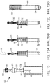
- Figs. 1 and 2A-2D show a device, generally indicated as 2, including a container 4, and a method for the sequential separation of a biological sample, such as a whole blood sample 10, into a first phase or plasma phase 14 and a second phase or cellular phase 16 using chromatographic depth filtration in accordance with the invention.
- Whole blood includes four components: red blood cells, white blood cells, plasma, and platelets.
- the liquid component of blood is plasma, which comprises a mixture of water, sugar, fat, protein, and salts.
- red blood cells 22 and other cellular particles, i.e., white blood cells, platelets, and the like 23 interact with fibers 24 either by colliding or wrapping around the fibers 24.
- This interaction slows the cellular particles 22, 23 within the cellular phase 16, whereas the plasma phase 14 moves ahead at a faster rate.
- a cell free plasma front or phase 14 is produced ahead of the cellular phase 16.
- This leading plasma front or phase 14 is then collected in a container 50 as it exits the separator 30, as shown in Fig. 2D , and sent for diagnostic testing.
- a pressure gradient 40 can be applied across the separator 30 to increase a rate of movement of the biological sample 12 through the separator 30 such that the first phase 14 moves through and exits the separator 30 prior to the second phase 16.
- the device 2 for separation of the biological sample 10 into a first phase 14 and a second phase 16 includes a container 4 including an inlet 6 and an outlet 8 wherein the inlet 6 is configured for receiving the biological sample 10.
- the device 2 further includes the separator 30 located within the container 4 for separating the biological sample 10 into the first phase 14 and the second phase 16.
- the separator 30 can include a series of filters 32.
- At least one of the filters 32 is a fibrous filter having a chaotic fibrous structure that slows and traps the red blood cells and cellular particles 22, 23 located within the second phase 16 to further slow the flow of the second phase 16 and increase the flow of the first phase 14 through the separator.
- the fibrous structure of the separator 30 is designed to slow down the flow of the blood cells by acting as flow obstacles which allow the plasma/serum or the first phase 14 to move faster through the separator 30 and therefore separate toward the front of the sample flow.
- the series of filters 32 can have the same porosity, as shown in Fig. 3 . According to the invention, as shown in Figs.
- the separator 30 or series of filters 32 can have variable pore sizes through which the biological sample 10 moves in a vertical or descending direction wherein the pore size decreases in a downward direction D.
- the series of filters 32 includes an open cell foam 34 positioned adjacent the inlet 6, a fibrous filter layer 35, and a cell capture filter 36 located after the separator 30 wherein the cell capture filter 36 is configured to block the second phase 16 from movement therethrough and exiting through the outlet 8.
- the separator 30 can include multiple stages filled with different grades of filters having variable pore sizes 37, 38, 39 to progressively filter out different cell types to yield a clean first phase 14.
- the device further includes a member for creating a pressure gradient 40 across the separator 30 and is provided to increase a rate of movement of the biological sample 12 through the separator 30 such that the first phase 14 exits the separator 30 prior to the second phase 16.
- the pressure gradient 40 can include a first pressure P1 located at the inlet 6 of the container 4 and a second pressure P2 located at the outlet 8 of the container 4 and wherein the first pressure P1 is greater than the second pressure P2.
- the member for creating the pressure gradient can include a pressure regulator (not shown) for controlling the pressure gradient to generate a desired pressure profile. As shown in Figs. 10A-10C and discussed in further detail below, depending upon which device is being used to create the pressure gradient 40, the pressure gradient 40 can be one of a constant, increasing, or decreasing pressure.
- the separator 30 can include a dry anticoagulant material deposited thereon. This can be done by a technique wherein the separator material is soaked in a liquid solution of the anticoagulant of desired concentration and then evaporating the liquid. In a similar way, the separation material can be treated to include at least one of a hydrophobic, hydrophilic, or reactive internal pore surface.
- the separator can be treated to avoid analyte bias.
- Analyte bias is the difference in measured value of analyte from a control value. Generally, biases occur because of analyte sticking to a surface, analytes leaching from the surface, introduction of other components interfering with the measurement, or activation of biological processes.
- the material of the separator 30 can be treated. This treatment generally falls into two categories: additive coatings that act to block analytes from sticking to a surface, and chemical surface modifications.
- Additive coatings can include, but are not limited to the following: (1) proteins like bovine serum albumin (BSA), casein, or non-fat milk; (2) surfactants such as polysorbate 20 (Tween 20) and organosilicone (L-720); (3) polymers and copolymers such as polyethylene glycol (PEG), polyvinyl alcohol (PVA), and polyvinylpyrrolidone (PVP); (4) carbohydrates such as dextran and glycosamino glycans like heparin; and (5) a cell membrane mimicking polymer like Lipidure, 2-methacryloyloxy ethyl phosphorylcholine.
- BSA bovine serum albumin
- Tween 20 organosilicone
- L-720 organosilicone
- polymers and copolymers such as polyethylene glycol (PEG), polyvinyl alcohol (PVA), and polyvinylpyrrolidone (PVP); (4) carbohydrates such as dextran and glycosamino gly
- Chemical surface modifications can include, but are not limited to the following: (1) gas plasma treatment; (2) chemical bonding of polyethylene glycol (PEG) or other polymers to achieve a desired hydrophobicity or hydrophilicity; (3) chemical modification of the surface to introduce hydrophilic groups like ethylene glycol, or hydrophobic groups, such as long carbon chains; and (4) vapor deposition of a substance such as parylene. It can be appreciated that combinations of any of the above materials may be used to achieve the desired properties to minimize analyte bias for a specific analyte or group of analytes. In order to address the broadest range of analytes, a material/treatment combination resulting in a hydrophilic, neutral surface is targeted; however, the other treatments can be used for addressing specific analytes.
- Figs. 6A-6B and 7A-7B show a device, generally indicated as 102 for separation of a biological sample 110 into a first phase 114 and a second phase 116 wherein a container 104 has a tapered, stepped, or conical structure which improves the separation time of the biological sample 110 and results in an increased surface area at an inlet 106 which allows for processing of a large volume of the biological sample 110.
- Fig. 5 also shows a stepped configuration for the container.
- the device 102 includes a container 104 having a first portion 160 having a first diameter D1, a second portion 162 having a second diameter D2, and a third portion 164 having a third diameter D3.
- the device 102 further includes the inlet 106 located adjacent the first portion 160 wherein the inlet 106 is configured for receiving the biological sample 110.
- An outlet 108 is located adjacent the third portion 164 and the second portion 162 is located between the first portion 160 and third portion 164.
- the first D1, second D2, and third D3 diameters can progressively decrease in size in order to form a tapered, stepped, or conical structure which will improve the separation time of plasma. It can be appreciated that the stepped design is not limited to three different diameters but rather can have multiple diameters moving in a decreasing size from the inlet to the outlet of the container, approaching a conical shape.
- the device further includes a separator 130 located within the container for separating the biological sample into the first phase 114 and the second phase 116.
- the particular structures shown in Figs 5 , 6A, and 6B help in processing a large volume of biological fluid initially by reducing the overall resistance as well as avoiding clogging of the separator 130.
- the separator 130 can comprise one or more series of filters 132 having variable or decreasing pore sizes and/or multiple stages filled with different grades of filters 132.
- the device 102 further includes a member for creating a pressure gradient 140 across the separator 130 to increase a rate of movement of the biological sample 110 through the separator 130 such that the first phase 114 exits the separator 130 prior to the second phase 116.
- the pressure gradient 140 can include a first pressure P1 located at the inlet 106 of the container 104 and a second pressure P2 located at the outlet 108 of the container 104.
- the first pressure P1 is greater than the second pressure P2 to facilitate movement of the biological sample 110 through the separator 130.
- the member for creating the pressure gradient 140 can be one of several devices discussed in detail below.
- the device can also include a narrow feed channel 170 having a diameter D4 which is less than the first diameter D1 of the first portion 160.
- a narrow feed channel 170 to introduce the biological sample 110 into the device 102, there is always a column of the sample in the channel and, thus, the chance of air entering the system, as shown by arrow 172 in Fig. 7A , is minimized. This allows the device 102 to be held at any angle avoiding any orientation dependence in the system.
- Figs. 8 and 9 show a device, generally indicated as 202 for separation of a biological sample 210 into a first phase 214 and a second phase 216.
- the device 202 includes a holder 205 including an inlet 206 and an outlet 208.
- the inlet 206 is configured for receiving the biological sample 210.
- the device 202 further includes a separator 230 in the form of at least one lateral flow strip 232 cooperating with the holder 205 for separating the biological sample 210 into the first phase 214 and the second phase 216.
- a member for creating a pressure gradient 240 across the lateral flow strip 232 is provided to increase a rate of movement of the biological sample 210 through in a lateral direction L through the lateral flow strip 232 such that the first phase 214 exits the flow strip 232 and the outlet 208 prior to the second phase 216.
- a single strip is limited by how much volume it can process in the lateral direction. Accordingly, in order to process larger volumes of samples, as shown in Fig. 9 , the separator 230 can comprise a plurality of lateral flow strips 232 stacked one upon another.
- the lateral flow strips 232 can have a trapezoidal shape having a large base 244 and a small base 246 wherein the large base 244 is positioned adjacent the inlet 206 of the holder 205, and the small base 246 is positioned adjacent the outlet of the holder 205.
- Figs. 10A-10C show different modes for the driving pressure gradients 40, 140, 204 for facilitating the separation of the biological samples 10, 110, 210 as discussed in the above arrangements.
- the pressure gradient can be constant, increasing, decreasing, or any combination thereof.
- the relevant pressure modes for a passive device would include a decreasing pressure for collection tubes 42, such as shown in Fig. 10A or an increasing pressure mode, for example when using a syringe 44, as shown in Fig. 10B .
- a third mode, as shown in Fig. 10C could involve a pressure regulator 46 to generate a desired pressure profile for separating plasma or a first phase 14. This can be used in a core lab for separating plasma on the analyzer directly.
- Fig. 11 shows a device, generally indicated as 302, and Figs. 11A-11D which show a sequential method for the collection and separation of a biological sample 310 into a first phase 314 and a second phase 316.
- the device 302 includes a capillary tube 350 configured for receiving the biological sample 310 via capillary pressure.
- a separation container 352 is associated with the capillary tube 350.
- the container 352 includes an outlet 354.
- a separator 330 is located within the separation container 352 for separating the biological sample 310 into the first phase 314 and the second phase 316. It can be appreciated that the separator 330 can comprise a plurality of filters or be formed of a fibrous filter material having any of the characteristics discussed in detail above.
- a member such as a syringe 360, is associated with the container outlet 354 for creating a pressure gradient across the separator 330 to increase a rate of movement of the biological sample 310 through the separator 330 to facilitate separation of the first phase 314 from the second phase 316.
- the container 352 can further include a first phase collection chamber 356.
- a luer lock 362 can be provided at the outlet 354 of the container 352 adjacent the first phase collection chamber 356 for connecting the collection chamber 356 to the syringe 360.
- the first phase collection chamber 356 can be removably attached with the separation container 352 so that after separation of the sample 310 and collection of the first phase 314 into the collection chamber 356, the collection chamber 356 can be removed from the separation chamber 352.
- a biological sample 310 such as blood
- a syringe 360 is attached to the outlet 354 of the device 302.
- a plunger 364 is then pulled or withdrawn, as shown by arrow "W" to apply a drawing force on the sample 310 to pull the sample 310 through the separator 330 for separating the first phase 314 or plasma from the sample 310.
- the first phase collection chamber 356 is separated from the separation chamber 352, as shown by arrow S in Fig. 11C .
- the first phase 314 is now ready to be transferred to a diagnostic testing device. This transference can be accomplished by pressing the plunger 364, as shown by arrow E in Fig. 11D , to eject the first phase 314.
- Fig. 12 shows a device, generally indicated as 402, and Figs. 12A-12D which show a sequential method for the collection and separation of a biological sample 410 into a first phase 414 and a second phase 416.
- the device 402 includes a collection chamber 470 having an inlet 472 for collecting the biological sample 410 via venous pressure.
- a separation chamber 474 is associated with the collection chamber 470 and a separator 430 is located within the separation chamber 474 for separating the biological sample 410 into the first phase 414 and the second phase 416.
- a capillary tube 476 is associated with the separation chamber 474 wherein the capillary tube 476 includes a first end 477 configured for receiving the first phase 414.
- the capillary tube also includes a second end 478.
- a member such as a syringe 460, can be associated with the second end 478 of the capillary tube 476 for creating a pressure gradient across the separator 430 to increase a rate of movement of the biological sample 410 through the separator 430 to facilitate separation of the first phase 414 from the second phase 416.
- the collection chamber 470 can include a luer lock 466 for connecting the collection chamber to a biological collection system or blood collection system well known in the art.
- the second end of the capillary tube 476 can include a luer lock 462 for connecting to the syringe 460.
- the separator 430 can comprise a plurality or stack of filter elements and/or can include one or more filters formed of a fibrous material as discussed in detail above.
- the capillary tube 476 is separable from the separation chamber 474 such that after separation of the sample 410 and collection of the first phase 414 into the capillary tube 476, the capillary tube 476 can be removed from the separation chamber 474.
- the biological sample 410 such as blood
- a syringe 460 is attached to the outlet 478 of the capillary tube 476 via luer lock 462.
- the plunger 464 is then pulled or withdrawn, as shown by arrow W to apply a drawing force on the sample 410 to pull the sample 410 through the separator 430 for separating the first phase 414 or plasma from the sample 410.
- the capillary tube 476 is separated from the separation chamber 474, as shown by arrow S in Fig. 12C .
- the first phase 414 is now ready to be transferred to a diagnostic testing device. This transference can be accomplished by pressing the plunger 464, as shown by arrow E in Fig. 12D , to eject the first phase 414.
- Fig.13 shows a device, generally indicated as 502, and Figs. 13A-13D which show a sequential method for the collection and separation of a biological sample 510 into a first phase 514 and a second phase 516 using a venous biological sample, such as a venous blood sample with the separation device as part of the sample collection device to directly collect the first phase 514 or plasma directing into an evacuated tube.
- the device 502 includes a collection chamber 570 having an inlet 572 for collecting the biological sample 510 via venous pressure such as with the use of a conventional blood collection device.
- a luer lock 566 can be provided to connect the device 502 with the blood collection device.
- the device 502 includes a separation chamber 574 associated with the collection chamber 570.
- a separator 530 is located within the separation chamber 574 for separating the biological sample 510 into the first phase 514 and the second phase 516.
- a cannula 580 is provided having a first end 581 associated with the separation chamber 574.
- a holder 583 is provided and a second end 582 of the cannula extends therein.
- a vacuum tube 584 is positioned within the holder 583 and is associated with the separation chamber 574 via the second end 582 of the cannula 580.
- a self-sealing stopper 585 can be provided on the vacuum tube, which can be pierced by the second end 582 of the cannula 580.
- the vacuum tube 584 pulls a vacuum and applies a pressure gradient across the separator 530 to increase a rate of movement of the biological sample 510 through the separator 530 to facilitate separation of the first phase 514 from the second phase 516 and to cause the first phase 514 to enter into the vacuum tube 584 via the cannula 580.
- the separator 530 can comprise a plurality of filters of varying porosity and/or one or more filters formed of a fibrous material.
- the collection chamber 570 and the separation chamber 574 are separable from the vacuum tube 584 such that after separation of the sample 510 and collection of the first phase 514 into the vacuum tube 584, the collection chamber 570 and separation chamber 574 can be removed from the vacuum tube 584.
- the biological sample 510 such as blood
- the vacuum tube 584 is inserted into holder 583 and stopper 585 is pierced by cannula 580.
- vacuum pressure is applied to the sample 510 through the cannula to pull the sample 510 through the separator 530 for separating the first phase 514 or plasma from the sample 510.
- the first phase 514 is then pulled directly into the vacuum tube 584 as shown in Fig. 13C .
- the vacuum tube 584 which includes the self-sealing stopper 585, may now be removed from the device 502 for diagnostic testing, as shown in Fig. 13D .
- Fig.14 shows a device, generally indicated as 602, and Figs. 14A-14E which show a sequential method for the collection and separation of a biological sample 610 into a first phase 614 and a second phase 616 using a venous biological sample, such as a venous blood sample, with the separation device located within an evacuated tube 690.
- the device 602 includes sample collection chamber 670, a separation chamber 674 associated with the sample collection chamber 670, a separator 630 located within the separation chamber 674 for separating the biological sample 610 into the first phase 614 and the second phase 616.
- a first phase collection chamber 676 having a first end 677 is associated with the separation chamber 674.
- the vacuum tube 690 is associated with the first phase collection chamber 676.
- the vacuum tube 690 is configured for applying a pressure gradient across the separator 630 to increase a rate of movement of the biological sample 610 through the separator 630 to facilitate separation of the first phase 614 from the second phase 616 and to cause the first phase 614 to enter into the first phase collection chamber 676.
- the separator 630 can be a plurality of filters of varying porosity and/or varying grades of porous filters as discussed in detail above.
- the vacuum tube 690 can enclose the entire collection device. The vacuum tube 690 is closed via a self-sealing stopper 691.
- the device 602 can then be associated with any known biological collection device to collect a biological sample.
- the device 602 can also include a vented closure, such as a removable vented tip cap 692, associated with a second end 678 of the first phase collection chamber 676.
- This vented tip cap 692 is configured for providing fluid communication between the vacuum tube 690 and the first phase collection chamber 676.
- the first phase collection chamber 676 can also include a flexible membrane 693, which functions to expel the first phase 614 out of the first phase collection chamber 676, as shown in Figs. 14D-14E , upon removal of the tip cap R and an application of a squeezing "SQ" force thereto.
- the biological sample 610 such as blood
- the biological sample 610 is drawn through self-sealing stopper 691 into the collection chamber 670 located within vacuum tube 690.
- the vacuum within the tube 690 acts to apply a pressure gradient to the sample 610 to pull the first phase 614 through the separator 630 at a faster rate than the second phase 616.
- the vacuum tube 690 can be removed from the collection device as shown by "S" in Fig. 14C .
- the first phase 614 is now ready to be transferred to a diagnostic testing device. This transference can be accomplished by removal of the vented tip cap 692, as shown in Fig. 14D and the application of a squeezing force "SQ" to the flexible member 693, as shown in Fig. 14E to expel the first phase 614 therefrom.
- Fig.15 shows a device, generally indicated as 702, and Figs. 15A-15D which show a sequential method for the collection and separation of a biological sample 710 into a first phase 714 and a second phase 716 using a venous biological sample, such as a venous blood sample, with the separation device located within an evacuated tube 790.
- the device 702 includes sample collection chamber 770, a separation chamber 774 associated with the sample collection chamber 770, a separator 730 located within the separation chamber 774 for separating the biological sample 710 into the first phase 714 and the second phase 716.
- a first phase collection chamber 776 having a first end 777 is associated with the separation chamber 774.
- the vacuum tube 790 is associated with at least the first phase collection chamber 776.
- the vacuum tube 790 is configured for applying a pressure gradient across the separator 730 to increase a rate of movement of the biological sample 710 through the separator 730 to facilitate separation of the first phase 714 from the second phase 716 and to cause the first phase 714 to enter into the first phase collection chamber 776.
- the separator 730 can be a plurality of filters of varying porosity and/or varying grades of porous filters as discussed in detail above.
- the vacuum tube 790 can enclose the entire collection device. The vacuum tube 790 is closed via a self-sealing stopper 791.
- the device 702 can then be associated with any known biological collection device to collect a biological sample.
- the device 702 can also include a vented closure, such as a bulbous shaped, flexible member 794 including apertures 795 extending through a wall portion.
- This vented flexible member 794 is configured for providing fluid communication between the vacuum tube 790 and the first phase collection chamber 776.
- the bulbous flexible member 794 is secured or integrally formed with the first phase collection chamber 776.
- the vacuum tube 790 can be removed and the first phase collection chamber 776 can be separated from the collection and separation chambers 770 and 774, as shown in Fig. 15C .
- the bulbous flexible member 794 then functions to expel the first phase 714 out of the first phase collection chamber 776, as shown in Fig. 15D , upon the application of a squeezing SQ force thereto.
- the biological sample 710 such as blood
- the vacuum within the tube 790 acts to apply a pressure gradient to the sample 710 to pull the first phase 714 through the separator 730 at a faster rate than the second phase 716.
- the vacuum tube 790 can be removed from the collection device and the first phase collection chamber 776 can be removed from the separation chamber 774 as shown by S in Fig. 15C .
- the first phase 714 is now ready to be transferred to a diagnostic testing device. This transference can be accomplished by the application of a squeezing force "SQ" to the flexible bulbous member 794, as shown in Fig. 15D , to expel the first phase 714 therefrom.
- the proposed plasma separation technology of the present invention provides the following advantages over the techniques currently in use: (A) rapid flow through plasma separation for small and large blood volumes eliminating the need for centrifugation; (B) the presence of an additional filter at the end of the separation column can further restrict particle passage, screening out the smallest cellular material such as platelets or debris; (C) provides low cost designs for both passive and active plasma separation and dispensing; and (D) the 3-D configuration minimizes device size which can be incorporated into feasible product.
Landscapes
- Health & Medical Sciences (AREA)
- Life Sciences & Earth Sciences (AREA)
- Chemical & Material Sciences (AREA)
- Hematology (AREA)
- Engineering & Computer Science (AREA)
- General Health & Medical Sciences (AREA)
- Biomedical Technology (AREA)
- Physics & Mathematics (AREA)
- Pathology (AREA)
- Biophysics (AREA)
- Molecular Biology (AREA)
- Analytical Chemistry (AREA)
- Veterinary Medicine (AREA)
- Medical Informatics (AREA)
- Public Health (AREA)
- Animal Behavior & Ethology (AREA)
- Surgery (AREA)
- Heart & Thoracic Surgery (AREA)
- Chemical Kinetics & Catalysis (AREA)
- Clinical Laboratory Science (AREA)
- Dermatology (AREA)
- Immunology (AREA)
- Food Science & Technology (AREA)
- General Physics & Mathematics (AREA)
- Urology & Nephrology (AREA)
- Ecology (AREA)
- Biochemistry (AREA)
- Medicinal Chemistry (AREA)
- Investigating Or Analysing Biological Materials (AREA)
- Sampling And Sample Adjustment (AREA)
- External Artificial Organs (AREA)
- Apparatus Associated With Microorganisms And Enzymes (AREA)
- Filtration Of Liquid (AREA)
Claims (5)
- Dispositif (2, 102, 202, 302, 402, 502, 602, 702) pour la séparation d'un échantillon biologique (10, 12, 110, 210, 310, 410, 510, 610, 710) en une première phase (14, 114, 214, 314, 414, 514, 614, 714) et une deuxième phase (16, 116, 216, 316, 416, 516, 616, 716), ledit dispositif comprenant :un récipient (4, 104, 205, 352) comportant une entrée (6, 106, 206) et une sortie (8, 108, 208), ladite entrée (6, 106, 206) étant configurée pour recevoir l'échantillon biologique (10, 12, 110, 210, 310, 410, 510, 610, 710) ;un séparateur (30, 130, 230, 330, 430, 530, 630, 730) situé dans ledit récipient (4, 104, 205, 352) configuré pour séparer l'échantillon biologique (10, 12, 110, 210, 310, 410, 510, 610, 710) en la première phase (14, 114, 214, 314, 414, 514, 614, 714) et la deuxième phase (16, 116, 216, 316, 416, 516, 616, 716), ledit séparateur (30, 130, 230, 330, 430, 530, 630, 730) comprenant une série de filtres (32, 132) de tailles de pores variables ou de multiples grades de filtres fibreux (32, 132) configurés pour filtrer progressivement différents composants de l'échantillon biologique (10, 12, 110, 210, 310, 410, 510, 610, 710) pour donner la première phase (14, 114, 214, 314, 414, 514, 614, 714) ;un élément configuré pour créer un gradient de pression (40, 140, 204) à travers le séparateur (30, 130, 230, 330, 430, 530, 630, 730) pour augmenter la vitesse de déplacement de l'échantillon biologique (10, 12, 110, 210, 310, 410, 510, 610, 710) à travers le séparateur (30, 130, 230, 330, 430, 530, 630, 730) de sorte que la première phase (14, 114, 214, 314, 414, 514, 614, 714) sorte du séparateur (30, 130, 230, 330, 430, 530, 630, 730) avant la deuxième phase (16, 116, 216, 316, 416, 516, 616, 716) ; etdans lequel le récipient est configuré de sorte que l'échantillon biologique (10, 12, 110, 210, 310, 410, 510, 610, 710) se déplace à travers ledit récipient (4, 104, 205, 352) dans une direction verticale et le séparateur (30, 130, 230, 330, 430, 530, 630, 730) comporte une mousse à cellules ouvertes (34) positionnée de manière adjacente à l'entrée (6, 106, 206),le dispositif (2, 102, 202, 302, 402, 502, 602, 702) comportant en outre un filtre cellulaire (36) situé après le séparateur (30, 130, 230, 330, 430, 530, 630, 730), ledit filtre cellulaire (36) étant configuré pour empêcher la deuxième phase (16, 116, 216, 316, 416, 516, 616, 716) de se déplacer à travers celui-ci et sortir par la sortie (8, 108, 208), et au moins un filtre fibreux (32) comprenant une structure fibreuse chaotique configurée pour ralentir les particules situées dans la deuxième phase (16, 116, 216, 316, 416, 516, 616, 716) pour ralentir en outre le flux de la deuxième phase (16, 116, 216, 316, 416, 516, 616, 716) et augmenter le flux de la première phase (14, 114, 214, 314, 414, 514, 614, 714) à travers le séparateur.
- Dispositif (2, 102, 202, 302, 402, 502, 602, 702) de la revendication 1, comportant un matériau anticoagulant sec déposé sur le séparateur (30, 130, 230, 330, 430, 530, 630, 730).
- Dispositif (2, 102, 202, 302, 402, 502, 602, 702) de la revendication 1, dans lequel le séparateur (30, 130, 230, 330, 430, 530, 630, 730) a été traité pour inclure au moins l'une d'une surface de pore interne hydrophobe, hydrophile et réactive.
- Dispositif (2) de la revendication 1, dans lequel le gradient de pression (40) comprend une première pression (P1) située au niveau de l'entrée (6) du récipient (4) et une deuxième pression (P2) située au niveau de la sortie (8) du récipient (4) et dans lequel la première pression (P1) est supérieure à la deuxième pression (P2).
- Dispositif (2, 102, 202, 302, 402, 502, 602, 702) de la revendication 1, dans lequel l'élément de création du gradient de pression (40, 140, 204) comporte un régulateur de pression pour commander le gradient de pression (40, 140, 204) afin de générer un profil de pression souhaité et dans lequel le gradient de pression (40, 140, 204) peut être l'une d'une pression constante, croissante et décroissante.
Priority Applications (1)
| Application Number | Priority Date | Filing Date | Title |
|---|---|---|---|
| EP20193802.4A EP3782730B1 (fr) | 2015-09-01 | 2016-08-31 | Dispositif de filtration en profondeur pour la séparation de phases d'échantillon |
Applications Claiming Priority (2)
| Application Number | Priority Date | Filing Date | Title |
|---|---|---|---|
| US201562212797P | 2015-09-01 | 2015-09-01 | |
| PCT/US2016/049685 WO2017040650A1 (fr) | 2015-09-01 | 2016-08-31 | Dispositif de filtration en profondeur pour la séparation de phases d'échantillon |
Related Child Applications (2)
| Application Number | Title | Priority Date | Filing Date |
|---|---|---|---|
| EP20193802.4A Division EP3782730B1 (fr) | 2015-09-01 | 2016-08-31 | Dispositif de filtration en profondeur pour la séparation de phases d'échantillon |
| EP20193802.4A Division-Into EP3782730B1 (fr) | 2015-09-01 | 2016-08-31 | Dispositif de filtration en profondeur pour la séparation de phases d'échantillon |
Publications (2)
| Publication Number | Publication Date |
|---|---|
| EP3344390A1 EP3344390A1 (fr) | 2018-07-11 |
| EP3344390B1 true EP3344390B1 (fr) | 2021-01-20 |
Family
ID=56896824
Family Applications (2)
| Application Number | Title | Priority Date | Filing Date |
|---|---|---|---|
| EP16763679.4A Active EP3344390B1 (fr) | 2015-09-01 | 2016-08-31 | Dispositif de filtration en profondeur pour la séparation de phases d'échantillon |
| EP20193802.4A Active EP3782730B1 (fr) | 2015-09-01 | 2016-08-31 | Dispositif de filtration en profondeur pour la séparation de phases d'échantillon |
Family Applications After (1)
| Application Number | Title | Priority Date | Filing Date |
|---|---|---|---|
| EP20193802.4A Active EP3782730B1 (fr) | 2015-09-01 | 2016-08-31 | Dispositif de filtration en profondeur pour la séparation de phases d'échantillon |
Country Status (7)
| Country | Link |
|---|---|
| US (3) | US10578606B2 (fr) |
| EP (2) | EP3344390B1 (fr) |
| JP (2) | JP2018536142A (fr) |
| CN (1) | CN108136395B (fr) |
| CA (2) | CA3109854C (fr) |
| ES (1) | ES2857873T3 (fr) |
| WO (1) | WO2017040650A1 (fr) |
Families Citing this family (11)
| Publication number | Priority date | Publication date | Assignee | Title |
|---|---|---|---|---|
| EP3165921A1 (fr) * | 2015-11-05 | 2017-05-10 | Dominik Olbrzymek | Kit de séparation par centrifugation de composants de fluides biologiques et procédé de séparation par centrifugation de composants de fluides biologiques |
| RU2752601C1 (ru) | 2018-02-06 | 2021-07-29 | Бектон, Дикинсон Энд Компани | Система сбора и стабилизации биологических жидкостей |
| US11193862B2 (en) * | 2018-02-26 | 2021-12-07 | Becton, Dickinson And Company | Biological fluid collection device and collection module |
| US20210161446A1 (en) * | 2018-04-17 | 2021-06-03 | Becton, Dickinson And Company | Biological Fluid Collection System |
| US11986297B2 (en) * | 2018-06-14 | 2024-05-21 | Becton, Dickinson And Company | Atmospheric-balanced vacuum for blood gas sample stabilization with an evacuated container |
| ES2954083T3 (es) * | 2018-08-17 | 2023-11-20 | Becton Dickinson Co | Sistema de recogida de líquidos biológicos y ensamblaje de estabilización |
| MX2021006613A (es) | 2018-12-07 | 2021-07-07 | Siemens Healthcare Diagnostics Inc | Dispositivo con una funcion de evaluacion de componentes fluidos. |
| CA3147512C (fr) | 2019-07-19 | 2024-04-02 | Siemens Healthcare Diagnostics Inc. | Dispositif de test sanguin de detection d'hemolyse a ecoulement tangentiel |
| KR102573226B1 (ko) * | 2020-07-29 | 2023-09-01 | 주식회사 아이센스 | 모세혈 수집을 위한 피펫 팁 및 피펫 시스템 |
| US20220118441A1 (en) * | 2020-10-15 | 2022-04-21 | Kartigen Biomedical Inc. | Kit for isolation of platelet-rich plasma and the method using the same |
| CN114886413B (zh) * | 2022-03-25 | 2023-06-30 | 四川大学华西医院 | 一种人体双侧压力的评估方法及评估装置 |
Citations (2)
| Publication number | Priority date | Publication date | Assignee | Title |
|---|---|---|---|---|
| US20060060531A1 (en) * | 1999-05-28 | 2006-03-23 | Bio/Data Corporation | Method and apparatus for directly sampling a fluid for microfiltration |
| US20070189923A1 (en) * | 2006-02-09 | 2007-08-16 | Markus Lenhard | Device for chemical analysis of sample components |
Family Cites Families (236)
| Publication number | Priority date | Publication date | Assignee | Title |
|---|---|---|---|---|
| US2895773A (en) | 1956-10-22 | 1959-07-21 | Robert K Mcconnaughey | Variable diameter tensed ring piston |
| SE334213C (sv) | 1968-11-27 | 1973-07-02 | F Linder | Kolvtätning vid särskilt för engångsbruk avsedd injektionsspruta |
| US3837376A (en) * | 1971-06-01 | 1974-09-24 | Metropolitan Pathology Labor I | Blood serum collection tube and method |
| US4125828A (en) | 1972-08-04 | 1978-11-14 | Med-El Inc. | Method and apparatus for automated classification and analysis of cells |
| US3819913A (en) | 1973-05-21 | 1974-06-25 | Corning Glass Works | Detection of eosinophil cells on a blood smeared slide |
| US3916205A (en) | 1973-05-31 | 1975-10-28 | Block Engineering | Differential counting of leukocytes and other cells |
| JPS5424680B2 (fr) | 1973-11-13 | 1979-08-22 | ||
| US3939833A (en) | 1975-01-15 | 1976-02-24 | Astra Pharmaceutical Products Inc. | Piston construction for syringes |
| DE2514412A1 (de) | 1975-04-02 | 1976-10-14 | Wimmer Pharma Gummi Gmbh | Trennkolben fuer injektionsspritzen |
| DE2523209A1 (de) | 1975-05-26 | 1976-12-16 | Noeller Hans Guenter Dr Med | Elektrooptische, substanzschonende erfassung von nicht zellgebundenen immunostoffen |
| SE399768B (sv) | 1975-09-29 | 1978-02-27 | Lilja Jan E | Kyvett for provtagning, blandning av, provet med ett reagensmedel och direkt utforande av, serskilt optisk, analys av det med reagensmedlet blandade provet |
| US4133304A (en) * | 1977-04-29 | 1979-01-09 | Emde Corporation | Syringe-like apparatus with removable capillary cartridge |
| US4266557A (en) | 1978-01-16 | 1981-05-12 | The Kendall Company | Low friction syringe |
| JPS5697872A (en) | 1980-01-07 | 1981-08-06 | Fuji Photo Film Co Ltd | Measuring material for concentration of hemoglobin in blood |
| US4343705A (en) | 1980-10-31 | 1982-08-10 | Instrumentation Laboratory | Biological liquid fractionation using alternate opposite flow directions across a membrane |
| US4769150A (en) | 1982-02-16 | 1988-09-06 | E. I. Du Pont De Nemours And Company | Method and apparatus for plasmapheresis by reciprocatory pulsatile filtration |
| US4501496A (en) | 1982-05-07 | 1985-02-26 | Griffin Gladys B | Specimen slide for analysis of liquid specimens |
| DE3238353A1 (de) | 1982-10-15 | 1984-04-19 | Max Planck Gesellschaft zur Förderung der Wissenschaften e.V., 3400 Göttingen | Verfahren zur simultanen quantitativen bestimmung der blutzellen und reagenz hierfuer |
| DE3325622C2 (de) | 1983-07-15 | 1986-01-30 | Peter Dr. März | Injektionsspritze |
| US4727020A (en) | 1985-02-25 | 1988-02-23 | Becton, Dickinson And Company | Method for analysis of subpopulations of blood cells |
| WO1987000413A1 (fr) * | 1985-07-26 | 1987-01-29 | Microtech Medical Company, Inc. | Procede et dispositif non invasifs de prelevement |
| US5134662A (en) | 1985-11-04 | 1992-07-28 | Cell Analysis Systems, Inc. | Dual color camera microscope and methodology for cell staining and analysis |
| SE451942B (sv) * | 1986-02-26 | 1987-11-09 | Broden Bengt Inge | Anordning for att hantera organiska kroppsvetskor |
| US4959305A (en) | 1986-06-18 | 1990-09-25 | Miles Inc. | Reversible immobilization of assay reagents in a multizone test device |
| US4703761A (en) | 1986-08-04 | 1987-11-03 | Rathbone R Rodion | Blood sampling device for obtaining small quantity of venous blood |
| US6159740A (en) | 1987-03-13 | 2000-12-12 | Coulter Corporation | Method and apparatus for screening obscured or partially obscured cells |
| US4857735A (en) | 1987-10-23 | 1989-08-15 | Noller Hans G | Light emitting diode spectrophotometer |
| US5014718A (en) | 1988-01-22 | 1991-05-14 | Safety Diagnostics, Inc. | Blood collection and testing method |
| US5200152A (en) | 1988-03-28 | 1993-04-06 | Cytonix Corporation | Miniaturized biological assembly |
| US5429803A (en) * | 1991-04-18 | 1995-07-04 | Lamina, Inc. | Liquid specimen container and attachable testing modules |
| US6262798B1 (en) | 1992-09-29 | 2001-07-17 | Board Of Regents, The University Of Texas System | Method and apparatus for direct spectrophotometric measurements in unaltered whole blood |
| US5073857A (en) | 1989-06-01 | 1991-12-17 | Accuron Corporation | Method and apparatus for cell analysis |
| US5053626A (en) | 1989-09-29 | 1991-10-01 | Boston University | Dual wavelength spectrofluorometer |
| US5102625A (en) | 1990-02-16 | 1992-04-07 | Boc Health Care, Inc. | Apparatus for monitoring a chemical concentration |
| JPH03291567A (ja) | 1990-04-10 | 1991-12-20 | Olympus Optical Co Ltd | ウイルス感染検査装置およびウイルス感染検査方法 |
| US5159642A (en) | 1990-07-13 | 1992-10-27 | Toa Medical Electronics Co., Ltd. | Particle image analyzing apparatus |
| IE76732B1 (en) | 1990-08-07 | 1997-11-05 | Becton Dickinson Co | One step test for absolute counts |
| US5348859A (en) | 1990-11-23 | 1994-09-20 | Coulter Corporation | Method and apparatus for obtaining an absolute white blood cell subset count and white blood cell multipart differential |
| US5264184A (en) * | 1991-03-19 | 1993-11-23 | Minnesota Mining And Manufacturing Company | Device and a method for separating liquid samples |
| US5196709A (en) | 1991-05-03 | 1993-03-23 | University Of Maryland Systems | Fluorometry method and apparatus using a semiconductor laser diode as a light source |
| DE4139664A1 (de) * | 1991-12-02 | 1993-06-03 | Diagen Inst Molekularbio | Vorrichtung und verfahren zur isolierung und reinigung von nukleinsaeuren |
| CA2084097A1 (fr) | 1991-12-05 | 1993-06-06 | Richard L. Columbus | Dispositif de prelevement par capillaire contenant une mousse facilitant le traitement |
| US5423738A (en) * | 1992-03-13 | 1995-06-13 | Robinson; Thomas C. | Blood pumping and processing system |
| US5316452A (en) * | 1992-05-11 | 1994-05-31 | Gilbert Corporation | Dispensing assembly with interchangeable cartridge pumps |
| US5385539A (en) | 1992-06-30 | 1995-01-31 | Advanced Haemotechnologies | Apparatus for monitoring hematocrit levels of blood |
| US5332905A (en) | 1992-08-26 | 1994-07-26 | Atto Instruments, Inc. | Apparatus and method for multiple emission ratio photometry and multiple emission ratio imaging |
| US5733721A (en) | 1992-11-20 | 1998-03-31 | The Board Of Regents Of The University Of Oklahoma | Cell analysis method using quantitative fluorescence image analysis |
| US5294799A (en) | 1993-02-01 | 1994-03-15 | Aslund Nils R D | Apparatus for quantitative imaging of multiple fluorophores |
| US5547849A (en) | 1993-02-17 | 1996-08-20 | Biometric Imaging, Inc. | Apparatus and method for volumetric capillary cytometry |
| US5556764A (en) | 1993-02-17 | 1996-09-17 | Biometric Imaging, Inc. | Method and apparatus for cell counting and cell classification |
| US5489771A (en) | 1993-10-15 | 1996-02-06 | University Of Virginia Patent Foundation | LED light standard for photo- and videomicroscopy |
| US5578459A (en) * | 1993-11-24 | 1996-11-26 | Abbott Laboratories | Method and apparatus for collecting a cell sample from a liquid specimen |
| US5976824A (en) * | 1993-11-24 | 1999-11-02 | Abbott Laboratories | Method and apparatus for collecting a cell sample from a liquid specimen |
| US5491343A (en) | 1994-03-25 | 1996-02-13 | Brooker; Gary | High-speed multiple wavelength illumination source, apparatus containing the same, and applications thereof to methods of irradiating luminescent samples and of quantitative luminescence ratio microscopy |
| JP3146858B2 (ja) | 1994-06-30 | 2001-03-19 | 株式会社日立製作所 | 流通試料用光学的検出器 |
| WO1996002841A1 (fr) | 1994-07-14 | 1996-02-01 | Abbott Laboratories | Procedes et reactifs sans cyanure pour la determination de l'hemoglobine et des leucocytes dans le sang total |
| CA2156226C (fr) | 1994-08-25 | 1999-02-23 | Takayuki Taguchi | Dispositif et methode d'analyse pour fluide biologique |
| US5599668A (en) | 1994-09-22 | 1997-02-04 | Abbott Laboratories | Light scattering optical waveguide method for detecting specific binding events |
| DE4438391C2 (de) | 1994-10-27 | 1997-07-03 | Evotec Biosystems Gmbh | Vorrichtung zur Bestimmung stoffspezifischer Parameter eines oder weniger Moleküle mittels Korrelations-Spektroskopie |
| WO1996024425A1 (fr) | 1995-02-09 | 1996-08-15 | First Medical, Inc. | Systeme peristaltique et procede pour separer du plasma |
| US5658745A (en) | 1995-02-17 | 1997-08-19 | E. I. Du Pont De Nemours And Company | Cell enumeration immunoassay |
| US5692503A (en) | 1995-03-10 | 1997-12-02 | Kuenstner; J. Todd | Method for noninvasive (in-vivo) total hemoglobin, oxyhemogolobin, deoxyhemoglobin, carboxyhemoglobin and methemoglobin concentration determination |
| US5528045A (en) | 1995-04-06 | 1996-06-18 | Becton Dickinson And Company | Particle analyzer with spatially split wavelength filter |
| US5682038A (en) | 1995-04-06 | 1997-10-28 | Becton Dickinson And Company | Fluorescent-particle analyzer with timing alignment for analog pulse subtraction of fluorescent pulses arising from different excitation locations |
| SE504193C2 (sv) | 1995-04-21 | 1996-12-02 | Hemocue Ab | Kapillär mikrokyvett |
| US5675155A (en) | 1995-04-26 | 1997-10-07 | Beckman Instruments, Inc. | Multicapillary fluorescent detection system |
| JP3304692B2 (ja) | 1995-05-23 | 2002-07-22 | 株式会社島津製作所 | 分光測定装置 |
| JPH0968484A (ja) * | 1995-08-31 | 1997-03-11 | Eiken Chem Co Ltd | 液体採取方法、および液体採取器具 |
| US5732150A (en) | 1995-09-19 | 1998-03-24 | Ihc Health Services, Inc. | Method and system for multiple wavelength microscopy image analysis |
| DE69627183T2 (de) | 1995-11-30 | 2004-01-29 | Chromavision Med Sys Inc | Verfahren zur automatischen bildanalyse biologischer proben |
| AU1288497A (en) | 1995-12-18 | 1997-07-14 | Center For Laboratory Technology, Inc. | Multi-parameter hematology apparatus and method |
| AT403412B (de) | 1996-04-02 | 1998-02-25 | Avl Verbrennungskraft Messtech | Vorrichtung und verfahren zur bestimmung der konzentration von hämoglobinderivaten in einer unverdünnten, unhämolysierten vollblutprobe |
| CN1173776C (zh) | 1996-06-28 | 2004-11-03 | 卡钳技术有限公司 | 在微规模流体性设备里的高通过量的筛选分析系统 |
| AT404513B (de) | 1996-07-12 | 1998-12-28 | Avl Verbrennungskraft Messtech | Verfahren und messanordnung zur optischen bestimmung der totalen hämoglobinkonzentration |
| US6396941B1 (en) | 1996-08-23 | 2002-05-28 | Bacus Research Laboratories, Inc. | Method and apparatus for internet, intranet, and local viewing of virtual microscope slides |
| US6272235B1 (en) | 1997-03-03 | 2001-08-07 | Bacus Research Laboratories, Inc. | Method and apparatus for creating a virtual microscope slide |
| US5938439A (en) | 1996-12-13 | 1999-08-17 | Ivoclar A.G. | Syringe for dispensing viscous material and method |
| US5879635A (en) * | 1997-03-31 | 1999-03-09 | Nason; Frederic L. | Reagent dispenser and related test kit for biological specimens |
| JP3903098B2 (ja) | 1997-07-18 | 2007-04-11 | 富士フイルム株式会社 | 血液濾過方法 |
| US6043880A (en) | 1997-09-15 | 2000-03-28 | Becton Dickinson And Company | Automated optical reader for nucleic acid assays |
| US6825921B1 (en) | 1999-11-10 | 2004-11-30 | Molecular Devices Corporation | Multi-mode light detection system |
| US6041246A (en) | 1997-10-14 | 2000-03-21 | Transonic Systems, Inc. | Single light sensor optical probe for monitoring blood parameters and cardiovascular measurements |
| SE9703780D0 (sv) | 1997-10-17 | 1997-10-17 | Tms Chem Ab | Capillary based immunoassay |
| US6064474A (en) | 1998-02-06 | 2000-05-16 | Optical Sensors, Inc. | Optical measurement of blood hematocrit incorporating a self-calibration algorithm |
| US6235536B1 (en) | 1998-03-07 | 2001-05-22 | Robert A. Levine | Analysis of quiescent anticoagulated whole blood samples |
| US6723290B1 (en) | 1998-03-07 | 2004-04-20 | Levine Robert A | Container for holding biologic fluid for analysis |
| US6350613B1 (en) | 1998-03-07 | 2002-02-26 | Belton Dickinson & Co. | Determination of white blood cell differential and reticulocyte counts |
| US6929953B1 (en) | 1998-03-07 | 2005-08-16 | Robert A. Levine | Apparatus for analyzing biologic fluids |
| EP1062042B1 (fr) | 1998-03-11 | 2003-05-28 | Steag MicroParts GmbH | Porte-echantillon |
| US6181418B1 (en) | 1998-03-12 | 2001-01-30 | Gretag Macbeth Llc | Concentric spectrometer |
| DE19820861B4 (de) | 1998-05-09 | 2004-09-16 | Bruker Axs Gmbh | Simultanes Röntgenfluoreszenz-Spektrometer |
| US6094592A (en) | 1998-05-26 | 2000-07-25 | Nellcor Puritan Bennett, Inc. | Methods and apparatus for estimating a physiological parameter using transforms |
| US6064897A (en) | 1998-06-01 | 2000-05-16 | Abbott Laboratories | Sensor utilizing Raman spectroscopy for non-invasive monitoring of analytes in biological fluid and method of use |
| JP3437094B2 (ja) | 1998-07-03 | 2003-08-18 | 松下電器産業株式会社 | 多波長蛍光偏光法 |
| US6410341B1 (en) | 1998-08-06 | 2002-06-25 | Spectral Diagnostics, Inc. | Analytical test device and method for use in medical diagnoses |
| US6214629B1 (en) | 1998-08-06 | 2001-04-10 | Spectral Diagnostics, Inc. | Analytical test device and method for use in medical diagnoses |
| US6087182A (en) | 1998-08-27 | 2000-07-11 | Abbott Laboratories | Reagentless analysis of biological samples |
| DE19840731A1 (de) | 1998-09-07 | 2000-03-09 | Hoechst Marion Roussel De Gmbh | Zwei Farben Differential Display als Verfahren zur Detektion regulierter Gene |
| US6154282A (en) | 1998-10-26 | 2000-11-28 | Cytotelesis Inc. | Semiconductor based excitation illuminator for fluorescence and phosphorescence microscopy |
| US6159368A (en) * | 1998-10-29 | 2000-12-12 | The Perkin-Elmer Corporation | Multi-well microfiltration apparatus |
| JP2002529729A (ja) | 1998-11-05 | 2002-09-10 | シェモメテック・アクティーゼルスカブ | 粒子の検査方法ならびに該方法に使用する系およびデバイス |
| JP4544498B2 (ja) | 1998-11-16 | 2010-09-15 | エスキューアイ・ダイアグノスティクス・システムズ・インコーポレイテッド | 生物学的サンプルの分析装置および方法 |
| US6187592B1 (en) | 1998-12-23 | 2001-02-13 | Sandia Corporation | Method for determining properties of red blood cells |
| ATE556149T1 (de) | 1999-02-23 | 2012-05-15 | Caliper Life Sciences Inc | Manipulation von mikropartikeln in mikrofluidischen systemen |
| US6305804B1 (en) | 1999-03-25 | 2001-10-23 | Fovioptics, Inc. | Non-invasive measurement of blood component using retinal imaging |
| US6453060B1 (en) | 1999-06-29 | 2002-09-17 | Tri Path Imaging, Inc. | Method and apparatus for deriving separate images from multiple chromogens in a branched image analysis system |
| US6294094B1 (en) | 1999-09-03 | 2001-09-25 | Baxter International Inc. | Systems and methods for sensing red blood cell hematocrit |
| US6284142B1 (en) | 1999-09-03 | 2001-09-04 | Baxter International Inc. | Sensing systems and methods for differentiating between different cellular blood species during extracorporeal blood separation or processing |
| US6611320B1 (en) | 1999-09-08 | 2003-08-26 | Optoq Ab | Method and apparatus |
| JP2001088098A (ja) | 1999-09-14 | 2001-04-03 | Kawamura Inst Of Chem Res | 減圧送液機構を有する微小ケミカルデバイス |
| US6696240B1 (en) | 1999-10-26 | 2004-02-24 | Micronix, Inc. | Capillary test strip to separate particulates |
| US6665060B1 (en) | 1999-10-29 | 2003-12-16 | Cytyc Corporation | Cytological imaging system and method |
| US6563585B1 (en) | 1999-11-24 | 2003-05-13 | University Of Maryland Biotechnology Institute | Ratiometric fluorometer |
| JP2001221951A (ja) | 1999-11-29 | 2001-08-17 | Olympus Optical Co Ltd | 顕微鏡 |
| WO2001042786A2 (fr) | 1999-12-09 | 2001-06-14 | Cellomics, Inc. | Systeme de criblage a base de cellules |
| SE9904539D0 (sv) * | 1999-12-10 | 1999-12-10 | Alphahelix Ab | Method and device for the handling of samples and reagents |
| US6612111B1 (en) | 2000-03-27 | 2003-09-02 | Lifescan, Inc. | Method and device for sampling and analyzing interstitial fluid and whole blood samples |
| US7630063B2 (en) | 2000-08-02 | 2009-12-08 | Honeywell International Inc. | Miniaturized cytometer for detecting multiple species in a sample |
| SE518539C2 (sv) | 2000-06-28 | 2002-10-22 | Migrata U K Ltd | Sätt och kyvett för kvantitativ hemoglobinbestämning i outspätt helblod |
| US6858400B2 (en) | 2000-07-05 | 2005-02-22 | Cynthia L Bristow | Detection of surface-associated human leukocyte elastase |
| DE10033268C2 (de) | 2000-07-10 | 2002-08-08 | Innovatis Gmbh | Verfahren zur Untersuchung von Zellen in einer Kulturflüssigkeit |
| US7139073B1 (en) | 2000-09-04 | 2006-11-21 | Hamamatsu Photonics K.K. | Imaging apparatus |
| AU2002249481A1 (en) | 2000-10-25 | 2002-08-12 | Exiqon A/S | Open substrate platforms suitable for analysis of biomolecules |
| GB0029154D0 (en) | 2000-11-30 | 2001-01-17 | Lee Helen | Signal enhancement with multiple labelled-antibodies |
| US20020096468A1 (en) * | 2000-12-04 | 2002-07-25 | Peter Zuk | Disposable vacuum filtration apparatus capable of detecting microorganisms and particulates in liquid samples |
| US6826424B1 (en) | 2000-12-19 | 2004-11-30 | Haishan Zeng | Methods and apparatus for fluorescence and reflectance imaging and spectroscopy and for contemporaneous measurements of electromagnetic radiation with multiple measuring devices |
| CN1257405C (zh) | 2001-01-26 | 2006-05-24 | 比奥卡尔技术公司 | 多通道生物分离系统中的光学检测 |
| JP3815976B2 (ja) * | 2001-03-16 | 2006-08-30 | 株式会社アイ・デザイン | 血液ろ過器及び採血器 |
| DE60228165D1 (de) | 2001-05-16 | 2008-09-25 | Olympus Corp | Endoskop mit Bildverarbeitungseinrichtung |
| JP4181034B2 (ja) | 2001-07-11 | 2008-11-12 | ナショナル ヘルス ラボラトリー サービス | 細胞計数 |
| DE10297062B4 (de) | 2001-08-10 | 2015-02-12 | Gbc Scientific Equipment Pty. Ltd. | Atomabsorptionsspektrometer |
| DK2184346T3 (en) | 2001-09-06 | 2017-06-26 | Rapid Micro Biosystems Inc | Rapid detection of replicating cells |
| CA2460192C (fr) * | 2001-09-11 | 2011-04-19 | Iquum, Inc. | Tubes echantillons |
| US6862534B2 (en) | 2001-12-14 | 2005-03-01 | Optiscan Biomedical Corporation | Method of determining an analyte concentration in a sample from an absorption spectrum |
| SE0104443D0 (sv) | 2001-12-28 | 2001-12-28 | Hemocue Ab | Analysis method and cuvette therefor |
| CA2474509C (fr) | 2002-02-14 | 2012-01-31 | Immunivest Corporation | Procedes et algorithmes pour le comptage de cellules dans un cytometre peu onereux |
| US6755802B2 (en) | 2002-05-06 | 2004-06-29 | Beckman Coulter, Inc. | Whole blood sampling device |
| US20040224329A1 (en) | 2003-05-08 | 2004-11-11 | Gjerde Douglas T. | Three-dimensional solid phase extraction surfaces |
| US20030230728A1 (en) | 2002-06-13 | 2003-12-18 | Zhengshan Dai | Multiwavelength transilluminator for absorbance and fluorescence detection using light emitting diodes |
| JP3869324B2 (ja) | 2002-06-26 | 2007-01-17 | オリンパス株式会社 | 蛍光観察用画像処理装置 |
| US7279134B2 (en) | 2002-09-17 | 2007-10-09 | Intel Corporation | Microfluidic devices with porous membranes for molecular sieving, metering, and separations |
| AU2003275940A1 (en) | 2002-10-31 | 2004-05-25 | Chemometec A/S | A method for assessment of particles |
| KR101005970B1 (ko) * | 2002-11-19 | 2011-01-05 | 가부시키가이샤 아이 디자인 | 혈장 또는 혈청 분리막, 및 혈장 또는 혈청 분리막을이용한 필터 장치 |
| CN100492006C (zh) * | 2002-11-19 | 2009-05-27 | 积水医疗株式会社 | 过滤仪及血液检测容器 |
| US6985224B2 (en) | 2003-03-14 | 2006-01-10 | The United States Of America As Represented By The Secretary Of The Navy | Light emitting diode (LED) array for excitation emission matrix (EEM) fluorescence spectroscopy |
| US7271912B2 (en) | 2003-04-15 | 2007-09-18 | Optiscan Biomedical Corporation | Method of determining analyte concentration in a sample using infrared transmission data |
| WO2004100887A2 (fr) | 2003-05-08 | 2004-11-25 | Phynexus, Inc. | Surfaces d'extraction en phase solide tridimensionnelles |
| US7090646B2 (en) * | 2003-09-09 | 2006-08-15 | Westmed, Inc. | Plunger-less syringe for controlling blood flow |
| US6999173B2 (en) | 2003-09-25 | 2006-02-14 | Ffa Sciences Llc | Method and apparatus for ratio fluorometry |
| EP1697743B1 (fr) * | 2003-12-24 | 2009-03-11 | Becton, Dickinson and Company | Tube pour plasma a la demande |
| US20050142565A1 (en) | 2003-12-30 | 2005-06-30 | Agency For Science, Technology And Research | Nucleic acid purification chip |
| JP4088313B2 (ja) | 2004-01-23 | 2008-05-21 | オリンパス株式会社 | 画像処理システム、院内処理システム |
| US7781226B2 (en) | 2004-02-27 | 2010-08-24 | The Board Of Regents Of The University Of Texas System | Particle on membrane assay system |
| US7265669B2 (en) | 2004-03-01 | 2007-09-04 | Mesosystems Technology, Inc. | Networks with sensors for air safety and security |
| CN1934445A (zh) | 2004-03-18 | 2007-03-21 | 富士胶片株式会社 | 在样品检验方法中使用的分析元件 |
| JP4362532B2 (ja) | 2004-04-07 | 2009-11-11 | ウォードロウ パートナーズ エルピー | 生体液を分析する使い捨てチャンバ |
| DE102005052752A1 (de) | 2005-11-04 | 2007-05-10 | Clondiag Chip Technologies Gmbh | Vorrichtung und Verfahren zum Nachweis von molekularen Wechselwirkungen |
| US7625712B2 (en) | 2004-05-21 | 2009-12-01 | Beckman Coulter, Inc. | Method for a fully automated monoclonal antibody-based extended differential |
| US7674598B2 (en) | 2004-05-21 | 2010-03-09 | Beckman Coulter, Inc. | Method for a fully automated monoclonal antibody-based extended differential |
| CN1989409A (zh) | 2004-05-27 | 2007-06-27 | 荣研化学株式会社 | 用于采出生物试样的工具和用于采出生物试样的方法 |
| JP2006006834A (ja) | 2004-06-29 | 2006-01-12 | Pentax Corp | 電子内視鏡システム |
| US20060020531A1 (en) | 2004-07-21 | 2006-01-26 | Veeneman David C | Risk return presentation method |
| WO2006047831A1 (fr) | 2004-11-03 | 2006-05-11 | Agen Biomedical Limited | Dispositif et procede de detection |
| DE102004063438A1 (de) | 2004-12-23 | 2006-07-06 | Oktavia Backes | Neuartige mikrofluidische Probenträger |
| JP4566754B2 (ja) | 2005-01-12 | 2010-10-20 | Hoya株式会社 | 画像処理装置 |
| US8541227B2 (en) | 2005-02-25 | 2013-09-24 | Dako Denmark A/S | Cell counting |
| SE528697C2 (sv) | 2005-03-11 | 2007-01-30 | Hemocue Ab | Volymetrisk bestämning av antalet vita blodkroppar i ett blodprov |
| US20060241495A1 (en) | 2005-03-23 | 2006-10-26 | Eastman Kodak Company | Wound healing monitoring and treatment |
| EP1866646A1 (fr) | 2005-03-29 | 2007-12-19 | Inverness Medical Switzerland GmbH | Dispositif hybride |
| JP4881855B2 (ja) | 2005-03-29 | 2012-02-22 | シスメックス株式会社 | 検体分析方法および検体分析装置 |
| JP2008541055A (ja) | 2005-05-03 | 2008-11-20 | アプレラ コーポレイション | 蛍光検出システムおよびそれとともに使用するための色素セット |
| WO2007053186A2 (fr) | 2005-05-31 | 2007-05-10 | Labnow, Inc. | Méthodes et compositions en rapport avec la détermination et l’utilisation de la numération de globules blancs |
| JP3890066B2 (ja) * | 2005-06-27 | 2007-03-07 | 積水化学工業株式会社 | 血液分離器具及び血液分離装置 |
| WO2007033318A2 (fr) | 2005-09-13 | 2007-03-22 | Edwards Lifesciences Corporation | Mesure spectroscopique continue de l'hemoglobine totale |
| EP1960772A1 (fr) | 2005-11-21 | 2008-08-27 | Inverness Medical Switzerland GmbH | Dispositif de test |
| JP4887989B2 (ja) | 2005-12-02 | 2012-02-29 | ナノフォトン株式会社 | 光学顕微鏡及びスペクトル測定方法 |
| US7515268B1 (en) | 2006-02-02 | 2009-04-07 | E.I. Spectra, Llc | Fluorescence-activated cell detector |
| SE531233C2 (sv) | 2006-03-28 | 2009-01-27 | Hemocue Ab | Anordning och förfarande för detektion av fluorecensmärkta biologiska komponenter |
| US7790464B2 (en) | 2006-05-04 | 2010-09-07 | Blaze Medical Devices, LLC | Blood hemolysis analyzer |
| SE530244C2 (sv) | 2006-05-05 | 2008-04-08 | Hemocue Ab | Förfarande och system för kvantitativ hemoglobinbestämning |
| AU2007265628B2 (en) | 2006-06-23 | 2012-12-06 | Revvity Health Sciences, Inc. | Methods and devices for microfluidic point-of-care immunoassays |
| SE530750C2 (sv) | 2006-07-19 | 2008-09-02 | Hemocue Ab | En mätapparat, en metod och ett datorprogram |
| EP2083687A1 (fr) | 2006-09-29 | 2009-08-05 | Ottawa Health Research Institute | Technique de corrélation pour l'analyse d'un état clinique |
| US7952692B2 (en) | 2006-12-12 | 2011-05-31 | Orsense Ltd. | Method and apparatus for determination of analyte concentration |
| US8244021B2 (en) | 2006-12-20 | 2012-08-14 | Ventana Medical Systems, Inc. | Quantitative, multispectral image analysis of tissue specimens stained with quantum dots |
| US7738094B2 (en) | 2007-01-26 | 2010-06-15 | Becton, Dickinson And Company | Method, system, and compositions for cell counting and analysis |
| US20080213823A1 (en) | 2007-02-23 | 2008-09-04 | Christensen Kenneth A | Capillary-channeled polymer film flow cytometry |
| US7518727B2 (en) | 2007-02-28 | 2009-04-14 | Beckman Coulter, Inc. | Multicapillary multilaser detection system |
| WO2008128213A1 (fr) | 2007-04-12 | 2008-10-23 | Regents Of The University Of Minnesota | Systèmes et procédés d'analyse d'une particule |
| EP1990638A1 (fr) | 2007-05-11 | 2008-11-12 | Koninklijke Philips Electronics N.V. | Biocapteur à flux |
| US8740856B2 (en) | 2007-06-04 | 2014-06-03 | Becton, Dickinson And Company | Stoppers used in pre-filled syringes |
| US7816135B2 (en) | 2007-07-05 | 2010-10-19 | Becton, Dickinson And Company | Method of analyzing lymphocytes |
| DE602007004729D1 (de) | 2007-09-11 | 2010-03-25 | Fiat Ricerche | Kraftstoffeinspritzeinrichtung mit einer Hochdruckkraftstoffpumpe mit variabler Durchflussmenge |
| US8021630B2 (en) * | 2007-10-29 | 2011-09-20 | Idexx Laboratories, Inc. | Anticoagulant-coated dipstick for use with a blood centrifuge rotor |
| SE532499C2 (sv) | 2008-01-18 | 2010-02-09 | Hemocue Ab | Metod och apparat för analys av partiklar i ett vätskeformigt prov |
| CA2717894C (fr) * | 2008-03-05 | 2014-05-27 | Becton, Dickinson And Company | Ensemble recipient et dispositif de collecte a action capillaire |
| CA2718995C (fr) | 2008-03-21 | 2014-08-19 | Abbott Point Of Care, Inc. | Procede et appareil pour la determination d'indices d'erythrocytes d'un echantillon sanguin par l'utilisation de la pigmentation intrinseque de l'hemoglobine contenue dans les erythrocytes |
| US8306594B2 (en) | 2008-06-12 | 2012-11-06 | Paseman Sabrina K | Transmission fluorometer |
| DE102009005058A1 (de) | 2008-06-16 | 2010-07-22 | T.A. Dental Innovations S.A.R.L. | Blutaufnahmevorrichtung |
| US20100209957A1 (en) | 2008-06-20 | 2010-08-19 | Genvault Corporation | Biosample storage devices and methods of use thereof |
| US8406859B2 (en) | 2008-08-10 | 2013-03-26 | Board Of Regents, The University Of Texas System | Digital light processing hyperspectral imaging apparatus |
| WO2010075116A2 (fr) * | 2008-12-15 | 2010-07-01 | Life Technologies Corporation | Appareil et procédé de purification d'acide nucléique |
| JP2012515927A (ja) | 2009-01-23 | 2012-07-12 | ドレクセル・ユニバーシティー | 炎症を検出するための量子ドットを用いた装置および方法 |
| US20100291599A1 (en) | 2009-05-18 | 2010-11-18 | Bruker Optics, Inc. | Large area scanning apparatus for analyte quantification by surface enhanced raman spectroscopy and method of use |
| WO2011133540A2 (fr) | 2010-04-19 | 2011-10-27 | Research Foundation Of State University Of New York | Système de biodétecteur capillaire et son procédé d'utilisation |
| JP5462084B2 (ja) | 2010-06-21 | 2014-04-02 | オリンパス株式会社 | 画像処理装置及びプログラム |
| KR101090730B1 (ko) | 2010-06-24 | 2011-12-08 | (주)일렉켐 | 알코올농도 측정용 혈액 채집모듈 |
| US8597252B2 (en) | 2010-07-15 | 2013-12-03 | Becton, Dickinson And Company | Removable flash chamber |
| JP5092104B2 (ja) | 2010-08-30 | 2012-12-05 | ナノフォトン株式会社 | 分光測定装置、及び分光測定方法 |
| WO2012064802A1 (fr) | 2010-11-09 | 2012-05-18 | Seventh Sense Biosystems, Inc. | Systèmes et interfaces pour prélèvement sanguin |
| JP5713277B2 (ja) * | 2011-01-20 | 2015-05-07 | 凸版印刷株式会社 | 試薬容器、及び検出キット |
| BR112013022735A2 (pt) * | 2011-03-09 | 2016-12-06 | 3M Innovative Properties Co | aparelho para processamento de uma amostra, aparelho para processamento de uma pluralidade de amostras, método para detectar a presença ou ausência de um analito em uma amostra e método para detectar a presença ou ausência de um analito em uma pluralidade de amostras |
| ES2663743T3 (es) | 2011-03-28 | 2018-04-16 | Becton, Dickinson And Company | Tapón de plástico |
| US20120270331A1 (en) * | 2011-04-20 | 2012-10-25 | Achal Singh Achrol | Microfluidic system and method for automated processing of particles from biological fluid |
| SG194797A1 (en) | 2011-05-06 | 2013-12-30 | Univ Johns Hopkins | Point-of-care, medical condition screening kit |
| US9523682B2 (en) | 2011-11-16 | 2016-12-20 | Becton, Dickinson And Company | Methods and systems for detecting an analyte in a sample |
| PL2676606T3 (pl) | 2012-06-20 | 2017-10-31 | Fabpulous B V | Szybko testujące urządzenie i sposób |
| US20140018529A1 (en) * | 2012-07-12 | 2014-01-16 | E I Du Pont De Nemours And Company | Nucleic acid isolation and purification system |
| EP2695655A1 (fr) * | 2012-08-09 | 2014-02-12 | F. Hoffmann-La Roche AG | Dispositif en plusieurs parties destiné à obtenir du plasma à partir de sang total |
| AU2013302208B2 (en) * | 2012-08-10 | 2017-04-20 | Ikashmore Pty Ltd | A liquid sampling device with passive safety |
| WO2014029421A1 (fr) * | 2012-08-21 | 2014-02-27 | Optomeditech Oy | Ensemble aiguille de prélèvement sanguin comportant une source lumineuse |
| EP2745918A1 (fr) | 2012-12-18 | 2014-06-25 | Max-Planck-Gesellschaft zur Förderung der Wissenschaften e.V. | Procédé et dispositif pour transférer des molécules de gaz à partir d'un milieu gazeux dans un milieu liquide ou vice versa |
| ES2692407T3 (es) | 2013-01-11 | 2018-12-03 | Becton, Dickinson And Company | Dispositivo de ensayo de punto de cuidado de bajo coste |
| ES2654897T3 (es) * | 2013-04-15 | 2018-02-15 | Becton, Dickinson And Company | Sistema de separación y de análisis de fluidos biológicos |
| BR112015026154B1 (pt) * | 2013-04-15 | 2022-05-10 | Becton, Dickinson And Company | Dispositivo de amostragem de fluido biólogico engatável com um dispositivo de acesso vascular separado e montagem de coleta e amostragem de fluido biológico |
| DE102013012676A1 (de) | 2013-07-31 | 2015-02-05 | Mann + Hummel Gmbh | Vorrichtung zur Querstromfiltration |
| EP3066190B1 (fr) | 2013-11-06 | 2020-12-30 | Becton, Dickinson and Company | Dispositifs microfluidiques et procédés d'utilisation de ces dispositifs |
| JP6518245B2 (ja) | 2013-11-13 | 2019-05-22 | ベクトン・ディキンソン・アンド・カンパニーBecton, Dickinson And Company | 光学撮像システム及びそれを用いた方法 |
| FR3012955B1 (fr) * | 2013-11-14 | 2018-03-23 | Biomerieux | Procede et dispositif pour transferer une partie d'un liquide contenu dans un recipient |
| US20170067807A1 (en) * | 2014-02-28 | 2017-03-09 | Lockheed Martin Corporation | Separation and assay of target entities using filtration membranes comprising a perforated two-dimensional material |
| US9751082B1 (en) * | 2014-05-22 | 2017-09-05 | Dunsong Yang | Multi-actuated micro-pipette controller and associated use thereof |
| CA2967842A1 (fr) * | 2014-12-08 | 2016-06-16 | Dana-Farber Cancer Institute, Inc. | Appareil et procede pour isoler des cellules cibles a partir d'un echantillon de fluide |
| US20170036203A1 (en) * | 2015-08-07 | 2017-02-09 | Nalge Nunc International Corporation | Slow draw transfer pipettes and related methods |
| US20170128934A1 (en) * | 2015-11-10 | 2017-05-11 | Neoteryx, Llc | Plasma extraction device |
| US10690573B2 (en) * | 2016-05-25 | 2020-06-23 | Cytoskeleton, Inc. | Methods of reducing viscosity of biological samples |
| US11745182B2 (en) * | 2019-01-09 | 2023-09-05 | Stem Cell Partners, Llc | Collapsible centrifugation vial system and method |
-
2016
- 2016-08-31 ES ES16763679T patent/ES2857873T3/es active Active
- 2016-08-31 CA CA3109854A patent/CA3109854C/fr active Active
- 2016-08-31 EP EP16763679.4A patent/EP3344390B1/fr active Active
- 2016-08-31 US US15/252,804 patent/US10578606B2/en active Active
- 2016-08-31 JP JP2018511455A patent/JP2018536142A/ja active Pending
- 2016-08-31 EP EP20193802.4A patent/EP3782730B1/fr active Active
- 2016-08-31 WO PCT/US2016/049685 patent/WO2017040650A1/fr not_active Ceased
- 2016-08-31 CA CA2996863A patent/CA2996863C/fr active Active
- 2016-08-31 CN CN201680059392.6A patent/CN108136395B/zh active Active
-
2020
- 2020-01-23 US US16/750,165 patent/US11366095B2/en active Active
-
2021
- 2021-01-15 JP JP2021004913A patent/JP2021076611A/ja active Pending
-
2022
- 2022-05-20 US US17/749,587 patent/US11808757B2/en active Active
Patent Citations (2)
| Publication number | Priority date | Publication date | Assignee | Title |
|---|---|---|---|---|
| US20060060531A1 (en) * | 1999-05-28 | 2006-03-23 | Bio/Data Corporation | Method and apparatus for directly sampling a fluid for microfiltration |
| US20070189923A1 (en) * | 2006-02-09 | 2007-08-16 | Markus Lenhard | Device for chemical analysis of sample components |
Also Published As
| Publication number | Publication date |
|---|---|
| CN108136395A (zh) | 2018-06-08 |
| ES2857873T3 (es) | 2021-09-29 |
| JP2021076611A (ja) | 2021-05-20 |
| US10578606B2 (en) | 2020-03-03 |
| EP3782730A2 (fr) | 2021-02-24 |
| CA2996863A1 (fr) | 2017-03-09 |
| EP3782730A3 (fr) | 2021-05-12 |
| CN108136395B (zh) | 2022-05-13 |
| US20200158713A1 (en) | 2020-05-21 |
| EP3344390A1 (fr) | 2018-07-11 |
| JP2018536142A (ja) | 2018-12-06 |
| US11808757B2 (en) | 2023-11-07 |
| CA2996863C (fr) | 2021-04-13 |
| US20170059550A1 (en) | 2017-03-02 |
| EP3782730C0 (fr) | 2024-01-10 |
| CA3109854C (fr) | 2023-07-25 |
| WO2017040650A1 (fr) | 2017-03-09 |
| US20220276221A1 (en) | 2022-09-01 |
| CA3109854A1 (fr) | 2017-03-09 |
| US11366095B2 (en) | 2022-06-21 |
| EP3782730B1 (fr) | 2024-01-10 |
Similar Documents
| Publication | Publication Date | Title |
|---|---|---|
| US11808757B2 (en) | Depth filtration device for separating specimen phases | |
| US11040130B2 (en) | Filter medium for obtaining plasma, and associated filtration device and method | |
| US8440085B2 (en) | Plasma separation | |
| JP6782998B2 (ja) | 装置 | |
| EP2264453B1 (fr) | Procédé de filtrage de sang | |
| WO2010113355A1 (fr) | Appareil et procédé de séparation de plasma | |
| EP3094252B1 (fr) | Gestion d'échantillon de sang au moyen de mousse a cellules ouvertes | |
| US11344849B2 (en) | Filtration cell and method for filtering a biological sample | |
| US20160290902A1 (en) | Preparation of samples for analysis and sampling device therefor | |
| WO2019025914A1 (fr) | Dispositif de séparation de plasma | |
| CN113167785B (zh) | 微流体装置 | |
| EP4001916B1 (fr) | Dispositif de séparation de fluide biologique | |
| JP2001324501A (ja) | 血漿又は血清採取具 |
Legal Events
| Date | Code | Title | Description |
|---|---|---|---|
| STAA | Information on the status of an ep patent application or granted ep patent |
Free format text: STATUS: THE INTERNATIONAL PUBLICATION HAS BEEN MADE |
|
| PUAI | Public reference made under article 153(3) epc to a published international application that has entered the european phase |
Free format text: ORIGINAL CODE: 0009012 |
|
| STAA | Information on the status of an ep patent application or granted ep patent |
Free format text: STATUS: REQUEST FOR EXAMINATION WAS MADE |
|
| 17P | Request for examination filed |
Effective date: 20180329 |
|
| AK | Designated contracting states |
Kind code of ref document: A1 Designated state(s): AL AT BE BG CH CY CZ DE DK EE ES FI FR GB GR HR HU IE IS IT LI LT LU LV MC MK MT NL NO PL PT RO RS SE SI SK SM TR |
|
| AX | Request for extension of the european patent |
Extension state: BA ME |
|
| DAV | Request for validation of the european patent (deleted) | ||
| DAX | Request for extension of the european patent (deleted) | ||
| STAA | Information on the status of an ep patent application or granted ep patent |
Free format text: STATUS: EXAMINATION IS IN PROGRESS |
|
| 17Q | First examination report despatched |
Effective date: 20190123 |
|
| GRAP | Despatch of communication of intention to grant a patent |
Free format text: ORIGINAL CODE: EPIDOSNIGR1 |
|
| STAA | Information on the status of an ep patent application or granted ep patent |
Free format text: STATUS: GRANT OF PATENT IS INTENDED |
|
| INTG | Intention to grant announced |
Effective date: 20200414 |
|
| GRAJ | Information related to disapproval of communication of intention to grant by the applicant or resumption of examination proceedings by the epo deleted |
Free format text: ORIGINAL CODE: EPIDOSDIGR1 |
|
| STAA | Information on the status of an ep patent application or granted ep patent |
Free format text: STATUS: EXAMINATION IS IN PROGRESS |
|
| GRAS | Grant fee paid |
Free format text: ORIGINAL CODE: EPIDOSNIGR3 |
|
| STAA | Information on the status of an ep patent application or granted ep patent |
Free format text: STATUS: GRANT OF PATENT IS INTENDED |
|
| GRAP | Despatch of communication of intention to grant a patent |
Free format text: ORIGINAL CODE: EPIDOSNIGR1 |
|
| INTC | Intention to grant announced (deleted) | ||
| INTG | Intention to grant announced |
Effective date: 20200914 |
|
| GRAA | (expected) grant |
Free format text: ORIGINAL CODE: 0009210 |
|
| STAA | Information on the status of an ep patent application or granted ep patent |
Free format text: STATUS: THE PATENT HAS BEEN GRANTED |
|
| AK | Designated contracting states |
Kind code of ref document: B1 Designated state(s): AL AT BE BG CH CY CZ DE DK EE ES FI FR GB GR HR HU IE IS IT LI LT LU LV MC MK MT NL NO PL PT RO RS SE SI SK SM TR |
|
| REG | Reference to a national code |
Ref country code: GB Ref legal event code: FG4D |
|
| REG | Reference to a national code |
Ref country code: CH Ref legal event code: EP |
|
| REG | Reference to a national code |
Ref country code: DE Ref legal event code: R096 Ref document number: 602016051707 Country of ref document: DE |
|
| REG | Reference to a national code |
Ref country code: AT Ref legal event code: REF Ref document number: 1355906 Country of ref document: AT Kind code of ref document: T Effective date: 20210215 |
|
| REG | Reference to a national code |
Ref country code: IE Ref legal event code: FG4D |
|
| REG | Reference to a national code |
Ref country code: NL Ref legal event code: MP Effective date: 20210120 |
|
| REG | Reference to a national code |
Ref country code: LT Ref legal event code: MG9D |
|
| REG | Reference to a national code |
Ref country code: AT Ref legal event code: MK05 Ref document number: 1355906 Country of ref document: AT Kind code of ref document: T Effective date: 20210120 |
|
| PG25 | Lapsed in a contracting state [announced via postgrant information from national office to epo] |
Ref country code: GR Free format text: LAPSE BECAUSE OF FAILURE TO SUBMIT A TRANSLATION OF THE DESCRIPTION OR TO PAY THE FEE WITHIN THE PRESCRIBED TIME-LIMIT Effective date: 20210421 Ref country code: FI Free format text: LAPSE BECAUSE OF FAILURE TO SUBMIT A TRANSLATION OF THE DESCRIPTION OR TO PAY THE FEE WITHIN THE PRESCRIBED TIME-LIMIT Effective date: 20210120 Ref country code: HR Free format text: LAPSE BECAUSE OF FAILURE TO SUBMIT A TRANSLATION OF THE DESCRIPTION OR TO PAY THE FEE WITHIN THE PRESCRIBED TIME-LIMIT Effective date: 20210120 Ref country code: NO Free format text: LAPSE BECAUSE OF FAILURE TO SUBMIT A TRANSLATION OF THE DESCRIPTION OR TO PAY THE FEE WITHIN THE PRESCRIBED TIME-LIMIT Effective date: 20210420 Ref country code: PT Free format text: LAPSE BECAUSE OF FAILURE TO SUBMIT A TRANSLATION OF THE DESCRIPTION OR TO PAY THE FEE WITHIN THE PRESCRIBED TIME-LIMIT Effective date: 20210520 Ref country code: LT Free format text: LAPSE BECAUSE OF FAILURE TO SUBMIT A TRANSLATION OF THE DESCRIPTION OR TO PAY THE FEE WITHIN THE PRESCRIBED TIME-LIMIT Effective date: 20210120 Ref country code: BG Free format text: LAPSE BECAUSE OF FAILURE TO SUBMIT A TRANSLATION OF THE DESCRIPTION OR TO PAY THE FEE WITHIN THE PRESCRIBED TIME-LIMIT Effective date: 20210420 |
|
| PG25 | Lapsed in a contracting state [announced via postgrant information from national office to epo] |
Ref country code: SE Free format text: LAPSE BECAUSE OF FAILURE TO SUBMIT A TRANSLATION OF THE DESCRIPTION OR TO PAY THE FEE WITHIN THE PRESCRIBED TIME-LIMIT Effective date: 20210120 Ref country code: PL Free format text: LAPSE BECAUSE OF FAILURE TO SUBMIT A TRANSLATION OF THE DESCRIPTION OR TO PAY THE FEE WITHIN THE PRESCRIBED TIME-LIMIT Effective date: 20210120 Ref country code: LV Free format text: LAPSE BECAUSE OF FAILURE TO SUBMIT A TRANSLATION OF THE DESCRIPTION OR TO PAY THE FEE WITHIN THE PRESCRIBED TIME-LIMIT Effective date: 20210120 Ref country code: RS Free format text: LAPSE BECAUSE OF FAILURE TO SUBMIT A TRANSLATION OF THE DESCRIPTION OR TO PAY THE FEE WITHIN THE PRESCRIBED TIME-LIMIT Effective date: 20210120 Ref country code: AT Free format text: LAPSE BECAUSE OF FAILURE TO SUBMIT A TRANSLATION OF THE DESCRIPTION OR TO PAY THE FEE WITHIN THE PRESCRIBED TIME-LIMIT Effective date: 20210120 |
|
| REG | Reference to a national code |
Ref country code: ES Ref legal event code: FG2A Ref document number: 2857873 Country of ref document: ES Kind code of ref document: T3 Effective date: 20210929 |
|
| PG25 | Lapsed in a contracting state [announced via postgrant information from national office to epo] |
Ref country code: IS Free format text: LAPSE BECAUSE OF FAILURE TO SUBMIT A TRANSLATION OF THE DESCRIPTION OR TO PAY THE FEE WITHIN THE PRESCRIBED TIME-LIMIT Effective date: 20210520 |
|
| REG | Reference to a national code |
Ref country code: DE Ref legal event code: R097 Ref document number: 602016051707 Country of ref document: DE |
|
| PG25 | Lapsed in a contracting state [announced via postgrant information from national office to epo] |
Ref country code: CZ Free format text: LAPSE BECAUSE OF FAILURE TO SUBMIT A TRANSLATION OF THE DESCRIPTION OR TO PAY THE FEE WITHIN THE PRESCRIBED TIME-LIMIT Effective date: 20210120 Ref country code: EE Free format text: LAPSE BECAUSE OF FAILURE TO SUBMIT A TRANSLATION OF THE DESCRIPTION OR TO PAY THE FEE WITHIN THE PRESCRIBED TIME-LIMIT Effective date: 20210120 Ref country code: SM Free format text: LAPSE BECAUSE OF FAILURE TO SUBMIT A TRANSLATION OF THE DESCRIPTION OR TO PAY THE FEE WITHIN THE PRESCRIBED TIME-LIMIT Effective date: 20210120 |
|
| PLBE | No opposition filed within time limit |
Free format text: ORIGINAL CODE: 0009261 |
|
| STAA | Information on the status of an ep patent application or granted ep patent |
Free format text: STATUS: NO OPPOSITION FILED WITHIN TIME LIMIT |
|
| PG25 | Lapsed in a contracting state [announced via postgrant information from national office to epo] |
Ref country code: DK Free format text: LAPSE BECAUSE OF FAILURE TO SUBMIT A TRANSLATION OF THE DESCRIPTION OR TO PAY THE FEE WITHIN THE PRESCRIBED TIME-LIMIT Effective date: 20210120 Ref country code: RO Free format text: LAPSE BECAUSE OF FAILURE TO SUBMIT A TRANSLATION OF THE DESCRIPTION OR TO PAY THE FEE WITHIN THE PRESCRIBED TIME-LIMIT Effective date: 20210120 Ref country code: SK Free format text: LAPSE BECAUSE OF FAILURE TO SUBMIT A TRANSLATION OF THE DESCRIPTION OR TO PAY THE FEE WITHIN THE PRESCRIBED TIME-LIMIT Effective date: 20210120 |
|
| 26N | No opposition filed |
Effective date: 20211021 |
|
| PG25 | Lapsed in a contracting state [announced via postgrant information from national office to epo] |
Ref country code: AL Free format text: LAPSE BECAUSE OF FAILURE TO SUBMIT A TRANSLATION OF THE DESCRIPTION OR TO PAY THE FEE WITHIN THE PRESCRIBED TIME-LIMIT Effective date: 20210120 |
|
| PG25 | Lapsed in a contracting state [announced via postgrant information from national office to epo] |
Ref country code: SI Free format text: LAPSE BECAUSE OF FAILURE TO SUBMIT A TRANSLATION OF THE DESCRIPTION OR TO PAY THE FEE WITHIN THE PRESCRIBED TIME-LIMIT Effective date: 20210120 |
|
| REG | Reference to a national code |
Ref country code: CH Ref legal event code: PL |
|
| PG25 | Lapsed in a contracting state [announced via postgrant information from national office to epo] |
Ref country code: MC Free format text: LAPSE BECAUSE OF FAILURE TO SUBMIT A TRANSLATION OF THE DESCRIPTION OR TO PAY THE FEE WITHIN THE PRESCRIBED TIME-LIMIT Effective date: 20210120 |
|
| REG | Reference to a national code |
Ref country code: BE Ref legal event code: MM Effective date: 20210831 |
|
| PG25 | Lapsed in a contracting state [announced via postgrant information from national office to epo] |
Ref country code: LI Free format text: LAPSE BECAUSE OF NON-PAYMENT OF DUE FEES Effective date: 20210831 Ref country code: CH Free format text: LAPSE BECAUSE OF NON-PAYMENT OF DUE FEES Effective date: 20210831 |
|
| PG25 | Lapsed in a contracting state [announced via postgrant information from national office to epo] |
Ref country code: IS Free format text: LAPSE BECAUSE OF FAILURE TO SUBMIT A TRANSLATION OF THE DESCRIPTION OR TO PAY THE FEE WITHIN THE PRESCRIBED TIME-LIMIT Effective date: 20210520 Ref country code: LU Free format text: LAPSE BECAUSE OF NON-PAYMENT OF DUE FEES Effective date: 20210831 |
|
| PG25 | Lapsed in a contracting state [announced via postgrant information from national office to epo] |
Ref country code: IE Free format text: LAPSE BECAUSE OF NON-PAYMENT OF DUE FEES Effective date: 20210831 Ref country code: BE Free format text: LAPSE BECAUSE OF NON-PAYMENT OF DUE FEES Effective date: 20210831 |
|
| PG25 | Lapsed in a contracting state [announced via postgrant information from national office to epo] |
Ref country code: HU Free format text: LAPSE BECAUSE OF FAILURE TO SUBMIT A TRANSLATION OF THE DESCRIPTION OR TO PAY THE FEE WITHIN THE PRESCRIBED TIME-LIMIT; INVALID AB INITIO Effective date: 20160831 |
|
| PG25 | Lapsed in a contracting state [announced via postgrant information from national office to epo] |
Ref country code: NL Free format text: LAPSE BECAUSE OF NON-PAYMENT OF DUE FEES Effective date: 20210120 Ref country code: CY Free format text: LAPSE BECAUSE OF FAILURE TO SUBMIT A TRANSLATION OF THE DESCRIPTION OR TO PAY THE FEE WITHIN THE PRESCRIBED TIME-LIMIT Effective date: 20210120 |
|
| PG25 | Lapsed in a contracting state [announced via postgrant information from national office to epo] |
Ref country code: MK Free format text: LAPSE BECAUSE OF FAILURE TO SUBMIT A TRANSLATION OF THE DESCRIPTION OR TO PAY THE FEE WITHIN THE PRESCRIBED TIME-LIMIT Effective date: 20210120 |
|
| PG25 | Lapsed in a contracting state [announced via postgrant information from national office to epo] |
Ref country code: MT Free format text: LAPSE BECAUSE OF FAILURE TO SUBMIT A TRANSLATION OF THE DESCRIPTION OR TO PAY THE FEE WITHIN THE PRESCRIBED TIME-LIMIT Effective date: 20210120 |
|
| PGFP | Annual fee paid to national office [announced via postgrant information from national office to epo] |
Ref country code: ES Payment date: 20250901 Year of fee payment: 10 |
|
| PGFP | Annual fee paid to national office [announced via postgrant information from national office to epo] |
Ref country code: DE Payment date: 20250724 Year of fee payment: 10 |
|
| PGFP | Annual fee paid to national office [announced via postgrant information from national office to epo] |
Ref country code: IT Payment date: 20250723 Year of fee payment: 10 |
|
| PGFP | Annual fee paid to national office [announced via postgrant information from national office to epo] |
Ref country code: GB Payment date: 20250725 Year of fee payment: 10 |
|
| PGFP | Annual fee paid to national office [announced via postgrant information from national office to epo] |
Ref country code: FR Payment date: 20250725 Year of fee payment: 10 |
|
| PG25 | Lapsed in a contracting state [announced via postgrant information from national office to epo] |
Ref country code: TR Free format text: LAPSE BECAUSE OF FAILURE TO SUBMIT A TRANSLATION OF THE DESCRIPTION OR TO PAY THE FEE WITHIN THE PRESCRIBED TIME-LIMIT Effective date: 20210120 |