EP3345569B2 - Dispositif médical, notamment dentaire, destiné à l'évaluation de la qualité d'un os - Google Patents
Dispositif médical, notamment dentaire, destiné à l'évaluation de la qualité d'un os Download PDFInfo
- Publication number
- EP3345569B2 EP3345569B2 EP18157376.7A EP18157376A EP3345569B2 EP 3345569 B2 EP3345569 B2 EP 3345569B2 EP 18157376 A EP18157376 A EP 18157376A EP 3345569 B2 EP3345569 B2 EP 3345569B2
- Authority
- EP
- European Patent Office
- Prior art keywords
- bone
- penetration
- medical
- threaded element
- depth
- Prior art date
- Legal status (The legal status is an assumption and is not a legal conclusion. Google has not performed a legal analysis and makes no representation as to the accuracy of the status listed.)
- Active
Links
Images
Classifications
-
- A—HUMAN NECESSITIES
- A61—MEDICAL OR VETERINARY SCIENCE; HYGIENE
- A61B—DIAGNOSIS; SURGERY; IDENTIFICATION
- A61B5/00—Measuring for diagnostic purposes; Identification of persons
- A61B5/45—For evaluating or diagnosing the musculoskeletal system or teeth
- A61B5/4504—Bones
-
- A—HUMAN NECESSITIES
- A61—MEDICAL OR VETERINARY SCIENCE; HYGIENE
- A61C—DENTISTRY; APPARATUS OR METHODS FOR ORAL OR DENTAL HYGIENE
- A61C1/00—Dental machines for boring or cutting ; General features of dental machines or apparatus, e.g. hand-piece design
- A61C1/08—Machine parts specially adapted for dentistry
- A61C1/082—Positioning or guiding, e.g. of drills
-
- A—HUMAN NECESSITIES
- A61—MEDICAL OR VETERINARY SCIENCE; HYGIENE
- A61B—DIAGNOSIS; SURGERY; IDENTIFICATION
- A61B17/00—Surgical instruments, devices or methods
- A61B17/16—Instruments for performing osteoclasis; Drills or chisels for bones; Trepans
- A61B17/1655—Instruments for performing osteoclasis; Drills or chisels for bones; Trepans for tapping
-
- A—HUMAN NECESSITIES
- A61—MEDICAL OR VETERINARY SCIENCE; HYGIENE
- A61B—DIAGNOSIS; SURGERY; IDENTIFICATION
- A61B5/00—Measuring for diagnostic purposes; Identification of persons
- A61B5/45—For evaluating or diagnosing the musculoskeletal system or teeth
- A61B5/4538—Evaluating a particular part of the muscoloskeletal system or a particular medical condition
- A61B5/4542—Evaluating the mouth, e.g. the jaw
- A61B5/4547—Evaluating teeth
-
- A—HUMAN NECESSITIES
- A61—MEDICAL OR VETERINARY SCIENCE; HYGIENE
- A61C—DENTISTRY; APPARATUS OR METHODS FOR ORAL OR DENTAL HYGIENE
- A61C1/00—Dental machines for boring or cutting ; General features of dental machines or apparatus, e.g. hand-piece design
- A61C1/0007—Control devices or systems
- A61C1/0015—Electrical systems
- A61C1/003—Control of rotation of instrument
-
- A—HUMAN NECESSITIES
- A61—MEDICAL OR VETERINARY SCIENCE; HYGIENE
- A61C—DENTISTRY; APPARATUS OR METHODS FOR ORAL OR DENTAL HYGIENE
- A61C1/00—Dental machines for boring or cutting ; General features of dental machines or apparatus, e.g. hand-piece design
- A61C1/08—Machine parts specially adapted for dentistry
- A61C1/18—Flexible shafts; Clutches or the like; Bearings or lubricating arrangements; Drives or transmissions
- A61C1/185—Drives or transmissions
- A61C1/186—Drives or transmissions with torque adjusting or limiting means
-
- A—HUMAN NECESSITIES
- A61—MEDICAL OR VETERINARY SCIENCE; HYGIENE
- A61C—DENTISTRY; APPARATUS OR METHODS FOR ORAL OR DENTAL HYGIENE
- A61C19/00—Dental auxiliary appliances
- A61C19/04—Measuring instruments specially adapted for dentistry
-
- A—HUMAN NECESSITIES
- A61—MEDICAL OR VETERINARY SCIENCE; HYGIENE
- A61C—DENTISTRY; APPARATUS OR METHODS FOR ORAL OR DENTAL HYGIENE
- A61C8/00—Means to be fixed to the jaw-bone for consolidating natural teeth or for fixing dental prostheses thereon; Dental implants; Implanting tools
- A61C8/0089—Implanting tools or instruments
-
- A—HUMAN NECESSITIES
- A61—MEDICAL OR VETERINARY SCIENCE; HYGIENE
- A61B—DIAGNOSIS; SURGERY; IDENTIFICATION
- A61B90/00—Instruments, implements or accessories specially adapted for surgery or diagnosis and not covered by any of the groups A61B1/00 - A61B50/00, e.g. for luxation treatment or for protecting wound edges
- A61B90/06—Measuring instruments not otherwise provided for
- A61B2090/064—Measuring instruments not otherwise provided for for measuring force, pressure or mechanical tension
- A61B2090/066—Measuring instruments not otherwise provided for for measuring force, pressure or mechanical tension for measuring torque
Definitions
- the invention relates to a medical, in particular dental or dental-surgical, device for determining the quality of a bone by cutting a thread in the bone with a rotating thread element with at least one cutting edge.
- Such a device is from the patent application WO 2014/076653 A1 known. From the scriptures US 2011/0245833 A1 and WO 2013/050851 A1 Medical devices are known which, when drilling into a bone, determine the depth of penetration of the tool into the bone, the torque applied, the bone density or other parameters and display them, in particular graphically, on a display.
- the representation of the relationship between the determined motor current values, the torque values that correlate or are essentially proportional to the motor current values and/or the parameters derived therefrom, in particular the quality of a bone, and the penetration depth on a display unit enables the user to see the quality of the bone at a glance recognize, in particular the course or changes in bone quality with increasing penetration depth, and based on this, make decisions for the next treatment steps.
- the motor current values determined by the measuring circuit are a measure of the quality of the bone into which the threaded element is screwed.
- the quality of the bone into which the threaded element is screwed is in particular correlated or essentially proportional to the respective motor current values determined and/or can be derived from the respective motor current values determined, for example via a comparison table provided in the control device or assigned to the measuring circuit, in which different motor current values are associated with different bone qualities.
- the control device or the measuring circuit is thus designed in particular to compare or relate the motor current values determined by the measuring circuit to the motor current values and/or bone qualities stored in the comparison table.
- the first electrical contact device for connection to a motor drive is preferably connected to the motor drive via at least one supply or control line.
- the first electrical contact device is preferably designed as a detachable connection.
- a coupling connection for connection to the first electrical contact device, in particular via the at least one supply or control line, is preferably provided on the motor drive.
- the first electrical contact device preferably comprises a plurality of electrical contacts which are connected to electrical contacts of the motor drive, in particular via the at least one supply or control line are.
- the second contact device for connection to a display unit is designed, for example, as a wired, in particular detachable, contact device.
- at least one supply or control line via which in particular the measurement signals of the measurement circuit mentioned above can be transmitted to the display unit, connects the second contact device to the display unit or to a contact device provided on the display unit.
- the measurement signals include, in particular, electrical signals, so that the second contact device and the contact device of the display unit are particularly preferably designed as electrical contact devices.
- the second contact device for connection to a display unit is designed as a wireless contact device, in particular for transmitting electromagnetic waves, for example radio waves.
- the second contact device thus preferably comprises at least one transmission unit and the display unit at least one reception unit, so that the measurement signals of the measurement circuit mentioned above or the electromagnetic waves based thereon can be transmitted to the display unit.
- the second contact device also includes a converter unit for converting the electrical measurement signals of the measurement circuit into electromagnetic waves, in particular radio waves.
- the measuring circuit is preferably implemented by a microprocessor and appropriate software. However, it is also conceivable to design the measuring circuit using hardware, in particular logic modules, or using a combination of a microprocessor with software and hardware.
- the microprocessor or microcontroller is particularly preferably part of the control device and includes in particular further control or regulating circuits, for example for controlling or regulating the motor drive and/or the display unit and/or for processing via one or more operating elements or actuating elements, in particular by the User, signals that can be generated.
- the operating elements or adjusting elements are in particular part of the medical, in particular dental, device and are provided, for example, on the control device and/or on the display unit and/or are connected thereto.
- the penetration depth (progressive penetration) of the thread element into the bone can be determined by various devices and methods, for example by an optical measurement/optical measuring device or by an impedance measurement/impedance measuring device or by means of sound/a sound measuring device.
- all of these alternative designs require additional components, for example from radiation, acoustic or electrical sources, so that implementation in a bone quality determination device is technically complicated and expensive.
- the determination of the penetration depth of the threaded element in the bone as described in this document has the great advantage over other possible methods that no additional components are required, but that it can only be carried out with components that are necessary or available anyway for cutting the thread.
- the determination of the penetration depth (progressive penetration) of the threaded element into the bone is therefore preferably based on at least one parameter and/or measured value of at least one element of the medical, in particular dental, device for determining the bone quality, which is used to cut a thread with a through a motor drive-driven rotating thread element in the bones are absolutely necessary.
- the penetration depth of the thread element into the bone can be determined on the basis of at least one parameter and/or measured value of at least one of the following elements: the motor drive; a gear unit arranged between the motor drive and the threaded element, in particular in a handpiece; the thread element for cutting a thread in the bone.
- the measuring circuit is preferably designed to process rotational angle values of a, in particular magnetic, rotor of the motorized drive in order to monitor and/or determine the penetration depth of the threaded element into the bone.
- the values for the angle of rotation of the rotor can be determined, for example, using angle of rotation sensors assigned to the rotor, for example using Hall sensors.
- the angle of rotation values in a sensorless motor drive can be determined, for example, by energizing the windings or by briefly delivering high voltage pulses to the windings of a stator of the motor drive.
- the measuring circuit is designed to monitor and/or determine the depth of penetration of the threaded element into the bone, taking into account or processing the transmission ratio, in particular including the efficiency, of a gear unit of the medical, in particular dental, device arranged between the motor drive and the threaded element.
- the gear unit preferably comprises two gears meshing with one another.
- the gear unit preferably comprises a reduction gear.
- the gear unit is preferably arranged in a handpiece on which, in particular, a holding device for the Threaded element is provided.
- the transmission ratio, in particular including the efficiency, of the transmission unit is preferably stored in the control device, in particular in a memory, and can be transmitted to the measuring circuit or queried by the measuring circuit.
- the transmission ratio, in particular including the efficiency, of the gear unit is stored in a memory element assigned to or provided on the gear unit or the handpiece and can be queried by the control device or the measuring circuit and can be transmitted to the measuring circuit directly or via a memory of the control device.
- the measuring circuit is preferably designed to take into account at least one property of the threaded element, for example the pitch of the at least one cutting edge, the shape of the cutting edge or the outer shape of the threaded element, for monitoring and/or determining the penetration depth of the threaded element into the bone.
- the cutting edge of the threaded element is designed in particular as a thread-shaped cutting element.
- the at least one property of the threaded element is preferably stored in the control device, in particular in a memory, and can be transmitted to the measuring circuit or queried by the measuring circuit.
- the at least one property of the threaded element is stored in a memory element assigned to or provided on the threaded element and can be queried by the control device or the measuring circuit and transmitted to the measuring circuit directly or via a memory of the control device.
- the measurement circuit is preferably designed to process and/or combine several or all of the measurement values, parameters or properties mentioned above to monitor and/or determine the penetration depth (progressive penetration) of the threaded element into the bone.
- the measuring circuit is designed to process at least one measured value, parameter or property of the motor drive, the gear unit and the threaded element in order to monitor and/or determine the penetration depth of the threaded element in the bone. A particularly precise determination of the penetration depth is thus possible in an advantageous manner.
- At least one predetermined penetration depth is preferably stored in the control device, for example 6 mm or 8 mm.
- several predetermined penetration depths are stored in the control device, which can be selected by the user via an operating element of the device for determining the bone quality or the control device.
- the control device for example the measuring circuit or another circuit, is particularly preferably designed to compare the monitored and/or determined penetration depth of the threaded element with the at least one predetermined penetration depth in order to stop the motor drive when the at least one predetermined penetration depth is reached or exceeded and/or change its direction of rotation.
- the control device in particular the measuring circuit, is designed to start monitoring and/or determining or recording or storing the penetration depth (progressive penetration) of the threaded element into the bone only after a predetermined motor current threshold value or torque threshold value has been reached or exceeded.
- a predetermined motor current threshold value/torque threshold value is preferably stored in the control device, in particular in a memory.
- the predetermined motor current threshold value/torque threshold value is preferably not changeable for a user.
- the control device, in particular the measuring circuit is preferably designed to repeatedly compare the current motor current value/torque value determined by the measuring circuit with the predetermined motor current threshold value/torque threshold value until the predetermined motor current threshold value/torque threshold value is reached.
- the medical, in particular dental or dental-surgical, device comprises a display unit which is communicatively connected to the second contact device and which reproduces and graphically displays the connection between the quality of a bone and the penetration depth.
- the display unit comprises a screen or a monitor.
- the display unit is designed either as a separate unit that is operatively connected to the control device, in particular wirelessly via the wireless second contact device described above, or as an integral part of the control device. Part of the control device formed.
- the display unit shows the connection between the determined motor current values, the torque values that correlate or are essentially proportional to the motor current values and/or parameters derived therefrom, in particular the quality of a bone, and the penetration depth, in particular the qualitative depth profile of the bone, preferably graphically in the form of a diagram or a schematic representation of a bone structure, for example built up in layers.
- the diagram or the schematic representation is preferably designed in such a way that each (individual) value of the penetration depth is assigned a motor current value, a torque value correlating or essentially proportional to the motor current value and/or a parameter derived therefrom, in particular a quality of the bone.
- the motor current value, torque value and/or a parameter derived therefrom, in particular the quality of the bone, assigned to each individual value of the penetration depth can either also be an individual value or averaged or combined values of several specific motor current values, torque values and/or parameters derived therefrom, in particular the quality a bone.
- the summarized values include, for example, different classes of bone quality, e.g. bone quality class 1, bone quality class 2, bone quality class 3, etc.
- the display unit is preferably designed to display a diagram or a schematic representation based on the measurement signals of the measurement circuit, in which each (individual) value of the penetration depth shows an individual value of the determined motor current, a torque value that is correlated or essentially proportional thereto and/or associated with one of the parameters derived therefrom, in particular the quality of the bone.
- the display unit is designed to display a diagram or a schematic representation based on the measurement signals of the measurement circuit, in which/the (individual) values of the penetration depth are averaged or combined values of several specific motor current values, torque values and/or parameters derived therefrom, in particular the quality of a bone, are assigned.
- the diagram displayed by the display unit is in the form of a two-dimensional diagram with the penetration depth (in mm) plotted on the abscissa and the quality of a bone on the ordinate.
- the diagram is preferably in the form of a line diagram, but of course it can also have any other type of diagram, for example a column diagram, a bar diagram or a point diagram.
- the schematic representation shown by the display unit of a bone structure, in particular built up in layers, is preferably designed as a two-dimensional representation, on the ordinate of which the penetration depth (in mm) is plotted in particular.
- Horizontal bars or strips preferably extend from the ordinate and represent averaged or combined values of several specific motor current values, torque values correlating or essentially proportional to the motor current values and/or parameters derived therefrom, in particular the quality of the bone.
- the horizontal bars or stripes particularly preferably have different markings or colors.
- the medical, in particular dental, device for determining bone quality also has a motor drive and a handle element that can be connected or is connected to the threaded element, which can be coupled to the motor drive or includes the motor drive.
- the motor drive is preferably designed as an electric motor drive, for example as a brushless electric motor.
- the handpiece is preferably designed as an angled handpiece or angle piece.
- a holding device for the threaded element, in particular a releasable clamping device, is preferably provided on the handpiece, in particular on its front end or head part.
- An illumination device for illuminating the preparation site with visible light is preferably provided on the handpiece, in particular on its front end or head part.
- the medical, in particular dental, device for determining the bone quality preferably comprises at least one memory element in which at least the current measured values of the determined motor current values, the torque values that correlate or are essentially proportional to the motor current values or parameters derived therefrom, in particular the Quality of the bone and the depth of penetration can be stored.
- the control device preferably has an evaluation circuit designed to compare the motor current values determined by the measuring circuit, the torque values correlating or essentially proportional to the motor current values, or parameters derived therefrom with reference values for determining the quality of a bone.
- the evaluation circuit of the control device is designed according to the invention to combine the motor current values determined by the measuring circuit, the torque values correlating or essentially proportional to the motor current values or parameters derived therefrom into bone quality classes and/or to assign bone quality classes.
- the evaluation circuit is at least communicative with the measuring circuit for receiving the measuring signals connected or formed as part of the measurement circuit.
- the evaluation circuit is preferably connected to the display unit, so that the display unit can display data processed, compared or summarized by the evaluation circuit, in particular bone quality classes.
- the control device for example the measuring circuit or the evaluation circuit, is preferably also designed to determine the curve and/or the integrated data of the energy or power required or expended by the motor drive during the cutting of the thread in a bone and a corresponding display signal via the second contact device to the display unit, so that the display unit reproduces the energy or power required or expended during the cutting of the thread on the basis of the transmitted display signal.
- the control device preferably calculates the required or expended energy or power via the profile or the integration of the motor current values determined or the torque values derived therefrom, the maximum penetration depth and/or the angle of rotation, the time required to reach the maximum penetration depth and, if applicable, the time to be determined Speed of the rotating threaded element.
- the rotating thread element preferably comprises a thread cutter or an implant, in particular a self-tapping implant.
- the rotating threaded element comprises at least one cutting element, in particular a bone-cutting cutting thread, extending helically or spirally around a body of the threaded element.
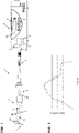
- the illustrated medical, in particular dental or dental-surgical, device 1 for determining the quality of a bone, in particular a jawbone comprises a handle element 9, a rotating threaded element 3 with at least one cutting edge, a motorized, in particular electromotive, drive 5 and a control device 2 with a measuring circuit 6.
- the handle element 9 designed as an angle piece comprises a head section 9A and a handle section 9B with a longitudinal axis 12.
- the rotating threaded element 3 is attached to the head section 9A, in particular in a detachable receptacle or holding device, in such a way that it is arranged at an angle to the longitudinal axis 12 of the handle section 9B is.
- At least one or more, in particular rotatable, drive shafts 13 and a gear unit 7, in particular with a reduction gear, are provided in the handle element 9 .
- the at least one drive shaft 13 and the gear unit 7 are in particular connected to one another and to the motor drive 5, so that a rotating movement of the motor drive 5 can be transmitted via the drive shaft 13 and the gear unit 7 to the rotating or rotatable threaded element 3.
- the (electric) motor drive 5 or electric motor is provided for driving the rotatable threaded element 3 , the at least one rotatable drive shaft 13 and the gear unit 7 .
- the motor drive 5 is preferably an independent component that can be detachably connected to the handle element 9 and/or the at least one rotatable drive shaft 13, for example via a coupling device.
- the motor drive 5 is designed as part of the handle element 9 .
- the (electro)motor drive 5 comprises in particular a stator, a rotor 5A that can be moved relative thereto and has at least one magnetic element, and at least one motor shaft that can be coupled or connected to the drive shaft 13 of the handle element 9 .
- the motor drive 5 and the handle element 9 are preferably connected to an operating and/or control console 11 via a supply hose 14 .
- the supply hose 14 there is at least one supply or control line or, in particular, several electrical conductors for transmitting drive energy for the motor drive 5 and for transmitting control, regulation or measurement signals, preferably also for transmitting energy for a lighting device.
- the supply hose 14 is, for example, detachably connected to the operating and/or control console 11 and detachably connected to the motor drive 5 or cannot be detachably connected for the user.
- a control device 2 is provided in the operating and/or control console 11 which comprises at least one measuring circuit 6 and preferably also an evaluation circuit 10 .
- at least one further circuit and/or at least one element of the device 1 is preferably provided in the console 11, for example: a control or regulating circuit of the motor drive 5; a comparator circuit, for example as part of the evaluation circuit 10, which is designed to compare the motor current values determined by the measuring circuit, the torque values which correlate or are essentially proportional to the motor current values or parameters derived therefrom with reference values for determining the quality of a bone; a display unit 4; at least one operating or adjusting element 8 for setting or selecting operating parameters; a circuit, in particular connected to the at least one operating or actuating element 8, for operating or setting operating parameters for the device 1 and/or for the electric motor drive 5; a memory unit in which measurement signals, motor current values, torque values correlating or essentially proportional to the motor current values, parameters derived therefrom, in particular
- the measuring circuit 6, preferably also the evaluation circuit 10 and at least one of the other circuits or elements mentioned above, is provided on the handle element 9 and/or on the motor drive 5, so that the device 1 for determining bone quality as a cordless handle element is formed.
- the control device 2, in particular the measuring circuit 6, is operatively connected, for example via electrical lines, to a first electrical contact device 2A and a second, preferably likewise electrical, contact device 2B.
- the first electrical contact device 2A connects the control device 2 or the measuring circuit 6 to the motor drive 5, in particular via the supply hose 14 and/or at least one supply or control line.
- the second electrical contact device 2B connects the control device 2 or the measuring circuit 6 to the display unit 4.
- the contact devices 2A, 2B are preferably part of the operating and/or control panel 11.
- the measuring circuit 6 is designed to determine, via the first electrical contact device 2A, values of the motor current with which the motor drive 5 is supplied for rotating the threaded element 3 that can be connected to the motor drive 5 . Since the motor current values are correlated or essentially proportional to the torque values transmitted by the motor drive 5 and since the motor current values or torque values are a measure of the quality of a bone, the measuring circuit 6 is thus designed to determine the bone quality, in particular during the driving of the rotating threaded element 3 or the advance of the rotating thread element 3 into the bone.
- the measuring circuit 6 is further designed to monitor and/or determine the depth of penetration (i.e. the progression of penetration) of the threaded element 3 into the bone.
- the measuring circuit 6 processes, for example, angle of rotation values of the rotor 5A of the motor drive 5 and/or the transmission ratio, in particular including the efficiency, of the transmission unit 7 of the handle element 9 and/or at least one property of the rotating threaded element 3, for example the pitch of the at least one Cutting edge, the shape of the cutting edge or the outer shape of the threaded element 3.
- the measuring circuit 6 is designed to generate measuring signals that relate the determined motor current values, the torque values that correlate or are essentially proportional to the motor current values, or parameters derived therefrom, with the penetration depth, and send these measuring signals via the second contact device 2B to the display unit 4 transfer.
- the display unit 4 is designed, on the basis of the measurement signals transmitted by the measuring circuit 6, to show the relationship between the motor current values determined, the torque values which correlate or are essentially proportional to the motor current values and/or the parameters derived therefrom, in particular the quality of a bone, and the penetration depth. in particular the qualitative depth profile of the bone.
- the display unit 4 includes, in particular, a screen integrated into the housing of the operating and/or control console 11, on which diagrams or graphic representations can be displayed.
- the display unit 4 is preferably also designed to display operating parameters of the device 1 and/or a parameter that can be changed by the operating or setting element 8 .
- At least a predetermined penetration depth of the rotating threaded element 3 into the bone is preferably stored in the control device 2, in particular in a memory element.
- the control device 2 is preferably designed to compare the monitored and/or determined penetration depth of the threaded element 3 with the at least one predetermined penetration depth and to stop the motor drive 5 and/or change its direction of rotation when the at least one predetermined penetration depth is reached or exceeded.
- the evaluation circuit 10 is designed as part of the control device 2 or the measuring circuit 6, the motor current values determined by the measuring circuit 6, the torque values correlating or essentially proportional to the motor current values or to compare parameters derived therefrom with comparative values for determining the quality of a bone and/or to combine them into bone quality classes and/or to assign them to bone quality classes.
- the evaluation circuit 10 is communicatively connected to the display unit 4 so that the values and/or the bone qualities and/or the bone quality classes compared by the evaluation circuit 10 can be displayed by or on the display unit 4 .
- control or regulating circuit of the motor drive or electric motor 5 is designed to control or regulate the motor drive 5 by means of electrical signals via the supply hose 14 or the at least one supply or control line. If necessary, the control or regulating circuit is also provided to operate the motorized drive 5 with a predetermined or fixed speed value.
- All circuits and circuits 6, 10 mentioned above are preferably designed as electronic circuits, in particular as part of a microprocessor.
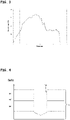
- FIG 2 a two-dimensional diagram that can be displayed by the display unit 4 is shown, which shows the relationship between the torque values determined, which are correlated or essentially proportional to the motor current values determined, and the penetration depth.
- the depth of penetration (preferably in mm) is plotted on the abscissa of the diagram and the torque values (preferably in Nm or Ncm) are plotted on the ordinate.
- the diagram is designed as a line diagram, with each individual value of the penetration depth being assigned a (specific) torque value.
- the user can thus read off the torque value determined by the measuring circuit 6 for any value of the penetration depth and/or use this to assess the quality of the bone, since, as already described above, the motor current values determined by the measuring circuit 6 or the correlating or essentially proportional torque values are a measure of bone quality (the higher the motor current values or the torque values, the higher or better the bone quality).
- FIG 3 shows a two-dimensional diagram that can be displayed by the display unit 4, which shows the relationship between the bone quality, which can be derived from the torque values determined by the measuring circuit 6 or the determined motor current values that are correlated or essentially proportional thereto, and the penetration depth.
- the depth of penetration (preferably in mm) is plotted on the abscissa of the diagram and the bone quality is plotted on the ordinate.
- the diagram is again designed as a line diagram, with each individual value of the penetration depth being assigned a bone quality class. This allows the user to read the bone quality or bone quality class for any value of the penetration depth.
- the diagram of figure 3 comprises, for example, four bone quality classes Q1-Q4, although of course more or fewer bone quality classes are also conceivable, for example two, three, five, six or more bone quality classes.
- Each bone quality class comprises or represents a predefined range of motor current values determined by the measurement circuit 6 or torque values determined correlating or substantially proportional thereto.
- bone quality class Q4 includes torque values from 8.00 Ncm - 6.00 Ncm
- bone quality class Q3 includes torque values from 5.99 Ncm - 4.00 Ncm, and so on figure 3
- the bone quality shown is high when the penetration depth is low and when the penetration depth is well advanced, i.e. the bone is hard, and in the area of the medium penetration depth the bone quality is low, i.e. the bone is soft.
- the figure 4 shows an exemplary embodiment of a particularly two-dimensional representation that can be displayed by the display unit 4, which shows the relationship between the bone quality, based on the motor current values determined by the measuring circuit 6, and the penetration depth on a schematically represented bone structure 15.
- a bore 16 is shown, also schematically, which in particular represents that bore into which the threaded element 3 of the medical, in particular dental or dental-surgical, device 1 cuts a thread.
- the penetration depth (in mm) is plotted.
- Horizontal bars or stripes extend from the ordinate and represent the quality of the bone in the form of bone quality classes.
- a bone quality class is also assigned to each individual value of the penetration depth in this representation.
- Each bone quality class comprises or represents a predefined range of motor current values or torque values correlated or substantially proportional thereto determined by the measuring circuit 6, as explained in connection with the diagram of FIG figure 3 is described.
- the horizontal bars or strips particularly preferably have different markings or colors, in particular each bone quality class is assigned its own marking or color.
- the representation of figure 4 includes, for example, three bone quality classes Q1-Q3, although of course more or fewer bone quality classes are conceivable, for example two, four, five, six or more bone quality classes.
- the representation according to figure 4 provides the user with a particularly quick and easy-to-understand overview of the development of the bone quality along the depth of penetration.
- the invention is not limited to the exemplary embodiments described, but includes all versions that apply or contain the basic, analogous functional principle of the invention according to the claims. Furthermore, all features of all described and illustrated exemplary embodiments can be combined with one another.
Landscapes
- Health & Medical Sciences (AREA)
- Life Sciences & Earth Sciences (AREA)
- Oral & Maxillofacial Surgery (AREA)
- Public Health (AREA)
- Dentistry (AREA)
- Veterinary Medicine (AREA)
- Animal Behavior & Ethology (AREA)
- General Health & Medical Sciences (AREA)
- Engineering & Computer Science (AREA)
- Surgery (AREA)
- Orthopedic Medicine & Surgery (AREA)
- Epidemiology (AREA)
- Biomedical Technology (AREA)
- Medical Informatics (AREA)
- Molecular Biology (AREA)
- Heart & Thoracic Surgery (AREA)
- Biophysics (AREA)
- Rheumatology (AREA)
- Physics & Mathematics (AREA)
- Pathology (AREA)
- Nuclear Medicine, Radiotherapy & Molecular Imaging (AREA)
- Physical Education & Sports Medicine (AREA)
- Water Supply & Treatment (AREA)
- Dental Tools And Instruments Or Auxiliary Dental Instruments (AREA)
- Dental Prosthetics (AREA)
- Instructional Devices (AREA)
Claims (12)
- Dispositif médical (1), en particulier dentaire pour la détermination de la qualité d'un os par taillage d'un filetage dans l'os au moyen d'un élément fileté rotatif (3) avec au moins un tranchant, dans lequel le dispositif médical (1), en particulier dentaire comprend un dispositif de commande (2) qui présente un premier dispositif de contact électrique (2A) pour le raccordement à un entraînement motorisé (5), un deuxième dispositif de contact (2B) pour le raccordement à une unité d'affichage (4) et un circuit de mesure (6), lequel est raccordé de manière opérative au premier dispositif de contact électrique (2A) et au deuxième dispositif de contact (2B), dans lequel le circuit de mesure (6) est réalisé pour:(i) via le premier dispositif de contact électrique (2A), déterminer des valeurs du courant de moteur avec lequel l'entraînement motorisé (5) est alimenté pour l'entraînement rotatif de l'élément fileté (3) pouvant être raccordé à l'entraînement motorisé (5), dans lequel les valeurs du courant de moteur sont en corrélation avec, ou sensiblement proportionnelles à des valeurs de couple à transmettre de l'entraînement motorisé (5) et dans lequel les valeurs de courant de moteur ou valeurs de couple sont une mesure pour la qualité d'un os,(ii) surveiller et/ou déterminer la profondeur de pénétration de l'élément fileté (3) dans l'os et(iii) générer des signaux de mesure, lesquels mettent en rapport les valeurs de courant de moteur déterminées, les valeurs de couple en corrélation avec les valeurs de courant de moteur ou sensiblement proportionnelles à celles-ci ou la qualité d'un os dérivée des valeurs de courant de moteur déterminées ou des valeurs de couple, avec la profondeur de pénétration, et transmettre ces signaux de mesure via le deuxième dispositif de contact (2B) à l'unité d'affichage (4) de sorte que l'unité d'affichage (4) reproduit, sur la base des signaux de mesure transmis, le rapport entre la profondeur de pénétration et au moins l'un des paramètres suivants, à savoir les valeurs de courant de moteur déterminées, les valeurs de couple en corrélation avec les valeurs de courant de moteur ou sensiblement proportionnelles à celles-ci ou la qualité d'un os, caractérisé en ce quele dispositif de commande (2) présente un circuit d'évaluation (10), lequel est réalisé pour regrouper les valeurs de courant de moteur déterminées par le circuit de mesure (6) ou les valeurs de couple en corrélation avec les valeurs de courant de moteur ou sensiblement proportionnelles à celles-ci dans des classes de qualité osseuse ou les associer à des classes de qualité osseuse,et caractérisé par une unité d'affichage (4) raccordée de manière communicative au deuxième dispositif de contact (2B), laquelle reproduit le rapport entre la profondeur de pénétration et la qualité d'un os,et caractérisé en ce que- l'unité d'affichage (4) représente graphiquement le rapport entre la profondeur de pénétration et la qualité d'un os, et- l'unité d'affichage (4) est réalisée, sur la base des signaux de mesure du circuit de mesure (6), pour afficher un diagramme ou une représentation schématique d'une structure osseuse avec lequel/laquelle on associe à chaque valeur de la profondeur de pénétration des qualités d'un os regroupées en classes de qualité osseuse.
- Dispositif médical (1), en particulier dentaire selon la revendication 1, caractérisé en ce que
le circuit de mesure (6) est réalisé, pour la surveillance et/ou détermination de la profondeur de pénétration de l'élément fileté (3) dans l'os, pour traiter des valeurs d'angle de rotation d'un rotor (5A) de l'entraînement motorisé (5). - Dispositif médical (1), en particulier dentaire selon la revendication 1 ou 2, caractérisé en ce que
le circuit de mesure (6) est réalisé, pour la surveillance et/ou détermination de la profondeur de pénétration de l'élément fileté (3) dans l'os, pour tenir compte du rapport de transmission, en particulier y compris de l'efficacité, d'une unité de transmission (7) disposée entre l'entraînement motorisé (5) et l'élément fileté (3) du dispositif médical (1), en particulier dentaire. - Dispositif médical (1), en particulier dentaire selon l'une des revendications précédentes, caractérisé en ce que
le circuit de mesure (6) est réalisé, pour la surveillance et/ou détermination de la profondeur de pénétration de l'élément fileté (3) dans l'os, pour tenir compte d'au moins une propriété de l'élément fileté (3), par exemple le pas de l'au moins un tranchant, la forme du tranchant ou la forme extérieure de l'élément fileté (3). - Dispositif médical (1), en particulier dentaire selon l'une des revendications précédentes, caractérisé en ce que
au moins une profondeur de pénétration prédéfinie est enregistrée dans le dispositif de commande (2). - Dispositif médical (1), en particulier dentaire selon l'une des revendications précédentes, caractérisé en ce que
plusieurs profondeurs de pénétration prédéterminées sont enregistrées dans le dispositif de commande (2), lesquelles peuvent être sélectionnées par l'utilisateur via un élément de réglage (8). - Dispositif médical (1), en particulier dentaire selon la revendication 5 ou 6, caractérisé en ce que
le dispositif de commande (2) est réalisé pour comparer la profondeur de pénétration surveillée et/ou déterminée de l'élément fileté (3) avec l'au moins une profondeur de pénétration prédéfinie et, en cas d'atteinte ou dépassement de l'au moins une profondeur de pénétration prédéfinie, arrêter l'entraînement motorisé (5) et/ou modifier son sens de rotation. - Dispositif médical (1), en particulier dentaire selon l'une des revendications précédentes, caractérisé en ce que
le dispositif de commande (2) est réalisé pour commencer avec la surveillance et/ou la détermination ou avec un enregistrement de la profondeur de pénétration de l'élément fileté (3) dans l'os seulement après avoir atteint ou dépassé une valeur de seuil de courant de moteur ou valeur de seuil de couple prédéfinie. - Dispositif médical (1), en particulier dentaire selon l'une des revendications précédentes, caractérisé en ce que
le dispositif (1) présente en outre un entraînement motorisé (5) et un élément de poignée (9) pouvant être relié, ou relié, à l'élément fileté (3), lequel peut être couplé avec l'entraînement motorisé (5) ou comprend l'entraînement motorisé (5). - Dispositif médical (1), en particulier dentaire selon l'une des revendications 1 - 9,
caractérisé en ce que
le circuit d'évaluation (10) est relié à l'unité d'affichage (4) de sorte que l'unité d'affichage (4) représente les classes de qualité osseuse. - Dispositif médical (1), en particulier dentaire selon l'une des revendications précédentes, caractérisé en ce que
le dispositif de commande (2) est en outre réalisé pour déterminer l'énergie, le travail ou la puissance nécessaire ou utilisé(e) par l'entraînement motorisé (5) pendant le taillage du filetage dans un os et transmettre un signal d'affichage correspondant via le deuxième dispositif de contact (2B) à l'unité d'affichage (4) de sorte que, sur la base du signal d'affichage transmis, l'unité d'affichage (4) reproduit l'énergie, le travail ou la puissance nécessaire ou utilisé(e) pendant le taillage du filetage. - Dispositif médical (1), en particulier dentaire selon l'une des revendications précédentes, caractérisé en ce que
l'élément fileté rotatif (3) comprend un taraud ou un implant.
Priority Applications (3)
| Application Number | Priority Date | Filing Date | Title |
|---|---|---|---|
| ES18157376T ES2758093T5 (es) | 2015-07-20 | 2015-07-20 | Dispositivo médico, particularmente dental, para determinar la calidad de un hueso |
| FIEP18157376.7T FI3345569T4 (fi) | 2015-07-20 | 2015-07-20 | Lääkinnällinen, erityisesti dentaalinen laite luun laadun määrittämiseksi |
| EP18157376.7A EP3345569B2 (fr) | 2015-07-20 | 2015-07-20 | Dispositif médical, notamment dentaire, destiné à l'évaluation de la qualité d'un os |
Applications Claiming Priority (2)
| Application Number | Priority Date | Filing Date | Title |
|---|---|---|---|
| EP18157376.7A EP3345569B2 (fr) | 2015-07-20 | 2015-07-20 | Dispositif médical, notamment dentaire, destiné à l'évaluation de la qualité d'un os |
| EP15177428.8A EP3120802B1 (fr) | 2015-07-20 | 2015-07-20 | Dispositif médical, notamment dentaire, destiné à l'évaluation de la qualité d'un os |
Related Parent Applications (2)
| Application Number | Title | Priority Date | Filing Date |
|---|---|---|---|
| EP15177428.8A Division EP3120802B1 (fr) | 2015-07-20 | 2015-07-20 | Dispositif médical, notamment dentaire, destiné à l'évaluation de la qualité d'un os |
| EP15177428.8A Division-Into EP3120802B1 (fr) | 2015-07-20 | 2015-07-20 | Dispositif médical, notamment dentaire, destiné à l'évaluation de la qualité d'un os |
Publications (3)
| Publication Number | Publication Date |
|---|---|
| EP3345569A1 EP3345569A1 (fr) | 2018-07-11 |
| EP3345569B1 EP3345569B1 (fr) | 2019-09-04 |
| EP3345569B2 true EP3345569B2 (fr) | 2022-11-23 |
Family
ID=53724019
Family Applications (2)
| Application Number | Title | Priority Date | Filing Date |
|---|---|---|---|
| EP18157376.7A Active EP3345569B2 (fr) | 2015-07-20 | 2015-07-20 | Dispositif médical, notamment dentaire, destiné à l'évaluation de la qualité d'un os |
| EP15177428.8A Active EP3120802B1 (fr) | 2015-07-20 | 2015-07-20 | Dispositif médical, notamment dentaire, destiné à l'évaluation de la qualité d'un os |
Family Applications After (1)
| Application Number | Title | Priority Date | Filing Date |
|---|---|---|---|
| EP15177428.8A Active EP3120802B1 (fr) | 2015-07-20 | 2015-07-20 | Dispositif médical, notamment dentaire, destiné à l'évaluation de la qualité d'un os |
Country Status (10)
| Country | Link |
|---|---|
| US (2) | US10973457B2 (fr) |
| EP (2) | EP3345569B2 (fr) |
| JP (1) | JP6738404B2 (fr) |
| KR (1) | KR101986467B1 (fr) |
| CN (2) | CN113349979B (fr) |
| AU (1) | AU2016296196B2 (fr) |
| CA (2) | CA2989513C (fr) |
| ES (2) | ES2758093T5 (fr) |
| FI (1) | FI3345569T4 (fr) |
| WO (1) | WO2017012998A1 (fr) |
Families Citing this family (6)
| Publication number | Priority date | Publication date | Assignee | Title |
|---|---|---|---|---|
| KR102417755B1 (ko) * | 2019-02-01 | 2022-07-05 | 비엔-에어 홀딩 에스에이 | 골질을 측정하기 위한 방법 및 도구 |
| KR102918787B1 (ko) * | 2023-04-20 | 2026-01-27 | 오스템임플란트 주식회사 | 임플란트 시술용 드릴을 이용한 골질 판정 시스템 및 방법 |
| WO2025214924A1 (fr) | 2024-04-08 | 2025-10-16 | W&H Dentalwerk Bürmoos GmbH | Unité d'entraînement et d'alimentation pour implanter des implants dentaires |
| EP4631468A1 (fr) | 2024-04-08 | 2025-10-15 | W & H Dentalwerk Bürmoos GmbH | Dispositif de traitement médical, en particulier dentaire, comprenant un réservoir de liquide et un tel réservoir de liquide |
| EP4631469A1 (fr) | 2024-04-08 | 2025-10-15 | W & H Dentalwerk Bürmoos GmbH | Unité d'entraînement et d'alimentation pour l'implantation d'implants dentaires |
| KR20260032794A (ko) * | 2024-08-30 | 2026-03-10 | 주식회사 덴큐임플란트 | 임플란트 서지컬 키트의 드릴링 온도를 이용한 인공지능 기반 골질 판별 시스템 |
Family Cites Families (12)
| Publication number | Priority date | Publication date | Assignee | Title |
|---|---|---|---|---|
| CA2158854C (fr) * | 1994-01-25 | 2007-04-10 | Andrew Joseph Stanley Dawood | Appareil d'essai de l'ajustement passif de structures retenues par vis |
| SE512778C2 (sv) * | 1998-09-17 | 2000-05-15 | Nobel Biocare Ab | Anordning vid instrument som innefattar eller är anslutet till ett idragningsverktyg |
| AU2006244518A1 (en) * | 2005-05-05 | 2006-11-16 | The Regents Of The University Of California | Methods and instruments for assessing bone fracture risk |
| ITMI20060652A1 (it) | 2006-04-04 | 2007-10-05 | I D I Evolution S R L | Sistema di controllo di un motore elettrico per applicazioni chirurgiche |
| ITMI20060653A1 (it) | 2006-04-04 | 2007-10-05 | I D I Evolution S R L | Sistema di identificazione della tipologia ossea |
| WO2008052367A1 (fr) * | 2006-10-31 | 2008-05-08 | Ao Technology Ag | Procédé et dispositif servant à mesurer la résistance mécanique locale d'un corps poreux |
| EP2358295A2 (fr) * | 2008-11-18 | 2011-08-24 | Ibur, Llc | Dispositif et procédé dentaire pour lier des données physiques et numériques à des fins de diagnostic, de planification de traitements, de formation des patients, de communication, de fabrication et de transfert de données |
| US8894654B2 (en) * | 2010-03-31 | 2014-11-25 | Smart Medical Devices, Inc. | Depth controllable and measurable medical driver devices and methods of use |
| ITBA20110054A1 (it) * | 2011-10-03 | 2013-04-04 | Angelo Tarullo | "equipaggiamento per la composizione di fratture ossee in chirurgia ortopedica" |
| MY161893A (en) * | 2011-11-25 | 2017-05-12 | Braebon Medical Corp | Method and apparatus for verifying compliance with dental appliance therapy |
| EP3251617A1 (fr) * | 2012-11-19 | 2017-12-06 | Sandvik Intellectual Property AB | Foret et taraud et procédé d'évaluation préopératoire de la qualité d'un os |
| EP2832285A1 (fr) * | 2013-07-31 | 2015-02-04 | ETH Zurich | Instrument de traitement chirurgical et procédé pour déterminer la résistance mécanique locale d'un os |
-
2015
- 2015-07-20 ES ES18157376T patent/ES2758093T5/es active Active
- 2015-07-20 FI FIEP18157376.7T patent/FI3345569T4/fi active
- 2015-07-20 EP EP18157376.7A patent/EP3345569B2/fr active Active
- 2015-07-20 EP EP15177428.8A patent/EP3120802B1/fr active Active
- 2015-07-20 ES ES15177428.8T patent/ES2684635T3/es active Active
-
2016
- 2016-07-15 KR KR1020187001541A patent/KR101986467B1/ko active Active
- 2016-07-15 WO PCT/EP2016/066846 patent/WO2017012998A1/fr not_active Ceased
- 2016-07-15 CA CA2989513A patent/CA2989513C/fr active Active
- 2016-07-15 AU AU2016296196A patent/AU2016296196B2/en active Active
- 2016-07-15 CA CA3119689A patent/CA3119689C/fr active Active
- 2016-07-15 CN CN202110769940.7A patent/CN113349979B/zh active Active
- 2016-07-15 JP JP2018502752A patent/JP6738404B2/ja active Active
- 2016-07-15 CN CN201680053035.9A patent/CN108135675B/zh active Active
-
2018
- 2018-01-17 US US15/873,853 patent/US10973457B2/en active Active
-
2021
- 2021-03-10 US US17/198,182 patent/US11617535B2/en active Active
Non-Patent Citations (1)
| Title |
|---|
| D A DI STEFANO, ET AL: "A possible novel objective intraoperative measurement of maxillary bone density", MINERVA STOMATOLOGICA, vol. 62, no. 7-8, 1 July 2013 (2013-07-01), pages 259 - 266 † |
Also Published As
| Publication number | Publication date |
|---|---|
| CA2989513A1 (fr) | 2017-01-26 |
| US10973457B2 (en) | 2021-04-13 |
| KR101986467B1 (ko) | 2019-06-05 |
| ES2758093T3 (es) | 2020-05-04 |
| CA2989513C (fr) | 2021-09-21 |
| US20210186413A1 (en) | 2021-06-24 |
| JP2018523514A (ja) | 2018-08-23 |
| EP3345569A1 (fr) | 2018-07-11 |
| ES2758093T5 (es) | 2023-04-17 |
| CA3119689A1 (fr) | 2017-01-26 |
| CN108135675B (zh) | 2021-05-28 |
| FI3345569T4 (fi) | 2023-03-15 |
| EP3120802A1 (fr) | 2017-01-25 |
| US20180153466A1 (en) | 2018-06-07 |
| WO2017012998A1 (fr) | 2017-01-26 |
| CN113349979A (zh) | 2021-09-07 |
| AU2016296196B2 (en) | 2018-12-06 |
| CA3119689C (fr) | 2023-01-31 |
| US11617535B2 (en) | 2023-04-04 |
| CN108135675A (zh) | 2018-06-08 |
| ES2684635T3 (es) | 2018-10-03 |
| JP6738404B2 (ja) | 2020-08-12 |
| EP3120802B1 (fr) | 2018-05-23 |
| CN113349979B (zh) | 2022-06-14 |
| AU2016296196A1 (en) | 2018-03-15 |
| EP3345569B1 (fr) | 2019-09-04 |
| KR20180019673A (ko) | 2018-02-26 |
Similar Documents
| Publication | Publication Date | Title |
|---|---|---|
| EP3345569B1 (fr) | Dispositif médical, notamment dentaire, destiné à l'évaluation de la qualité d'un os | |
| EP1399707B1 (fr) | Procede et dispositif de determination du contour d'une cavite pratiquee dans une piece | |
| DE102013002509B4 (de) | Zahnmedizinische Behandlungsvorrichtung | |
| DE102013002510B4 (de) | Zahnmedizinische Behandlungsvorrichtung | |
| EP3113911B1 (fr) | Affichage de puissance adaptatif | |
| DE102008012677A1 (de) | Vorrichtung zur Messung der Länge eines Wurzelkanals; Vorrichtung zur Behandlung des Wurzelkanals | |
| EP2540249A1 (fr) | Procédé de commande d'un dispositif d'entraînement pour la préparation d'un canal radiculaire et pièce à main rotative destinée à la préparation de canaux radiculaires | |
| DE102021121777B4 (de) | Verfahren zum Betreiben eines Trockenbauschraubers, Computerprogramm und Trockenbauschrauber | |
| DE10219166B4 (de) | Medizinische Behandlungsvorrichtung | |
| EP3375405A1 (fr) | Dispositif destiné au fonctionnement d'un scanner intra-buccal | |
| DE20207967U1 (de) | Bohr-, Fräs- und/oder Schraubmaschine, insbesondere für medizinische Anwendungen | |
| EP3599443A1 (fr) | Procédé de détection optique de la géométrie de surface de la gencive | |
| DE202014103576U1 (de) | Kabelloses Fußbediengerät | |
| EP2266485A1 (fr) | Elément de guidage de l'air essentiellement pour l'application adjacente à l'enveloppe extérieure dans la zone du passage entre deux véhicules reliés ensembles de manière articulée |
Legal Events
| Date | Code | Title | Description |
|---|---|---|---|
| PUAI | Public reference made under article 153(3) epc to a published international application that has entered the european phase |
Free format text: ORIGINAL CODE: 0009012 |
|
| STAA | Information on the status of an ep patent application or granted ep patent |
Free format text: STATUS: THE APPLICATION HAS BEEN PUBLISHED |
|
| AC | Divisional application: reference to earlier application |
Ref document number: 3120802 Country of ref document: EP Kind code of ref document: P |
|
| AK | Designated contracting states |
Kind code of ref document: A1 Designated state(s): AL AT BE BG CH CY CZ DE DK EE ES FI FR GB GR HR HU IE IS IT LI LT LU LV MC MK MT NL NO PL PT RO RS SE SI SK SM TR |
|
| STAA | Information on the status of an ep patent application or granted ep patent |
Free format text: STATUS: REQUEST FOR EXAMINATION WAS MADE |
|
| 17P | Request for examination filed |
Effective date: 20181210 |
|
| RBV | Designated contracting states (corrected) |
Designated state(s): AL AT BE BG CH CY CZ DE DK EE ES FI FR GB GR HR HU IE IS IT LI LT LU LV MC MK MT NL NO PL PT RO RS SE SI SK SM TR |
|
| GRAP | Despatch of communication of intention to grant a patent |
Free format text: ORIGINAL CODE: EPIDOSNIGR1 |
|
| STAA | Information on the status of an ep patent application or granted ep patent |
Free format text: STATUS: GRANT OF PATENT IS INTENDED |
|
| INTG | Intention to grant announced |
Effective date: 20190409 |
|
| RIN1 | Information on inventor provided before grant (corrected) |
Inventor name: PLOY, GERNOT Inventor name: BRUGGER, WILHELM |
|
| GRAS | Grant fee paid |
Free format text: ORIGINAL CODE: EPIDOSNIGR3 |
|
| GRAA | (expected) grant |
Free format text: ORIGINAL CODE: 0009210 |
|
| STAA | Information on the status of an ep patent application or granted ep patent |
Free format text: STATUS: THE PATENT HAS BEEN GRANTED |
|
| AC | Divisional application: reference to earlier application |
Ref document number: 3120802 Country of ref document: EP Kind code of ref document: P |
|
| AK | Designated contracting states |
Kind code of ref document: B1 Designated state(s): AL AT BE BG CH CY CZ DE DK EE ES FI FR GB GR HR HU IE IS IT LI LT LU LV MC MK MT NL NO PL PT RO RS SE SI SK SM TR |
|
| REG | Reference to a national code |
Ref country code: GB Ref legal event code: FG4D Free format text: NOT ENGLISH |
|
| REG | Reference to a national code |
Ref country code: CH Ref legal event code: EP |
|
| REG | Reference to a national code |
Ref country code: AT Ref legal event code: REF Ref document number: 1174283 Country of ref document: AT Kind code of ref document: T Effective date: 20190915 |
|
| REG | Reference to a national code |
Ref country code: DE Ref legal event code: R096 Ref document number: 502015010281 Country of ref document: DE |
|
| REG | Reference to a national code |
Ref country code: IE Ref legal event code: FG4D Free format text: LANGUAGE OF EP DOCUMENT: GERMAN |
|
| REG | Reference to a national code |
Ref country code: SE Ref legal event code: TRGR |
|
| REG | Reference to a national code |
Ref country code: NL Ref legal event code: MP Effective date: 20190904 |
|
| REG | Reference to a national code |
Ref country code: LT Ref legal event code: MG4D |
|
| PG25 | Lapsed in a contracting state [announced via postgrant information from national office to epo] |
Ref country code: HR Free format text: LAPSE BECAUSE OF FAILURE TO SUBMIT A TRANSLATION OF THE DESCRIPTION OR TO PAY THE FEE WITHIN THE PRESCRIBED TIME-LIMIT Effective date: 20190904 Ref country code: LT Free format text: LAPSE BECAUSE OF FAILURE TO SUBMIT A TRANSLATION OF THE DESCRIPTION OR TO PAY THE FEE WITHIN THE PRESCRIBED TIME-LIMIT Effective date: 20190904 Ref country code: BG Free format text: LAPSE BECAUSE OF FAILURE TO SUBMIT A TRANSLATION OF THE DESCRIPTION OR TO PAY THE FEE WITHIN THE PRESCRIBED TIME-LIMIT Effective date: 20191204 Ref country code: NO Free format text: LAPSE BECAUSE OF FAILURE TO SUBMIT A TRANSLATION OF THE DESCRIPTION OR TO PAY THE FEE WITHIN THE PRESCRIBED TIME-LIMIT Effective date: 20191204 |
|
| PG25 | Lapsed in a contracting state [announced via postgrant information from national office to epo] |
Ref country code: RS Free format text: LAPSE BECAUSE OF FAILURE TO SUBMIT A TRANSLATION OF THE DESCRIPTION OR TO PAY THE FEE WITHIN THE PRESCRIBED TIME-LIMIT Effective date: 20190904 Ref country code: GR Free format text: LAPSE BECAUSE OF FAILURE TO SUBMIT A TRANSLATION OF THE DESCRIPTION OR TO PAY THE FEE WITHIN THE PRESCRIBED TIME-LIMIT Effective date: 20191205 Ref country code: LV Free format text: LAPSE BECAUSE OF FAILURE TO SUBMIT A TRANSLATION OF THE DESCRIPTION OR TO PAY THE FEE WITHIN THE PRESCRIBED TIME-LIMIT Effective date: 20190904 Ref country code: AL Free format text: LAPSE BECAUSE OF FAILURE TO SUBMIT A TRANSLATION OF THE DESCRIPTION OR TO PAY THE FEE WITHIN THE PRESCRIBED TIME-LIMIT Effective date: 20190904 |
|
| PG25 | Lapsed in a contracting state [announced via postgrant information from national office to epo] |
Ref country code: NL Free format text: LAPSE BECAUSE OF FAILURE TO SUBMIT A TRANSLATION OF THE DESCRIPTION OR TO PAY THE FEE WITHIN THE PRESCRIBED TIME-LIMIT Effective date: 20190904 Ref country code: EE Free format text: LAPSE BECAUSE OF FAILURE TO SUBMIT A TRANSLATION OF THE DESCRIPTION OR TO PAY THE FEE WITHIN THE PRESCRIBED TIME-LIMIT Effective date: 20190904 Ref country code: RO Free format text: LAPSE BECAUSE OF FAILURE TO SUBMIT A TRANSLATION OF THE DESCRIPTION OR TO PAY THE FEE WITHIN THE PRESCRIBED TIME-LIMIT Effective date: 20190904 Ref country code: PT Free format text: LAPSE BECAUSE OF FAILURE TO SUBMIT A TRANSLATION OF THE DESCRIPTION OR TO PAY THE FEE WITHIN THE PRESCRIBED TIME-LIMIT Effective date: 20200106 Ref country code: PL Free format text: LAPSE BECAUSE OF FAILURE TO SUBMIT A TRANSLATION OF THE DESCRIPTION OR TO PAY THE FEE WITHIN THE PRESCRIBED TIME-LIMIT Effective date: 20190904 |
|
| REG | Reference to a national code |
Ref country code: ES Ref legal event code: FG2A Ref document number: 2758093 Country of ref document: ES Kind code of ref document: T3 Effective date: 20200504 |
|
| PG25 | Lapsed in a contracting state [announced via postgrant information from national office to epo] |
Ref country code: SM Free format text: LAPSE BECAUSE OF FAILURE TO SUBMIT A TRANSLATION OF THE DESCRIPTION OR TO PAY THE FEE WITHIN THE PRESCRIBED TIME-LIMIT Effective date: 20190904 Ref country code: IS Free format text: LAPSE BECAUSE OF FAILURE TO SUBMIT A TRANSLATION OF THE DESCRIPTION OR TO PAY THE FEE WITHIN THE PRESCRIBED TIME-LIMIT Effective date: 20200224 Ref country code: SK Free format text: LAPSE BECAUSE OF FAILURE TO SUBMIT A TRANSLATION OF THE DESCRIPTION OR TO PAY THE FEE WITHIN THE PRESCRIBED TIME-LIMIT Effective date: 20190904 Ref country code: CZ Free format text: LAPSE BECAUSE OF FAILURE TO SUBMIT A TRANSLATION OF THE DESCRIPTION OR TO PAY THE FEE WITHIN THE PRESCRIBED TIME-LIMIT Effective date: 20190904 |
|
| REG | Reference to a national code |
Ref country code: DE Ref legal event code: R026 Ref document number: 502015010281 Country of ref document: DE |
|
| PLBI | Opposition filed |
Free format text: ORIGINAL CODE: 0009260 |
|
| PLAX | Notice of opposition and request to file observation + time limit sent |
Free format text: ORIGINAL CODE: EPIDOSNOBS2 |
|
| REG | Reference to a national code |
Ref country code: FI Ref legal event code: MDE Opponent name: I.D.I. EVOLUTION S.R.L. |
|
| 26 | Opposition filed |
Opponent name: I.D.I. EVOLUTION S.R.L. Effective date: 20200603 |
|
| PG2D | Information on lapse in contracting state deleted |
Ref country code: IS |
|
| PG25 | Lapsed in a contracting state [announced via postgrant information from national office to epo] |
Ref country code: DK Free format text: LAPSE BECAUSE OF FAILURE TO SUBMIT A TRANSLATION OF THE DESCRIPTION OR TO PAY THE FEE WITHIN THE PRESCRIBED TIME-LIMIT Effective date: 20190904 Ref country code: IS Free format text: LAPSE BECAUSE OF FAILURE TO SUBMIT A TRANSLATION OF THE DESCRIPTION OR TO PAY THE FEE WITHIN THE PRESCRIBED TIME-LIMIT Effective date: 20200105 |
|
| PG25 | Lapsed in a contracting state [announced via postgrant information from national office to epo] |
Ref country code: SI Free format text: LAPSE BECAUSE OF FAILURE TO SUBMIT A TRANSLATION OF THE DESCRIPTION OR TO PAY THE FEE WITHIN THE PRESCRIBED TIME-LIMIT Effective date: 20190904 |
|
| PLBB | Reply of patent proprietor to notice(s) of opposition received |
Free format text: ORIGINAL CODE: EPIDOSNOBS3 |
|
| PG25 | Lapsed in a contracting state [announced via postgrant information from national office to epo] |
Ref country code: MC Free format text: LAPSE BECAUSE OF FAILURE TO SUBMIT A TRANSLATION OF THE DESCRIPTION OR TO PAY THE FEE WITHIN THE PRESCRIBED TIME-LIMIT Effective date: 20190904 |
|
| GBPC | Gb: european patent ceased through non-payment of renewal fee |
Effective date: 20200720 |
|
| REG | Reference to a national code |
Ref country code: BE Ref legal event code: MM Effective date: 20200731 |
|
| PG25 | Lapsed in a contracting state [announced via postgrant information from national office to epo] |
Ref country code: GB Free format text: LAPSE BECAUSE OF NON-PAYMENT OF DUE FEES Effective date: 20200720 Ref country code: LU Free format text: LAPSE BECAUSE OF NON-PAYMENT OF DUE FEES Effective date: 20200720 |
|
| PG25 | Lapsed in a contracting state [announced via postgrant information from national office to epo] |
Ref country code: BE Free format text: LAPSE BECAUSE OF NON-PAYMENT OF DUE FEES Effective date: 20200731 |
|
| PG25 | Lapsed in a contracting state [announced via postgrant information from national office to epo] |
Ref country code: IE Free format text: LAPSE BECAUSE OF NON-PAYMENT OF DUE FEES Effective date: 20200720 |
|
| REG | Reference to a national code |
Ref country code: AT Ref legal event code: MM01 Ref document number: 1174283 Country of ref document: AT Kind code of ref document: T Effective date: 20200720 |
|
| PG25 | Lapsed in a contracting state [announced via postgrant information from national office to epo] |
Ref country code: AT Free format text: LAPSE BECAUSE OF NON-PAYMENT OF DUE FEES Effective date: 20200720 |
|
| APBM | Appeal reference recorded |
Free format text: ORIGINAL CODE: EPIDOSNREFNO |
|
| APBP | Date of receipt of notice of appeal recorded |
Free format text: ORIGINAL CODE: EPIDOSNNOA2O |
|
| APAH | Appeal reference modified |
Free format text: ORIGINAL CODE: EPIDOSCREFNO |
|
| APBM | Appeal reference recorded |
Free format text: ORIGINAL CODE: EPIDOSNREFNO |
|
| APBP | Date of receipt of notice of appeal recorded |
Free format text: ORIGINAL CODE: EPIDOSNNOA2O |
|
| PG25 | Lapsed in a contracting state [announced via postgrant information from national office to epo] |
Ref country code: TR Free format text: LAPSE BECAUSE OF FAILURE TO SUBMIT A TRANSLATION OF THE DESCRIPTION OR TO PAY THE FEE WITHIN THE PRESCRIBED TIME-LIMIT Effective date: 20190904 Ref country code: MT Free format text: LAPSE BECAUSE OF FAILURE TO SUBMIT A TRANSLATION OF THE DESCRIPTION OR TO PAY THE FEE WITHIN THE PRESCRIBED TIME-LIMIT Effective date: 20190904 Ref country code: CY Free format text: LAPSE BECAUSE OF FAILURE TO SUBMIT A TRANSLATION OF THE DESCRIPTION OR TO PAY THE FEE WITHIN THE PRESCRIBED TIME-LIMIT Effective date: 20190904 |
|
| PG25 | Lapsed in a contracting state [announced via postgrant information from national office to epo] |
Ref country code: MK Free format text: LAPSE BECAUSE OF FAILURE TO SUBMIT A TRANSLATION OF THE DESCRIPTION OR TO PAY THE FEE WITHIN THE PRESCRIBED TIME-LIMIT Effective date: 20190904 |
|
| APBU | Appeal procedure closed |
Free format text: ORIGINAL CODE: EPIDOSNNOA9O |
|
| PUAH | Patent maintained in amended form |
Free format text: ORIGINAL CODE: 0009272 |
|
| STAA | Information on the status of an ep patent application or granted ep patent |
Free format text: STATUS: PATENT MAINTAINED AS AMENDED |
|
| 27A | Patent maintained in amended form |
Effective date: 20221123 |
|
| AK | Designated contracting states |
Kind code of ref document: B2 Designated state(s): AL AT BE BG CH CY CZ DE DK EE ES FI FR GB GR HR HU IE IS IT LI LT LU LV MC MK MT NL NO PL PT RO RS SE SI SK SM TR |
|
| REG | Reference to a national code |
Ref country code: DE Ref legal event code: R102 Ref document number: 502015010281 Country of ref document: DE |
|
| REG | Reference to a national code |
Ref country code: SE Ref legal event code: RPEO |
|
| REG | Reference to a national code |
Ref country code: ES Ref legal event code: DC2A Ref document number: 2758093 Country of ref document: ES Kind code of ref document: T5 Effective date: 20230417 |
|
| P01 | Opt-out of the competence of the unified patent court (upc) registered |
Effective date: 20230531 |
|
| PGFP | Annual fee paid to national office [announced via postgrant information from national office to epo] |
Ref country code: FI Payment date: 20250725 Year of fee payment: 11 Ref country code: ES Payment date: 20250826 Year of fee payment: 11 |
|
| PGFP | Annual fee paid to national office [announced via postgrant information from national office to epo] |
Ref country code: DE Payment date: 20250722 Year of fee payment: 11 |
|
| PGFP | Annual fee paid to national office [announced via postgrant information from national office to epo] |
Ref country code: IT Payment date: 20250724 Year of fee payment: 11 |
|
| PGFP | Annual fee paid to national office [announced via postgrant information from national office to epo] |
Ref country code: FR Payment date: 20250725 Year of fee payment: 11 |
|
| PGFP | Annual fee paid to national office [announced via postgrant information from national office to epo] |
Ref country code: CH Payment date: 20250801 Year of fee payment: 11 Ref country code: SE Payment date: 20250722 Year of fee payment: 11 |
|
| REG | Reference to a national code |
Ref country code: CH Ref legal event code: U11 Free format text: ST27 STATUS EVENT CODE: U-0-0-U10-U11 (AS PROVIDED BY THE NATIONAL OFFICE) Effective date: 20260801 |