EP3352111A1 - Procédé de détection d'événements critiques - Google Patents
Procédé de détection d'événements critiques Download PDFInfo
- Publication number
- EP3352111A1 EP3352111A1 EP18151988.5A EP18151988A EP3352111A1 EP 3352111 A1 EP3352111 A1 EP 3352111A1 EP 18151988 A EP18151988 A EP 18151988A EP 3352111 A1 EP3352111 A1 EP 3352111A1
- Authority
- EP
- European Patent Office
- Prior art keywords
- event
- nodes
- value
- node
- time
- Prior art date
- Legal status (The legal status is an assumption and is not a legal conclusion. Google has not performed a legal analysis and makes no representation as to the accuracy of the status listed.)
- Granted
Links
Images



Classifications
-
- G—PHYSICS
- G06—COMPUTING OR CALCULATING; COUNTING
- G06V—IMAGE OR VIDEO RECOGNITION OR UNDERSTANDING
- G06V20/00—Scenes; Scene-specific elements
- G06V20/50—Context or environment of the image
- G06V20/52—Surveillance or monitoring of activities, e.g. for recognising suspicious objects
-
- G—PHYSICS
- G06—COMPUTING OR CALCULATING; COUNTING
- G06F—ELECTRIC DIGITAL DATA PROCESSING
- G06F18/00—Pattern recognition
- G06F18/20—Analysing
- G06F18/25—Fusion techniques
- G06F18/254—Fusion techniques of classification results, e.g. of results related to same input data
- G06F18/256—Fusion techniques of classification results, e.g. of results related to same input data of results relating to different input data, e.g. multimodal recognition
Definitions
- the invention relates to a method for detecting critical events that occur at a specific detection time.
- the invention relates to a method for detecting safety-critical events on areas to be monitored in public places, which occur at a specific detection time.
- the invention solves all the problems mentioned in a method of the type mentioned above with the features of claim 1.
- a particularly simple implementable embodiment of the invention provides that in each case the same decay function is used for all events of the same event card, different decay functions being used in particular for different event cards.
- the nodes of the common map or the event cards are arranged in a grid, in particular in a grid with rows and columns.
- a plurality of event cards are formed overlapping, so that at least two nodes of two different event cards are each mapped to the same node of the common card, - in particular that each event card in each case in at least overlaps a node with another event card so that for each event card there is at least one node mapped to the same node of the common card as at least one node of another event card.
- the sensor measured values of at least one sensor are used in the formation of a plurality of event maps.
- a maximum decay time is given for all the decay functions, after which the value of the decay functions corresponds to the neutral value, and / or that only events are used for the accumulation whose recording time or recording period is less than this cooldown before the detection time.
- a particularly simple decay behavior which evaluates all occurring intensity values equally, provides that, in the event of an event, an intensity value is assigned to each node of an event map, these intensity values corresponding to the respective transformation being added to the event values of the respective nodes of the common event map, the event values on the common event card decay exponentially with time after a given half-life.
- a sensor for tracking persons or objects is used for the creation of one of the event maps People are set a path with respect to the event card and given or increased an event value for individual nodes that are within an environment around the path.
- step i) for creating the second event card Thermal imaging cameras or cameras that are sensitive to the visible range, that for each camera image of both cameras, a transformation in the second event map is given, with common receiving areas of the cameras are mapped to common nodes, and that the event values for each node are determined by means of an image analysis method which indicates the probability of the occurrence of a person in the camera image.
- step ii) due to the differences in transit time of the microphones assigned a spatial localization of the received noise is made and the nodes of the first event map each an intensity value or event value is assigned the likelihood that the point concerned produces a sound.
- a measure of conformity is determined for the generation of events, which indicates to what extent the determined noise matches or is similar to one or more reference noises and wherein the nodes for the event in question are each assigned an intensity value which corresponds to the probability that the station in question emits a sound corresponding to the reference noise, wherein the intensity value is weighted, in particular, with the intensity of the noise, whereby the attenuation of the signal caused by the distance of the region assigned to the node to the microphone is optionally compensated.
- Fig. 1 shows two sensors that generate readings and the transmission of these readings to event maps or a common map.
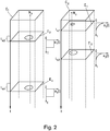
- Fig. 2 shows the further processing of events or occurring intensity values over time.
- Fig. 3 shows the individual event values occurring in the common map as well as the detection of a critical event.
- the Fig. 4a and 4b show the individual event values that result from accumulation in the first or in the second event card.
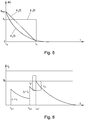
- Fig. 5 shows a variety of different possible decay behavior.
- Fig. 6 shows a possible, alternative embodiment of the invention with different specifications for determining the decay behavior.
- Fig. 7a shows a concrete application of a method according to the invention for the detection of critical events in larger crowds in public space.
- Fig. 7b shows a captured in the course of this application digital image of an image sensor.
- Sensors S 1 , S 2 are shown, each of which supplies sensor readings m 1 , m 2 continuously at predetermined times, ie recurring.
- the sensors S 1 , S 2 are a camera S 2 on the one hand and two microphone pairs S 1 arranged jointly at a predetermined distance on the other hand.
- the camera S 2 provides sensor readings in the form of digital images.
- the camera S 2 can be a thermal imaging camera or a camera that is sensitive to the visible range.
- the two microphone pairs S 1 supply sensor measured values as noise images, wherein the image areas or pixels of the noise image are each assigned intensity values which correspond to the probability that from a specific point in the recording area of both pairs of microphone S 1 Noise goes out.
- the concrete creation of the noise images is for example in Friedlander, B .: A passive localization algorithm and its accuracy analysis. In: Oceanic Engineering, IEEE Journal of 12 (1987), No. 1, pp. 234-245 described in more detail. In this case, a spatially localization of the received noise is made due to the differences in transit time of the microphones assigned to each other.
- a measure of conformity can be determined for the generation of events E 1 , E 2 , E 3 , E 4 , which indicates to what extent a detected noise matches or is similar to one or more reference noises.
- this match measure may represent an event in another event map that has intensity values within a radius around the microphone that correspond to the range of the microphone. The individual measured values are ultimately distributed to a large number of nodes.
- sensors S 1 , S 2 are basically freely definable and adaptable to the critical events to be detected.
- acoustic sensors such as microphones, directional microphones, floor vibration sensors or ODTR sensors can also be used to detect acoustic events that indicate critical events.
- cameras S 2 are used with different sensitivity for individual wavelength ranges. Typical in this context are cameras S 2 with sensitivity for the visible range, whereby normally gray scale cameras as well as RGB color cameras are used. In addition, however, other cameras S 2 such as infrared cameras or thermal imaging cameras can be used.
- door and window contacts or glass breakage sensors can be used to detect events related to specific buildings. If the movements of persons, vehicles or animals are to be observed, movement detectors or motion detectors can also be used within the scope of the invention.
- sensors that monitor communication via WLAN and Bluetooth can also be used to determine persons and paths traveled by these persons.
- microwave radar as a sensor for the detection of persons, animals or things, with such a sensor, a spatial intensity distribution can be determined.
- the event maps C 1 , C 2 shown are substantially in the form of a two-dimensional array of values that can also be interpreted as a digital image having a plurality of channels.
- the individual nodes N x , N y are arranged in a two-dimensional regular position which can be defined by two coordinate values, in particular in a grid-like manner with a grid with rows and columns.
- the individual nodes N x , N y the Event cards C 1 , C 2 can each be assigned values, possibly in several channels.
- At least a plurality of the nodes N x , N y, in particular each of the nodes N x , N y of the event cards C 1 , C 2, is associated with at least one region in the measuring range of at least one of the sensors S 1 , S 2 .
- the individual noise measurement values m 1 of the noise sensor or of the two microphone pairs S 1 are each assigned to a measurement range in relation to which the respective noise measurement value is determined.
- the individual measured values m 2 of the camera S 2 are each assigned a visual ray or visual cone of a pixel sensor of a camera S 2 .
- the respective visual ray or visual cone of a pixel sensor represents a partial region of the receiving region of the camera S 2 .
- sensors S 1 , S 2 provide sensor measured values m 1 , m 2 for a single event card C 1 , C 2 .
- the measuring ranges of the individual sensors S 1 , S 2 may well overlap, so that individual nodes of an event card C 1 , C 2 may be assigned a plurality of measured values which originate from the same measuring range.
- the sensor measured values of one or more sensors may be used in the formation of a plurality of event cards.
- the two sensors S 1 , S 2 are positioned such that they represent the same scene with different sensitivity from different spatial directions partially overlapping, so that individual measuring ranges of the two sensors S 1 , S 2 show measured values with respect to the same scene from different angles , Due to the knowledge of the specific orientation of the two sensors S 1 , S 2 , it is it is possible to associate readings taken with respect to the same recording area, to the same node of an event map.
- the pickup area of an image sensor of a camera S 2 positioned in an interior can be assumed to be the area that the camera S 2 picks up when there are no objects in the pickup area.
- the region of the first event map C 1 for which measured values m 1 are present is designated by the reference symbol C 1 '.
- the region of the second event map C 2 for which measured values m 2 are present is designated by the reference symbol C 2 '.
- the event cards C 1 , C 2 are merged to form a common card C, with a map T 1 , T 2 being provided for each event card C 1 , C 2 individual event maps C 1 , C 2 maps to the common map C.
- the event cards C 1 , C 2 are formed overlapping, so that at least two nodes N x , Nyder two different event cards C 1 , C 2 are each mapped to the same node M z of the common card C.
- this requirement does not have to be fulfilled for all points of an event card C 1 , C 2 and also not for all points of the common card C.
- each of these event cards in each case overlaps in at least one of its nodes N x , N y with another event card, so that for each event card there is at least one node N x which the same node M z of the common map C is mapped as at least one node N y another event map.
- the images of the individual event maps under the respective transformations T 1 , T 2 used result in a contiguous area on the common map C, ie, that not individual images T 1 (C 1 ), T 2 (C 2 ) of the event cards C 1 , C 2 under the respective Transformation transformations T 1 , T 2 do not overlap with any of the remaining images T 1 (C 1 ), T 2 (C 2 ) of the event maps.
- the common card C is given a number of nodes M z .
- the nodes M z of the common card C can preferably be arranged in grid form, in particular in a grid with rows and columns.
- the individual transformations T 1 , T 2 are selected in particular such that they map measured values relating to the same measuring range or overlapping measuring ranges to the same nodes M z of the common card C.
- the images T 1 , T 2 may also have a certain continuity or continuity such that measured values relating to adjacent measuring ranges are mapped onto adjacent nodes of the common card C.
- an interpolation can also be used since, in connection with the invention, it is by no means required that the nodes of the event maps C 1 , C 2 be represented exactly by the maps T 1 , T 2 on nodes of the common Map C can be mapped. Rather, there is also the possibility that the values of individual nodes of the event cards C 1 , C 2 are mapped to a plurality of nodes of the common card C. Conversely, for the determination of values on nodes of the common map C, several nodes of the event maps C 1 , C 2 adjacent to the archimage of the relevant node of the maps T 1 , T 2 can also be used. Different interpolation methods known from the prior art can be used for this purpose.
- Fig. 7a and 7b shown scene used closer.
- the image created by the camera S 2 is in Fig. 7b shown in more detail and shows on the one hand a not considered dangerous passers-I and an applied noisy crowd II people a total of seven people potentially posing a threat to public space.
- Fig. 7a shows the transformed event cards C 1 , C 2 and the common card C shown above each other, the event cards C 1 , C 2 according to their associated transformations T 1 , T 2 are already distorted such that superimposed points each other due to the transformations T 1 , T 2 are assigned.
- the in Fig. 7a vertically represented cylinder cuts in the two event maps C 1 , C 2 and in the common map C those areas that are affected by the human population II.
- different detection rules can be used for the detection of events.
- searching for events in the camera images created by the camera S 2 it is possible to identify moving persons in the camera image by means of pattern matching methods.
- the probability can be determined whether a person in the one of the event map C 2 associated measuring range of Camera S 2 is located.
- an event E 1 , E 2 , E 3 , E 4 can be determined or determined for the relevant time t a, 1 , t a, 2 , t a, 3 , t a, 4 , wherein the relevant event E 1 , E 2 , E 3 , E 4 is evaluated in its intensity by a number of intensity values assigned in each case to one node.
- the probability can be determined whether a sound source with a a Threshold exceeding sound level in the one node of the event card C 1 associated measuring range of the two microphone pairs S 1 is located.
- the intensity value respectively assigned to the event is weighted in particular with the intensity or volume of the noise.
- the attenuation of the signal caused by the distance of the area assigned to the node to the microphone can also be compensated.
- the event E 1 , E 2 , E 3 , E 4 is assigned a number of intensity values I assigned in each case to one node, which indicate the intensity of the event E 1 , E 2 , E 3 , E 4 in the relevant measuring range assigned to the node.
- the criteria by which events E 1 , E 2 , E 3 , E 4 are detected and identified can be chosen differently depending on the application and the type of sensor S 1 , S 2 concerned. In particular, it is also possible to separate the same event map C 1, C 2 assigned sensors S 1, S 2 with respect to their sensor measurements m 1, m 2 to link with each other.
- N y associated intensity values I each of the events E 1 , E 2 , E 3 , E 4 in addition assigned a decay function, which indicates over which period of time the relevant event E 1 , E 2 , E 3 , E 4 should be effective in the future.
- the individual sensor measured values determined need not necessarily be assigned to individual recording times t a, 1 , t a, 2 , t a, 3 , t a, 4 in order to be able to classify their temporal occurrence.
- recording periods can also be used in order to relate the individual sensor measured values to the other sensor measured values in time and to calculate the decay processes.
- the decay function determines a temporal decay behavior, ie the effect of the event for the future in the determination of critical events. This is, as already mentioned, dependent on the type of the respective event E 1 , E 2 , E 3 , E 4 .
- the decay function has a predetermined neutral value, in the present case 0, when a predetermined time interval t c is exceeded after the time t a of the respective event. If a convergent decay behavior is desired, the decay function can also converge to this neutral value, in this case 0.
- a first type of decay function a 1 (t) is constant for a period between the time t a of the respective event and an end time t c and has the value a c . After this time, it has the neutral value 0.
- a second type of decay function a 2 (t) falls to the neutral value 0 for a period of time from a predetermined maximum value a max between the time t a of the respective event and an end time t c with a linear progression has the neutral value 0.
- a third type of decay function a 3 (t) decreases exponentially from a predefined maximum value a max and, at the end time t c, has a value a 3 (t c ) which is almost at the neutral value 0, for example a 3 (t a ) / a 3 (t c ) ⁇ 0.01.
- the decay function never exactly reaches the neutral value 0.
- the decay behavior can also be modified by the duration of the recording period concerned.
- the time interval between the times t a and t c of the decay function are determined by the duration of the recording period.
- the function it is possible for the function to also increase after the time t a of the event E 1 , E 2 , E 3 , E 4 for a specific time range. After this time range, however, the function converges monotonically to the neutral value 0.
- a total of four events E 1 , E 2 , E 3 , E 4 are shown, wherein for each of the events in each case an event time t a, 1 , t a, 3 or an event time t a, 2 , t a, 4 is assigned.
- the event in question is assigned intensity values which have a value different from the neutral value 0 in the circled areas.
- the two events E 2 and E 4 of the first event card C 1 each associated with a decay function with a rectangular course
- the two events E 1 and E 3 of the second event card C 2 each associated with a decay function with exponential decay.
- node-by-node event values are formed by accumulating the individual intensity values, weighted by the same node of the event card C 1 , C 2 with a predetermined accumulation rule, and thus determining the event value.
- the accumulation rule also defines the neutral value used in the decay functions. Since the accumulation rule uses the, at best, weighted addition, in this preferred embodiment the value zero (0) is used as the neutral value, which represents the neutral element in terms of addition and does not change the result of an accumulation. If the multiplication is used as the accumulation rule, then the neutral value used is the value (1) which, in terms of multiplication, represents the neutral element and does not change the result of an accumulation.
- the accumulation runs in two stages when determining the event values V z .
- node-by-node event values V z were formed for all nodes N x , N y of the event cards C 1 , C 2 by the individual intensity values from the same node of the event card being weighted with a predetermined accumulation rule and thus the event value for the nodes N x , N y of the event cards C 1 , C 2 has been determined.
- a second step ( Fig. 3 ) , the individual event values V z of those nodes of the event card C 1 , C 2 , which were mapped to the respective node M z of the common card C or used for interpolation on the basis of the mapping T 1 , T 2 , with the same accumulation rule, namely by adding, accumulating and thus determining an event value V z for the node M z of the common card C.
- This procedure has the significant advantage that almost any decay functions and decay behavior of events can be used and individually adapted to the respective application.
- the same exponential decay function a 3 (t) is assigned to all, which decays exponentially with time after a predetermined half-life.
- the same exponential decay function a 3 (t) is assigned to all, which decays exponentially with time after a predetermined half-life.
- the event value V z of the relevant node or nodes M z of the common map C is increased by the intensity value or a value corresponding to the interpolation of the intensity value.
- the contributions J which provide the intensity values I of the events E 1 , E 2 , E 3 , E 4 for accumulation, are each weighted with a value that corresponds to the result of the application of the respective decay function of the respective event on the time period t d -t a between the detection time t d and the recording time t a or the recording period of the event E 1 , E 2 , E 3 , E 4 corresponds.
- the above methods need not be applied to the entire common card C. If for certain areas the occurrence of a critical event EK can be excluded, some areas of the common map C need not be treated at all. This can significantly speed up the numerical determination of critical events in the relevant areas.
- a sensor (not shown) is used to track people or objects. If a person has moved along a path on the event map and this has been detected, an event with a very long decay time can be determined, for which a given intensity value is set in each case over the entire movement path.
Landscapes
- Engineering & Computer Science (AREA)
- Theoretical Computer Science (AREA)
- Physics & Mathematics (AREA)
- General Physics & Mathematics (AREA)
- Multimedia (AREA)
- Data Mining & Analysis (AREA)
- Life Sciences & Earth Sciences (AREA)
- Artificial Intelligence (AREA)
- Bioinformatics & Cheminformatics (AREA)
- Bioinformatics & Computational Biology (AREA)
- Computer Vision & Pattern Recognition (AREA)
- Evolutionary Biology (AREA)
- Evolutionary Computation (AREA)
- General Engineering & Computer Science (AREA)
- Testing Or Calibration Of Command Recording Devices (AREA)
Applications Claiming Priority (2)
| Application Number | Priority Date | Filing Date | Title |
|---|---|---|---|
| AT500442017 | 2017-01-24 | ||
| AT500462017 | 2017-01-24 |
Publications (2)
| Publication Number | Publication Date |
|---|---|
| EP3352111A1 true EP3352111A1 (fr) | 2018-07-25 |
| EP3352111B1 EP3352111B1 (fr) | 2021-08-11 |
Family
ID=61027433
Family Applications (1)
| Application Number | Title | Priority Date | Filing Date |
|---|---|---|---|
| EP18151988.5A Active EP3352111B1 (fr) | 2017-01-24 | 2018-01-17 | Procédé de détection d'événements critiques |
Country Status (1)
| Country | Link |
|---|---|
| EP (1) | EP3352111B1 (fr) |
Cited By (1)
| Publication number | Priority date | Publication date | Assignee | Title |
|---|---|---|---|---|
| CN110890977A (zh) * | 2019-10-15 | 2020-03-17 | 平安科技(深圳)有限公司 | 云平台的主机节点监控方法、装置和计算机设备 |
-
2018
- 2018-01-17 EP EP18151988.5A patent/EP3352111B1/fr active Active
Non-Patent Citations (5)
| Title |
|---|
| AHMED DEWAN TANVIR ET AL: "Utility based decision support engine for camera view selection in multimedia surveillance systems", MULTIMEDIA TOOLS AND APPLICATIONS, KLUWER ACADEMIC PUBLISHERS, BOSTON, US, vol. 73, no. 1, 16 December 2012 (2012-12-16), pages 219 - 240, XP035396050, ISSN: 1380-7501, [retrieved on 20121216], DOI: 10.1007/S11042-012-1294-7 * |
| FRIEDLANDER, B.: "A passive localization algorithm and its accuracy analysis", OCEANIC ENGINEERING, IEEE JOURNAL OF, vol. 12, no. 1, 1987, pages 234 - 245, XP011290798 |
| JIANGFAN FENG ET AL: "Survey on Modeling and Detection Events in Georeferenced Multimedia Fusion", RECENT PATENTS ON COMPUTER SCIENCE, vol. 9, 1 January 2016 (2016-01-01), pages 241 - 247, XP055484078, DOI: 10.2174/22132759089991507221659 * |
| JÜRGEN BOHN ET AL: "Robust probabilistic positioning based on high-level sensor-fusion and map knowledge", TECHNICAL REPORT NO. 421, 18 April 2003 (2003-04-18), XP055484083, Retrieved from the Internet <URL:https://www.research-collection.ethz.ch/bitstream/handle/20.500.11850/68776/eth-4618-01.pdf?sequence=1&isAllowed=y> [retrieved on 20180613], DOI: 10.3929/ethz-a-006714680 * |
| KOOIJ J F P ET AL: "Multi-modal human aggression detection", COMPUTER VISION AND IMAGE UNDERSTANDING, ACADEMIC PRESS, US, vol. 144, 1 April 2016 (2016-04-01), pages 106 - 120, XP029400283, ISSN: 1077-3142, DOI: 10.1016/J.CVIU.2015.06.009 * |
Cited By (1)
| Publication number | Priority date | Publication date | Assignee | Title |
|---|---|---|---|---|
| CN110890977A (zh) * | 2019-10-15 | 2020-03-17 | 平安科技(深圳)有限公司 | 云平台的主机节点监控方法、装置和计算机设备 |
Also Published As
| Publication number | Publication date |
|---|---|
| EP3352111B1 (fr) | 2021-08-11 |
Similar Documents
| Publication | Publication Date | Title |
|---|---|---|
| EP2297701B1 (fr) | Analyse vidéo | |
| DE602005003926T2 (de) | System und verfahren zum erkennen eines vorbeikommenden fahrzeugs aus dynamischem hintergrund unter verwendung robuster informationsfusion | |
| EP1531342B1 (fr) | Procédé de détection des piétons | |
| DE102007001649A1 (de) | Verfahren, Vorrichtung und Computerprogramm zur Selbstkalibrierung einer Überwachungskamera | |
| DE102020203796B4 (de) | Verfahren und Vorrichtung zum Bestimmen einer Messinformation und LiDAR-Gerät | |
| WO2009003793A2 (fr) | Dispositif pour identifier et/ou classifier des modèles de mouvements dans une séquence d'images d'une scène de surveillance, procédé et programme informatique | |
| EP2553660B1 (fr) | Procédé pour visualiser des zones d'activité accrue dans des scènes de surveillance | |
| WO2012110653A1 (fr) | Procédé de détection d'objets cibles dans une zone de surveillance | |
| WO2019120611A1 (fr) | Procédé de vérification de l'appartenance de noeuds radio à un environnement radio, par une évaluation de fractions de signaux perturbateurs | |
| EP1927866A1 (fr) | Procédé de traitement de signaux de capteur basé sur une grille | |
| EP2875498B1 (fr) | Système de surveillance à zone de protection dépendante de la position, procédé de surveillance d'une zone à surveiller et programme informatique | |
| DE102014208272A1 (de) | Verfahren und Vorrichtung zur Tracking-basierten Sichtweitenschätzung | |
| EP3663881B1 (fr) | Procédé de commande d'un véhicule autonome en fonction des vecteurs de mouvement estimés | |
| DE102016225806A1 (de) | Verfahren zur Erfassung und Klassifizierung von Objekten | |
| EP3557549A1 (fr) | Procédé d'évaluation d'un événement de mouvement | |
| EP3352111B1 (fr) | Procédé de détection d'événements critiques | |
| DE102009026091A1 (de) | Verfahren und System zur Überwachung eines dreidimensionalen Raumbereichs mit mehreren Kameras | |
| DE102007041333B4 (de) | Berührungslos arbeitendes Zählsystem | |
| DE112022002520T5 (de) | Verfahren zur automatischen Kalibrierung von Kameras und Erstellung von Karten | |
| EP3021256A1 (fr) | Procede de traitement d'images, detecteur de presence et systeme d'eclairage | |
| EP3663800B1 (fr) | Procédé de détection d'objet à l'aide d'une camera tridimensionnelle | |
| DE102018117274A1 (de) | Sichere Kamera und Verfahren zur sicheren Aufnahme und Auswertung von Bilddaten | |
| EP4556944A1 (fr) | Procédé mis en uvre par ordinateur pour mesurer et surveiller des paramètres vitaux et détecter des situations d'urgence et de chute dans une zone de surveillance à l'aide d'un réseau de capteurs | |
| DE102008057176B4 (de) | Automatisierbares 3D-Rekonstruktionsverfahren und Überwachungsvorrichtung | |
| AT520863B1 (de) | Verfahren zur Detektion von Körperbewegungen einer schlafenden Person |
Legal Events
| Date | Code | Title | Description |
|---|---|---|---|
| PUAI | Public reference made under article 153(3) epc to a published international application that has entered the european phase |
Free format text: ORIGINAL CODE: 0009012 |
|
| STAA | Information on the status of an ep patent application or granted ep patent |
Free format text: STATUS: THE APPLICATION HAS BEEN PUBLISHED |
|
| AK | Designated contracting states |
Kind code of ref document: A1 Designated state(s): AL AT BE BG CH CY CZ DE DK EE ES FI FR GB GR HR HU IE IS IT LI LT LU LV MC MK MT NL NO PL PT RO RS SE SI SK SM TR |
|
| AX | Request for extension of the european patent |
Extension state: BA ME |
|
| STAA | Information on the status of an ep patent application or granted ep patent |
Free format text: STATUS: REQUEST FOR EXAMINATION WAS MADE |
|
| 17P | Request for examination filed |
Effective date: 20181128 |
|
| RBV | Designated contracting states (corrected) |
Designated state(s): AL AT BE BG CH CY CZ DE DK EE ES FI FR GB GR HR HU IE IS IT LI LT LU LV MC MK MT NL NO PL PT RO RS SE SI SK SM TR |
|
| STAA | Information on the status of an ep patent application or granted ep patent |
Free format text: STATUS: EXAMINATION IS IN PROGRESS |
|
| 17Q | First examination report despatched |
Effective date: 20200721 |
|
| GRAP | Despatch of communication of intention to grant a patent |
Free format text: ORIGINAL CODE: EPIDOSNIGR1 |
|
| STAA | Information on the status of an ep patent application or granted ep patent |
Free format text: STATUS: GRANT OF PATENT IS INTENDED |
|
| INTG | Intention to grant announced |
Effective date: 20210318 |
|
| GRAS | Grant fee paid |
Free format text: ORIGINAL CODE: EPIDOSNIGR3 |
|
| GRAA | (expected) grant |
Free format text: ORIGINAL CODE: 0009210 |
|
| STAA | Information on the status of an ep patent application or granted ep patent |
Free format text: STATUS: THE PATENT HAS BEEN GRANTED |
|
| AK | Designated contracting states |
Kind code of ref document: B1 Designated state(s): AL AT BE BG CH CY CZ DE DK EE ES FI FR GB GR HR HU IE IS IT LI LT LU LV MC MK MT NL NO PL PT RO RS SE SI SK SM TR |
|
| REG | Reference to a national code |
Ref country code: CH Ref legal event code: EP |
|
| REG | Reference to a national code |
Ref country code: DE Ref legal event code: R096 Ref document number: 502018006482 Country of ref document: DE |
|
| REG | Reference to a national code |
Ref country code: IE Ref legal event code: FG4D Free format text: LANGUAGE OF EP DOCUMENT: GERMAN Ref country code: AT Ref legal event code: REF Ref document number: 1420135 Country of ref document: AT Kind code of ref document: T Effective date: 20210915 |
|
| REG | Reference to a national code |
Ref country code: DE Ref legal event code: R079 Ref document number: 502018006482 Country of ref document: DE Free format text: PREVIOUS MAIN CLASS: G06K0009000000 Ipc: G06V0010000000 |
|
| REG | Reference to a national code |
Ref country code: LT Ref legal event code: MG9D |
|
| REG | Reference to a national code |
Ref country code: NL Ref legal event code: MP Effective date: 20210811 |
|
| PG25 | Lapsed in a contracting state [announced via postgrant information from national office to epo] |
Ref country code: RS Free format text: LAPSE BECAUSE OF FAILURE TO SUBMIT A TRANSLATION OF THE DESCRIPTION OR TO PAY THE FEE WITHIN THE PRESCRIBED TIME-LIMIT Effective date: 20210811 Ref country code: SE Free format text: LAPSE BECAUSE OF FAILURE TO SUBMIT A TRANSLATION OF THE DESCRIPTION OR TO PAY THE FEE WITHIN THE PRESCRIBED TIME-LIMIT Effective date: 20210811 Ref country code: FI Free format text: LAPSE BECAUSE OF FAILURE TO SUBMIT A TRANSLATION OF THE DESCRIPTION OR TO PAY THE FEE WITHIN THE PRESCRIBED TIME-LIMIT Effective date: 20210811 Ref country code: ES Free format text: LAPSE BECAUSE OF FAILURE TO SUBMIT A TRANSLATION OF THE DESCRIPTION OR TO PAY THE FEE WITHIN THE PRESCRIBED TIME-LIMIT Effective date: 20210811 Ref country code: HR Free format text: LAPSE BECAUSE OF FAILURE TO SUBMIT A TRANSLATION OF THE DESCRIPTION OR TO PAY THE FEE WITHIN THE PRESCRIBED TIME-LIMIT Effective date: 20210811 Ref country code: PT Free format text: LAPSE BECAUSE OF FAILURE TO SUBMIT A TRANSLATION OF THE DESCRIPTION OR TO PAY THE FEE WITHIN THE PRESCRIBED TIME-LIMIT Effective date: 20211213 Ref country code: NO Free format text: LAPSE BECAUSE OF FAILURE TO SUBMIT A TRANSLATION OF THE DESCRIPTION OR TO PAY THE FEE WITHIN THE PRESCRIBED TIME-LIMIT Effective date: 20211111 Ref country code: BG Free format text: LAPSE BECAUSE OF FAILURE TO SUBMIT A TRANSLATION OF THE DESCRIPTION OR TO PAY THE FEE WITHIN THE PRESCRIBED TIME-LIMIT Effective date: 20211111 Ref country code: LT Free format text: LAPSE BECAUSE OF FAILURE TO SUBMIT A TRANSLATION OF THE DESCRIPTION OR TO PAY THE FEE WITHIN THE PRESCRIBED TIME-LIMIT Effective date: 20210811 |
|
| PG25 | Lapsed in a contracting state [announced via postgrant information from national office to epo] |
Ref country code: PL Free format text: LAPSE BECAUSE OF FAILURE TO SUBMIT A TRANSLATION OF THE DESCRIPTION OR TO PAY THE FEE WITHIN THE PRESCRIBED TIME-LIMIT Effective date: 20210811 Ref country code: LV Free format text: LAPSE BECAUSE OF FAILURE TO SUBMIT A TRANSLATION OF THE DESCRIPTION OR TO PAY THE FEE WITHIN THE PRESCRIBED TIME-LIMIT Effective date: 20210811 Ref country code: GR Free format text: LAPSE BECAUSE OF FAILURE TO SUBMIT A TRANSLATION OF THE DESCRIPTION OR TO PAY THE FEE WITHIN THE PRESCRIBED TIME-LIMIT Effective date: 20211112 |
|
| PG25 | Lapsed in a contracting state [announced via postgrant information from national office to epo] |
Ref country code: NL Free format text: LAPSE BECAUSE OF FAILURE TO SUBMIT A TRANSLATION OF THE DESCRIPTION OR TO PAY THE FEE WITHIN THE PRESCRIBED TIME-LIMIT Effective date: 20210811 |
|
| PG25 | Lapsed in a contracting state [announced via postgrant information from national office to epo] |
Ref country code: DK Free format text: LAPSE BECAUSE OF FAILURE TO SUBMIT A TRANSLATION OF THE DESCRIPTION OR TO PAY THE FEE WITHIN THE PRESCRIBED TIME-LIMIT Effective date: 20210811 |
|
| PGFP | Annual fee paid to national office [announced via postgrant information from national office to epo] |
Ref country code: DE Payment date: 20220119 Year of fee payment: 5 |
|
| REG | Reference to a national code |
Ref country code: DE Ref legal event code: R097 Ref document number: 502018006482 Country of ref document: DE |
|
| PG25 | Lapsed in a contracting state [announced via postgrant information from national office to epo] |
Ref country code: SM Free format text: LAPSE BECAUSE OF FAILURE TO SUBMIT A TRANSLATION OF THE DESCRIPTION OR TO PAY THE FEE WITHIN THE PRESCRIBED TIME-LIMIT Effective date: 20210811 Ref country code: SK Free format text: LAPSE BECAUSE OF FAILURE TO SUBMIT A TRANSLATION OF THE DESCRIPTION OR TO PAY THE FEE WITHIN THE PRESCRIBED TIME-LIMIT Effective date: 20210811 Ref country code: RO Free format text: LAPSE BECAUSE OF FAILURE TO SUBMIT A TRANSLATION OF THE DESCRIPTION OR TO PAY THE FEE WITHIN THE PRESCRIBED TIME-LIMIT Effective date: 20210811 Ref country code: EE Free format text: LAPSE BECAUSE OF FAILURE TO SUBMIT A TRANSLATION OF THE DESCRIPTION OR TO PAY THE FEE WITHIN THE PRESCRIBED TIME-LIMIT Effective date: 20210811 Ref country code: CZ Free format text: LAPSE BECAUSE OF FAILURE TO SUBMIT A TRANSLATION OF THE DESCRIPTION OR TO PAY THE FEE WITHIN THE PRESCRIBED TIME-LIMIT Effective date: 20210811 Ref country code: AL Free format text: LAPSE BECAUSE OF FAILURE TO SUBMIT A TRANSLATION OF THE DESCRIPTION OR TO PAY THE FEE WITHIN THE PRESCRIBED TIME-LIMIT Effective date: 20210811 |
|
| PLBE | No opposition filed within time limit |
Free format text: ORIGINAL CODE: 0009261 |
|
| STAA | Information on the status of an ep patent application or granted ep patent |
Free format text: STATUS: NO OPPOSITION FILED WITHIN TIME LIMIT |
|
| 26N | No opposition filed |
Effective date: 20220512 |
|
| PG25 | Lapsed in a contracting state [announced via postgrant information from national office to epo] |
Ref country code: IT Free format text: LAPSE BECAUSE OF FAILURE TO SUBMIT A TRANSLATION OF THE DESCRIPTION OR TO PAY THE FEE WITHIN THE PRESCRIBED TIME-LIMIT Effective date: 20210811 |
|
| PG25 | Lapsed in a contracting state [announced via postgrant information from national office to epo] |
Ref country code: SI Free format text: LAPSE BECAUSE OF FAILURE TO SUBMIT A TRANSLATION OF THE DESCRIPTION OR TO PAY THE FEE WITHIN THE PRESCRIBED TIME-LIMIT Effective date: 20210811 Ref country code: MC Free format text: LAPSE BECAUSE OF FAILURE TO SUBMIT A TRANSLATION OF THE DESCRIPTION OR TO PAY THE FEE WITHIN THE PRESCRIBED TIME-LIMIT Effective date: 20210811 |
|
| REG | Reference to a national code |
Ref country code: CH Ref legal event code: PL |
|
| GBPC | Gb: european patent ceased through non-payment of renewal fee |
Effective date: 20220117 |
|
| REG | Reference to a national code |
Ref country code: BE Ref legal event code: MM Effective date: 20220131 |
|
| PG25 | Lapsed in a contracting state [announced via postgrant information from national office to epo] |
Ref country code: LU Free format text: LAPSE BECAUSE OF NON-PAYMENT OF DUE FEES Effective date: 20220117 Ref country code: GB Free format text: LAPSE BECAUSE OF NON-PAYMENT OF DUE FEES Effective date: 20220117 |
|
| PG25 | Lapsed in a contracting state [announced via postgrant information from national office to epo] |
Ref country code: FR Free format text: LAPSE BECAUSE OF NON-PAYMENT OF DUE FEES Effective date: 20220131 Ref country code: BE Free format text: LAPSE BECAUSE OF NON-PAYMENT OF DUE FEES Effective date: 20220131 |
|
| PG25 | Lapsed in a contracting state [announced via postgrant information from national office to epo] |
Ref country code: LI Free format text: LAPSE BECAUSE OF NON-PAYMENT OF DUE FEES Effective date: 20220131 Ref country code: CH Free format text: LAPSE BECAUSE OF NON-PAYMENT OF DUE FEES Effective date: 20220131 |
|
| PG25 | Lapsed in a contracting state [announced via postgrant information from national office to epo] |
Ref country code: IE Free format text: LAPSE BECAUSE OF NON-PAYMENT OF DUE FEES Effective date: 20220117 |
|
| REG | Reference to a national code |
Ref country code: DE Ref legal event code: R119 Ref document number: 502018006482 Country of ref document: DE |
|
| PG25 | Lapsed in a contracting state [announced via postgrant information from national office to epo] |
Ref country code: DE Free format text: LAPSE BECAUSE OF NON-PAYMENT OF DUE FEES Effective date: 20230801 |
|
| REG | Reference to a national code |
Ref country code: AT Ref legal event code: MM01 Ref document number: 1420135 Country of ref document: AT Kind code of ref document: T Effective date: 20230117 |
|
| PG25 | Lapsed in a contracting state [announced via postgrant information from national office to epo] |
Ref country code: HU Free format text: LAPSE BECAUSE OF FAILURE TO SUBMIT A TRANSLATION OF THE DESCRIPTION OR TO PAY THE FEE WITHIN THE PRESCRIBED TIME-LIMIT; INVALID AB INITIO Effective date: 20180117 |
|
| PG25 | Lapsed in a contracting state [announced via postgrant information from national office to epo] |
Ref country code: AT Free format text: LAPSE BECAUSE OF NON-PAYMENT OF DUE FEES Effective date: 20230117 |
|
| PG25 | Lapsed in a contracting state [announced via postgrant information from national office to epo] |
Ref country code: MK Free format text: LAPSE BECAUSE OF FAILURE TO SUBMIT A TRANSLATION OF THE DESCRIPTION OR TO PAY THE FEE WITHIN THE PRESCRIBED TIME-LIMIT Effective date: 20210811 Ref country code: CY Free format text: LAPSE BECAUSE OF FAILURE TO SUBMIT A TRANSLATION OF THE DESCRIPTION OR TO PAY THE FEE WITHIN THE PRESCRIBED TIME-LIMIT Effective date: 20210811 Ref country code: AT Free format text: LAPSE BECAUSE OF NON-PAYMENT OF DUE FEES Effective date: 20230117 |
|
| PG25 | Lapsed in a contracting state [announced via postgrant information from national office to epo] |
Ref country code: TR Free format text: LAPSE BECAUSE OF FAILURE TO SUBMIT A TRANSLATION OF THE DESCRIPTION OR TO PAY THE FEE WITHIN THE PRESCRIBED TIME-LIMIT Effective date: 20210811 |
|
| PG25 | Lapsed in a contracting state [announced via postgrant information from national office to epo] |
Ref country code: MT Free format text: LAPSE BECAUSE OF FAILURE TO SUBMIT A TRANSLATION OF THE DESCRIPTION OR TO PAY THE FEE WITHIN THE PRESCRIBED TIME-LIMIT Effective date: 20210811 |
|
| PGFP | Annual fee paid to national office [announced via postgrant information from national office to epo] |
Ref country code: AT Payment date: 20260410 Year of fee payment: 5 |