EP3352149B1 - Machine avec un support de broche pour les marchandises - Google Patents
Machine avec un support de broche pour les marchandises Download PDFInfo
- Publication number
- EP3352149B1 EP3352149B1 EP18000007.7A EP18000007A EP3352149B1 EP 3352149 B1 EP3352149 B1 EP 3352149B1 EP 18000007 A EP18000007 A EP 18000007A EP 3352149 B1 EP3352149 B1 EP 3352149B1
- Authority
- EP
- European Patent Office
- Prior art keywords
- spindle
- drive
- vending machine
- article
- goods
- Prior art date
- Legal status (The legal status is an assumption and is not a legal conclusion. Google has not performed a legal analysis and makes no representation as to the accuracy of the status listed.)
- Active
Links
Images

Classifications
-
- G—PHYSICS
- G07—CHECKING-DEVICES
- G07F—COIN-FREED OR LIKE APPARATUS
- G07F11/00—Coin-freed apparatus for dispensing, or the like, discrete articles
- G07F11/02—Coin-freed apparatus for dispensing, or the like, discrete articles from non-movable magazines
- G07F11/04—Coin-freed apparatus for dispensing, or the like, discrete articles from non-movable magazines in which magazines the articles are stored one vertically above the other
- G07F11/16—Delivery means
- G07F11/24—Rotary or oscillatory members
-
- G—PHYSICS
- G07—CHECKING-DEVICES
- G07F—COIN-FREED OR LIKE APPARATUS
- G07F11/00—Coin-freed apparatus for dispensing, or the like, discrete articles
- G07F11/02—Coin-freed apparatus for dispensing, or the like, discrete articles from non-movable magazines
- G07F11/04—Coin-freed apparatus for dispensing, or the like, discrete articles from non-movable magazines in which magazines the articles are stored one vertically above the other
- G07F11/16—Delivery means
- G07F11/26—Endless bands
Definitions
- the invention is based on a vending machine according to the preamble of independent claim 1.
- the invention relates in a further aspect to a method for dispensing goods in a vending machine according to the preamble of independent claim 7.
- Such vending machines are used for dispensing goods in the Used near a checkout area.
- the DE 38 02 399 C2 shows a vending machine, which has a number of product chutes, all of which have their own goods issue area.
- a housing of such a vending machine has a limited scope for design. This in particular also limits the storage volume for goods stored in the vending machine.
- the GB 2 200 620 A shows a vending machine with several goods chutes, in each of which goods are stacked.
- Each goods shaft has a goods dispensing unit consisting of a rotating spindle and a motor that drives the spindle.
- the drive pulley of the spindle is in permanent contact with the motor.
- the DE 39 12 971 C1 shows a goods shaft for a vending machine. There are goods inside the goods shaft stacked on top of each other. An extension unit is provided below the goods shaft. With the help of the ejection unit, individual goods are ejected forwards perpendicular to the stacking direction.
- the DE 3 401 671 A1 shows a vending machine with an endless belt or chain or the like, which is stretched between the guide rollers. Two ejectors are attached to the belt, which alternately pivot around a shaft and push one of the stacked goods out of a shaft, formed from a front and a rear, sideways to an outlet.
- the WO 2004 114 233 A1 shows a vending machine with a vertical array in which the individual goods are stored.
- the vending machine has an xy conveyor that transports the goods to a central delivery area 6.
- the DE 20 2004 007 670 U1 shows a vending machine for products, especially pharmaceuticals.
- the vending machine has a dispensing unit with a dispensing opening, in the area of which the requested product can be placed by rotating the product receiving device about its axis of rotation.
- the US2007 / 0199951 A1 describes a vending machine which has compartments in which individual goods are stored one behind the other in spindles. Each spindle has a drive pulley. A chain is stretched around the individual drive sheaves, via which a single drive sheave can be selectively activated, as a result of which a single item is dispensed.
- the object of the invention is to propose a vending machine that is structurally flexible and adaptable to its place of use and at the same time has a large storage volume of goods.
- the object is solved by the subject matter of the independent claims.
- the vending machine according to the invention is equipped with a plurality of individual spindle rods.
- a plurality of individual goods is stored on the respective spindle rods.
- These are, for example, razor blade packs that are suspended on the respective spindle rod via a so-called Euroslot recess.
- the vending machine has a fixed goods issue area.
- This stationary goods issue area is also the only goods issue area that the vending machine has. All goods are issued here.
- the goods issue area is assigned to the customer.
- stationary means that the goods stored in the vending machine are always output at the same output area, regardless of the area in which the goods are stored in the vending machine. This enables the customer to orientate himself better.
- the vending machine can use space that is used for the placement of a further goods issue area, for example according to the DE 38 02 399 C2 would not be suitable.
- the individual spindle rods can be moved to the fixed goods issue area via a suitable drive.
- a conveyor chain consisting of individual chain links movably attached to one another is preferably used as the drive here.
- the individual spindle rods are preferably each attached to a chain link.
- the type of drive allows particularly flexible travels.
- the vending machine has a central, fixed spindle drive near the goods dispensing area. This allows the individual spindle rods to be rotated. This makes it unnecessary to equip each individual spindle rod with its own spindle drive. This saves weight what allows a high conveyor chain speed. The customer does not have to wait long for the desired goods, even if the required spindle rod is still relatively far from the fixed goods issue area.
- the individual spindle rods each have a drive disk.
- the drive disk extends in the radial direction of the spindle rod and is aligned perpendicular to the spindle rod.
- the spindle rod can be brought into the desired rotational movement via the drive disk.
- the peripheral surface of the drive pulley is preferably covered with a rubber material. With mechanical contact to the drive pulley, high friction coefficients can be achieved with the attacking body.
- the stationary spindle drive advantageously has at least one drive roller which can be brought into operative or contact contact with the drive disk of the respective spindle rod.
- two such drive rollers are provided.
- the drive roller or the drive rollers are pressed onto the drive disk of the respective spindle rod with a defined force.
- At least one drive roller is driven by an electric motor.
- the second drive roller only serves to stabilize a rotational movement.
- the drive rollers are set in a rotational movement which is transmitted to the drive pulley. This causes the respective spindle rod to rotate.
- a decentralized spindle rod arrangement and a central drive arrangement allow a particularly compact and inexpensive construction of the vending machine according to the invention.
- a support plate is preferably arranged below the individual spindle rods.
- the support plate stabilizes the suspension of the goods on the spindle rods and at the same time supports the guidance of the goods on the spindle rod.
- the vending machine has a camera which is arranged at the fixed goods delivery area.
- the individual goods and their position on the spindle rod can be recorded via the camera.
- the camera can detect, for example, when a product suspended on the spindle rod has been conveyed to the end of the spindle rod by the rotational movement of the spindle rod or has fallen off the spindle rod.
- the camera can also detect whether it is the goods requested by the customer.
- the delivery of goods requested by the customer proceeds as follows: First, the spindle rod, which carries the desired goods, is moved to a stationary goods delivery area using the conveyor chain. The spindle rod is then brought into a rotational movement by a central spindle drive arranged at the stationary goods delivery area. Due to the rotational movement of the spindle rod, the goods or the goods are conveyed axially forward in the direction of the free end of the spindle rod. There, the customer can then remove one or more desired goods from the spindle rod, for example.
- the goods or the goods are conveyed axially forward in the direction of the free end of the spindle rod by the rotational movement of the spindle rod until one product falls from the spindle rod or several products fall from the spindle rod.
- the output area can be designed in such a way that the fallen goods or the fallen goods fall from one Collecting container to be collected. The customer can then only access the goods in it and has no direct access to the respective spindle rod. This can prevent theft. The number of goods falling can be limited accordingly.
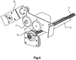
- the Figure 1 shows a perspective view of the drive area of a spindle rod 1.
- the drive area is located directly at the central goods issue area 12 of a vending machine 10.
- a support plate 2 is arranged below the spindle rod 1.
- the support plate 2 increases the load capacity of the spindle rod 1.
- the goods 3, 3 'attached to the spindle rod 1 are guided through the support plate 2 when the goods 3 are conveyed axially forward in the direction of the arrow 4.
- the spindle rod 1 projects above the support plate 2.
- a drive pulley 5 is formed or fastened on the spindle rod 1.
- the drive pulley 5 is made of metal.
- the peripheral surface of the drive disk 5 is covered with a rubber ring 6 in order to increase the coefficient of static friction with a friction partner accordingly.
- the drive roller 5 could also be made of plastic.
- the surface of this drive roller 5 could be roughened accordingly to optimize friction.
- the drive rollers 7, 7 'are made of metal.
- the circumferential surface of the drive rollers 7, 7 ' was each covered with a rubber ring.
- the drive rollers 7, 7 'can Electric motor 9 are driven.
- the rotational movement of the drive rollers 7, 7 ' is transmitted to the drive disk 5 by frictional engagement, as a result of which the spindle rod 1 is set into a rotational movement. Due to the rotational movement of the spindle rod 1, the goods 3, 3 'located thereon are transported to the free end of the spindle rod 1 in the direction of the arrow 4. This process can continue until a product 3 falls from the spindle rod 1.
- the falling of the goods 3 can be detected by a camera (not shown).
- the goods 3 then fall into a collecting container (not shown) which is accessible to the customer.
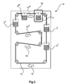
- FIG 3 the conveying principle of a vending machine 10 according to the invention can be seen.
- the goods 3, 3 ', 3 ", ... suspended on a spindle rod are conveyed through the vending machine 10 with the aid of a conveyor chain 11 - along the arrows 12, 12', 12", ...
- the conveyor chain 11 is driven by a gear 13.
- the conveyor chain 11 can also be conveyed backwards, ie counter to the direction of the arrow 12, 12 ', 12', ... This allows the shortest route to be chosen for the desired products.
- the goods 3 requested by a customer for example via an operating terminal (not shown), are conveyed to a central, stationary goods delivery area 12. In this case, only this goods issue area 12 must be accessible to the customer.
- the rest of the vending machine can be built on, for example by assembling at a checkout counter. In this way, for example, a vending machine integrated in a checkout counter can utilize unused space in the checkout counter.
Landscapes
- Physics & Mathematics (AREA)
- General Physics & Mathematics (AREA)
- Vending Machines For Individual Products (AREA)
- Control Of Vending Devices And Auxiliary Devices For Vending Devices (AREA)
Claims (8)
- Distributeur automatique (10) comprenant une pluralité de tiges de broche individuelles (1) sur lesquelles est à chaque fois supportée Une pluralité de marchandises individuelles (3, 3'), le distributeur automatique (10) présentant une région de sortie de marchandises fixe (12), les tiges de broche individuelles (1) pouvant être déplacées par le biais d'un entraînement approprié jusqu'à la région de sortie de marchandises fixe (12), le distributeur automatique (10) présentant, à proximité de la région de sortie de marchandises (12), un entraînement de broche fixe avec au moins un rouleau d'entraînement métallique (7), avec lequel une tige de broche (1) (1) se trouvant au niveau de la région de sortie de marchandises (12) peut être animée d'un mouvement de rotation pour délivrer les marchandises individuelles (3, 3'), les tiges de broche individuelles (1) présentant chacune un disque d'entraînement (5), l'au moins un rouleau d'entraînement (7) de l'entraînement de broche fixe pouvant être amené en contact fonctionnel avec le disque d'entraînement (5) de la tige de broche (1) se trouvant au niveau de la région de sortie de marchandises (12), par un aimant (8) disposé à proximité de la région de sortie de marchandises (12), lequel peut être déplacé vers l'au moins, un rouleau d'entraînement (7) et à l'écart du à l'au moins un rouleau d'entraînement (7).
- Distributeur automatique selon la revendication 1, dans lequel
l'entraînement de broche fixe présente au moins deux rouleaux d'entraînement (7, 7') qui peuvent être amenés en contact fonctionnel avec le disque d'entraînement (5) de la tige de broche respective (1) . - Distributeur automatique selon la revendication précédente 2, dans lequel
seulement l'un des deux rouleaux d'entraînement (7, 7') est entraîné par un moteur électrique. - Distributeur automatique selon l'une quelconque des revendications précédentes, dans lequel
une tôle de support (2) est à chaque fois disposée en dessous des tiges de broche individuelles (1). - Distributeur automatique selon l'une quelconque des revendications précédentes,
le distributeur automatique (10) présentant une chaîne transporteuse (11) sur laquelle sont fixées les tiges de broche individuelles (1). - Distributeur automatique selon l'une quelconque des revendications précédentes,
le distributeur automatique (10) présentant une caméra qui est disposée au niveau de la région de sortie de marchandises fixe (12). - Procédé pour délivrer une marchandise (3, 3'), dans un distributeur automatique (10), le distributeur automatique (10) présentant plusieurs tiges de broches (1) qui sont fixées à chaque fois sur une chaîne transporteuse (11),
plusieurs marchandises (3, 3') étant à chaque fois supportées sur les tiges de broche individuelles. (1),
les tiges de broche (1) étant déplacées à l'aide de la chaîne transporteuse (11) jusqu'à une région de sortie de marchandises fixe (12),
les tiges de broche individuelles (1) présentant chacune un disque d'entraînement (5) et une tige de broche (1) (1) se trouvant au niveau de la région de sortie de marchandises fixe (12) étant animée d'un mouvement de rotation par un entraînement de broche central disposé au niveau de la région de sortie de marchandises fixe (12), par le fait qu'au moins un rouleau d'entraînement métallique (7) de l'entraînement de broche fixe est amené en contact fonctionnel et est mis en rotation avec le disque d'entraînement (5) de la tige de broche respective (1), par un aimant (8) disposé à proximité de la région de sortie de marchandises (12), qui est déplacé à .chaque fois vers l'au moins un rouleau d'entraînement (7) et à l'écart de l'au moins un rouleau d'entraînement (7),
une marchandise (3) étant transportée axialement vers l'avant dans la direction de l'extrémité libre de la tige de broche (1) par le mouvement de rotation de la tige de broche (1). - Procédé pour délivrer une marchandise dans un distributeur automatique selon la revendication 7, dans lequel, par le mouvement de rotation de la tige de broche (1), une marchandise (3, 3') est transportée axialement vers l'avant dans la direction de l'extrémité libre de la tige de broche (1) jusqu'à ce que la marchandise (3, 3') tombe de la tige de broche (1).
Applications Claiming Priority (1)
| Application Number | Priority Date | Filing Date | Title |
|---|---|---|---|
| DE102017101125.0A DE102017101125A1 (de) | 2017-01-20 | 2017-01-20 | Warenautomat mit einer Spindelaufhängung für Waren |
Publications (2)
| Publication Number | Publication Date |
|---|---|
| EP3352149A1 EP3352149A1 (fr) | 2018-07-25 |
| EP3352149B1 true EP3352149B1 (fr) | 2020-04-29 |
Family
ID=60937602
Family Applications (1)
| Application Number | Title | Priority Date | Filing Date |
|---|---|---|---|
| EP18000007.7A Active EP3352149B1 (fr) | 2017-01-20 | 2018-01-04 | Machine avec un support de broche pour les marchandises |
Country Status (2)
| Country | Link |
|---|---|
| EP (1) | EP3352149B1 (fr) |
| DE (1) | DE102017101125A1 (fr) |
Family Cites Families (6)
| Publication number | Priority date | Publication date | Assignee | Title |
|---|---|---|---|---|
| DE3401671A1 (de) * | 1984-01-19 | 1985-07-25 | Georg 5275 Bergneustadt Prümm | Verkaufsautomat |
| GB2200620B (en) * | 1987-01-28 | 1990-08-15 | Wurlitzer Gmbh | Automatic vending machine |
| DE3912971C1 (fr) * | 1989-04-20 | 1990-01-11 | Harting Elektronik Gmbh, 4992 Espelkamp, De | |
| WO2004114233A1 (fr) * | 2003-06-15 | 2004-12-29 | Apollo Vending Services Ltd | Appareil de stockage et de recuperation d'articles et distributeur automatique |
| DE202004007670U1 (de) * | 2004-03-19 | 2004-07-29 | Professor Alfred Krauth Apparatebau Gmbh & Co. Kg | Ausgabeautomat für Produkte, insbesondere Arzneimittel |
| US7597214B2 (en) * | 2006-02-27 | 2009-10-06 | Coin Acceptors, Inc. | Product dispenser for a vending machine |
-
2017
- 2017-01-20 DE DE102017101125.0A patent/DE102017101125A1/de not_active Withdrawn
-
2018
- 2018-01-04 EP EP18000007.7A patent/EP3352149B1/fr active Active
Non-Patent Citations (1)
| Title |
|---|
| None * |
Also Published As
| Publication number | Publication date |
|---|---|
| EP3352149A1 (fr) | 2018-07-25 |
| DE102017101125A1 (de) | 2018-07-26 |
Similar Documents
| Publication | Publication Date | Title |
|---|---|---|
| DE4100769C2 (de) | Vorrichtung zum Fördern von Produkten in einer Verpackungsmaschine | |
| EP2353149B1 (fr) | Procédé et installation de transport pour le recyclage d'emballages vides en retour, en particulier de bouteilles et de boîtes | |
| EP3335201B1 (fr) | Dispositif de défournement de produits de boulangerie-pâtisserie | |
| DE102005058478A1 (de) | Einzelhandelversorgungssystem | |
| DE4015103A1 (de) | Vorrichtung zum ausrichten von gegenstaenden, insbesonders zur beschickung von einwickelmaschinen | |
| EP3225571B1 (fr) | Dispositif de transport d'objets suspendus | |
| DE4042358C2 (de) | Sortiergerät zur Ablage von blattförmigen Aufzeichnungsträgern | |
| DE1957002B2 (de) | Fördereinrichtung zum Fördern von Zigaretten | |
| DD154686A5 (de) | Vorrichtung zum vereinzeln und zufuehren von gegenstaenden,insbesondere von bonbons,zu einer verpackungsmaschine | |
| DE2516847C2 (de) | Vorrichtung zum Transportieren von zu einem Stapel vereinigten Karten oder Blättern | |
| WO2002039393A2 (fr) | Unite destinee a des systemes automatiques de reprise de contenants | |
| DE3784588T2 (de) | Dokumentenspender. | |
| EP3670395B1 (fr) | Dispositif de transporteur continu pourvu d'unité de transport pouvant être retiré et procédé | |
| DE3247899C2 (de) | Zwischenspeicher für Kleinteile | |
| EP0213360A1 (fr) | Dispositif pour le prélèvement automatique de pièces de réservoirs de stockage | |
| EP3352149B1 (fr) | Machine avec un support de broche pour les marchandises | |
| DE69602009T2 (de) | Hebeanlage | |
| DE10126876B4 (de) | Verfahren und Vorrichtung zum Sortieren von Stückgütern | |
| DE10055206A1 (de) | Einheit für Behälter-Rücknahmeautomaten | |
| DE102009017922B3 (de) | Kassentisch | |
| DE102008010421B4 (de) | Ausgabevorrichtung zur Selbstbedienungsentnahme von Brötchen o. dgl. Backwaren | |
| DE202012002519U1 (de) | Warenfach, Entnahmeeinrichtung und Verkaufsautomat | |
| WO2011154111A1 (fr) | Distributeur automatique de paquets de marchandises | |
| DE1801593B2 (de) | Vorrichtung zur Übergabe von kontinuierlich zugeführten Gegenständen | |
| DE4109340A1 (de) | Zufuehrgeraet zum zufuehren einer plastikkarte oder eines metallschildchens an eine praegestanze oder praegemaschine |
Legal Events
| Date | Code | Title | Description |
|---|---|---|---|
| PUAI | Public reference made under article 153(3) epc to a published international application that has entered the european phase |
Free format text: ORIGINAL CODE: 0009012 |
|
| STAA | Information on the status of an ep patent application or granted ep patent |
Free format text: STATUS: THE APPLICATION HAS BEEN PUBLISHED |
|
| AK | Designated contracting states |
Kind code of ref document: A1 Designated state(s): AL AT BE BG CH CY CZ DE DK EE ES FI FR GB GR HR HU IE IS IT LI LT LU LV MC MK MT NL NO PL PT RO RS SE SI SK SM TR |
|
| AX | Request for extension of the european patent |
Extension state: BA ME |
|
| STAA | Information on the status of an ep patent application or granted ep patent |
Free format text: STATUS: REQUEST FOR EXAMINATION WAS MADE |
|
| 17P | Request for examination filed |
Effective date: 20181122 |
|
| RBV | Designated contracting states (corrected) |
Designated state(s): AL AT BE BG CH CY CZ DE DK EE ES FI FR GB GR HR HU IE IS IT LI LT LU LV MC MK MT NL NO PL PT RO RS SE SI SK SM TR |
|
| GRAP | Despatch of communication of intention to grant a patent |
Free format text: ORIGINAL CODE: EPIDOSNIGR1 |
|
| STAA | Information on the status of an ep patent application or granted ep patent |
Free format text: STATUS: GRANT OF PATENT IS INTENDED |
|
| INTG | Intention to grant announced |
Effective date: 20190918 |
|
| GRAJ | Information related to disapproval of communication of intention to grant by the applicant or resumption of examination proceedings by the epo deleted |
Free format text: ORIGINAL CODE: EPIDOSDIGR1 |
|
| STAA | Information on the status of an ep patent application or granted ep patent |
Free format text: STATUS: REQUEST FOR EXAMINATION WAS MADE |
|
| GRAP | Despatch of communication of intention to grant a patent |
Free format text: ORIGINAL CODE: EPIDOSNIGR1 |
|
| STAA | Information on the status of an ep patent application or granted ep patent |
Free format text: STATUS: GRANT OF PATENT IS INTENDED |
|
| INTC | Intention to grant announced (deleted) | ||
| INTG | Intention to grant announced |
Effective date: 20191219 |
|
| GRAS | Grant fee paid |
Free format text: ORIGINAL CODE: EPIDOSNIGR3 |
|
| GRAA | (expected) grant |
Free format text: ORIGINAL CODE: 0009210 |
|
| STAA | Information on the status of an ep patent application or granted ep patent |
Free format text: STATUS: THE PATENT HAS BEEN GRANTED |
|
| AK | Designated contracting states |
Kind code of ref document: B1 Designated state(s): AL AT BE BG CH CY CZ DE DK EE ES FI FR GB GR HR HU IE IS IT LI LT LU LV MC MK MT NL NO PL PT RO RS SE SI SK SM TR |
|
| REG | Reference to a national code |
Ref country code: GB Ref legal event code: FG4D Free format text: NOT ENGLISH |
|
| REG | Reference to a national code |
Ref country code: CH Ref legal event code: EP |
|
| REG | Reference to a national code |
Ref country code: AT Ref legal event code: REF Ref document number: 1264469 Country of ref document: AT Kind code of ref document: T Effective date: 20200515 |
|
| REG | Reference to a national code |
Ref country code: DE Ref legal event code: R096 Ref document number: 502018001276 Country of ref document: DE |
|
| REG | Reference to a national code |
Ref country code: IE Ref legal event code: FG4D Free format text: LANGUAGE OF EP DOCUMENT: GERMAN |
|
| REG | Reference to a national code |
Ref country code: NL Ref legal event code: MP Effective date: 20200429 |
|
| REG | Reference to a national code |
Ref country code: LT Ref legal event code: MG4D |
|
| PG25 | Lapsed in a contracting state [announced via postgrant information from national office to epo] |
Ref country code: NO Free format text: LAPSE BECAUSE OF FAILURE TO SUBMIT A TRANSLATION OF THE DESCRIPTION OR TO PAY THE FEE WITHIN THE PRESCRIBED TIME-LIMIT Effective date: 20200729 Ref country code: PT Free format text: LAPSE BECAUSE OF FAILURE TO SUBMIT A TRANSLATION OF THE DESCRIPTION OR TO PAY THE FEE WITHIN THE PRESCRIBED TIME-LIMIT Effective date: 20200831 Ref country code: SE Free format text: LAPSE BECAUSE OF FAILURE TO SUBMIT A TRANSLATION OF THE DESCRIPTION OR TO PAY THE FEE WITHIN THE PRESCRIBED TIME-LIMIT Effective date: 20200429 Ref country code: IS Free format text: LAPSE BECAUSE OF FAILURE TO SUBMIT A TRANSLATION OF THE DESCRIPTION OR TO PAY THE FEE WITHIN THE PRESCRIBED TIME-LIMIT Effective date: 20200829 Ref country code: GR Free format text: LAPSE BECAUSE OF FAILURE TO SUBMIT A TRANSLATION OF THE DESCRIPTION OR TO PAY THE FEE WITHIN THE PRESCRIBED TIME-LIMIT Effective date: 20200730 Ref country code: LT Free format text: LAPSE BECAUSE OF FAILURE TO SUBMIT A TRANSLATION OF THE DESCRIPTION OR TO PAY THE FEE WITHIN THE PRESCRIBED TIME-LIMIT Effective date: 20200429 Ref country code: FI Free format text: LAPSE BECAUSE OF FAILURE TO SUBMIT A TRANSLATION OF THE DESCRIPTION OR TO PAY THE FEE WITHIN THE PRESCRIBED TIME-LIMIT Effective date: 20200429 |
|
| PG25 | Lapsed in a contracting state [announced via postgrant information from national office to epo] |
Ref country code: LV Free format text: LAPSE BECAUSE OF FAILURE TO SUBMIT A TRANSLATION OF THE DESCRIPTION OR TO PAY THE FEE WITHIN THE PRESCRIBED TIME-LIMIT Effective date: 20200429 Ref country code: HR Free format text: LAPSE BECAUSE OF FAILURE TO SUBMIT A TRANSLATION OF THE DESCRIPTION OR TO PAY THE FEE WITHIN THE PRESCRIBED TIME-LIMIT Effective date: 20200429 Ref country code: BG Free format text: LAPSE BECAUSE OF FAILURE TO SUBMIT A TRANSLATION OF THE DESCRIPTION OR TO PAY THE FEE WITHIN THE PRESCRIBED TIME-LIMIT Effective date: 20200729 Ref country code: RS Free format text: LAPSE BECAUSE OF FAILURE TO SUBMIT A TRANSLATION OF THE DESCRIPTION OR TO PAY THE FEE WITHIN THE PRESCRIBED TIME-LIMIT Effective date: 20200429 |
|
| PG25 | Lapsed in a contracting state [announced via postgrant information from national office to epo] |
Ref country code: NL Free format text: LAPSE BECAUSE OF FAILURE TO SUBMIT A TRANSLATION OF THE DESCRIPTION OR TO PAY THE FEE WITHIN THE PRESCRIBED TIME-LIMIT Effective date: 20200429 Ref country code: AL Free format text: LAPSE BECAUSE OF FAILURE TO SUBMIT A TRANSLATION OF THE DESCRIPTION OR TO PAY THE FEE WITHIN THE PRESCRIBED TIME-LIMIT Effective date: 20200429 |
|
| PG25 | Lapsed in a contracting state [announced via postgrant information from national office to epo] |
Ref country code: EE Free format text: LAPSE BECAUSE OF FAILURE TO SUBMIT A TRANSLATION OF THE DESCRIPTION OR TO PAY THE FEE WITHIN THE PRESCRIBED TIME-LIMIT Effective date: 20200429 Ref country code: DK Free format text: LAPSE BECAUSE OF FAILURE TO SUBMIT A TRANSLATION OF THE DESCRIPTION OR TO PAY THE FEE WITHIN THE PRESCRIBED TIME-LIMIT Effective date: 20200429 Ref country code: ES Free format text: LAPSE BECAUSE OF FAILURE TO SUBMIT A TRANSLATION OF THE DESCRIPTION OR TO PAY THE FEE WITHIN THE PRESCRIBED TIME-LIMIT Effective date: 20200429 Ref country code: IT Free format text: LAPSE BECAUSE OF FAILURE TO SUBMIT A TRANSLATION OF THE DESCRIPTION OR TO PAY THE FEE WITHIN THE PRESCRIBED TIME-LIMIT Effective date: 20200429 Ref country code: SM Free format text: LAPSE BECAUSE OF FAILURE TO SUBMIT A TRANSLATION OF THE DESCRIPTION OR TO PAY THE FEE WITHIN THE PRESCRIBED TIME-LIMIT Effective date: 20200429 Ref country code: RO Free format text: LAPSE BECAUSE OF FAILURE TO SUBMIT A TRANSLATION OF THE DESCRIPTION OR TO PAY THE FEE WITHIN THE PRESCRIBED TIME-LIMIT Effective date: 20200429 Ref country code: CZ Free format text: LAPSE BECAUSE OF FAILURE TO SUBMIT A TRANSLATION OF THE DESCRIPTION OR TO PAY THE FEE WITHIN THE PRESCRIBED TIME-LIMIT Effective date: 20200429 |
|
| REG | Reference to a national code |
Ref country code: DE Ref legal event code: R097 Ref document number: 502018001276 Country of ref document: DE |
|
| PG25 | Lapsed in a contracting state [announced via postgrant information from national office to epo] |
Ref country code: PL Free format text: LAPSE BECAUSE OF FAILURE TO SUBMIT A TRANSLATION OF THE DESCRIPTION OR TO PAY THE FEE WITHIN THE PRESCRIBED TIME-LIMIT Effective date: 20200429 Ref country code: SK Free format text: LAPSE BECAUSE OF FAILURE TO SUBMIT A TRANSLATION OF THE DESCRIPTION OR TO PAY THE FEE WITHIN THE PRESCRIBED TIME-LIMIT Effective date: 20200429 |
|
| PLBE | No opposition filed within time limit |
Free format text: ORIGINAL CODE: 0009261 |
|
| STAA | Information on the status of an ep patent application or granted ep patent |
Free format text: STATUS: NO OPPOSITION FILED WITHIN TIME LIMIT |
|
| 26N | No opposition filed |
Effective date: 20210201 |
|
| PG25 | Lapsed in a contracting state [announced via postgrant information from national office to epo] |
Ref country code: SI Free format text: LAPSE BECAUSE OF FAILURE TO SUBMIT A TRANSLATION OF THE DESCRIPTION OR TO PAY THE FEE WITHIN THE PRESCRIBED TIME-LIMIT Effective date: 20200429 |
|
| PG25 | Lapsed in a contracting state [announced via postgrant information from national office to epo] |
Ref country code: MC Free format text: LAPSE BECAUSE OF FAILURE TO SUBMIT A TRANSLATION OF THE DESCRIPTION OR TO PAY THE FEE WITHIN THE PRESCRIBED TIME-LIMIT Effective date: 20200429 |
|
| PG25 | Lapsed in a contracting state [announced via postgrant information from national office to epo] |
Ref country code: LU Free format text: LAPSE BECAUSE OF NON-PAYMENT OF DUE FEES Effective date: 20210104 |
|
| REG | Reference to a national code |
Ref country code: BE Ref legal event code: MM Effective date: 20210131 |
|
| PG25 | Lapsed in a contracting state [announced via postgrant information from national office to epo] |
Ref country code: FR Free format text: LAPSE BECAUSE OF NON-PAYMENT OF DUE FEES Effective date: 20210131 |
|
| PG25 | Lapsed in a contracting state [announced via postgrant information from national office to epo] |
Ref country code: IE Free format text: LAPSE BECAUSE OF NON-PAYMENT OF DUE FEES Effective date: 20210104 |
|
| PG25 | Lapsed in a contracting state [announced via postgrant information from national office to epo] |
Ref country code: BE Free format text: LAPSE BECAUSE OF NON-PAYMENT OF DUE FEES Effective date: 20210131 |
|
| GBPC | Gb: european patent ceased through non-payment of renewal fee |
Effective date: 20220104 |
|
| PG25 | Lapsed in a contracting state [announced via postgrant information from national office to epo] |
Ref country code: GB Free format text: LAPSE BECAUSE OF NON-PAYMENT OF DUE FEES Effective date: 20220104 |
|
| PGFP | Annual fee paid to national office [announced via postgrant information from national office to epo] |
Ref country code: CH Payment date: 20230125 Year of fee payment: 6 Ref country code: AT Payment date: 20230118 Year of fee payment: 6 |
|
| PG25 | Lapsed in a contracting state [announced via postgrant information from national office to epo] |
Ref country code: CY Free format text: LAPSE BECAUSE OF FAILURE TO SUBMIT A TRANSLATION OF THE DESCRIPTION OR TO PAY THE FEE WITHIN THE PRESCRIBED TIME-LIMIT Effective date: 20200429 |
|
| P01 | Opt-out of the competence of the unified patent court (upc) registered |
Effective date: 20230603 |
|
| PG25 | Lapsed in a contracting state [announced via postgrant information from national office to epo] |
Ref country code: HU Free format text: LAPSE BECAUSE OF FAILURE TO SUBMIT A TRANSLATION OF THE DESCRIPTION OR TO PAY THE FEE WITHIN THE PRESCRIBED TIME-LIMIT; INVALID AB INITIO Effective date: 20180104 |
|
| PG25 | Lapsed in a contracting state [announced via postgrant information from national office to epo] |
Ref country code: MK Free format text: LAPSE BECAUSE OF FAILURE TO SUBMIT A TRANSLATION OF THE DESCRIPTION OR TO PAY THE FEE WITHIN THE PRESCRIBED TIME-LIMIT Effective date: 20200429 |
|
| REG | Reference to a national code |
Ref country code: CH Ref legal event code: PL |
|
| REG | Reference to a national code |
Ref country code: AT Ref legal event code: MM01 Ref document number: 1264469 Country of ref document: AT Kind code of ref document: T Effective date: 20240104 |
|
| PG25 | Lapsed in a contracting state [announced via postgrant information from national office to epo] |
Ref country code: MT Free format text: LAPSE BECAUSE OF FAILURE TO SUBMIT A TRANSLATION OF THE DESCRIPTION OR TO PAY THE FEE WITHIN THE PRESCRIBED TIME-LIMIT Effective date: 20200429 |
|
| PG25 | Lapsed in a contracting state [announced via postgrant information from national office to epo] |
Ref country code: CH Free format text: LAPSE BECAUSE OF NON-PAYMENT OF DUE FEES Effective date: 20240131 |
|
| PG25 | Lapsed in a contracting state [announced via postgrant information from national office to epo] |
Ref country code: AT Free format text: LAPSE BECAUSE OF NON-PAYMENT OF DUE FEES Effective date: 20240104 |
|
| PG25 | Lapsed in a contracting state [announced via postgrant information from national office to epo] |
Ref country code: CH Free format text: LAPSE BECAUSE OF NON-PAYMENT OF DUE FEES Effective date: 20240131 Ref country code: AT Free format text: LAPSE BECAUSE OF NON-PAYMENT OF DUE FEES Effective date: 20240104 |
|
| PGFP | Annual fee paid to national office [announced via postgrant information from national office to epo] |
Ref country code: DE Payment date: 20241205 Year of fee payment: 8 |
|
| PG25 | Lapsed in a contracting state [announced via postgrant information from national office to epo] |
Ref country code: TR Free format text: LAPSE BECAUSE OF FAILURE TO SUBMIT A TRANSLATION OF THE DESCRIPTION OR TO PAY THE FEE WITHIN THE PRESCRIBED TIME-LIMIT Effective date: 20200429 |