EP3670395B1 - Dispositif de transporteur continu pourvu d'unité de transport pouvant être retiré et procédé - Google Patents
Dispositif de transporteur continu pourvu d'unité de transport pouvant être retiré et procédé Download PDFInfo
- Publication number
- EP3670395B1 EP3670395B1 EP19215885.5A EP19215885A EP3670395B1 EP 3670395 B1 EP3670395 B1 EP 3670395B1 EP 19215885 A EP19215885 A EP 19215885A EP 3670395 B1 EP3670395 B1 EP 3670395B1
- Authority
- EP
- European Patent Office
- Prior art keywords
- drive
- conveyor
- unit
- roller assembly
- endless conveyor
- Prior art date
- Legal status (The legal status is an assumption and is not a legal conclusion. Google has not performed a legal analysis and makes no representation as to the accuracy of the status listed.)
- Active
Links
Images

Classifications
-
- B—PERFORMING OPERATIONS; TRANSPORTING
- B65—CONVEYING; PACKING; STORING; HANDLING THIN OR FILAMENTARY MATERIAL
- B65G—TRANSPORT OR STORAGE DEVICES, e.g. CONVEYORS FOR LOADING OR TIPPING, SHOP CONVEYOR SYSTEMS OR PNEUMATIC TUBE CONVEYORS
- B65G21/00—Supporting or protective framework or housings for endless load-carriers or traction elements of belt or chain conveyors
- B65G21/10—Supporting or protective framework or housings for endless load-carriers or traction elements of belt or chain conveyors movable, or having interchangeable or relatively movable parts; Devices for moving framework or parts thereof
-
- B—PERFORMING OPERATIONS; TRANSPORTING
- B65—CONVEYING; PACKING; STORING; HANDLING THIN OR FILAMENTARY MATERIAL
- B65G—TRANSPORT OR STORAGE DEVICES, e.g. CONVEYORS FOR LOADING OR TIPPING, SHOP CONVEYOR SYSTEMS OR PNEUMATIC TUBE CONVEYORS
- B65G15/00—Conveyors having endless load-conveying surfaces, i.e. belts and like continuous members, to which tractive effort is transmitted by means other than endless driving elements of similar configuration
- B65G15/60—Arrangements for supporting or guiding belts, e.g. by fluid jets
- B65G15/64—Arrangements for supporting or guiding belts, e.g. by fluid jets for automatically maintaining the position of the belts
-
- B—PERFORMING OPERATIONS; TRANSPORTING
- B65—CONVEYING; PACKING; STORING; HANDLING THIN OR FILAMENTARY MATERIAL
- B65G—TRANSPORT OR STORAGE DEVICES, e.g. CONVEYORS FOR LOADING OR TIPPING, SHOP CONVEYOR SYSTEMS OR PNEUMATIC TUBE CONVEYORS
- B65G21/00—Supporting or protective framework or housings for endless load-carriers or traction elements of belt or chain conveyors
- B65G21/02—Supporting or protective framework or housings for endless load-carriers or traction elements of belt or chain conveyors consisting essentially of struts, ties, or like structural elements
- B65G21/06—Supporting or protective framework or housings for endless load-carriers or traction elements of belt or chain conveyors consisting essentially of struts, ties, or like structural elements constructed to facilitate rapid assembly or dismantling
-
- B—PERFORMING OPERATIONS; TRANSPORTING
- B65—CONVEYING; PACKING; STORING; HANDLING THIN OR FILAMENTARY MATERIAL
- B65G—TRANSPORT OR STORAGE DEVICES, e.g. CONVEYORS FOR LOADING OR TIPPING, SHOP CONVEYOR SYSTEMS OR PNEUMATIC TUBE CONVEYORS
- B65G23/00—Driving gear for endless conveyors; Belt- or chain-tensioning arrangements
- B65G23/24—Gearing between driving motor and belt- or chain-engaging elements
-
- B—PERFORMING OPERATIONS; TRANSPORTING
- B65—CONVEYING; PACKING; STORING; HANDLING THIN OR FILAMENTARY MATERIAL
- B65G—TRANSPORT OR STORAGE DEVICES, e.g. CONVEYORS FOR LOADING OR TIPPING, SHOP CONVEYOR SYSTEMS OR PNEUMATIC TUBE CONVEYORS
- B65G23/00—Driving gear for endless conveyors; Belt- or chain-tensioning arrangements
- B65G23/44—Belt or chain tensioning arrangements
-
- F—MECHANICAL ENGINEERING; LIGHTING; HEATING; WEAPONS; BLASTING
- F16—ENGINEERING ELEMENTS AND UNITS; GENERAL MEASURES FOR PRODUCING AND MAINTAINING EFFECTIVE FUNCTIONING OF MACHINES OR INSTALLATIONS; THERMAL INSULATION IN GENERAL
- F16H—GEARING
- F16H7/00—Gearings for conveying rotary motion by endless flexible members
- F16H7/08—Means for varying tension of belts, ropes or chains
- F16H7/10—Means for varying tension of belts, ropes or chains by adjusting the axis of a pulley
-
- B—PERFORMING OPERATIONS; TRANSPORTING
- B65—CONVEYING; PACKING; STORING; HANDLING THIN OR FILAMENTARY MATERIAL
- B65G—TRANSPORT OR STORAGE DEVICES, e.g. CONVEYORS FOR LOADING OR TIPPING, SHOP CONVEYOR SYSTEMS OR PNEUMATIC TUBE CONVEYORS
- B65G2203/00—Indexing code relating to control or detection of the articles or the load carriers during conveying
- B65G2203/02—Control or detection
- B65G2203/0208—Control or detection relating to the transported articles
- B65G2203/0258—Weight of the article
-
- B—PERFORMING OPERATIONS; TRANSPORTING
- B65—CONVEYING; PACKING; STORING; HANDLING THIN OR FILAMENTARY MATERIAL
- B65G—TRANSPORT OR STORAGE DEVICES, e.g. CONVEYORS FOR LOADING OR TIPPING, SHOP CONVEYOR SYSTEMS OR PNEUMATIC TUBE CONVEYORS
- B65G2207/00—Indexing codes relating to constructional details, configuration and additional features of a handling device, e.g. Conveyors
- B65G2207/26—Hygienic features, e.g. easy to sanitize
-
- B—PERFORMING OPERATIONS; TRANSPORTING
- B65—CONVEYING; PACKING; STORING; HANDLING THIN OR FILAMENTARY MATERIAL
- B65G—TRANSPORT OR STORAGE DEVICES, e.g. CONVEYORS FOR LOADING OR TIPPING, SHOP CONVEYOR SYSTEMS OR PNEUMATIC TUBE CONVEYORS
- B65G2207/00—Indexing codes relating to constructional details, configuration and additional features of a handling device, e.g. Conveyors
- B65G2207/30—Modular constructions
-
- G—PHYSICS
- G01—MEASURING; TESTING
- G01G—WEIGHING
- G01G19/00—Weighing apparatus or methods adapted for special purposes not provided for in the preceding groups
- G01G19/02—Weighing apparatus or methods adapted for special purposes not provided for in the preceding groups for weighing wheeled or rolling bodies, e.g. vehicles
- G01G19/03—Weighing apparatus or methods adapted for special purposes not provided for in the preceding groups for weighing wheeled or rolling bodies, e.g. vehicles for weighing during motion
- G01G19/035—Weighing apparatus or methods adapted for special purposes not provided for in the preceding groups for weighing wheeled or rolling bodies, e.g. vehicles for weighing during motion using electrical weight-sensitive devices
Definitions
- the invention relates to an endless conveying device for conveying objects, preferably food, with a removable conveying unit.
- the invention also relates to a method for removing a conveyor unit from an endless conveyor device.
- Endless conveyor devices are known from practice for conveying objects. In many cases, they contain, for example, a band or one or more belts that are pulled onto a system of rollers and can convey objects by revolving around these rollers.
- a transport device is described which comprises a conveyor belt guided by a pivotable carrier. The belt tension of the conveyor belt can thus be changed by pivoting the carrier between different positions in order to enable the conveyor belt to be pulled off, for example for cleaning purposes.
- conveyor devices are known in which further components make cleaning more difficult, for example drive units for the rollers of the conveyor device. It is therefore an object of the invention to further simplify the cleaning of endless conveyor devices.
- the endless conveyor device comprises a conveyor unit with at least one endless conveyor which is configured for conveying objects, preferably food, a drive roller arrangement which can be driven by a drive belt and is configured for driving the endless conveyor and has a bearing element, a deflection roller arrangement and an intermediate body which is arranged between the drive roller and the deflection roller and between a conveyor strand and a return strand of the endless conveyor.
- the endless conveyor device further includes a drive unit, which includes the drive belt, a motor and a bearing device for engagement with the bearing element is configured, wherein the drive belt can be relaxed in a first direction by pivoting the conveying unit relative to the drive unit about an axis of rotation of the drive roller. By slackening the drive belt, it is possible to remove the conveyor unit from the endless conveyor device. This can mean that the connection between the delivery unit and the drive unit is completely separated.
- conveyor belts or conveyor belts can be regarded as endless conveyors according to the present disclosure. Since the endless conveying device disclosed can be used to facilitate the cleaning process, it can be configured in particular for conveying food, which can entail special requirements, for example in terms of the choice of material.
- subassemblies can be considered which, in addition to the respective roller, can also include axles, bearings and possibly other components that enable or improve the rotatable mounting of the respective roller.
- a drive roller assembly may also include a drive member such as a gear or pulley.
- a structure of the drive roller arrangement which is configured to absorb bearing forces which define the geometric arrangement of the drive roller arrangement can be regarded as a bearing element.
- a corresponding counterpart on the drive unit, on which the bearing element is supported, for example, can be regarded as a bearing device. Further specifications are explained in more detail below.
- the bearing element has an eccentric.
- the eccentric can be a structure which extends eccentrically to the axis of rotation of the drive roller. This can mean that different sections of the eccentric are at different distances from the axis of rotation.
- the eccentric can also pivot and thereby support the slackening or tensioning of the drive belt.
- the eccentric can represent a particularly simple design of a bearing element. In this way, in particular, the weight of the conveyor unit and the endless conveyor device can be reduced overall. This can advantageously expand the range of uses of the endless conveyor device, for example use as a belt weighing device can be made possible.
- the bearing device has a first stop surface configured to engage the eccentric.
- the eccentric can be supported on the first stop surface.
- the drive unit and/or the conveyor unit can be connected to a magnet which magnetically pulls the conveyor unit in a second direction opposite to the first direction.
- a magnet which magnetically pulls the conveyor unit in a second direction opposite to the first direction.
- the tension of the drive belt can be maintained as a result.
- the pulling of the conveyor unit in the first direction can be ensured by a magnet that is provided on the conveyor unit itself and attracts a surface of the drive unit.
- a magnet attached to the drive unit attracts a surface of the conveyor unit.
- the endless conveying device also has a weighing device and is configured to determine a mass of the conveyed objects. This can enable a particularly advantageous use of the endless conveyor device as a weighing belt. Portions of food in particular can be weighed particularly efficiently by such weighing belts.
- the drive unit and/or the weighing device can have a first positioning element which can be configured to engage with a second positioning element which is provided on the intermediate body. This can make it easier to insert the conveyor unit into the endless conveyor device.
- the first positioning element can be a projection.
- the second positioning element can be a depression or an opening. A reverse configuration is also conceivable.
- the invention also relates to a method for removing a conveyor unit from an endless conveyor device, the conveyor unit having at least one endless conveyor, a drive roller arrangement, a deflection roller arrangement and an intermediate body arranged between the drive roller arrangement and the deflection roller arrangement.
- the method comprises the following steps: Pivoting the conveyor unit relative to a drive unit about an axis of rotation of the drive roller assembly, whereby a with the Drive roller assembly engaging drive belt is relaxed, moving the conveyor unit in a direction parallel to the axis of rotation, whereby the drive belt is stripped from the drive roller assembly.
- the pivoting of the conveyor unit includes overcoming a holding force that is preferably generated by magnets. In this way, an unintentional detachment of the delivery unit from the drive unit can be avoided. In particular, the tension of the drive belt can be maintained as a result.
- the slackening of the drive belt during pivoting is effected by an eccentric which is preferably arranged on the drive roller arrangement.
- the eccentric can represent a particularly simple design of a bearing element. In this way, in particular, the weight of the conveyor unit and the endless conveyor device can be reduced overall. This can advantageously expand the range of uses of the endless conveyor device, for example use as a belt weighing device can be made possible.
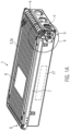
- FIG 1A a perspective view of an endless conveyor device 1 is shown.
- This includes a conveyor unit 2 (see Figure 1B ).
- the conveyor unit 2 contains an endless conveyor 3.
- a plurality of endless conveyors 3 are provided in the form of conveyor belts.
- a single endless conveyor 3, for example in the form of a conveyor belt, is also conceivable.
- the conveyor unit 2 includes a drive roller assembly 4.
- the drive roller assembly 4 may be configured to drive the endless conveyor or conveyors 3.
- the drive roller arrangement 4 can be driven by a drive belt 5 .
- the conveyor unit contains a deflection roller arrangement 6 .
- the deflection roller arrangement 6 can be arranged on a section of the conveyor unit 2 which is opposite to the drive roller arrangement 4 .
- the conveyor unit 2 also includes an intermediate body 7 . This is arranged between the drive roller arrangement 4 and the deflection roller arrangement 6 .
- a conveying run 3a of the endless conveyor 3 can run on a side of the intermediate body 7 facing a conveyed object 8 .
- a return run 3b can run on a side of the intermediate body 7 facing away from the product 8 being conveyed.
- the intermediate body 7 can be arranged between the conveying strand 3a and the return strand 3b.
- the endless conveyor device 1 includes a drive unit 9.
- the drive unit 9 can include the drive belt 5 and a motor (not shown).
- the drive unit 9 and in particular the drive belt 5 and the motor can interact in order to drive the drive roller arrangement 4 .
- the endless conveyor device 1 can have a weighing device 27 .
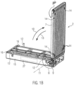
- the endless conveyor device 1 is shown in an unfolded state.
- the conveyor unit 2 has been pivoted in a first direction 10 about an axis of rotation 11 of the drive roller arrangement 4 .
- the endless conveyor device 1 can comprise a first positioning element 12 .
- first positioning elements 12 are provided, of which Figure 1B however, only three are visible.
- the first positioning elements 12 can engage with second positioning elements 14, which can be provided on the conveyor unit 2, in particular on the intermediate body 7.
- the number of second positioning elements 14 can correspond to the number of first positioning elements 12 . Accordingly, instead of the four second positioning elements shown in the exemplary embodiment, only one second positioning element 14 or several, in particular two, three or five, second positioning elements 14 can be provided.
- the first positioning elements 12 can be connected to the drive unit 9 . This can be done by a carrier 15, for example.
- the drive unit 9 can be connected to one or more magnets 16 .
- the connection between the drive unit 9 and the magnets 16 can also be in the form of the carrier 15 .
- the magnets 16 can be configured to pull the conveyor unit 2 and in particular the intermediate body 7 in the second direction 13 .
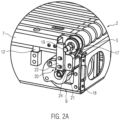
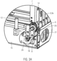
- the drive roller arrangement 4 can have a bearing element 17 .
- the bearing element 17 can have an eccentric 18 .
- the drive roller arrangement 4, in particular the bearing element 17, can also have a shaft extension 19.
- the drive unit 9 can contain a bearing device 20 .
- the bearing device 20 can have a first stop 21 and preferably a second stop 22 .
- the first and the second stop 21, 22 can also be combined in a preferably one-piece component.
- the bearing element 17 can be configured to engage with the bearing device 20 .
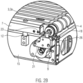
- the eccentric 18 can engage with a first stop surface 23 (see Figure 2B ) that may be provided on the first stopper 21 .
- the engagement between the bearing element 17 and the bearing device 20 may also include an engagement between the shaft extension 19 and a second abutment surface 24 which may be provided on the second abutment 22 .
- the shaft extension 19 can be configured to absorb bearing forces in the conveying direction of the endless conveyor 3, preferably by the engagement of the shaft extension 19 with the bearing device 20, in particular with the second stop surface 24.
- the eccentric 18 can be configured to absorb bearing forces in a direction that essentially perpendicular to the conveying direction of the endless conveyor 3, preferably due to the engagement of the eccentric 18 with the bearing device 20, in particular with the first stop surface 23.
- an end face 26 of the bearing element 17 can engage with an axial stop surface, which can be provided on the bearing device 20, in order to signal that the conveyor unit 2 is arranged in a suitable position in order to place it in the first direction 10 to pan.
Landscapes
- Engineering & Computer Science (AREA)
- Mechanical Engineering (AREA)
- General Engineering & Computer Science (AREA)
- Structure Of Belt Conveyors (AREA)
Claims (6)
- Dispositif de transport en continu (1), comprenant :
une unité de transport (2) avec :au moins un transporteur en continu (3) configuré pour transporter des objets (8), de manière préférée des aliments,un agencement de rouleaux d'entraînement (4) qui peut être entraîné grâce à une courroie d'entraînement (5) et est configuré pour entraîner le transporteur en continu (3) et qui présente un élément formant palier (17),un agencement de rouleaux de renvoi (6) etun corps intermédiaire (7) agencé entre l'agencement de rouleaux d'entraînement (4) et l'agencement de rouleaux de renvoi (6), ainsi qu'entre un compartiment de transport (3a) et un compartiment de retour (3b) du transporteur en continu (3) ;une unité d'entraînement (9) qui comprend la courroie d'entraînement (5), un moteur ainsi qu'un dispositif pour palier (20) configuré pour venir en prise avec l'élément formant palier (17), dans lequel la courroie d'entraînement (5) peut être relâchée grâce à un pivotement de l'unité de transport (2) par rapport à l'unité d'entraînement (9) dans une première direction (10),caractérisé en ce que le pivotement de l'unité de transport (2) s'effectue autour d'un axe de rotation (11) de l'agencement de rouleaux d'entraînement (4), en ce que l'élément formant palier (17) présente un excentrique (18) et en ce que le dispositif pour palier (20) présente une première surface de butée (23) configurée pour venir en prise avec l'excentrique (18). - Dispositif de transport en continu selon la revendication 1, dans lequel l'unité d'entraînement (9) et/ou l'unité de transport (2) est reliée à un aimant (16) qui tire magnétiquement l'unité de transport (2) dans une seconde direction (13) opposée à la première direction (10).
- Dispositif de transport en continu selon l'une quelconque des revendications précédentes, dans lequel le dispositif de transport en continu (1) présente en outre un dispositif de pesage (27) et est configuré pour déterminer une masse des objets (8) transportés.
- Dispositif de transport en continu selon l'une quelconque des revendications précédentes, dans lequel l'unité d'entraînement (9) et/ou le dispositif de pesage (27) présente un premier élément de positionnement (12) configuré pour venir en prise avec un second élément de positionnement (14) prévu au niveau du corps intermédiaire (7).
- Procédé permettant de retirer une unité de transport (2) d'un dispositif de transport en continu (1), dans lequel l'unité de transport (2) comprend au moins un transporteur en continu (3), un agencement de rouleaux d'entraînement (4), un agencement de rouleaux de renvoi (6) et un corps intermédiaire (7) agencé entre l'agencement de rouleaux d'entraînement (4) et l'agencement de rouleaux de renvoi (6), dans lequel le procédé comprend l'étape consistant à :faire pivoter l'unité de transport (2) par rapport à une unité d'entraînement (9), ce qui relâche une courroie d'entraînement (5) en prise avec l'agencement de rouleaux d'entraînement (4),caractérisé en ce que le pivotement de l'unité de transport (2) s'effectue autour d'un axe de rotation (11) de l'agencement de rouleaux d'entraînement (4), et en ce que le procédé comprend l'étape consistant à :déplacer l'unité de transport (2) dans une direction parallèle à l'axe de rotation (11), ce qui retire la courroie d'entraînement (5) de l'agencement de rouleaux d'entraînement (4), dans lequelle relâchement de la courroie d'entraînement (5) pendant le pivotement est provoqué par un excentrique (18) agencé de manière préférée au niveau de l'agencement de rouleaux d'entraînement (4).
- Procédé selon la revendication 5, dans lequel le pivotement de l'unité de transport (2) comprend une étape consistant à surmonter une force de retenue générée de manière préférée par des aimants (16).
Applications Claiming Priority (1)
| Application Number | Priority Date | Filing Date | Title |
|---|---|---|---|
| DE102018222579.6A DE102018222579B4 (de) | 2018-12-20 | 2018-12-20 | Endlosfördervorrichtung mit entnehmbarer Fördereinheit und Verfahren |
Publications (2)
| Publication Number | Publication Date |
|---|---|
| EP3670395A1 EP3670395A1 (fr) | 2020-06-24 |
| EP3670395B1 true EP3670395B1 (fr) | 2023-09-06 |
Family
ID=68916307
Family Applications (1)
| Application Number | Title | Priority Date | Filing Date |
|---|---|---|---|
| EP19215885.5A Active EP3670395B1 (fr) | 2018-12-20 | 2019-12-13 | Dispositif de transporteur continu pourvu d'unité de transport pouvant être retiré et procédé |
Country Status (3)
| Country | Link |
|---|---|
| US (1) | US11014752B2 (fr) |
| EP (1) | EP3670395B1 (fr) |
| DE (1) | DE102018222579B4 (fr) |
Families Citing this family (3)
| Publication number | Priority date | Publication date | Assignee | Title |
|---|---|---|---|---|
| GB201806932D0 (en) * | 2018-04-27 | 2018-06-13 | Litestructures Projects Uk Ltd | Conveyor |
| US10988319B2 (en) * | 2019-08-01 | 2021-04-27 | Intelligrated Headquarters, Llc | Multi-belt conveyor system with removable cartridges |
| DE202021104227U1 (de) * | 2021-08-06 | 2021-08-12 | Wipotec Gmbh | Fördervorrichtung mit Transportkassette |
Family Cites Families (8)
| Publication number | Priority date | Publication date | Assignee | Title |
|---|---|---|---|---|
| JPH066099Y2 (ja) * | 1986-08-08 | 1994-02-16 | 株式会社石田衡器製作所 | 商品の重量判定装置 |
| KR100582758B1 (ko) | 2004-12-02 | 2006-05-23 | (주)제이브이엠 | 약제 자동 포장기용 약제다발 이송장치 |
| US8469182B2 (en) | 2011-09-09 | 2013-06-25 | Felice S.R.L. | Quick-remove conveyor belt, in particular for transporting food products to a packaging station |
| DE102013206510A1 (de) * | 2012-12-03 | 2014-06-05 | Textor Maschinenbau GmbH | Hochleistungsaufschnittschneidemaschine mit zumindest einer entnehmbaren Bandkassette |
| ES2955496T3 (es) * | 2014-01-24 | 2023-12-01 | Laitram Llc | Limitador de posición de encaje a presión para una cinta transportadora |
| CN104249915A (zh) * | 2014-09-26 | 2014-12-31 | 成都三可实业有限公司 | 一种用于输糖装置的齿链张紧组件 |
| DE102016108135B4 (de) * | 2016-05-02 | 2019-05-23 | Wipotec Wiege- Und Positioniersysteme Gmbh | Eingreifschutz für Riemenantrieb |
| DE102018204043A1 (de) | 2018-03-16 | 2019-09-19 | Multivac Sepp Haggenmüller Se & Co. Kg | Transportvorrichtung mit Verriegelungsmechanismus |
-
2018
- 2018-12-20 DE DE102018222579.6A patent/DE102018222579B4/de active Active
-
2019
- 2019-12-13 EP EP19215885.5A patent/EP3670395B1/fr active Active
- 2019-12-19 US US16/720,415 patent/US11014752B2/en active Active
Also Published As
| Publication number | Publication date |
|---|---|
| DE102018222579A1 (de) | 2020-06-25 |
| DE102018222579B4 (de) | 2020-07-02 |
| US11014752B2 (en) | 2021-05-25 |
| EP3670395A1 (fr) | 2020-06-24 |
| US20200198896A1 (en) | 2020-06-25 |
Similar Documents
| Publication | Publication Date | Title |
|---|---|---|
| DE60118948T2 (de) | Überführung von gegenständen zwischen entgegengesetzt angetriebenen förderern | |
| EP2783819B1 (fr) | Cassette amovible de bande de convoyeur et trancheur haute puissance doté d'au moins une cassette de bande amovible | |
| EP3670395B1 (fr) | Dispositif de transporteur continu pourvu d'unité de transport pouvant être retiré et procédé | |
| DE69720125T2 (de) | Transporteinheit für Produkte | |
| DE102006047280A1 (de) | Vorrichtung zum Überführen und Platzieren von Artikeln | |
| CH673837A5 (fr) | ||
| DE60113580T2 (de) | Schneidemaschine für eine Vielzahl von Küchen- und/oder Toiletten-Papierrollen | |
| EP0564901B1 (fr) | Dispositif d'avance pour tÔle | |
| DE102008008009A1 (de) | Fördereinrichtung zum vertikalen Transport von Stückgut | |
| EP3415669B1 (fr) | Dispositif de transport pour un bobineur de non-tissé | |
| EP3281529B1 (fr) | Dispositif et procédé d'alignement de saucisses | |
| EP2583362B1 (fr) | Dispositif destiné à mettre en place des passe-câbles sur un câble | |
| DE19510649A1 (de) | Transportvorrichtung | |
| DE10212024A1 (de) | Vorrichtung und Verfahren zum Vereinzeln von flächigen Stückgütern | |
| DE69901434T2 (de) | Kurverförderer | |
| DE102010016020A1 (de) | Fördereinheit für ein Transportsystem für Artikel | |
| DE69605720T2 (de) | Vorrichtung zur automatischen Handhabung von Produkten oder Paketen | |
| DE19638307B4 (de) | Verfahren zum Schneiden von kontinuierlich geförderten, flächigen Produkten aus Papier oder ähnlichen Materialien | |
| DE69423763T2 (de) | Verfahren und vorrichtung zum enthäuten von wurst | |
| DE102018113611A1 (de) | Fördervorrichtung für Lebensmittelprodukte mit flexiblem Träger | |
| DE102006045020B4 (de) | Vibrationsfördereraufbau | |
| EP1829805B1 (fr) | Dispositif destiné à la séparation de pièces découpées de cartonnages | |
| DE19950401A1 (de) | Vorrichtung zum Drehen von auf einer Federwindemaschine hergestellten Federn | |
| DE2919488A1 (de) | Verfahren und vorrichtung zum vereinzeln von im wesentlichen rechteckigen oder quadratischen gefaessen, insbesondere in gefaessbehandlungsmaschinen | |
| EP1915306A1 (fr) | Systeme de transport |
Legal Events
| Date | Code | Title | Description |
|---|---|---|---|
| PUAI | Public reference made under article 153(3) epc to a published international application that has entered the european phase |
Free format text: ORIGINAL CODE: 0009012 |
|
| STAA | Information on the status of an ep patent application or granted ep patent |
Free format text: STATUS: THE APPLICATION HAS BEEN PUBLISHED |
|
| AK | Designated contracting states |
Kind code of ref document: A1 Designated state(s): AL AT BE BG CH CY CZ DE DK EE ES FI FR GB GR HR HU IE IS IT LI LT LU LV MC MK MT NL NO PL PT RO RS SE SI SK SM TR |
|
| AX | Request for extension of the european patent |
Extension state: BA ME |
|
| RIN1 | Information on inventor provided before grant (corrected) |
Inventor name: TREISE, ARTHUR |
|
| STAA | Information on the status of an ep patent application or granted ep patent |
Free format text: STATUS: REQUEST FOR EXAMINATION WAS MADE |
|
| 17P | Request for examination filed |
Effective date: 20201214 |
|
| RBV | Designated contracting states (corrected) |
Designated state(s): AL AT BE BG CH CY CZ DE DK EE ES FI FR GB GR HR HU IE IS IT LI LT LU LV MC MK MT NL NO PL PT RO RS SE SI SK SM TR |
|
| RIC1 | Information provided on ipc code assigned before grant |
Ipc: G01G 19/03 20060101ALN20221219BHEP Ipc: F16H 7/10 20060101ALI20221219BHEP Ipc: B65G 23/24 20060101ALI20221219BHEP Ipc: B65G 21/10 20060101AFI20221219BHEP |
|
| GRAP | Despatch of communication of intention to grant a patent |
Free format text: ORIGINAL CODE: EPIDOSNIGR1 |
|
| STAA | Information on the status of an ep patent application or granted ep patent |
Free format text: STATUS: GRANT OF PATENT IS INTENDED |
|
| INTG | Intention to grant announced |
Effective date: 20230130 |
|
| GRAJ | Information related to disapproval of communication of intention to grant by the applicant or resumption of examination proceedings by the epo deleted |
Free format text: ORIGINAL CODE: EPIDOSDIGR1 |
|
| STAA | Information on the status of an ep patent application or granted ep patent |
Free format text: STATUS: REQUEST FOR EXAMINATION WAS MADE |
|
| GRAP | Despatch of communication of intention to grant a patent |
Free format text: ORIGINAL CODE: EPIDOSNIGR1 |
|
| STAA | Information on the status of an ep patent application or granted ep patent |
Free format text: STATUS: GRANT OF PATENT IS INTENDED |
|
| INTC | Intention to grant announced (deleted) | ||
| RIC1 | Information provided on ipc code assigned before grant |
Ipc: G01G 19/03 20060101ALN20230403BHEP Ipc: F16H 7/10 20060101ALI20230403BHEP Ipc: B65G 23/24 20060101ALI20230403BHEP Ipc: B65G 21/10 20060101AFI20230403BHEP |
|
| INTG | Intention to grant announced |
Effective date: 20230420 |
|
| P01 | Opt-out of the competence of the unified patent court (upc) registered |
Effective date: 20230404 |
|
| GRAS | Grant fee paid |
Free format text: ORIGINAL CODE: EPIDOSNIGR3 |
|
| GRAA | (expected) grant |
Free format text: ORIGINAL CODE: 0009210 |
|
| STAA | Information on the status of an ep patent application or granted ep patent |
Free format text: STATUS: THE PATENT HAS BEEN GRANTED |
|
| AK | Designated contracting states |
Kind code of ref document: B1 Designated state(s): AL AT BE BG CH CY CZ DE DK EE ES FI FR GB GR HR HU IE IS IT LI LT LU LV MC MK MT NL NO PL PT RO RS SE SI SK SM TR |
|
| REG | Reference to a national code |
Ref country code: GB Ref legal event code: FG4D Free format text: NOT ENGLISH |
|
| REG | Reference to a national code |
Ref country code: CH Ref legal event code: EP |
|
| REG | Reference to a national code |
Ref country code: DE Ref legal event code: R096 Ref document number: 502019009241 Country of ref document: DE |
|
| REG | Reference to a national code |
Ref country code: IE Ref legal event code: FG4D Free format text: LANGUAGE OF EP DOCUMENT: GERMAN |
|
| REG | Reference to a national code |
Ref country code: LT Ref legal event code: MG9D |
|
| REG | Reference to a national code |
Ref country code: NL Ref legal event code: MP Effective date: 20230906 |
|
| PG25 | Lapsed in a contracting state [announced via postgrant information from national office to epo] |
Ref country code: GR Free format text: LAPSE BECAUSE OF FAILURE TO SUBMIT A TRANSLATION OF THE DESCRIPTION OR TO PAY THE FEE WITHIN THE PRESCRIBED TIME-LIMIT Effective date: 20231207 |
|
| PG25 | Lapsed in a contracting state [announced via postgrant information from national office to epo] |
Ref country code: SE Free format text: LAPSE BECAUSE OF FAILURE TO SUBMIT A TRANSLATION OF THE DESCRIPTION OR TO PAY THE FEE WITHIN THE PRESCRIBED TIME-LIMIT Effective date: 20230906 Ref country code: RS Free format text: LAPSE BECAUSE OF FAILURE TO SUBMIT A TRANSLATION OF THE DESCRIPTION OR TO PAY THE FEE WITHIN THE PRESCRIBED TIME-LIMIT Effective date: 20230906 Ref country code: NO Free format text: LAPSE BECAUSE OF FAILURE TO SUBMIT A TRANSLATION OF THE DESCRIPTION OR TO PAY THE FEE WITHIN THE PRESCRIBED TIME-LIMIT Effective date: 20231206 Ref country code: LV Free format text: LAPSE BECAUSE OF FAILURE TO SUBMIT A TRANSLATION OF THE DESCRIPTION OR TO PAY THE FEE WITHIN THE PRESCRIBED TIME-LIMIT Effective date: 20230906 Ref country code: LT Free format text: LAPSE BECAUSE OF FAILURE TO SUBMIT A TRANSLATION OF THE DESCRIPTION OR TO PAY THE FEE WITHIN THE PRESCRIBED TIME-LIMIT Effective date: 20230906 Ref country code: HR Free format text: LAPSE BECAUSE OF FAILURE TO SUBMIT A TRANSLATION OF THE DESCRIPTION OR TO PAY THE FEE WITHIN THE PRESCRIBED TIME-LIMIT Effective date: 20230906 Ref country code: GR Free format text: LAPSE BECAUSE OF FAILURE TO SUBMIT A TRANSLATION OF THE DESCRIPTION OR TO PAY THE FEE WITHIN THE PRESCRIBED TIME-LIMIT Effective date: 20231207 Ref country code: FI Free format text: LAPSE BECAUSE OF FAILURE TO SUBMIT A TRANSLATION OF THE DESCRIPTION OR TO PAY THE FEE WITHIN THE PRESCRIBED TIME-LIMIT Effective date: 20230906 |
|
| PG25 | Lapsed in a contracting state [announced via postgrant information from national office to epo] |
Ref country code: NL Free format text: LAPSE BECAUSE OF FAILURE TO SUBMIT A TRANSLATION OF THE DESCRIPTION OR TO PAY THE FEE WITHIN THE PRESCRIBED TIME-LIMIT Effective date: 20230906 |
|
| PG25 | Lapsed in a contracting state [announced via postgrant information from national office to epo] |
Ref country code: IS Free format text: LAPSE BECAUSE OF FAILURE TO SUBMIT A TRANSLATION OF THE DESCRIPTION OR TO PAY THE FEE WITHIN THE PRESCRIBED TIME-LIMIT Effective date: 20240106 |
|
| PG25 | Lapsed in a contracting state [announced via postgrant information from national office to epo] |
Ref country code: ES Free format text: LAPSE BECAUSE OF FAILURE TO SUBMIT A TRANSLATION OF THE DESCRIPTION OR TO PAY THE FEE WITHIN THE PRESCRIBED TIME-LIMIT Effective date: 20230906 |
|
| PG25 | Lapsed in a contracting state [announced via postgrant information from national office to epo] |
Ref country code: SM Free format text: LAPSE BECAUSE OF FAILURE TO SUBMIT A TRANSLATION OF THE DESCRIPTION OR TO PAY THE FEE WITHIN THE PRESCRIBED TIME-LIMIT Effective date: 20230906 Ref country code: RO Free format text: LAPSE BECAUSE OF FAILURE TO SUBMIT A TRANSLATION OF THE DESCRIPTION OR TO PAY THE FEE WITHIN THE PRESCRIBED TIME-LIMIT Effective date: 20230906 Ref country code: IS Free format text: LAPSE BECAUSE OF FAILURE TO SUBMIT A TRANSLATION OF THE DESCRIPTION OR TO PAY THE FEE WITHIN THE PRESCRIBED TIME-LIMIT Effective date: 20240106 Ref country code: ES Free format text: LAPSE BECAUSE OF FAILURE TO SUBMIT A TRANSLATION OF THE DESCRIPTION OR TO PAY THE FEE WITHIN THE PRESCRIBED TIME-LIMIT Effective date: 20230906 Ref country code: EE Free format text: LAPSE BECAUSE OF FAILURE TO SUBMIT A TRANSLATION OF THE DESCRIPTION OR TO PAY THE FEE WITHIN THE PRESCRIBED TIME-LIMIT Effective date: 20230906 Ref country code: CZ Free format text: LAPSE BECAUSE OF FAILURE TO SUBMIT A TRANSLATION OF THE DESCRIPTION OR TO PAY THE FEE WITHIN THE PRESCRIBED TIME-LIMIT Effective date: 20230906 Ref country code: PT Free format text: LAPSE BECAUSE OF FAILURE TO SUBMIT A TRANSLATION OF THE DESCRIPTION OR TO PAY THE FEE WITHIN THE PRESCRIBED TIME-LIMIT Effective date: 20240108 Ref country code: SK Free format text: LAPSE BECAUSE OF FAILURE TO SUBMIT A TRANSLATION OF THE DESCRIPTION OR TO PAY THE FEE WITHIN THE PRESCRIBED TIME-LIMIT Effective date: 20230906 |
|
| PG25 | Lapsed in a contracting state [announced via postgrant information from national office to epo] |
Ref country code: PL Free format text: LAPSE BECAUSE OF FAILURE TO SUBMIT A TRANSLATION OF THE DESCRIPTION OR TO PAY THE FEE WITHIN THE PRESCRIBED TIME-LIMIT Effective date: 20230906 Ref country code: IT Free format text: LAPSE BECAUSE OF FAILURE TO SUBMIT A TRANSLATION OF THE DESCRIPTION OR TO PAY THE FEE WITHIN THE PRESCRIBED TIME-LIMIT Effective date: 20230906 |
|
| REG | Reference to a national code |
Ref country code: DE Ref legal event code: R097 Ref document number: 502019009241 Country of ref document: DE |
|
| PG25 | Lapsed in a contracting state [announced via postgrant information from national office to epo] |
Ref country code: DK Free format text: LAPSE BECAUSE OF FAILURE TO SUBMIT A TRANSLATION OF THE DESCRIPTION OR TO PAY THE FEE WITHIN THE PRESCRIBED TIME-LIMIT Effective date: 20230906 |
|
| PLBE | No opposition filed within time limit |
Free format text: ORIGINAL CODE: 0009261 |
|
| STAA | Information on the status of an ep patent application or granted ep patent |
Free format text: STATUS: NO OPPOSITION FILED WITHIN TIME LIMIT |
|
| PG25 | Lapsed in a contracting state [announced via postgrant information from national office to epo] |
Ref country code: DK Free format text: LAPSE BECAUSE OF FAILURE TO SUBMIT A TRANSLATION OF THE DESCRIPTION OR TO PAY THE FEE WITHIN THE PRESCRIBED TIME-LIMIT Effective date: 20230906 Ref country code: SI Free format text: LAPSE BECAUSE OF FAILURE TO SUBMIT A TRANSLATION OF THE DESCRIPTION OR TO PAY THE FEE WITHIN THE PRESCRIBED TIME-LIMIT Effective date: 20230906 |
|
| REG | Reference to a national code |
Ref country code: CH Ref legal event code: PL |
|
| 26N | No opposition filed |
Effective date: 20240607 |
|
| PG25 | Lapsed in a contracting state [announced via postgrant information from national office to epo] |
Ref country code: LU Free format text: LAPSE BECAUSE OF NON-PAYMENT OF DUE FEES Effective date: 20231213 |
|
| PG25 | Lapsed in a contracting state [announced via postgrant information from national office to epo] |
Ref country code: MC Free format text: LAPSE BECAUSE OF FAILURE TO SUBMIT A TRANSLATION OF THE DESCRIPTION OR TO PAY THE FEE WITHIN THE PRESCRIBED TIME-LIMIT Effective date: 20230906 |
|
| GBPC | Gb: european patent ceased through non-payment of renewal fee |
Effective date: 20231213 |
|
| REG | Reference to a national code |
Ref country code: BE Ref legal event code: MM Effective date: 20231231 |
|
| PG25 | Lapsed in a contracting state [announced via postgrant information from national office to epo] |
Ref country code: MC Free format text: LAPSE BECAUSE OF FAILURE TO SUBMIT A TRANSLATION OF THE DESCRIPTION OR TO PAY THE FEE WITHIN THE PRESCRIBED TIME-LIMIT Effective date: 20230906 Ref country code: LU Free format text: LAPSE BECAUSE OF NON-PAYMENT OF DUE FEES Effective date: 20231213 |
|
| REG | Reference to a national code |
Ref country code: IE Ref legal event code: MM4A |
|
| PG25 | Lapsed in a contracting state [announced via postgrant information from national office to epo] |
Ref country code: IE Free format text: LAPSE BECAUSE OF NON-PAYMENT OF DUE FEES Effective date: 20231213 |
|
| PG25 | Lapsed in a contracting state [announced via postgrant information from national office to epo] |
Ref country code: GB Free format text: LAPSE BECAUSE OF NON-PAYMENT OF DUE FEES Effective date: 20231213 |
|
| PG25 | Lapsed in a contracting state [announced via postgrant information from national office to epo] |
Ref country code: BE Free format text: LAPSE BECAUSE OF NON-PAYMENT OF DUE FEES Effective date: 20231231 |
|
| PG25 | Lapsed in a contracting state [announced via postgrant information from national office to epo] |
Ref country code: FR Free format text: LAPSE BECAUSE OF NON-PAYMENT OF DUE FEES Effective date: 20231231 |
|
| PG25 | Lapsed in a contracting state [announced via postgrant information from national office to epo] |
Ref country code: CH Free format text: LAPSE BECAUSE OF NON-PAYMENT OF DUE FEES Effective date: 20231231 |
|
| PG25 | Lapsed in a contracting state [announced via postgrant information from national office to epo] |
Ref country code: IE Free format text: LAPSE BECAUSE OF NON-PAYMENT OF DUE FEES Effective date: 20231213 Ref country code: GB Free format text: LAPSE BECAUSE OF NON-PAYMENT OF DUE FEES Effective date: 20231213 Ref country code: FR Free format text: LAPSE BECAUSE OF NON-PAYMENT OF DUE FEES Effective date: 20231231 Ref country code: CH Free format text: LAPSE BECAUSE OF NON-PAYMENT OF DUE FEES Effective date: 20231231 Ref country code: BE Free format text: LAPSE BECAUSE OF NON-PAYMENT OF DUE FEES Effective date: 20231231 |
|
| PG25 | Lapsed in a contracting state [announced via postgrant information from national office to epo] |
Ref country code: BG Free format text: LAPSE BECAUSE OF FAILURE TO SUBMIT A TRANSLATION OF THE DESCRIPTION OR TO PAY THE FEE WITHIN THE PRESCRIBED TIME-LIMIT Effective date: 20230906 |
|
| PG25 | Lapsed in a contracting state [announced via postgrant information from national office to epo] |
Ref country code: BG Free format text: LAPSE BECAUSE OF FAILURE TO SUBMIT A TRANSLATION OF THE DESCRIPTION OR TO PAY THE FEE WITHIN THE PRESCRIBED TIME-LIMIT Effective date: 20230906 |
|
| PG25 | Lapsed in a contracting state [announced via postgrant information from national office to epo] |
Ref country code: CY Free format text: LAPSE BECAUSE OF FAILURE TO SUBMIT A TRANSLATION OF THE DESCRIPTION OR TO PAY THE FEE WITHIN THE PRESCRIBED TIME-LIMIT; INVALID AB INITIO Effective date: 20191213 |
|
| PG25 | Lapsed in a contracting state [announced via postgrant information from national office to epo] |
Ref country code: HU Free format text: LAPSE BECAUSE OF FAILURE TO SUBMIT A TRANSLATION OF THE DESCRIPTION OR TO PAY THE FEE WITHIN THE PRESCRIBED TIME-LIMIT; INVALID AB INITIO Effective date: 20191213 |
|
| PG25 | Lapsed in a contracting state [announced via postgrant information from national office to epo] |
Ref country code: TR Free format text: LAPSE BECAUSE OF FAILURE TO SUBMIT A TRANSLATION OF THE DESCRIPTION OR TO PAY THE FEE WITHIN THE PRESCRIBED TIME-LIMIT Effective date: 20230906 |
|
| REG | Reference to a national code |
Ref country code: AT Ref legal event code: MM01 Ref document number: 1608299 Country of ref document: AT Kind code of ref document: T Effective date: 20241213 |
|
| PGFP | Annual fee paid to national office [announced via postgrant information from national office to epo] |
Ref country code: DE Payment date: 20251222 Year of fee payment: 7 |
|
| PG25 | Lapsed in a contracting state [announced via postgrant information from national office to epo] |
Ref country code: AT Free format text: LAPSE BECAUSE OF NON-PAYMENT OF DUE FEES Effective date: 20241213 |
|
| PGFP | Annual fee paid to national office [announced via postgrant information from national office to epo] |
Ref country code: AT Payment date: 20260410 Year of fee payment: 5 |