EP3353859B1 - Dispositif de connexion pour conducteur - Google Patents
Dispositif de connexion pour conducteur Download PDFInfo
- Publication number
- EP3353859B1 EP3353859B1 EP16766546.2A EP16766546A EP3353859B1 EP 3353859 B1 EP3353859 B1 EP 3353859B1 EP 16766546 A EP16766546 A EP 16766546A EP 3353859 B1 EP3353859 B1 EP 3353859B1
- Authority
- EP
- European Patent Office
- Prior art keywords
- spring
- clamping
- connection device
- busbar
- conductor
- Prior art date
- Legal status (The legal status is an assumption and is not a legal conclusion. Google has not performed a legal analysis and makes no representation as to the accuracy of the status listed.)
- Active
Links
Images


Classifications
-
- H—ELECTRICITY
- H01—ELECTRIC ELEMENTS
- H01R—ELECTRICALLY-CONDUCTIVE CONNECTIONS; STRUCTURAL ASSOCIATIONS OF A PLURALITY OF MUTUALLY-INSULATED ELECTRICAL CONNECTING ELEMENTS; COUPLING DEVICES; CURRENT COLLECTORS
- H01R11/00—Individual connecting elements providing two or more spaced connecting locations for conductive members which are, or may be, thereby interconnected, e.g. end pieces for wires or cables supported by the wire or cable and having means for facilitating electrical connection to some other wire, terminal, or conductive member, blocks of binding posts
- H01R11/03—Individual connecting elements providing two or more spaced connecting locations for conductive members which are, or may be, thereby interconnected, e.g. end pieces for wires or cables supported by the wire or cable and having means for facilitating electrical connection to some other wire, terminal, or conductive member, blocks of binding posts characterised by the relationship between the connecting locations
- H01R11/09—Individual connecting elements providing two or more spaced connecting locations for conductive members which are, or may be, thereby interconnected, e.g. end pieces for wires or cables supported by the wire or cable and having means for facilitating electrical connection to some other wire, terminal, or conductive member, blocks of binding posts characterised by the relationship between the connecting locations the connecting locations being identical
-
- H—ELECTRICITY
- H01—ELECTRIC ELEMENTS
- H01R—ELECTRICALLY-CONDUCTIVE CONNECTIONS; STRUCTURAL ASSOCIATIONS OF A PLURALITY OF MUTUALLY-INSULATED ELECTRICAL CONNECTING ELEMENTS; COUPLING DEVICES; CURRENT COLLECTORS
- H01R25/00—Coupling parts adapted for simultaneous co-operation with two or more identical counterparts, e.g. for distributing energy to two or more circuits
- H01R25/16—Rails or bus-bars provided with a plurality of discrete connecting locations for counterparts
- H01R25/161—Details
- H01R25/162—Electrical connections between or with rails or bus-bars
-
- H—ELECTRICITY
- H01—ELECTRIC ELEMENTS
- H01R—ELECTRICALLY-CONDUCTIVE CONNECTIONS; STRUCTURAL ASSOCIATIONS OF A PLURALITY OF MUTUALLY-INSULATED ELECTRICAL CONNECTING ELEMENTS; COUPLING DEVICES; CURRENT COLLECTORS
- H01R4/00—Electrically-conductive connections between two or more conductive members in direct contact, i.e. touching one another; Means for effecting or maintaining such contact; Electrically-conductive connections having two or more spaced connecting locations for conductors and using contact members penetrating insulation
- H01R4/28—Clamped connections, spring connections
- H01R4/48—Clamped connections, spring connections utilising a spring, clip, or other resilient member
- H01R4/4809—Clamped connections, spring connections utilising a spring, clip, or other resilient member using a leaf spring to bias the conductor toward the busbar
- H01R4/48185—Clamped connections, spring connections utilising a spring, clip, or other resilient member using a leaf spring to bias the conductor toward the busbar adapted for axial insertion of a wire end
- H01R4/4819—Clamped connections, spring connections utilising a spring, clip, or other resilient member using a leaf spring to bias the conductor toward the busbar adapted for axial insertion of a wire end the spring shape allowing insertion of the conductor end when the spring is unbiased
- H01R4/4821—Single-blade spring
-
- H—ELECTRICITY
- H01—ELECTRIC ELEMENTS
- H01R—ELECTRICALLY-CONDUCTIVE CONNECTIONS; STRUCTURAL ASSOCIATIONS OF A PLURALITY OF MUTUALLY-INSULATED ELECTRICAL CONNECTING ELEMENTS; COUPLING DEVICES; CURRENT COLLECTORS
- H01R4/00—Electrically-conductive connections between two or more conductive members in direct contact, i.e. touching one another; Means for effecting or maintaining such contact; Electrically-conductive connections having two or more spaced connecting locations for conductors and using contact members penetrating insulation
- H01R4/28—Clamped connections, spring connections
- H01R4/48—Clamped connections, spring connections utilising a spring, clip, or other resilient member
- H01R4/4809—Clamped connections, spring connections utilising a spring, clip, or other resilient member using a leaf spring to bias the conductor toward the busbar
- H01R4/4846—Busbar details
- H01R4/485—Single busbar common to multiple springs
-
- H—ELECTRICITY
- H01—ELECTRIC ELEMENTS
- H01R—ELECTRICALLY-CONDUCTIVE CONNECTIONS; STRUCTURAL ASSOCIATIONS OF A PLURALITY OF MUTUALLY-INSULATED ELECTRICAL CONNECTING ELEMENTS; COUPLING DEVICES; CURRENT COLLECTORS
- H01R4/00—Electrically-conductive connections between two or more conductive members in direct contact, i.e. touching one another; Means for effecting or maintaining such contact; Electrically-conductive connections having two or more spaced connecting locations for conductors and using contact members penetrating insulation
- H01R4/28—Clamped connections, spring connections
- H01R4/48—Clamped connections, spring connections utilising a spring, clip, or other resilient member
- H01R4/4809—Clamped connections, spring connections utilising a spring, clip, or other resilient member using a leaf spring to bias the conductor toward the busbar
- H01R4/4828—Spring-activating arrangements mounted on or integrally formed with the spring housing
- H01R4/4833—Sliding arrangements, e.g. sliding button
-
- H—ELECTRICITY
- H01—ELECTRIC ELEMENTS
- H01R—ELECTRICALLY-CONDUCTIVE CONNECTIONS; STRUCTURAL ASSOCIATIONS OF A PLURALITY OF MUTUALLY-INSULATED ELECTRICAL CONNECTING ELEMENTS; COUPLING DEVICES; CURRENT COLLECTORS
- H01R9/00—Structural associations of a plurality of mutually-insulated electrical connecting elements, e.g. terminal strips or terminal blocks; Terminals or binding posts mounted upon a base or in a case; Bases therefor
- H01R9/22—Bases, e.g. strip, block, panel
- H01R9/24—Terminal blocks
- H01R9/2408—Modular blocks
Definitions
- the invention relates to a connection device for conductors with a busbar according to the preamble of claim 1.
- connection devices are known, for example from WO2010/079130A1 and the WO2011/099863A1 .
- the state of the art also includes the DE 10 2008 024 366 A1 and the DE 10 2008 024 266 A1 called.
- DE102011115637 A1 discloses a connection device according to the preamble of claim 1.
- the plurality of spring supports made of non-conductive material can be attached to a corresponding receiving element made of non-conductive material.
- This embodiment makes it possible in a simple manner to use the conductor connection in the different manner described in claim 1.
- one or more mounting means for mounting the spring carrier made of non-conductive material, in particular plastic, on a corresponding Receiving element made of non-conductive material, in particular plastic This design makes it particularly easy to use the single conductor connection in a variety of ways.
- the receiving element for the spring supports is another of the spring supports. This is because double spring supports and thus also double conductor connections can be formed in a simple manner.
- the spring supports, the clamping cages and the clamping springs are pre-assembled on a busbar. This can then be inserted into a housing. The busbar can then be locked onto the housing.
- the individual spring supports it is also conceivable to fix the individual spring supports to the housing (terminal block housing or connector housing) if individual conductor connections are provided.
- the mounting means on the respective spring supports is/are one or more form-locking means.
- one or more corresponding form-locking means are provided on the receiving element, in particular on the further spring support or on or in the housing.
- the corresponding form-locking means are designed as pins and holes that can be clamped together.
- the clamping cage has a U-shape in plan view with a clamping cage rear wall and two clamping cage side walls extending perpendicularly thereto and preferably a base wall extending perpendicularly to the clamping cage rear wall and the clamping cage side walls or a base base for fastening the respective clamping cage to a busbar and if the spring supports each have a U-shape in plan view with a base wall and two side walls extending perpendicularly thereto.
- the spring supports each have a U-shape in plan view and the clamping cages also have a U-shape in plan view
- the spring supports and the clamping cages can each be combined to form a body with a rectangular contour in plan view, so that on the one hand the clamping spring is well protected and on the other hand a conductor guide to the clamping point is implemented in a simple manner.
- the one or more spring supports have one or more spring holding contour(s) extending perpendicular to the base wall, so that a clamping spring can be placed on each of them, which is V-shaped and has a support leg and a clamping leg arranged at an acute angle to this at an angle (10° ⁇ ⁇ ⁇ 90°), wherein the support leg and the clamping leg are connected to one another via a spring back and wherein the spring back of the respective clamping spring overlaps the spring holding contour of the spring support.
- two of the individual conductor connections are combined to form several higher-level double conductor connections with two spring supports, two of the clamping springs and two of the clamping cages, which are then assembled on the corresponding mounting means.
- These two individual conductor connections of the double conductor connection can have clamping points located at the same location in the main extension direction of the busbar or clamping points offset in the main extension direction of the busbar. This flexibility is only possible because, unlike in the prior art, each individual conductor connection of the respective double conductor connection has an individual spring support.
- an intermediate piece which can be attached to the spring carrier in order to increase its width.
- This intermediate piece preferably has mounting means on one side of a base wall or both sides, which are designed to correspond to the mounting means of the spring carrier in order to mount the spring carrier or two of the spring carriers on the intermediate piece. In this way, a wide variety of connection grid widths can be realized in a simple manner.
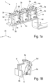
- Fig. 1 shows a first embodiment of a connection device 1 for conductors.
- This connection device 1 is designed as a multiple conductor connection and allows (purely as an example) the connection of six conductor ends (not shown here).
- connection device has six individual conductor connections 2a, 2b; 3a, 3b, 4a, 4b, which are Fig. 1 According to an advantageous option, they are combined here into three higher-level double-conductor connections, each of which serves to connect two of the conductors.
- the individual conductor connections 2a, 2b; 3a, 3b, 4a, 4b are each designed as direct plug connections (called push-in).
- Each of the (here, six as an example) individual conductor connections 2a, 2b; 3a, 3b, 4a, 4b has a metallic contact element, in particular a clamping cage 5 or 5', a spring carrier 6 or 6' made of non-conductive material, in particular a non-conductive plastic, and a clamping spring 7.
- a self-contained, functional individual conductor connection is created. which can preferably be combined with other individual conductor connections to form higher-level arrangements.
- Each clamping cage 5 or 5' has a U-shape in plan view with a clamping cage rear wall 5a or 5a' and two clamping cage side walls 5b, 5c or 5b', 5c' extending perpendicularly thereto. It also has a base wall or a base base 5d or 5d' extending perpendicularly to the rear wall 5a or 5a' and the clamping cage side walls 5b, c.
- This clamping cage base wall 5d or 5d' is used to attach the respective clamping cage 5 or 5' to a busbar 8.
- the base wall 5d or 5d' is preferably soldered or welded to the busbar 8.
- the clamping cages 5 or 5' are arranged one behind the other in a longitudinal direction Y of the busbar 8. Since the clamping cages 5 are not formed in one piece with the busbar 8 but are attached to it, the clamping cages can be arranged close together in the longitudinal direction Y. In particular, their distance in the Y direction can be much smaller than the longitudinal extent of the clamping cages 5.
- a conductive contact element as a clamping cage 5 in the sense of this application can also have only one or two conductive legs, although preferably more than two walls/legs are provided on it.
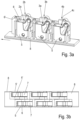
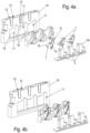
- the spring carriers 6 or 6' (see also Fig. 4a ) have a U-shape in plan view with a base wall 6a or 6a' and two side walls 6b, 6c or 6b', 6c' extending perpendicularly thereto. At least one spring holding contour 6d or 6d' extends perpendicular to the base wall 6a.
- the spring supports 6' also have mounting means - in particular form-locking means - on their rear walls 6a, 6a', which are designed to interact with corresponding mounting means - in particular also form-locking means - on a receiving element.
- This receiving element - for example a further spring support 6 or 6' or a housing, in particular of a plug or a terminal - is designed to attach and mount the respective spring support 6, 6' or several of the spring supports 6, 6' on a receiving element and can be designed in various ways. This is explained in more detail below using various options.
- the clamping spring 7 (see also Fig. 4a ) is essentially V-shaped and has a support leg 7a and a clamping leg 7b arranged at an acute angle to this at an angle of 10° ⁇ ⁇ ⁇ 90°.
- the support leg 7a and the clamping leg 7b are connected to one another via a spring back 7c.
- the spring supports 6 and 6' are designed such that the clamping springs 7 can be placed on them.
- the spring back 7c overlaps the spring holding contour 6d, 6d' of the spring support 6, 6'.
- the support leg 7a is preferably located between the spring holding contour 6d, 6d' and one of the two side walls 6b, 6b'.
- the spring holding contour 6d, 6d' is preferably aligned obliquely at a spring angle of preferably 0 ⁇ ⁇ ⁇ 60° to the conductor insertion direction (in the coordinate system -Z).
- the spring retaining contour 6d, 6d ⁇ is also preferably so long that it extends over the entire length of the support leg 7a of the clamping spring 7. In this way, the clamping spring 7 can be easily pre-assembled.
- the spring retaining contour 6d or 6d ⁇ can also form a stop for an opening movement of the clamping leg 7b of the clamping spring 7.
- the spring retaining contour 6d or 6d ⁇ can also consist of several individual sections.
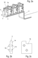
- Each of the double conductor connections of the Fig. 1a or 2a composed of the conductor connections 2a, b; 3a, b and 4a, b has two of the spring supports 6, 6' and two of the clamping springs 7, 7'.
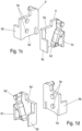
- one form-locking means is designed as a pin 6e and the corresponding form-locking means as corresponding holes 6e' ( Fig. 1 c) and d) ) which serve for clamping (and/or alternatively, if the mounting means are designed as locking means: locking) reception of the pins 6e.
- These form-locking means are preferably formed on the sides of the rear walls 6a, 6a' facing away from the spring holding contours. In this way, the rear walls 6a and 6a ⁇ can be arranged next to one another and fastened to one another, so that a type of double spring carrier is formed, on which one of the clamping springs 7, 7' can be arranged on two sides facing away from one another or is arranged in the assembled state.
- the spring supports 6 and 6' are preferably designed symmetrically relative to a plane XY, which runs between the adjacent rear walls, except for the mounting means.
- the mounting means of the spring supports 6 and 6' work together.
- the mounting means of the spring support 6 are each designed as the pin(s) 6e on the rear wall of the base wall 6a on the side facing away from the clamping spring 7.
- the mounting means of the spring supports 6' are designed as the corresponding hole(s) 6e ⁇ . In this way, the spring supports 6 and 6' can be combined to form a type of double spring support ( Fig. 1b , 1c, d ) so that their back walls lie against each other and their mounting hardware holds them together.
- the individual spring supports can easily be combined to form double spring supports.
- Two of the clamping springs 7 can then be placed and pre-assembled on the spring supports 6, 6' or on the assembled double spring supports made up of these spring supports 6 and 6'.
- the double spring supports made up of the two spring supports 6, 6' with the two clamping springs 7, 7' can be placed from above on the busbar 8 with the clamping cages 5 attached to it.
- This busbar 8 can then be arranged in a higher-level housing and locked there in turn using suitable additional mounting means such as locking edges or the like, which is explained in more detail below.
- the respective spring carrier 6, 6' and the clamping cage 5, 5' form a rectangular closed geometry in plan view with the two rear walls 5a, 5a'; 6a, 6a' and the side walls 5b, 6b or 5c, 6c; 5b', 6b' or 5c', 6c'.
- the spring carrier 6 and the clamping cages 5 interlock and form a body that is rectangular in plan view.
- the clamping spring 7 and a conductor to be connected are thus well protected.
- fine-stranded conductors can also be easily connected in this way due to the good conductor guidance function.
- the clamping cage 5 could also be further reduced, for example it could be limited to a single contact leg on which the clamping leg 7a is supported and which is connected to the busbar 8 in one piece or via a connection such as a soldering or welding point (not shown).
- the intermediate piece 9 can have one or more pins 9b on one side of the base wall 9a as mounting means, in particular form-locking means, and corresponding holes 9c on the other side as mounting means, in particular form-locking means. These interact with the mounting means, in particular form-locking means, here pins and holes of the spring supports 6 and 6'. In this way, the intermediate piece 9 can be placed between the base walls 6a and 6a' of the spring supports 6 and 6' of the double spring supports (see Fig. 1a ).
- the width of the intermediate wall 9 can be varied, so that double spring carriers of different widths can be formed in a simple manner (not shown here).
- the intermediate wall 9 itself could also form a spring carrier with the appropriate contour, so that a clamping spring and at least one central connection for conductors could be formed on it (not shown here).
- connection device of the Fig. 1 (or the Fig. 2 ) with several double conductor connections, which are accommodated in a small space on a busbar 8.
- This connection device can be integrated into a housing, for example a terminal block housing (in Fig. 1 not shown, but see purely illustrative Fig. 4 , 5 and 6 ), with at least a corresponding amount of free space.
- the mounting means, in particular the form-locking means, of the spring supports are arranged at such different positions on the rear walls of the spring supports 6, 6' that an overall offset arrangement of the two individual conductor connections 2a, 2b to 4a, 4b of the higher-level double conductor connections in the main extension direction Y of the busbar 8 results.
- an intermediate piece 9 can be used to vary the width. If the individual conductor connection 2a, 2b is arranged offset from its "neighbor" in the busbar direction Y in this way, it is possible to contact not only one conductor but also a wider test plug or the like in each of the two conductor connections 2a, 2b.
- the term "conductor connection” is therefore not to be interpreted as being limited to the connection of conductors but rather states that the basic suitability for connecting a conductor is given.
- the spring supports 6 or 6' are not assembled to form double spring supports or even triple or quadruple spring supports. Single conductor connections are formed and installed in this way.
- the housing used here is preferably a series terminal housing 10 with at least one free space 11 or several free spaces 11.
- This free space 11 or the free spaces 11 in the housing, in particular the series terminal housing is/are dimensioned such that a busbar 8' can be inserted into the housing 10, on which one or preferably several individual conductor connections 2a, 2b, 2c are arranged in a row, each of which has one of the spring supports 6, one of the clamping cages 5 and one of the clamping springs 7.
- the double conductor connections of the Fig.1 to 3 could be inserted into an appropriately dimensioned housing (not shown here).
- the housing 10 Perpendicular to a housing rear wall 15, the housing 10 has wall sections 16 which separate the free spaces 11 from one another and limit them laterally.
- the spring carrier 6 and the clamping cage 5 in the free space 11 each form a circumferentially closed geometry in plan view.
- the clamping spring 7 and a conductor to be connected are thus well protected.
- one or more conductor connection mounting means can be provided in the area of the free spaces 11, which interact with corresponding conductor connection mounting means(s) on the conductor connections.
- holes 18 for example in the housing rear wall 15, which can be connected to the corresponding conductor connection mounting means on the conductor connections - e.g. pins 19 ( Fig. 5b ) - the spring carrier 6.
- locking edges or the like for example locking pins 20 in the free space 11, e.g. protruding from the housing rear wall 15, can also be provided, which interact with corresponding locking recesses 21 on the spring carriers 6.
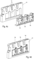
- the spring supports 6 for several individual conductor connections in series directly to form a single part.
- the base wall extends over several of the spring supports 6 (see Fig. 6a - c), so that several clamping springs can be arranged on it.
- the spring supports 6 could also be individually provided with locking pins for just one single clamping spring 7.
- conductor insertion openings 12 and openings 13 for handles or screwdrivers or the like can also be provided for opening the clamping point between the respective clamping leg 7b and the respective clamping cage side wall 5b.
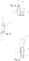
- one of the mounting means is designed as a locking means as one or more projections 17 on one or more of the clamping cages 5.
- One or more corresponding locking means are then formed in the housing 10, on which the projection(s) 17 can be locked on the clamping cage(s) 5. This is additionally illustrated in Fig. 1g .
- one or more clamping springs 7 are first placed on the spring carrier(s) 6 ( Fig. 4a and b ).
- the spring carrier(s) 6 with the clamping spring(s) 7 are then placed on the busbar 8, to which the clamping cages 5 have previously been attached.
- the busbars 8 with the conductor connections are easily pre-assembled and can be inserted as a pre-assembled unit into the terminal block housing 10, where the mounting means on this housing and on the spring carrier(s) 6 interact.
- the number of individual conductor connections of the terminal block can be easily varied. Several of the busbars 8, 8' with conductor connections can also be inserted into the housing, in particular the terminal block housing 10.
- plastic part - spring carrier 6 or 6' - can be used for both the double-conductor connection and the single-conductor connection.
- the spring receiving contour 6d or another contour on the spring carrier 6 can also be designed in such a way that a locking engagement in a locking hole 14 or the like on the clamping cage 5 is realized. This facilitates the pre-assembly of the spring carrier on the clamping cage 5 and thus on the busbar 8.
- connection device 1 conductor connections 2a, 2b; 3a, 3b, 4a, 4b clamping cage 5.5' clamp cage back wall 5a, 5a' clamp cage side walls 5b, 5c; 5b', 5c' clamp cage base 5d, 5d' spring carrier 6, 6' foundation wall 6a, 6a' side walls 6b, 6c; 6b', 6c' spring retaining contour 6d, 6d' cones 6e' clamping spring 7 support leg 7a clamping leg 7b spring back 7c busbar 8 intermediate piece 9 foundation wall 9a cones 9b holes 9c terminal block housing 10 open space 11 conductor insertion openings 12 openings 13 Rastloch 14 rear panel of the case 15 wall sections 16 projections 17 holes 18 cones 19 locking pin 20 recesses 21 Direction X, Y, Z angle ⁇ , ⁇
Landscapes
- Connections Arranged To Contact A Plurality Of Conductors (AREA)
- Coupling Device And Connection With Printed Circuit (AREA)
- Details Of Connecting Devices For Male And Female Coupling (AREA)
Claims (13)
- Dispositif de connexion (1) pour conducteur, le dispositif de connexion présentant au moins les éléments suivants:a. plusieurs connecteurs pour conducteurs simples (2a, 2b; 3a, 3b, 4a, 4b) réalisés sous la forme de connecteurs à enfichage direct, ce pour quoi chacun des connecteurs pour conducteurs simples (2a, 2b; 3a, 3b, 4a, 4b) présente respectivementi. un élément de contact métallique, en particulier une cage de serrage métallique (5 ou 5'),ii. un support à ressort (6 ou 6') en matériau non conducteur, en particulier en matière plastique non conductrice,iii. ainsi qu'un ressort de serrage (7),b. une barre conductrice (8) avec une direction d'extension principale, sur laquelle l'élément de contact est fixé,c. deux de la pluralité de connecteurs pour conducteurs simples sont respectivement réunis en connecteurs pour conducteurs doubles sur la barre conductrice (8) et plusieurs des connecteurs pour conducteurs doubles sont disposés les uns derrière les autres sur la barre conductrice (8) dans le sens d'extension principal de la barre conductrice (8),
caractérisé en ce qued. les multiples supports à ressort (6, 6') en matériau non conducteur sont fixés respectivement à au moins un élément de réception correspondant en matériau non conducteur,e. un ou plusieurs moyens de montage pour le montage du support à ressort respectif sur un élément de réception correspondant respectif en matériau non conducteur étant réalisé(s) sur les plusieurs supports à ressort (6) en matériau non conducteur, etf. l'élément de réception respectif pour le support à ressort respectif (6) étant respectivement un autre support à ressort (6'), ou en ce que l'élément de réception respectif est une pièce intermédiaire (9) qui est placée respectivement sur l'au moins un des supports à ressort (6) et sur l'autre respectif des supports à ressort (6a') du connecteur pour conducteur double respectif. - Dispositif de connexion selon la revendication 1, caractérisé en ce que le ou les moyens de montage sur le support à ressort respectif (6) sont un ou plusieurs moyens de liaison par la forme et en ce que des moyens de liaison par la forme correspondants sont prévus sur l'élément de réception, en particulier sur l'autre support à ressort (6'), de préférence de telle sorte que les moyens de liaison par la forme correspondants sont réalisés sous forme de tenons (6e) et de trous (6e').
- Dispositif de connexion selon l'une des revendications précédentes, caractérisé en ce que le ou les moyens de montage sur le support à ressort respectif (6) sont un ou plusieurs moyens d'encliquetage et en ce que des moyens d'encliquetage antagonistes correspondants sont prévus sur l'élément de réception, en particulier sur l'autre support à ressort (6').
- Dispositif de connexion selon l'une des revendications précédentes, caractérisé en ce que les cages de serrage (5 ou 5') présentent chacune, en vue de dessus, une forme en U avec une paroi arrière de cage de serrage (5a ou 5a') et deux parois latérales de cage de serrage (5b, 5c ou 5b', 5c') s'étendant perpendiculairement à celle-ci et, de préférence, une paroi de base ou un socle de base (5d ou 5d') s'étendant perpendiculairement à la paroi arrière de cage de serrage (5a ou 5a') et aux parois latérales de cage de serrage (5b, c) pour la fixation de la cage de serrage respective (5 ou 5') sur la barre conductrice (8).
- Dispositif de connexion selon l'une des revendications précédentes, caractérisé en ce que les supports à ressort (6 ou 6') présentent chacun, en vue de dessus, une forme en U avec une paroi de base (6a ou 6a') et deux parois latérales (6b, 6c ou 6b', 6c') s'étendant perpendiculairement à celle-ci.
- Dispositif de connexion selon l'une des revendications précédentes, caractérisé en ce que les supports à ressort (6 ou 6') et les cages de serrage (5 ou 5') sont assemblés en forme de U respectivement pour former un corps ayant un contour rectangulaire en vue de dessus.
- Dispositif de connexion selon l'une des revendications précédentes, caractérisé en ce que les supports à ressort (6 ou 6') présentent un ou plusieurs contours de retenue de ressort (6d ou 6d') s'étendant perpendiculairement à la paroi de base (6a), de sorte qu'un ressort de serrage (7) peut être posé sur chacun d'eux, qui est réalisé en forme de V et présente une branche d'appui (7a) et une branche de serrage (7b) disposée à angle aigu par rapport à celle-ci selon un angle (10° < α < 90°), la branche d'appui (7a) et la branche de serrage (7b) étant reliées entre elles par un dos de ressort (7c).
- Dispositif de raccordement selon l'une des revendications précédentes, caractérisé en ce que le dos de ressort (7c) du ressort de serrage respectif recouvre respectivement le contour de retenue de ressort (6d, 6d') du support à ressort (6, 6').
- Dispositif de connexion selon l'une des revendications précédentes, caractérisé en ce que respectivement deux des connecteurs pour conducteurs simples (2a, 3a, ...) sont assemblés pour former les connecteurs de conducteurs doubles avec alors deux supports à ressort (6, 6') assemblés sur les moyens de montage correspondants, deux des ressorts de serrage (7) et deux des cages de serrage (5, 5').
- Dispositif de connexion selon la revendication 9, caractérisé en ce que les deux connecteurs pour conducteurs simples (2a, 3a, ...) du connecteur pour conducteur double présentent des points de serrage situés au même endroit dans le sens d'extension principal (Y) de la barre conductrice (8), ou que les deux connecteurs pour conducteurs simples (2a, 3a, ...) du connecteur pour conducteur double présentent des points de serrage décalés dans la direction d'extension principale (Y) de la barre conductrice (8).
- Dispositif de connexion selon l'une des revendications précédentes, caractérisé en ce que la pièce intermédiaire (9) comporte de part et d'autre des moyens de montage configurés en correspondance avec les moyens de montage du support à ressort (6) pour monter deux des supports à ressort (6) sur la pièce intermédiaire (9).
- Dispositif de connexion selon l'une des revendications 3 à 11 précédentes, caractérisé en ce que les moyens d'encliquetage sont formés comme une ou plusieurs saillies (17) sur une ou plusieurs des cages de serrage (5) et en ce qu'un ou plusieurs moyens correspondants parmi les moyens d'encliquetage, par exemple un ou plusieurs bords d'encliquetage, est/sont formés dans le boîtier (10), sur lequel/lesquels la ou les saillies (17) peut/peuvent être encliquetée(s).
- Bornier ou fiche avec un boîtier et au moins un dispositif de connexion selon l'une des revendications précédentes.
Applications Claiming Priority (2)
| Application Number | Priority Date | Filing Date | Title |
|---|---|---|---|
| DE202015105022.4U DE202015105022U1 (de) | 2015-09-22 | 2015-09-22 | Anschlussvorrichtung für Leiter |
| PCT/EP2016/071925 WO2017050643A1 (fr) | 2015-09-22 | 2016-09-16 | Dispositif de connexion pour conducteur |
Publications (2)
| Publication Number | Publication Date |
|---|---|
| EP3353859A1 EP3353859A1 (fr) | 2018-08-01 |
| EP3353859B1 true EP3353859B1 (fr) | 2024-10-23 |
Family
ID=56940051
Family Applications (1)
| Application Number | Title | Priority Date | Filing Date |
|---|---|---|---|
| EP16766546.2A Active EP3353859B1 (fr) | 2015-09-22 | 2016-09-16 | Dispositif de connexion pour conducteur |
Country Status (5)
| Country | Link |
|---|---|
| US (1) | US10396476B2 (fr) |
| EP (1) | EP3353859B1 (fr) |
| CN (1) | CN108352626B (fr) |
| DE (1) | DE202015105022U1 (fr) |
| WO (1) | WO2017050643A1 (fr) |
Families Citing this family (11)
| Publication number | Priority date | Publication date | Assignee | Title |
|---|---|---|---|---|
| EP3460918A1 (fr) * | 2017-09-20 | 2019-03-27 | Delphi Technologies, Inc. | Connecteur électrique |
| EP3460917A1 (fr) | 2017-09-20 | 2019-03-27 | Delphi Technologies, Inc. | Connecteur électrique |
| DE202017107209U1 (de) * | 2017-11-28 | 2019-03-04 | Weidmüller Interface GmbH & Co. KG | Anschlussvorrichtung zum Anschluss eines Leiterendes |
| DE102018102699A1 (de) * | 2018-02-07 | 2019-08-08 | Wago Verwaltungsgesellschaft Mbh | Anschlussbaustein zum Anschließen eines elektrischen Leiters sowie Einrichtung mit einem externen Stromschienenstück und einem Anschlussbaustein |
| WO2019215953A1 (fr) * | 2018-05-08 | 2019-11-14 | 富士電機機器制御株式会社 | Support de borne de connexion, équipement électrique |
| FR3084214B1 (fr) * | 2018-07-17 | 2020-10-09 | Schneider Electric Ind Sas | Dispositif de connexion electrique |
| US11837812B2 (en) * | 2018-12-03 | 2023-12-05 | Connectwell Industries Pvt. Ltd. | Connecting terminal to produce an electric connection |
| DE202018107130U1 (de) * | 2018-12-13 | 2020-03-18 | Wago Verwaltungsgesellschaft Mbh | Leiteranschlussklemme |
| DE202019101330U1 (de) * | 2019-03-08 | 2020-06-09 | Wago Verwaltungsgesellschaft Mbh | Kontakteinsatz einer Leiteranschlussklemme und Leiteranschlussklemme |
| EP4037104B1 (fr) | 2021-01-27 | 2024-11-20 | Tyco Electronics France SAS | Bloc terminal comprenant une barre conductrice avec une partie latérale |
| DE102024121640A1 (de) * | 2024-07-30 | 2026-02-05 | Weidmüller Interface GmbH & Co. KG | Anschlussblock aus mehreren Reihenklemmen mit einer Mehrzahl von Anschlussklemmen in Direktsteck-Druckfedertechnik |
Citations (2)
| Publication number | Priority date | Publication date | Assignee | Title |
|---|---|---|---|---|
| DE4438802C1 (de) * | 1994-10-31 | 1996-03-21 | Weidmueller Interface | Verteilerleisten mit Querverteilung der elektrischen Leistung (II) |
| DE102011115637A1 (de) * | 2011-06-21 | 2012-12-27 | Phoenix Contact Gmbh & Co. Kg | Elektrische Anschlussklemme |
Family Cites Families (26)
| Publication number | Priority date | Publication date | Assignee | Title |
|---|---|---|---|---|
| US3135822A (en) * | 1961-10-30 | 1964-06-02 | Advance Transformer Co | Ballast with push-in terminal block |
| US4722701A (en) * | 1986-09-29 | 1988-02-02 | Todd Engineering Sales, Inc. | Fuse block for miniature plug-in blade-type fuse |
| DE19803085A1 (de) * | 1998-01-28 | 1999-08-05 | Metz Albert Ria Electronic | Anschlußklemme |
| DE19823648C1 (de) * | 1998-05-27 | 1999-11-04 | Metz Albert Ria Electronic | Anschlußklemme |
| DE19832593C1 (de) * | 1998-07-09 | 2000-01-05 | Gerd Conrad | Initiatoren-Aktoren-Klemme |
| DE10023851A1 (de) * | 2000-05-16 | 2001-11-22 | Moeller Gmbh | Anschlußklemme |
| US6422884B1 (en) * | 2000-06-27 | 2002-07-23 | Sentinel Lighting Wiring Systems, Inc. | Pre-wired circuit component for flexible wiring system |
| DE10290399T5 (de) | 2001-03-09 | 2009-01-08 | Matsushita Electric Works, Ltd., Kadoma | Drahtverbindungsvorrichtung für Leiterplatte |
| JP4208130B2 (ja) * | 2002-06-20 | 2009-01-14 | タイコ エレクトロニクス アンプ ゲゼルシャフト ミット ベシュレンクテル ハウツンク | プラグ型電気コネクタ |
| DE202004000523U1 (de) * | 2004-01-15 | 2005-05-25 | Weidmüller Interface GmbH & Co. KG | Anschlußsystem zum Anschluß elektrischer Leiter an ein elektrisches Gerät |
| DE102005050267B4 (de) * | 2005-10-20 | 2007-12-27 | Phoenix Contact Gmbh & Co. Kg | Reihenklemme |
| DE102006005260A1 (de) * | 2006-02-02 | 2007-08-16 | Phoenix Contact Gmbh & Co. Kg | Elektrische Anschlußklemme |
| DE102006049773B4 (de) * | 2006-10-21 | 2009-01-08 | Abb Ag | Modulares Installationsschaltgerät |
| US7785134B2 (en) * | 2008-12-30 | 2010-08-31 | General Electric Company | Contact terminal for conductors |
| DE102009004513A1 (de) | 2009-01-09 | 2010-07-22 | Phoenix Contact Gmbh & Co. Kg | Klemmfeder für eine Federkraftklemme |
| DE102009050367A1 (de) * | 2009-10-22 | 2011-04-28 | Phoenix Contact Gmbh & Co. Kg | Federkraftanschlussklemme |
| EP2534734A4 (fr) | 2010-02-10 | 2013-11-27 | Optime As | Dispositif de connexion pour transformateurs, commandes électroniques et connexions d'éclairage |
| DE102011056410B4 (de) * | 2011-12-14 | 2013-06-27 | Wago Verwaltungsgesellschaft Mbh | Anschlussklemme |
| DE202012103314U1 (de) * | 2012-08-30 | 2013-12-02 | Weidmüller Interface GmbH & Co. KG | Anschlussvorrichtung für einen Leiter |
| SG2012065942A (en) * | 2012-09-05 | 2014-04-28 | Schneider Electric South East Asia Hq Pte Ltd | An electrical connector and a connector assembly |
| JP6419191B2 (ja) | 2013-09-16 | 2018-11-07 | ヴァイトミュラー インターフェイス ゲゼルシャフト ミット ベシュレンクテル ハフツング ウント コンパニー コマンデイトゲゼルシャフト | ダイレクトプラグイン端子用の端子ケージ |
| DE102013110475A1 (de) * | 2013-09-23 | 2015-03-26 | Phoenix Contact Gmbh & Co. Kg | Elektrische Anschlussklemme |
| DE102014102517B4 (de) * | 2014-02-26 | 2021-06-10 | Wago Verwaltungsgesellschaft Mbh | Verbindungsklemme und Federkraftklemmkontakt hierzu |
| US9553387B2 (en) * | 2014-07-15 | 2017-01-24 | Industria Lombarda Materiale Elettrico—I.L.M.E. S.P.A. | Electrical connecting device with spring connection element and compact actuator and multi-pole plug connector comprising a plurality of said spring contacts |
| CN204558667U (zh) * | 2015-04-11 | 2015-08-12 | 江门市创艺电器有限公司 | 一种接线端子连接器 |
| DE202016101051U1 (de) * | 2016-02-29 | 2017-05-30 | Wago Verwaltungsgesellschaft Mbh | Reihenklemme |
-
2015
- 2015-09-22 DE DE202015105022.4U patent/DE202015105022U1/de not_active Expired - Lifetime
-
2016
- 2016-09-16 US US15/761,177 patent/US10396476B2/en active Active
- 2016-09-16 CN CN201680054617.9A patent/CN108352626B/zh not_active Expired - Fee Related
- 2016-09-16 WO PCT/EP2016/071925 patent/WO2017050643A1/fr not_active Ceased
- 2016-09-16 EP EP16766546.2A patent/EP3353859B1/fr active Active
Patent Citations (2)
| Publication number | Priority date | Publication date | Assignee | Title |
|---|---|---|---|---|
| DE4438802C1 (de) * | 1994-10-31 | 1996-03-21 | Weidmueller Interface | Verteilerleisten mit Querverteilung der elektrischen Leistung (II) |
| DE102011115637A1 (de) * | 2011-06-21 | 2012-12-27 | Phoenix Contact Gmbh & Co. Kg | Elektrische Anschlussklemme |
Also Published As
| Publication number | Publication date |
|---|---|
| EP3353859A1 (fr) | 2018-08-01 |
| CN108352626A (zh) | 2018-07-31 |
| US20180277968A1 (en) | 2018-09-27 |
| CN108352626B (zh) | 2021-05-25 |
| US10396476B2 (en) | 2019-08-27 |
| WO2017050643A1 (fr) | 2017-03-30 |
| DE202015105022U1 (de) | 2016-12-23 |
Similar Documents
| Publication | Publication Date | Title |
|---|---|---|
| EP3353859B1 (fr) | Dispositif de connexion pour conducteur | |
| EP3316402B1 (fr) | Douille de contact plate | |
| DE102017119287B4 (de) | Modularer Steckverbinder für Leiterplatten | |
| EP3075035B1 (fr) | Support de contact de connecteur | |
| DE60314100T2 (de) | Monatageverfahren eines elektrischen Verbinders | |
| DE102015114814B4 (de) | System aus Steckverbinder-Modulrahmen und Adapterelementen sowie modularen Steckverbinder mit einem solchen System | |
| DE202012010735U1 (de) | Modularer Steckverbinder | |
| DE102011056043B4 (de) | Stromschienenabgriffelement | |
| EP2823536B1 (fr) | Fiche de raccordement avec pontet de conducteur de protection | |
| EP3734771B1 (fr) | Ensemble comprenant un connecteur électrique et un élément fonctionnel | |
| EP3164911A1 (fr) | Fiche de raccordement | |
| EP4014287B1 (fr) | Connecteur femelle de carte de circuit imprimé xlr à 8+2 voies | |
| EP0913884B1 (fr) | Dispositif de bornes en rangée | |
| DE102009030645B4 (de) | Brückerelement und Set aus zumindest einem Klemmelement und Brückerelement | |
| EP3490075A1 (fr) | Ensemble composé de connecteur enfichable et d'élément de retenue ainsi que connecteur enfichable et élément de retenue correspondant | |
| DE2547166A1 (de) | Elektrische verbinderanordnung | |
| EP2393160A1 (fr) | Bornier de répartition de forme étagée | |
| EP3714512B1 (fr) | Module en nid d'abeille | |
| EP3353860B1 (fr) | Boîtier de connexion pourvu d'un dispositif de connexion pour conducteurs | |
| DE2750540C2 (fr) | ||
| DE10212511B4 (de) | Querverbinder für Reihenklemmen | |
| AT13901U1 (de) | Anschluss- oder Verbindungsklemme für elektrische Leiter, sowie Leuchte | |
| DE3542349C2 (fr) | ||
| EP1587166B1 (fr) | Bloc de répartition | |
| EP3925034B1 (fr) | Barre de serrage pour connecteurs enfichables modulaires |
Legal Events
| Date | Code | Title | Description |
|---|---|---|---|
| STAA | Information on the status of an ep patent application or granted ep patent |
Free format text: STATUS: THE INTERNATIONAL PUBLICATION HAS BEEN MADE |
|
| PUAI | Public reference made under article 153(3) epc to a published international application that has entered the european phase |
Free format text: ORIGINAL CODE: 0009012 |
|
| STAA | Information on the status of an ep patent application or granted ep patent |
Free format text: STATUS: REQUEST FOR EXAMINATION WAS MADE |
|
| 17P | Request for examination filed |
Effective date: 20180413 |
|
| AK | Designated contracting states |
Kind code of ref document: A1 Designated state(s): AL AT BE BG CH CY CZ DE DK EE ES FI FR GB GR HR HU IE IS IT LI LT LU LV MC MK MT NL NO PL PT RO RS SE SI SK SM TR |
|
| AX | Request for extension of the european patent |
Extension state: BA ME |
|
| DAV | Request for validation of the european patent (deleted) | ||
| DAX | Request for extension of the european patent (deleted) | ||
| RAP1 | Party data changed (applicant data changed or rights of an application transferred) |
Owner name: WEIDMUELLER INTERFACE GMBH & CO. KG |
|
| STAA | Information on the status of an ep patent application or granted ep patent |
Free format text: STATUS: EXAMINATION IS IN PROGRESS |
|
| 17Q | First examination report despatched |
Effective date: 20200714 |
|
| GRAP | Despatch of communication of intention to grant a patent |
Free format text: ORIGINAL CODE: EPIDOSNIGR1 |
|
| STAA | Information on the status of an ep patent application or granted ep patent |
Free format text: STATUS: GRANT OF PATENT IS INTENDED |
|
| INTG | Intention to grant announced |
Effective date: 20240607 |
|
| GRAS | Grant fee paid |
Free format text: ORIGINAL CODE: EPIDOSNIGR3 |
|
| P01 | Opt-out of the competence of the unified patent court (upc) registered |
Free format text: CASE NUMBER: APP_44310/2024 Effective date: 20240730 |
|
| GRAA | (expected) grant |
Free format text: ORIGINAL CODE: 0009210 |
|
| STAA | Information on the status of an ep patent application or granted ep patent |
Free format text: STATUS: THE PATENT HAS BEEN GRANTED |
|
| AK | Designated contracting states |
Kind code of ref document: B1 Designated state(s): AL AT BE BG CH CY CZ DE DK EE ES FI FR GB GR HR HU IE IS IT LI LT LU LV MC MK MT NL NO PL PT RO RS SE SI SK SM TR |
|
| REG | Reference to a national code |
Ref country code: GB Ref legal event code: FG4D Free format text: NOT ENGLISH |
|
| REG | Reference to a national code |
Ref country code: CH Ref legal event code: EP |
|
| REG | Reference to a national code |
Ref country code: DE Ref legal event code: R096 Ref document number: 502016016760 Country of ref document: DE |
|
| REG | Reference to a national code |
Ref country code: IE Ref legal event code: FG4D Free format text: LANGUAGE OF EP DOCUMENT: GERMAN |
|
| REG | Reference to a national code |
Ref country code: LT Ref legal event code: MG9D |
|
| REG | Reference to a national code |
Ref country code: NL Ref legal event code: MP Effective date: 20241023 |
|
| PG25 | Lapsed in a contracting state [announced via postgrant information from national office to epo] |
Ref country code: NL Free format text: LAPSE BECAUSE OF FAILURE TO SUBMIT A TRANSLATION OF THE DESCRIPTION OR TO PAY THE FEE WITHIN THE PRESCRIBED TIME-LIMIT Effective date: 20241023 |
|
| PG25 | Lapsed in a contracting state [announced via postgrant information from national office to epo] |
Ref country code: NL Free format text: LAPSE BECAUSE OF FAILURE TO SUBMIT A TRANSLATION OF THE DESCRIPTION OR TO PAY THE FEE WITHIN THE PRESCRIBED TIME-LIMIT Effective date: 20241023 |
|
| PG25 | Lapsed in a contracting state [announced via postgrant information from national office to epo] |
Ref country code: IS Free format text: LAPSE BECAUSE OF FAILURE TO SUBMIT A TRANSLATION OF THE DESCRIPTION OR TO PAY THE FEE WITHIN THE PRESCRIBED TIME-LIMIT Effective date: 20250223 Ref country code: HR Free format text: LAPSE BECAUSE OF FAILURE TO SUBMIT A TRANSLATION OF THE DESCRIPTION OR TO PAY THE FEE WITHIN THE PRESCRIBED TIME-LIMIT Effective date: 20241023 Ref country code: PT Free format text: LAPSE BECAUSE OF FAILURE TO SUBMIT A TRANSLATION OF THE DESCRIPTION OR TO PAY THE FEE WITHIN THE PRESCRIBED TIME-LIMIT Effective date: 20250224 |
|
| PG25 | Lapsed in a contracting state [announced via postgrant information from national office to epo] |
Ref country code: FI Free format text: LAPSE BECAUSE OF FAILURE TO SUBMIT A TRANSLATION OF THE DESCRIPTION OR TO PAY THE FEE WITHIN THE PRESCRIBED TIME-LIMIT Effective date: 20241023 |
|
| PG25 | Lapsed in a contracting state [announced via postgrant information from national office to epo] |
Ref country code: BG Free format text: LAPSE BECAUSE OF FAILURE TO SUBMIT A TRANSLATION OF THE DESCRIPTION OR TO PAY THE FEE WITHIN THE PRESCRIBED TIME-LIMIT Effective date: 20241023 |
|
| PG25 | Lapsed in a contracting state [announced via postgrant information from national office to epo] |
Ref country code: ES Free format text: LAPSE BECAUSE OF FAILURE TO SUBMIT A TRANSLATION OF THE DESCRIPTION OR TO PAY THE FEE WITHIN THE PRESCRIBED TIME-LIMIT Effective date: 20241023 |
|
| PG25 | Lapsed in a contracting state [announced via postgrant information from national office to epo] |
Ref country code: NO Free format text: LAPSE BECAUSE OF FAILURE TO SUBMIT A TRANSLATION OF THE DESCRIPTION OR TO PAY THE FEE WITHIN THE PRESCRIBED TIME-LIMIT Effective date: 20250123 |
|
| PG25 | Lapsed in a contracting state [announced via postgrant information from national office to epo] |
Ref country code: LV Free format text: LAPSE BECAUSE OF FAILURE TO SUBMIT A TRANSLATION OF THE DESCRIPTION OR TO PAY THE FEE WITHIN THE PRESCRIBED TIME-LIMIT Effective date: 20241023 Ref country code: GR Free format text: LAPSE BECAUSE OF FAILURE TO SUBMIT A TRANSLATION OF THE DESCRIPTION OR TO PAY THE FEE WITHIN THE PRESCRIBED TIME-LIMIT Effective date: 20250124 |
|
| PG25 | Lapsed in a contracting state [announced via postgrant information from national office to epo] |
Ref country code: PL Free format text: LAPSE BECAUSE OF FAILURE TO SUBMIT A TRANSLATION OF THE DESCRIPTION OR TO PAY THE FEE WITHIN THE PRESCRIBED TIME-LIMIT Effective date: 20241023 |
|
| PG25 | Lapsed in a contracting state [announced via postgrant information from national office to epo] |
Ref country code: RS Free format text: LAPSE BECAUSE OF FAILURE TO SUBMIT A TRANSLATION OF THE DESCRIPTION OR TO PAY THE FEE WITHIN THE PRESCRIBED TIME-LIMIT Effective date: 20250123 |
|
| PG25 | Lapsed in a contracting state [announced via postgrant information from national office to epo] |
Ref country code: SM Free format text: LAPSE BECAUSE OF FAILURE TO SUBMIT A TRANSLATION OF THE DESCRIPTION OR TO PAY THE FEE WITHIN THE PRESCRIBED TIME-LIMIT Effective date: 20241023 |
|
| PG25 | Lapsed in a contracting state [announced via postgrant information from national office to epo] |
Ref country code: DK Free format text: LAPSE BECAUSE OF FAILURE TO SUBMIT A TRANSLATION OF THE DESCRIPTION OR TO PAY THE FEE WITHIN THE PRESCRIBED TIME-LIMIT Effective date: 20241023 |
|
| PG25 | Lapsed in a contracting state [announced via postgrant information from national office to epo] |
Ref country code: EE Free format text: LAPSE BECAUSE OF FAILURE TO SUBMIT A TRANSLATION OF THE DESCRIPTION OR TO PAY THE FEE WITHIN THE PRESCRIBED TIME-LIMIT Effective date: 20241023 |
|
| PG25 | Lapsed in a contracting state [announced via postgrant information from national office to epo] |
Ref country code: RO Free format text: LAPSE BECAUSE OF FAILURE TO SUBMIT A TRANSLATION OF THE DESCRIPTION OR TO PAY THE FEE WITHIN THE PRESCRIBED TIME-LIMIT Effective date: 20241023 |
|
| REG | Reference to a national code |
Ref country code: DE Ref legal event code: R097 Ref document number: 502016016760 Country of ref document: DE |
|
| PG25 | Lapsed in a contracting state [announced via postgrant information from national office to epo] |
Ref country code: SK Free format text: LAPSE BECAUSE OF FAILURE TO SUBMIT A TRANSLATION OF THE DESCRIPTION OR TO PAY THE FEE WITHIN THE PRESCRIBED TIME-LIMIT Effective date: 20241023 |
|
| PG25 | Lapsed in a contracting state [announced via postgrant information from national office to epo] |
Ref country code: CZ Free format text: LAPSE BECAUSE OF FAILURE TO SUBMIT A TRANSLATION OF THE DESCRIPTION OR TO PAY THE FEE WITHIN THE PRESCRIBED TIME-LIMIT Effective date: 20241023 |
|
| PG25 | Lapsed in a contracting state [announced via postgrant information from national office to epo] |
Ref country code: IT Free format text: LAPSE BECAUSE OF FAILURE TO SUBMIT A TRANSLATION OF THE DESCRIPTION OR TO PAY THE FEE WITHIN THE PRESCRIBED TIME-LIMIT Effective date: 20241023 |
|
| PLBE | No opposition filed within time limit |
Free format text: ORIGINAL CODE: 0009261 |
|
| STAA | Information on the status of an ep patent application or granted ep patent |
Free format text: STATUS: NO OPPOSITION FILED WITHIN TIME LIMIT |
|
| PG25 | Lapsed in a contracting state [announced via postgrant information from national office to epo] |
Ref country code: SE Free format text: LAPSE BECAUSE OF FAILURE TO SUBMIT A TRANSLATION OF THE DESCRIPTION OR TO PAY THE FEE WITHIN THE PRESCRIBED TIME-LIMIT Effective date: 20241023 |
|
| 26N | No opposition filed |
Effective date: 20250724 |
|
| PGFP | Annual fee paid to national office [announced via postgrant information from national office to epo] |
Ref country code: DE Payment date: 20250919 Year of fee payment: 10 |