EP3356063B1 - Dispositif et procédé pour le redressage sous presse d'un produit plat métallique - Google Patents
Dispositif et procédé pour le redressage sous presse d'un produit plat métallique Download PDFInfo
- Publication number
- EP3356063B1 EP3356063B1 EP16770787.6A EP16770787A EP3356063B1 EP 3356063 B1 EP3356063 B1 EP 3356063B1 EP 16770787 A EP16770787 A EP 16770787A EP 3356063 B1 EP3356063 B1 EP 3356063B1
- Authority
- EP
- European Patent Office
- Prior art keywords
- press frame
- roll
- straightening
- roll stand
- flat product
- Prior art date
- Legal status (The legal status is an assumption and is not a legal conclusion. Google has not performed a legal analysis and makes no representation as to the accuracy of the status listed.)
- Active
Links
Images

Classifications
-
- B—PERFORMING OPERATIONS; TRANSPORTING
- B21—MECHANICAL METAL-WORKING WITHOUT ESSENTIALLY REMOVING MATERIAL; PUNCHING METAL
- B21D—WORKING OR PROCESSING OF SHEET METAL OR METAL TUBES, RODS OR PROFILES WITHOUT ESSENTIALLY REMOVING MATERIAL; PUNCHING METAL
- B21D1/00—Straightening, restoring form or removing local distortions of sheet metal or specific articles made therefrom; Stretching sheet metal combined with rolling
- B21D1/06—Removing local distortions
-
- B—PERFORMING OPERATIONS; TRANSPORTING
- B21—MECHANICAL METAL-WORKING WITHOUT ESSENTIALLY REMOVING MATERIAL; PUNCHING METAL
- B21D—WORKING OR PROCESSING OF SHEET METAL OR METAL TUBES, RODS OR PROFILES WITHOUT ESSENTIALLY REMOVING MATERIAL; PUNCHING METAL
- B21D1/00—Straightening, restoring form or removing local distortions of sheet metal or specific articles made therefrom; Stretching sheet metal combined with rolling
Definitions
- the invention relates to a device for straightening a metallic flat product, a rolling stand, in particular a horizontal rolling mill, with this device and a method for operating such a roll stand.
- Roll stands in particular horizontal rolling stands, for preferably horizontal rolling of flat metal products are well known in the art.
- quarto scaffolds with two work rolls and two back-up rolls are commonplace.
- rolling stands are used exclusively for rolling steel or non-ferrous metals on a flat track.
- Known means for straightening typically have an upper pressing frame with a plunger and a lower press frame with a table for supporting the flat product to be straightened, wherein the upper press frame is arranged above the lower press frame and both press frames are movable in the vertical direction relative to each other.
- the invention has for its object to provide a device for straightening a metallic flat product, a rolling mill with this device and a method for operating such a rolling stand, which allow an economically efficient straightening of flat products.
- the upper press frame has support elements in the region of its two narrow sides as points of application for a balancing device for the upper work roll in a roll stand; and that the lower press frame has in the region of its two narrow sides supporting elements for supporting on the uprights of the roll stand.
- metallic flat product means in the context of the present description, for example, a metal plate or a metal sheet or a metal strip.
- balancing device may not only mean separate balancing cylinders for the work rolls, but also includes a bending device, in particular bending cylinders, which perform a balancing function for the work rolls.
- the term table basically means a plate.
- the trough in the table or the plate is in the simplest case a recess.
- the table with the trough is typically attached to the lower press frame and the plunger to the upper press frame; but also the reverse arrangement is possible.
- the apparatus also called directional cassette
- a slot for a rolling stand which instead of the Work rolls can be inserted into the mill stand.
- the rolling stand is operable not only in a "rolling" mode (with built-in work rolls), but alternatively also in a "straightening press” operating mode (with a built-in insert instead of the work rolls).
- the hydraulic setting cylinders available in the (horizontal) rolling stand for the support rolls are used meaningfully to provide large straightening forces which can bring about a fundamental improvement in the straightening, in particular of thick sheets.
- the upper pressing frame is supported via supporting bolts on the lower pressing frame.
- the support pins are immersed in associated holes in the opposite pressing frame. In this way, an undesired lateral displacement of the plunger is prevented during straightening.
- the vertical positioning of the upper and lower pressing frames relative to one another takes place over those cylinders which in the rolling operation serve for bending or balancing the work rolls.
- a coupling element may be mounted for releasably coupling the straightening cassette to a roll changing device.
- roll changing device in particular a pulling or pushing device
- the Straightening cassette advantageously quite simple - typically on the operating side - in the rolling stand and retracted.
- rails are laid in the longitudinal direction of the upper and / or the lower pressing frame and the plunger and / or the table are formed on the pressing frame each as a carriage for moving on the rails in the longitudinal direction of the pressing frame.
- the upper press frame has on one of its narrow sides an upper drive device, preferably an upper spindle drive, for moving the carriage in the form of the pressure ram or the table on the rails of the upper press frame.
- an upper drive device preferably an upper spindle drive
- the lower pressing frame on one of its narrow sides, a lower drive means, preferably a lower spindle drive, for moving the carriage in the form of the table or the plunger on the rails of the lower pressing frame.
- the narrow sides of the pressing frame, where the drive devices are mounted are preferably those sides which lie on the operating side after insertion of the straightening cassette into the rolling stand, since relatively simple energy and media connections can be reversed there.
- a control device of the rolling stand is designed to provide both operating modes, that is to say the “rolling operation” and the “directional pressing operation”.
- the rolling mill operator has the option of selecting one of the two operating modes as required.
- FIG. 1 shows a perspective view of the device 100 according to the invention, also called directional cassette, for straightening a metallic flat product, For example, a sheet in a rolling stand.
- the device 100 consists of an upper pressing frame 110 and a lower pressing frame 120.
- Fig. 1 shows the straightening cassette in a disassembled state, ie not installed in a roll stand.
- the upper press frame 110 is disposed longitudinally offset from the lower press frame 120.
- the upper press frame 110 typically rests on support pins 130 on the lower press frame 120.
- the support bolts 130 are arranged in the region of the narrow sides of the press frames 110, 120 and are preferably fixedly mounted on the upper press frame.
- the upper pressing frame 110 has formed in the region of its narrow sides supporting elements 114, which serve as points of application for a balancing device, for example Balancierzylinder for the upper work roll in the rolling stand when installed in a rolling stand.
- the lower pressing frame 120 has formed in the region of its narrow sides supporting elements 124, which serve when mounted in the roll stand for supporting on the uprights of the roll stand.
- the support elements 124 are sliding elements or rollers which, during installation of the straightening cassette into the rolling stand and during removal of the straightening cassette from the rolling stand, slide onto the rails 370 for the installation and removal of the work rolls which are present anyway in the rolling stand . roll; see also Fig. 3 ,
- the longitudinal extent of the upper and lower pressing frame corresponds at least approximately to the width of the rolling stand from the drive to the operating side.
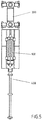
- a coupling element 140 on one end face of the device 100 can be seen for releasably coupling the device or straightening cassette to a pulling or pushing device 400.
- the pulling or pushing device 400 serves to align the straightening cassette 100 with the upper and lower pressing frames out of the frame region to move into the framework area.
- the pulling or pushing device is preferably a (rolling) changing device, in particular a roller changing locomotive, see Fig. 5 ,
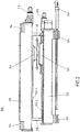
- FIG. 2 shows a longitudinal section through the inventive device 100.
- Fig. 2 shows the straightening cassette in a dismantled state with staggered upper and lower pressing frames, as described above with respect to Fig.1 described.
- rails 150-1 are preferably laid in the longitudinal direction of the upper pressing frame on its side facing the lower pressing frame.
- a plunger 112 which is designed as a carriage, arranged movable.
- rails 150-2 are also preferably arranged on the upper side facing the upper pressing frame in the longitudinal direction of the lower pressing frame.
- the rails 150-2 designed as a slide table 122 for placing the flat product to be straightened is arranged movable; see the horizontal arrows in Fig. 2 ,
- the table points, as in Fig. 1 can be seen, a trough 123, as a space in which the material of the flat product during the straightening process can be pushed in or overstretched.
- the upper press frame 110 has an upper drive 210 for moving the plunger 112 formed on the rails 150-1 of the upper press frame.
- the lower pressing frame 120 has a lower drive device 220 for moving the designed as a slide table 122.
- the drive means 210, 220 are preferably attached to those end faces of the press frames 110, 120, which in installation of the device 100 in a Roll stand on the operating side of the rolling stand.
- the drive means 210, 220 which are preferably each formed as a spindle drives, then the table 122 and the plunger 112, preferably independently of each other, along the rails 150-1, 150-2 are each suitably positioned.
- Positioning suitable means in particular, that the table 122 and the plunger 112 are moved relative to one another in such a way that the plunger 112 is positioned precisely in the region of the unevenness to be straightened in the flat product.
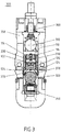
- Fig. 3 shows the rolling mill 300 according to the invention, here by way of example a four-high rolling stand with two back-up rolls 310, 320 and normally also two work rolls, which, however, in Figure 3 not shown because expanded.
- the upper back-up roll 310 and the lower back-up roll 320 are both raised.
- the inventive device 100 that is, the straightening cassette is installed in the mill stand 300.
- the lower pressing frame 120 is supported with its support elements 124 on the rails 370 for the change of the work rolls.
- the upper pressing frame 110 is detachably coupled via its supporting elements 114 to a balancing device 330 and is supported by this in the vertical direction.
- the balancer 330 normally serves to balance, that is, to compensate for the weight of the upper work roll, when the mill is operated in a rolling mode.
- Fig. 3 shows the rolling stand 300 with the built-in straightening cassette retrofitted for an inventive operating mode "straightening".
- the balancer serves for carrying, that is, for compensating the weight of the upper press frame 110 Fig. 3 initially, the raised upper support roller 310 still has no contact with the upper pressing frame 110, and the lower supporting roller 320 initially has no contact with the lower pressing frame 120; insofar shows Fig. 3 the rolling stand in a preparation state for the Richtpress memori.
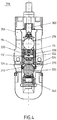
- Fig. 4 shows the mill 300 according to the invention also with built-in straightening cassette 100.
- the lower support roller 320 employed by means of a vertical adjusting device 340 from below against the lower pressing frame 120.
- the lower press frame 120 is at least slightly lifted off the rails 370 for the work roll change and supported against acting in the directional pressing operation acting in the vertical direction straightening forces.
- the upper support roller 310 is placed in a predetermined abutment position for the upper press frame 110 by means of the mechanical adjustment 360.
- the upper pressing frame 110 is employed with the aid of the balancing device 330 in a non-positive and clearance-free manner against the upper support roller 310 in the stop position.
- Said straightening of the flat product by pressing the flat product from below is selected when the hydraulic vertical adjusting device is provided at the bottom of the rolling stand for pushing the lower supporting roll 320 upwards.
- the position of plunger and trough compared to the embodiment according to the FIGS. 1 to 4 be reversed, so that in this case, theriolunotede unevenness extends downwards.
- a plan for straightening the flat product can be prepared considering data on the flat product, such as material grade, thickness and width, taking into account information about the bump, such as location of the defect, size / depth and type of defect as well optionally including a process model.
- the unevenness to be straightened in the flat product can be automatically detected, for example, with the aid of a scanner in the form of images.
- the information about the bump may then be obtained by evaluating the images of the scanner preferably be determined at least partially automatically.
- the respective current position of the flat product can be regularly monitored and corrected in the event of a detected deviation from a respective desired position.
- the result of the straightening process can be monitored and compared with a predetermined desired result. That is, it can be checked to what extent the original unevenness in the flat product has already been eliminated. With a detected insufficient quality of the judging result, i. a still insufficient removal of the unevenness, the judging can be repeated.
- the two support rollers 310, 320 and the upper and the lower pressing frame are raised again.
- the steps described above for the installation of the straightening cassette into the rolling stand are carried out in reverse order.
- All steps of the process can be performed manually or controlled. Preferably, however, they are at least partially executed automatically.
Landscapes
- Engineering & Computer Science (AREA)
- Mechanical Engineering (AREA)
- Straightening Metal Sheet-Like Bodies (AREA)
- Metal Rolling (AREA)
- Press Drives And Press Lines (AREA)
- Bending Of Plates, Rods, And Pipes (AREA)
Claims (18)
- Dispositif (100) destiné au dressage d'un produit plat métallique, présentant :un cadre de presse supérieur (110) et un cadre de presse inférieur (120) ;dans lequel le cadre de presse supérieur présente un poinçon de pression (112) et le cadre de presse inférieur présente une table (122) comprenant un creux pour que vienne s'y enfoncer le poinçon de pression, ou inversement ; etdans lequel le cadre de presse supérieur (110) est disposé à l'opposé du cadre de presse inférieur (120) et les deux cadres de presse sont à même de se déplacer l'un par rapport à l'autre ;caractériséen ce que le cadre de presse supérieur (110) présente, dans la zone de ses deux petits côtés, des éléments de support (114) à titre de points d'application pour un mécanisme faisant office de balancier pour le cylindre de travail supérieur dans une cage de laminoir ; eten ce que le cadre de presse inférieur (120) présente, dans la zone de ses deux petits côtés, des éléments d'appui (124) destinés à venir s'appuyer contre les supports de la cage de laminoir.
- Dispositif (100) selon la revendication 1, caractérisé par des axes de support (130) qui sont disposés dans la zone des deux petits côtés du cadre de presse inférieur ou du cadre de presse supérieur (110, 120) et par des alésages dans le cadre de presse respectivement opposé pour la réception des axes de support.
- Dispositif (100) selon la revendication 2, caractérisé par un élément d'accouplement (140) disposé contre un petit côté du dispositif (100), de préférence contre un petit côté du cadre de presse inférieur (110), destiné à l'accouplement amovible du à dispositif (100) un mécanisme de traction ou de poussée (400).
- Dispositif (100) selon l'une quelconque des revendications précédentes, caractérisé en ce que des rails (150-1, 150-2) sont posés dans la direction longitudinale du cadre de presse supérieur et/ou du cadre de presse inférieur (110, 120) ; et en ce que le poinçon de pression (112) de l'un des cadres de presse et/ou la table (122) comprenant le creux de l'autre cadre de presse sont réalisés respectivement sous la forme de chariots destinés à se déplacer sur les rails dans la direction longitudinale des cadres de presse.
- Dispositif (100) selon la revendication 4, caractérisé en ce que le cadre de presse supérieur (110) présente, à un de ses petits côtés, un mécanisme d'entraînement supérieur (210), de préférence un mécanisme d'entraînement supérieur à vis destiné au déplacement du chariot sous la forme du poinçon de pression (112) ou de la table le long des rails (150-1) du cadre de presse supérieur; et/ou en ce que le cadre de presse inférieur (120) présente, à un de ses petits côtés, un mécanisme d'entraînement inférieur (220), de préférence un mécanisme d'entraînement inférieur à vis destiné au déplacement du chariot sous la forme de la table (122) ou du poinçon de pression (112) le long des rails (150-2) du cadre de presse inférieur.
- Cage de laminoir (300), en particulier cage de laminoir horizontal, présentant :un cylindre d'appui supérieur et un cylindre d'appui inférieur (310, 320) ;des cylindres de travail aptes à se déployer ;un mécanisme faisant office de balancier (330) pour le cylindre de travail supérieur; etun mécanisme de déplacement vertical, de préférence hydraulique (340), pour le cylindre d'appui inférieur;caractérisée en ce que le dispositif (100) selon l'une quelconque des revendications précédentes est monté dans la cage de laminoir (300) à la place des cylindres de travail.
- Cage de laminoir selon la revendication 6, caractérisée en ce que - dans un état de départ pour une exploitation de type dressage - le cadre de presse inférieur (120) vient s'appuyer sur le cylindre d'appui inférieur; et en ce que le cadre de presse supérieur (110) vient s'appuyer par l'intermédiaire de ses éléments de support (114), sur le mécanisme (330) faisant office de balancier pour le cylindre de travail supérieur et s'est déplacé avec le mécanisme (330) faisant office de balancier contre le cylindre d'appui supérieur se trouvant dans une position de butée.
- Cage de laminoir selon l'une quelconque des revendications 6 ou 7, caractérisée en ce que l'on prévoit un mécanisme de commande destiné à la cage de laminoir pour l'exploitation de la cage de laminoir dans un mode de fonctionnement de type « laminage » pour le laminage d'un produit de laminage ou dans un mode de fonctionnement de type «dressage» qui peut être sélectionné en variante, pour le dressage du produit plat.
- Cage de laminoir selon l'une quelconque des revendications 7 à 8, caractérisé en ce qu'on prévoit, dans la cage de laminoir, des rails (370) pour un échange des cylindres de travail ; et en ce que les éléments d'appui (124) du cadre de presse inférieur (120) sont réalisés sous la forme d'éléments de glissement ou de galets pour le glissement ou le roulement sur les rails (370) à des fins d'échange des cylindres de travail.
- Procédé pour l'exploitation d'une cage de laminoir (330) selon l'une quelconque des revendications 6 à 9 dans un mode de fonctionnement de type «dressage», dans lequel le procédé - à partir d'un état de départ de la cage de laminoir pour l'exploitation de type « dressage » - présente les étapes suivantes dans lesquelles :- on introduit le produit plat dans la cage de laminoir et on positionne le produit plat qui doit être soumis au dressage par rapport à la table (122) comprenant un creux de l'un des cadres de presse d'une manière telle qu'un défaut d'égalité qui doit être supprimé s'étend dans la direction de l'autre cadre de presse supportant le poinçon de pression (112) et se trouve entre les deux cadres de presse ;- on dispose la table (122) et/ou le poinçon de presse (112) par rapport à la position du défaut d'égalité dans le produit plat par l'intermédiaire d'un déplacement transversal du poinçon de pression ou de la table d'une manière telle que le poinçon de pression, respectivement la table se retrouve au-dessus du défaut d'égalité ; et- on dresse le produit plat en soulevant le cylindre d'appui inférieur sur lequel vient s'appuyer le cadre de presse inférieur (120) à l'aide du mécanisme de déplacement vertical de préférence hydraulique pour le cylindre d'appui inférieur (320) et on comprime de cette manière le produit plat qui s'appuie sur le cadre de presse inférieur, à partir du bas, contre le poinçon de pression (112) ou contre la table sur le cadre de presse supérieur afin d'éliminer le défaut d'égalité à partir du produit plat.
- Procédé selon la revendication 10, caractérisé en ce que - après l'élimination du défaut d'égalité - les deux cylindres d'appui (310, 320) ainsi que le cadre de presse supérieur et le cadre de presse inférieur sont ramenés dans leur état de départ pour l'exploitation de type dressage.
- Procédé selon la revendication 10 ou 11, caractérisé en ce que, en préparation au montage du dispositif (100) dans la cage de laminoir :a) on fait sortir le cylindre d'appui supérieur et le cylindre d'appui inférieur ;b) on fait sortir les cylindres de travail hors de la cage de laminoir ; etc) on déplace le cadre de presse supérieur (110) en direction longitudinale par l'intermédiaire des axes de support (130) et on fait en sorte qu'il vienne s'appuyer sur le cadre de presse inférieur (120) en faisant saillie par rapport au côté de la commande de la cage de laminoir ; eten ce que le montage du dispositif (100) dans la cage de laminoir comprend les étapes suivantes dans lesquelles :- on introduit le dispositif (100) à l'aide d'un mécanisme d'échange de cylindre sur les rails (370) pour un échange de cylindres de travail dans la cage de laminoir jusqu'à ce que le cadre de presse supérieur (110) vienne buter depuis l'intérieur contre les supports de la cage de laminoir, du côté de la commande ;- on ferme le verrouillage du cylindre de travail supérieur ;- on déplace vers le haut le mécanisme (330) faisant office de balancier pour les cylindres de travail pour que le cadre de presse supérieur (110) vienne s'appuyer contre ses éléments de support (114) ;- on poursuit l'introduction du dispositif à l'aide du mécanisme de traction et de poussée (410) dans la cage de laminoir jusqu'à ce que le cadre de presse inférieur (120) vienne également buter depuis l'intérieur contre les supports de la cage de laminoir, du côté de la commande; les axes de support (130) étant en l'occurrence déplacés pour venir se disposer en juxtaposition par rapport à des alésages complémentaires dans le cadre de presse opposé ;- on ferme le verrouillage du cylindre de travail inférieur ; et- on met en place l'état de départ pour l'exploitation de type « dressage ».
- Procédé selon la revendication 12, caractérisé en ce que la mise en place de l'état de départ de la cage de laminoir pour l'exploitation de type «dressage» comprend les étapes suivantes dans lesquelles :- on abaisse le cylindre d'appui supérieur (310) dans une position de butée supérieure pour le cadre de presse supérieur (110) ;- on dispose sans jeu le cadre de presse supérieur (110) contre le cylindre d'appui supérieur dans la position de butée supérieure à l'aide du mécanisme faisant office de balancier;- on élève le cylindre d'appui inférieur (320) dans une position de butée inférieure pour le cadre de presse inférieur et on met en l'occurrence en contact sans jeu le cadre de presse inférieur (120) avec le cylindre d'appui inférieur dans la position de butée inférieure.
- Procédé selon l'une quelconque des revendications 10 à 13, caractérisé en ce que - pour la mise en oeuvre des étapes selon la revendication 10 - on établit un plan de dressage pour le dressage du produit plat tout en prenant en compte des données concernant le produit plat, telles que la qualité de la matière, l'épaisseur et la largeur, en se référant à des informations par rapport au manque d'égalité, telles que l'emplacement du défaut, la dimension/profondeur et le type de défaut, de même que, de manière facultative, en intégrant également un modèle de processus.
- Procédé selon la revendication 14, caractérisé en ce que l'on enregistre de manière automatique le défaut d'égalité à l'aide d'un dispositif de balayage sous la forme d'images et on détermine au moins en partie de manière automatique les informations concernant le manque d'égalité via une évaluation des images du dispositif de balayage.
- Procédé selon la revendication 14 ou 15, caractérisé en ce que, lors de la mise en oeuvre des étapes selon la revendication 10, on surveille régulièrement la position respectivement en vigueur du produit plat et on procède à une correction dans le cas d'une déviation constatée par rapport à une position de consigne respective.
- Procédé selon la revendication 16, caractérisé en ce que, après la mise en oeuvre des étapes selon la revendication 10, on surveille le résultat du processus de dressage et on le compare à un résultat de consigne prédéfini et - dans le cas d'une qualité insuffisante constatée - on répète les étapes selon la revendication 10.
- Procédé selon l'une quelconque des revendications 10 à 17, caractérisé en ce que l'on met en oeuvre les étapes du procédé de manière manuelle ou au moins en partie de manière automatique.
Applications Claiming Priority (2)
| Application Number | Priority Date | Filing Date | Title |
|---|---|---|---|
| DE102015219127.3A DE102015219127A1 (de) | 2015-10-02 | 2015-10-02 | Vorrichtung zum Richtpressen eines metallischen Flachproduktes |
| PCT/EP2016/072943 WO2017055258A1 (fr) | 2015-10-02 | 2016-09-27 | Dispositif et procédé pour le redressage sous presse d'un produit plat métallique |
Publications (2)
| Publication Number | Publication Date |
|---|---|
| EP3356063A1 EP3356063A1 (fr) | 2018-08-08 |
| EP3356063B1 true EP3356063B1 (fr) | 2019-08-07 |
Family
ID=56997509
Family Applications (1)
| Application Number | Title | Priority Date | Filing Date |
|---|---|---|---|
| EP16770787.6A Active EP3356063B1 (fr) | 2015-10-02 | 2016-09-27 | Dispositif et procédé pour le redressage sous presse d'un produit plat métallique |
Country Status (8)
| Country | Link |
|---|---|
| US (1) | US10987713B2 (fr) |
| EP (1) | EP3356063B1 (fr) |
| JP (1) | JP6703099B2 (fr) |
| KR (1) | KR102064477B1 (fr) |
| CN (1) | CN108136467B (fr) |
| DE (1) | DE102015219127A1 (fr) |
| RU (1) | RU2694306C1 (fr) |
| WO (1) | WO2017055258A1 (fr) |
Families Citing this family (2)
| Publication number | Priority date | Publication date | Assignee | Title |
|---|---|---|---|---|
| CN116393504A (zh) * | 2022-12-29 | 2023-07-07 | 陕西天成航空材料有限公司 | 一种小规格棒材组织优化轧制设备 |
| CN116060482B (zh) * | 2023-03-06 | 2023-06-27 | 沈阳忠威金属制品有限公司 | 一种金属加工设备 |
Family Cites Families (25)
| Publication number | Priority date | Publication date | Assignee | Title |
|---|---|---|---|---|
| DE1552080C3 (de) | 1966-08-04 | 1975-01-16 | G. Siempelkamp & Co, 4150 Krefeld | Presse zum Richten von Werkstücken, insbesondere von Blechen |
| JPS51153738U (fr) * | 1975-06-03 | 1976-12-08 | ||
| SU795617A1 (ru) | 1977-12-26 | 1981-01-15 | Институт Электроники Ан Белорус-Ской Ccp | Способ правки листовых изделий |
| JPS5744622U (fr) * | 1980-08-26 | 1982-03-11 | ||
| SU1423215A1 (ru) | 1986-11-26 | 1988-09-15 | С. Н. Ясаков и В. М. Михеев | Штамп дл правки плоских деталей |
| DE3736628A1 (de) | 1987-10-29 | 1989-05-11 | Schuler Gmbh L | Presse mit einem zum wechseln von werkzeugen verfahrbaren schiebetisch |
| SU1794528A1 (ru) | 1990-10-02 | 1993-02-15 | Kolpinsk Otdel Vni Pk I Met | Пpabильhaя maшиha |
| JPH0824960B2 (ja) | 1993-08-31 | 1996-03-13 | ナショナル住宅産業株式会社 | 建具の面材補修装置 |
| RU2138354C1 (ru) | 1998-02-10 | 1999-09-27 | Открытое акционерное общество "Уральский завод тяжелого машиностроения" | Способ правки листового проката |
| US6408667B1 (en) * | 2000-10-26 | 2002-06-25 | Bethlehem Steel Corporation | Four-high mill stand roll change device, a method of retrofit, and a roll change device therefrom |
| DE10163373C1 (de) | 2001-12-22 | 2003-02-27 | Masch Und Werkzeugbau Gmbh | Verfahren zum Wechsel von Arbeitswalzen in einem Walzgerüst |
| US7578223B2 (en) * | 2003-03-10 | 2009-08-25 | Superior Cam, Inc. | Modular die press assembly |
| CA2479420C (fr) * | 2004-08-30 | 2011-07-19 | Gcg Holdings Ltd | Appareil rotatif a guides multiples et methode de formage |
| US8783082B2 (en) * | 2009-08-12 | 2014-07-22 | Formtek, Inc. | Rotary stamper |
| CN101961741A (zh) * | 2010-10-27 | 2011-02-02 | 宝钢工程技术集团有限公司 | 连续退火线上具有小轧制力功能的六辊平整机 |
| CN202070906U (zh) * | 2011-04-14 | 2011-12-14 | 南通恒发卷板机械有限公司 | 一种新型的轧、校两用机 |
| JP5782877B2 (ja) * | 2011-07-11 | 2015-09-24 | Jfeスチール株式会社 | 曲げ癖矯正方法、該曲げ癖矯正方法を用いた断面溝形形状を有する部材の成形方法 |
| CN202684612U (zh) | 2012-07-13 | 2013-01-23 | 漳州东刚精密机械有限公司 | 数控龙门加工中心机 |
| US9505045B2 (en) * | 2012-11-29 | 2016-11-29 | Jp Steel Plantech Co. | Leveler equipment and sheet material flattening method |
| CN103272946B (zh) | 2013-04-22 | 2015-08-12 | 武汉敏惠汽车零部件有限公司 | 龙门油压智能快速换模系统及换模方法 |
| AT514929B1 (de) * | 2013-11-26 | 2015-05-15 | Trumpf Maschinen Austria Gmbh | Werkzeugrüstsystem für Biegepresse |
| CN203678839U (zh) * | 2013-12-30 | 2014-07-02 | 福建三钢闽光股份有限公司 | 一种用于矫直机前钢板翹头的压平装置 |
| DE102014101101A1 (de) * | 2014-01-29 | 2015-07-30 | Sandvik Materials Technology Deutschland Gmbh | Walzen-Richtmaschine sowie Verfahren zum Herstellen eines Strangs |
| DE102014226519A1 (de) | 2014-12-19 | 2016-06-23 | Sms Group Gmbh | Presswerkzeugteil und Vorrichtung zum Beseitigen von Planheitsfehlern an flächigen Halbzeugen |
| CN204564833U (zh) * | 2015-04-20 | 2015-08-19 | 石家庄钢铁有限责任公司 | 一种钢材在线热矫直设备 |
-
2015
- 2015-10-02 DE DE102015219127.3A patent/DE102015219127A1/de not_active Withdrawn
-
2016
- 2016-09-27 EP EP16770787.6A patent/EP3356063B1/fr active Active
- 2016-09-27 KR KR1020187006913A patent/KR102064477B1/ko active Active
- 2016-09-27 RU RU2018107365A patent/RU2694306C1/ru active
- 2016-09-27 CN CN201680057545.3A patent/CN108136467B/zh active Active
- 2016-09-27 US US15/764,364 patent/US10987713B2/en active Active
- 2016-09-27 JP JP2018516846A patent/JP6703099B2/ja active Active
- 2016-09-27 WO PCT/EP2016/072943 patent/WO2017055258A1/fr not_active Ceased
Non-Patent Citations (1)
| Title |
|---|
| None * |
Also Published As
| Publication number | Publication date |
|---|---|
| WO2017055258A1 (fr) | 2017-04-06 |
| US10987713B2 (en) | 2021-04-27 |
| RU2694306C1 (ru) | 2019-07-11 |
| KR20180043801A (ko) | 2018-04-30 |
| US20180272403A1 (en) | 2018-09-27 |
| EP3356063A1 (fr) | 2018-08-08 |
| CN108136467A (zh) | 2018-06-08 |
| JP6703099B2 (ja) | 2020-06-03 |
| DE102015219127A1 (de) | 2017-04-06 |
| KR102064477B1 (ko) | 2020-01-09 |
| CN108136467B (zh) | 2020-07-14 |
| JP2018531153A (ja) | 2018-10-25 |
Similar Documents
| Publication | Publication Date | Title |
|---|---|---|
| EP3352923B1 (fr) | Cage de laminoir et procédé de remplacement de cylindres de travail | |
| EP1951452B1 (fr) | Procede et dispositif de remplacement de cylindres | |
| DE3123933C2 (de) | Walzenwechsel-Vorrichtung für ein Sechswalzen-Hochgerüst | |
| EP1507606B1 (fr) | Procede et dispositif pour changer des paires de cylindres de travail ou des paires de cylindres d'appui dans des cages de laminoir | |
| DE1949602B2 (de) | Walzenwechselvorrichtung für Quarto-Walzgerüste | |
| EP1414597B1 (fr) | Dispositif et procede de changement automatique des cylindres de travail, des cylindres d'appui et des cylindres intermediaires d'un laminoir a feuillards equipe d'au moins une cage de laminoir | |
| EP2190601B1 (fr) | Dispositif de reglage de l'ecart de la garde | |
| DE4235931C2 (de) | Richtmaschine zum Richten eines Bleches oder Blechbandes | |
| EP3590616B1 (fr) | Procédé et dispositif de remplacement des rouleaux de support sur une cage de laminoir | |
| WO2017055258A1 (fr) | Dispositif et procédé pour le redressage sous presse d'un produit plat métallique | |
| DE2003166A1 (de) | Einrichtung zum Walzenwechsel bei Walzwerken | |
| EP0001201B1 (fr) | Support pour broches d'entraînement pendant le changement d'une cage de cisaillage ou des cylindres de laminoir | |
| DE2654768A1 (de) | Walzenwechselvorrichtung | |
| DE2453857A1 (de) | Walzgeruest | |
| DE69413099T2 (de) | Senkrechtes Lochwalzwerk | |
| DE10163373C1 (de) | Verfahren zum Wechsel von Arbeitswalzen in einem Walzgerüst | |
| DE1914051A1 (de) | Kantenwalzgeruest fuer Stahlbrammen od.dgl. | |
| EP2424686B1 (fr) | Cage réversible à dispositifs de guidage d'entrée et de sortie | |
| DE1954460C3 (de) | Abstandshalteeinrichtung an einem Walzgerüst mit auswechselbaren Abstandswalzen | |
| WO2012159864A1 (fr) | Procédé de laminage de plaques, programme informatique, support de données et dispositif de commande | |
| DE19831105A1 (de) | Vorrichtung mit einer Stufenverstellung zum Anpassen der Höhenlage von Walzen an die Walzlinie | |
| DE1913757A1 (de) | Horizontalwalzgeruest fuer ein Brammenwalzwerk | |
| EP1943032B1 (fr) | Dispositif pour aligner des cylindres de travail sur une ligne de laminoir | |
| DE2200639A1 (de) | Einlauf-Fuehrungsvorrichtung fuer ein Walzwerk | |
| DE3018997C2 (de) | Vorrichtung zum Auswechseln der Arbeitswalzen von Walzgerüsten |
Legal Events
| Date | Code | Title | Description |
|---|---|---|---|
| STAA | Information on the status of an ep patent application or granted ep patent |
Free format text: STATUS: UNKNOWN |
|
| STAA | Information on the status of an ep patent application or granted ep patent |
Free format text: STATUS: THE INTERNATIONAL PUBLICATION HAS BEEN MADE |
|
| PUAI | Public reference made under article 153(3) epc to a published international application that has entered the european phase |
Free format text: ORIGINAL CODE: 0009012 |
|
| STAA | Information on the status of an ep patent application or granted ep patent |
Free format text: STATUS: REQUEST FOR EXAMINATION WAS MADE |
|
| 17P | Request for examination filed |
Effective date: 20180502 |
|
| AK | Designated contracting states |
Kind code of ref document: A1 Designated state(s): AL AT BE BG CH CY CZ DE DK EE ES FI FR GB GR HR HU IE IS IT LI LT LU LV MC MK MT NL NO PL PT RO RS SE SI SK SM TR |
|
| AX | Request for extension of the european patent |
Extension state: BA ME |
|
| DAV | Request for validation of the european patent (deleted) | ||
| DAX | Request for extension of the european patent (deleted) | ||
| GRAP | Despatch of communication of intention to grant a patent |
Free format text: ORIGINAL CODE: EPIDOSNIGR1 |
|
| STAA | Information on the status of an ep patent application or granted ep patent |
Free format text: STATUS: GRANT OF PATENT IS INTENDED |
|
| RIC1 | Information provided on ipc code assigned before grant |
Ipc: B21D 1/00 20060101AFI20190204BHEP |
|
| INTG | Intention to grant announced |
Effective date: 20190228 |
|
| GRAS | Grant fee paid |
Free format text: ORIGINAL CODE: EPIDOSNIGR3 |
|
| GRAA | (expected) grant |
Free format text: ORIGINAL CODE: 0009210 |
|
| STAA | Information on the status of an ep patent application or granted ep patent |
Free format text: STATUS: THE PATENT HAS BEEN GRANTED |
|
| AK | Designated contracting states |
Kind code of ref document: B1 Designated state(s): AL AT BE BG CH CY CZ DE DK EE ES FI FR GB GR HR HU IE IS IT LI LT LU LV MC MK MT NL NO PL PT RO RS SE SI SK SM TR |
|
| REG | Reference to a national code |
Ref country code: GB Ref legal event code: FG4D Free format text: NOT ENGLISH |
|
| REG | Reference to a national code |
Ref country code: CH Ref legal event code: EP Ref country code: AT Ref legal event code: REF Ref document number: 1163041 Country of ref document: AT Kind code of ref document: T Effective date: 20190815 |
|
| REG | Reference to a national code |
Ref country code: DE Ref legal event code: R096 Ref document number: 502016006015 Country of ref document: DE |
|
| REG | Reference to a national code |
Ref country code: IE Ref legal event code: FG4D Free format text: LANGUAGE OF EP DOCUMENT: GERMAN |
|
| REG | Reference to a national code |
Ref country code: NL Ref legal event code: MP Effective date: 20190807 |
|
| REG | Reference to a national code |
Ref country code: LT Ref legal event code: MG4D |
|
| PG25 | Lapsed in a contracting state [announced via postgrant information from national office to epo] |
Ref country code: SE Free format text: LAPSE BECAUSE OF FAILURE TO SUBMIT A TRANSLATION OF THE DESCRIPTION OR TO PAY THE FEE WITHIN THE PRESCRIBED TIME-LIMIT Effective date: 20190807 Ref country code: BG Free format text: LAPSE BECAUSE OF FAILURE TO SUBMIT A TRANSLATION OF THE DESCRIPTION OR TO PAY THE FEE WITHIN THE PRESCRIBED TIME-LIMIT Effective date: 20191107 Ref country code: NO Free format text: LAPSE BECAUSE OF FAILURE TO SUBMIT A TRANSLATION OF THE DESCRIPTION OR TO PAY THE FEE WITHIN THE PRESCRIBED TIME-LIMIT Effective date: 20191107 Ref country code: PT Free format text: LAPSE BECAUSE OF FAILURE TO SUBMIT A TRANSLATION OF THE DESCRIPTION OR TO PAY THE FEE WITHIN THE PRESCRIBED TIME-LIMIT Effective date: 20191209 Ref country code: HR Free format text: LAPSE BECAUSE OF FAILURE TO SUBMIT A TRANSLATION OF THE DESCRIPTION OR TO PAY THE FEE WITHIN THE PRESCRIBED TIME-LIMIT Effective date: 20190807 Ref country code: FI Free format text: LAPSE BECAUSE OF FAILURE TO SUBMIT A TRANSLATION OF THE DESCRIPTION OR TO PAY THE FEE WITHIN THE PRESCRIBED TIME-LIMIT Effective date: 20190807 Ref country code: LT Free format text: LAPSE BECAUSE OF FAILURE TO SUBMIT A TRANSLATION OF THE DESCRIPTION OR TO PAY THE FEE WITHIN THE PRESCRIBED TIME-LIMIT Effective date: 20190807 Ref country code: NL Free format text: LAPSE BECAUSE OF FAILURE TO SUBMIT A TRANSLATION OF THE DESCRIPTION OR TO PAY THE FEE WITHIN THE PRESCRIBED TIME-LIMIT Effective date: 20190807 |
|
| PG25 | Lapsed in a contracting state [announced via postgrant information from national office to epo] |
Ref country code: LV Free format text: LAPSE BECAUSE OF FAILURE TO SUBMIT A TRANSLATION OF THE DESCRIPTION OR TO PAY THE FEE WITHIN THE PRESCRIBED TIME-LIMIT Effective date: 20190807 Ref country code: GR Free format text: LAPSE BECAUSE OF FAILURE TO SUBMIT A TRANSLATION OF THE DESCRIPTION OR TO PAY THE FEE WITHIN THE PRESCRIBED TIME-LIMIT Effective date: 20191108 Ref country code: RS Free format text: LAPSE BECAUSE OF FAILURE TO SUBMIT A TRANSLATION OF THE DESCRIPTION OR TO PAY THE FEE WITHIN THE PRESCRIBED TIME-LIMIT Effective date: 20190807 Ref country code: ES Free format text: LAPSE BECAUSE OF FAILURE TO SUBMIT A TRANSLATION OF THE DESCRIPTION OR TO PAY THE FEE WITHIN THE PRESCRIBED TIME-LIMIT Effective date: 20190807 Ref country code: AL Free format text: LAPSE BECAUSE OF FAILURE TO SUBMIT A TRANSLATION OF THE DESCRIPTION OR TO PAY THE FEE WITHIN THE PRESCRIBED TIME-LIMIT Effective date: 20190807 Ref country code: IS Free format text: LAPSE BECAUSE OF FAILURE TO SUBMIT A TRANSLATION OF THE DESCRIPTION OR TO PAY THE FEE WITHIN THE PRESCRIBED TIME-LIMIT Effective date: 20191207 |
|
| PG25 | Lapsed in a contracting state [announced via postgrant information from national office to epo] |
Ref country code: TR Free format text: LAPSE BECAUSE OF FAILURE TO SUBMIT A TRANSLATION OF THE DESCRIPTION OR TO PAY THE FEE WITHIN THE PRESCRIBED TIME-LIMIT Effective date: 20190807 |
|
| PG25 | Lapsed in a contracting state [announced via postgrant information from national office to epo] |
Ref country code: PL Free format text: LAPSE BECAUSE OF FAILURE TO SUBMIT A TRANSLATION OF THE DESCRIPTION OR TO PAY THE FEE WITHIN THE PRESCRIBED TIME-LIMIT Effective date: 20190807 Ref country code: RO Free format text: LAPSE BECAUSE OF FAILURE TO SUBMIT A TRANSLATION OF THE DESCRIPTION OR TO PAY THE FEE WITHIN THE PRESCRIBED TIME-LIMIT Effective date: 20190807 Ref country code: DK Free format text: LAPSE BECAUSE OF FAILURE TO SUBMIT A TRANSLATION OF THE DESCRIPTION OR TO PAY THE FEE WITHIN THE PRESCRIBED TIME-LIMIT Effective date: 20190807 Ref country code: EE Free format text: LAPSE BECAUSE OF FAILURE TO SUBMIT A TRANSLATION OF THE DESCRIPTION OR TO PAY THE FEE WITHIN THE PRESCRIBED TIME-LIMIT Effective date: 20190807 |
|
| PG25 | Lapsed in a contracting state [announced via postgrant information from national office to epo] |
Ref country code: SM Free format text: LAPSE BECAUSE OF FAILURE TO SUBMIT A TRANSLATION OF THE DESCRIPTION OR TO PAY THE FEE WITHIN THE PRESCRIBED TIME-LIMIT Effective date: 20190807 Ref country code: IS Free format text: LAPSE BECAUSE OF FAILURE TO SUBMIT A TRANSLATION OF THE DESCRIPTION OR TO PAY THE FEE WITHIN THE PRESCRIBED TIME-LIMIT Effective date: 20200224 Ref country code: CZ Free format text: LAPSE BECAUSE OF FAILURE TO SUBMIT A TRANSLATION OF THE DESCRIPTION OR TO PAY THE FEE WITHIN THE PRESCRIBED TIME-LIMIT Effective date: 20190807 Ref country code: MC Free format text: LAPSE BECAUSE OF FAILURE TO SUBMIT A TRANSLATION OF THE DESCRIPTION OR TO PAY THE FEE WITHIN THE PRESCRIBED TIME-LIMIT Effective date: 20190807 Ref country code: SK Free format text: LAPSE BECAUSE OF FAILURE TO SUBMIT A TRANSLATION OF THE DESCRIPTION OR TO PAY THE FEE WITHIN THE PRESCRIBED TIME-LIMIT Effective date: 20190807 |
|
| REG | Reference to a national code |
Ref country code: CH Ref legal event code: PL |
|
| REG | Reference to a national code |
Ref country code: DE Ref legal event code: R097 Ref document number: 502016006015 Country of ref document: DE |
|
| PLBE | No opposition filed within time limit |
Free format text: ORIGINAL CODE: 0009261 |
|
| STAA | Information on the status of an ep patent application or granted ep patent |
Free format text: STATUS: NO OPPOSITION FILED WITHIN TIME LIMIT |
|
| PG2D | Information on lapse in contracting state deleted |
Ref country code: IS |
|
| PG25 | Lapsed in a contracting state [announced via postgrant information from national office to epo] |
Ref country code: CH Free format text: LAPSE BECAUSE OF NON-PAYMENT OF DUE FEES Effective date: 20190930 Ref country code: LI Free format text: LAPSE BECAUSE OF NON-PAYMENT OF DUE FEES Effective date: 20190930 Ref country code: LU Free format text: LAPSE BECAUSE OF NON-PAYMENT OF DUE FEES Effective date: 20190927 Ref country code: IE Free format text: LAPSE BECAUSE OF NON-PAYMENT OF DUE FEES Effective date: 20190927 |
|
| REG | Reference to a national code |
Ref country code: BE Ref legal event code: MM Effective date: 20190930 |
|
| 26N | No opposition filed |
Effective date: 20200603 |
|
| PG25 | Lapsed in a contracting state [announced via postgrant information from national office to epo] |
Ref country code: BE Free format text: LAPSE BECAUSE OF NON-PAYMENT OF DUE FEES Effective date: 20190930 Ref country code: SI Free format text: LAPSE BECAUSE OF FAILURE TO SUBMIT A TRANSLATION OF THE DESCRIPTION OR TO PAY THE FEE WITHIN THE PRESCRIBED TIME-LIMIT Effective date: 20190807 |
|
| PG25 | Lapsed in a contracting state [announced via postgrant information from national office to epo] |
Ref country code: FR Free format text: LAPSE BECAUSE OF NON-PAYMENT OF DUE FEES Effective date: 20191007 |
|
| PG25 | Lapsed in a contracting state [announced via postgrant information from national office to epo] |
Ref country code: CY Free format text: LAPSE BECAUSE OF FAILURE TO SUBMIT A TRANSLATION OF THE DESCRIPTION OR TO PAY THE FEE WITHIN THE PRESCRIBED TIME-LIMIT Effective date: 20190807 |
|
| PG25 | Lapsed in a contracting state [announced via postgrant information from national office to epo] |
Ref country code: HU Free format text: LAPSE BECAUSE OF FAILURE TO SUBMIT A TRANSLATION OF THE DESCRIPTION OR TO PAY THE FEE WITHIN THE PRESCRIBED TIME-LIMIT; INVALID AB INITIO Effective date: 20160927 Ref country code: MT Free format text: LAPSE BECAUSE OF FAILURE TO SUBMIT A TRANSLATION OF THE DESCRIPTION OR TO PAY THE FEE WITHIN THE PRESCRIBED TIME-LIMIT Effective date: 20190807 |
|
| PG25 | Lapsed in a contracting state [announced via postgrant information from national office to epo] |
Ref country code: MK Free format text: LAPSE BECAUSE OF FAILURE TO SUBMIT A TRANSLATION OF THE DESCRIPTION OR TO PAY THE FEE WITHIN THE PRESCRIBED TIME-LIMIT Effective date: 20190807 |
|
| P01 | Opt-out of the competence of the unified patent court (upc) registered |
Effective date: 20230707 |
|
| PGFP | Annual fee paid to national office [announced via postgrant information from national office to epo] |
Ref country code: DE Payment date: 20240918 Year of fee payment: 9 |
|
| PGFP | Annual fee paid to national office [announced via postgrant information from national office to epo] |
Ref country code: IT Payment date: 20250923 Year of fee payment: 10 |
|
| PGFP | Annual fee paid to national office [announced via postgrant information from national office to epo] |
Ref country code: GB Payment date: 20250919 Year of fee payment: 10 |
|
| PGFP | Annual fee paid to national office [announced via postgrant information from national office to epo] |
Ref country code: AT Payment date: 20250919 Year of fee payment: 10 |