EP3357438A2 - Systèmes et procédés d'implantation de clous intramédullaires - Google Patents
Systèmes et procédés d'implantation de clous intramédullaires Download PDFInfo
- Publication number
- EP3357438A2 EP3357438A2 EP18154013.9A EP18154013A EP3357438A2 EP 3357438 A2 EP3357438 A2 EP 3357438A2 EP 18154013 A EP18154013 A EP 18154013A EP 3357438 A2 EP3357438 A2 EP 3357438A2
- Authority
- EP
- European Patent Office
- Prior art keywords
- nail
- aperture
- axis
- intramedullary nail
- proximal
- Prior art date
- Legal status (The legal status is an assumption and is not a legal conclusion. Google has not performed a legal analysis and makes no representation as to the accuracy of the status listed.)
- Granted
Links
Images















Classifications
-
- A—HUMAN NECESSITIES
- A61—MEDICAL OR VETERINARY SCIENCE; HYGIENE
- A61B—DIAGNOSIS; SURGERY; IDENTIFICATION
- A61B17/00—Surgical instruments, devices or methods
- A61B17/56—Surgical instruments or methods for treatment of bones or joints; Devices specially adapted therefor
- A61B17/58—Surgical instruments or methods for treatment of bones or joints; Devices specially adapted therefor for osteosynthesis, e.g. bone plates, screws or setting implements
- A61B17/88—Osteosynthesis instruments; Methods or means for implanting or extracting internal or external fixation devices
- A61B17/92—Impactors or extractors, e.g. for removing intramedullary devices
- A61B17/921—Impactors or extractors, e.g. for removing intramedullary devices for intramedullary devices
-
- A—HUMAN NECESSITIES
- A61—MEDICAL OR VETERINARY SCIENCE; HYGIENE
- A61B—DIAGNOSIS; SURGERY; IDENTIFICATION
- A61B17/00—Surgical instruments, devices or methods
- A61B17/16—Instruments for performing osteoclasis; Drills or chisels for bones; Trepans
- A61B17/1613—Component parts
- A61B17/1615—Drill bits, i.e. rotating tools extending from a handpiece to contact the worked material
-
- A—HUMAN NECESSITIES
- A61—MEDICAL OR VETERINARY SCIENCE; HYGIENE
- A61B—DIAGNOSIS; SURGERY; IDENTIFICATION
- A61B17/00—Surgical instruments, devices or methods
- A61B17/16—Instruments for performing osteoclasis; Drills or chisels for bones; Trepans
- A61B17/17—Guides or aligning means for drills, mills, pins or wires
- A61B17/1717—Guides or aligning means for drills, mills, pins or wires for applying intramedullary nails or pins
-
- A—HUMAN NECESSITIES
- A61—MEDICAL OR VETERINARY SCIENCE; HYGIENE
- A61B—DIAGNOSIS; SURGERY; IDENTIFICATION
- A61B17/00—Surgical instruments, devices or methods
- A61B17/16—Instruments for performing osteoclasis; Drills or chisels for bones; Trepans
- A61B17/17—Guides or aligning means for drills, mills, pins or wires
- A61B17/1721—Guides or aligning means for drills, mills, pins or wires for applying pins along or parallel to the axis of the femoral neck
-
- A—HUMAN NECESSITIES
- A61—MEDICAL OR VETERINARY SCIENCE; HYGIENE
- A61B—DIAGNOSIS; SURGERY; IDENTIFICATION
- A61B17/00—Surgical instruments, devices or methods
- A61B17/16—Instruments for performing osteoclasis; Drills or chisels for bones; Trepans
- A61B17/17—Guides or aligning means for drills, mills, pins or wires
- A61B17/1725—Guides or aligning means for drills, mills, pins or wires for applying transverse screws or pins through intramedullary nails or pins
-
- A—HUMAN NECESSITIES
- A61—MEDICAL OR VETERINARY SCIENCE; HYGIENE
- A61B—DIAGNOSIS; SURGERY; IDENTIFICATION
- A61B17/00—Surgical instruments, devices or methods
- A61B17/56—Surgical instruments or methods for treatment of bones or joints; Devices specially adapted therefor
- A61B17/58—Surgical instruments or methods for treatment of bones or joints; Devices specially adapted therefor for osteosynthesis, e.g. bone plates, screws or setting implements
- A61B17/68—Internal fixation devices, including fasteners and spinal fixators, even if a part thereof projects from the skin
- A61B17/72—Intramedullary devices, e.g. pins or nails
-
- A—HUMAN NECESSITIES
- A61—MEDICAL OR VETERINARY SCIENCE; HYGIENE
- A61B—DIAGNOSIS; SURGERY; IDENTIFICATION
- A61B17/00—Surgical instruments, devices or methods
- A61B17/56—Surgical instruments or methods for treatment of bones or joints; Devices specially adapted therefor
- A61B17/58—Surgical instruments or methods for treatment of bones or joints; Devices specially adapted therefor for osteosynthesis, e.g. bone plates, screws or setting implements
- A61B17/68—Internal fixation devices, including fasteners and spinal fixators, even if a part thereof projects from the skin
- A61B17/72—Intramedullary devices, e.g. pins or nails
- A61B17/7233—Intramedullary devices, e.g. pins or nails with special means of locking the nail to the bone
-
- A—HUMAN NECESSITIES
- A61—MEDICAL OR VETERINARY SCIENCE; HYGIENE
- A61B—DIAGNOSIS; SURGERY; IDENTIFICATION
- A61B17/00—Surgical instruments, devices or methods
- A61B17/56—Surgical instruments or methods for treatment of bones or joints; Devices specially adapted therefor
- A61B17/58—Surgical instruments or methods for treatment of bones or joints; Devices specially adapted therefor for osteosynthesis, e.g. bone plates, screws or setting implements
- A61B17/68—Internal fixation devices, including fasteners and spinal fixators, even if a part thereof projects from the skin
- A61B17/72—Intramedullary devices, e.g. pins or nails
- A61B17/7233—Intramedullary devices, e.g. pins or nails with special means of locking the nail to the bone
- A61B17/725—Intramedullary devices, e.g. pins or nails with special means of locking the nail to the bone with locking pins or screws of special form
-
- A—HUMAN NECESSITIES
- A61—MEDICAL OR VETERINARY SCIENCE; HYGIENE
- A61B—DIAGNOSIS; SURGERY; IDENTIFICATION
- A61B17/00—Surgical instruments, devices or methods
- A61B17/56—Surgical instruments or methods for treatment of bones or joints; Devices specially adapted therefor
- A61B17/58—Surgical instruments or methods for treatment of bones or joints; Devices specially adapted therefor for osteosynthesis, e.g. bone plates, screws or setting implements
- A61B17/68—Internal fixation devices, including fasteners and spinal fixators, even if a part thereof projects from the skin
- A61B17/72—Intramedullary devices, e.g. pins or nails
- A61B17/7233—Intramedullary devices, e.g. pins or nails with special means of locking the nail to the bone
- A61B17/7258—Intramedullary devices, e.g. pins or nails with special means of locking the nail to the bone with laterally expanding parts, e.g. for gripping the bone
- A61B17/7275—Intramedullary devices, e.g. pins or nails with special means of locking the nail to the bone with laterally expanding parts, e.g. for gripping the bone with expanding cylindrical parts
-
- A—HUMAN NECESSITIES
- A61—MEDICAL OR VETERINARY SCIENCE; HYGIENE
- A61B—DIAGNOSIS; SURGERY; IDENTIFICATION
- A61B17/00—Surgical instruments, devices or methods
- A61B17/56—Surgical instruments or methods for treatment of bones or joints; Devices specially adapted therefor
- A61B17/58—Surgical instruments or methods for treatment of bones or joints; Devices specially adapted therefor for osteosynthesis, e.g. bone plates, screws or setting implements
- A61B17/68—Internal fixation devices, including fasteners and spinal fixators, even if a part thereof projects from the skin
- A61B17/72—Intramedullary devices, e.g. pins or nails
- A61B17/7283—Intramedullary devices, e.g. pins or nails with special cross-section of the nail
-
- A—HUMAN NECESSITIES
- A61—MEDICAL OR VETERINARY SCIENCE; HYGIENE
- A61B—DIAGNOSIS; SURGERY; IDENTIFICATION
- A61B17/00—Surgical instruments, devices or methods
- A61B17/56—Surgical instruments or methods for treatment of bones or joints; Devices specially adapted therefor
- A61B17/58—Surgical instruments or methods for treatment of bones or joints; Devices specially adapted therefor for osteosynthesis, e.g. bone plates, screws or setting implements
- A61B17/68—Internal fixation devices, including fasteners and spinal fixators, even if a part thereof projects from the skin
- A61B17/74—Devices for the head or neck or trochanter of the femur
- A61B17/742—Devices for the head or neck or trochanter of the femur having one or more longitudinal elements oriented along or parallel to the axis of the neck
- A61B17/744—Devices for the head or neck or trochanter of the femur having one or more longitudinal elements oriented along or parallel to the axis of the neck the longitudinal elements coupled to an intramedullary nail
-
- A—HUMAN NECESSITIES
- A61—MEDICAL OR VETERINARY SCIENCE; HYGIENE
- A61B—DIAGNOSIS; SURGERY; IDENTIFICATION
- A61B17/00—Surgical instruments, devices or methods
- A61B17/56—Surgical instruments or methods for treatment of bones or joints; Devices specially adapted therefor
- A61B17/58—Surgical instruments or methods for treatment of bones or joints; Devices specially adapted therefor for osteosynthesis, e.g. bone plates, screws or setting implements
- A61B17/88—Osteosynthesis instruments; Methods or means for implanting or extracting internal or external fixation devices
- A61B17/8872—Instruments for putting said fixation devices against or away from the bone
-
- A—HUMAN NECESSITIES
- A61—MEDICAL OR VETERINARY SCIENCE; HYGIENE
- A61B—DIAGNOSIS; SURGERY; IDENTIFICATION
- A61B17/00—Surgical instruments, devices or methods
- A61B17/16—Instruments for performing osteoclasis; Drills or chisels for bones; Trepans
- A61B17/1662—Instruments for performing osteoclasis; Drills or chisels for bones; Trepans for particular parts of the body
- A61B17/1664—Instruments for performing osteoclasis; Drills or chisels for bones; Trepans for particular parts of the body for the hip
- A61B17/1668—Instruments for performing osteoclasis; Drills or chisels for bones; Trepans for particular parts of the body for the hip for the upper femur
-
- A—HUMAN NECESSITIES
- A61—MEDICAL OR VETERINARY SCIENCE; HYGIENE
- A61B—DIAGNOSIS; SURGERY; IDENTIFICATION
- A61B17/00—Surgical instruments, devices or methods
- A61B17/16—Instruments for performing osteoclasis; Drills or chisels for bones; Trepans
- A61B17/17—Guides or aligning means for drills, mills, pins or wires
- A61B17/1739—Guides or aligning means for drills, mills, pins or wires specially adapted for particular parts of the body
- A61B17/1742—Guides or aligning means for drills, mills, pins or wires specially adapted for particular parts of the body for the hip
-
- A—HUMAN NECESSITIES
- A61—MEDICAL OR VETERINARY SCIENCE; HYGIENE
- A61B—DIAGNOSIS; SURGERY; IDENTIFICATION
- A61B17/00—Surgical instruments, devices or methods
- A61B17/56—Surgical instruments or methods for treatment of bones or joints; Devices specially adapted therefor
- A61B17/58—Surgical instruments or methods for treatment of bones or joints; Devices specially adapted therefor for osteosynthesis, e.g. bone plates, screws or setting implements
- A61B17/88—Osteosynthesis instruments; Methods or means for implanting or extracting internal or external fixation devices
- A61B17/8875—Screwdrivers, spanners or wrenches
-
- A—HUMAN NECESSITIES
- A61—MEDICAL OR VETERINARY SCIENCE; HYGIENE
- A61B—DIAGNOSIS; SURGERY; IDENTIFICATION
- A61B17/00—Surgical instruments, devices or methods
- A61B17/56—Surgical instruments or methods for treatment of bones or joints; Devices specially adapted therefor
- A61B17/58—Surgical instruments or methods for treatment of bones or joints; Devices specially adapted therefor for osteosynthesis, e.g. bone plates, screws or setting implements
- A61B17/88—Osteosynthesis instruments; Methods or means for implanting or extracting internal or external fixation devices
- A61B17/90—Guides therefor
Definitions
- the present technology is generally related to intramedullary nail implantation for treatment of bone fractures.
- several embodiments are directed to systems and methods for implanting an intramedullary nail for immobilizing bone fractures.
- the significant long bones of the extremities are the humerus, radius and ulna of the upper extremity and the femur and tibia of the lower extremity.
- one or more fixation devices may be used to immobilize the fracture fragments and stabilize the long bone. Bone fractures can be treated with screws or other fixation devices inserted into or through the bone to stabilize it once the fractured portions have been brought into proper alignment.
- Femoral neck fixation for example, can be used to treat hip fractures by inserting an intramedullary nail into the medullary cavity of the fractured femur followed by insertion of a fixation screw into the femoral neck/head at an angle relative to the intramedullary nail.
- other long bone fractures can be treated by inserting an intramedullary nail into the intramedullary canal of the bone and providing the appropriate proximal and/or distal fixation.
- Traditional intramedullary devices may suffer from a number of disadvantages, however. For example, they may be susceptible to implant failure and difficulty in alignment of the fixation screw with respect to the intramedullary nail. Accordingly, there is a need for improved systems and methods for intramedullary nail implantation.
- Intramedullary nails, systems, insertion tools, and method of treatment are provided.
- the intramedullary nails may be suitable for implanting within a medullary canal of a fractured long bone and subsequently providing proximal fixation and/or distal fixation, for example, with one or more anchors, fasteners, fixation screws, or the like.
- Suitable long bones may include the humerus, radius, ulna, femur, tibia, or the like. Although generally described with reference to the femur and tibia, it will be appreciated that the intramedullary nail and system may be adapted for use with any long bone.
- an intramedullary nail may comprise a generally elongate body extending from a first, distal end to a second, proximal end.
- the distal end may include one or more openings configured to receive one or more bone anchors or fasteners that extend transversely through the distal end intramedullary nail, and thereby configured to secure the distal end of the nail.
- the proximal end may also include one or more openings configured to receive one or more bone anchors or fasteners that extend transversely through the proximal end of the intramedullary nail, and thereby configured to secure the proximal end of the nail.
- a system for inserting an intramedullary nail into a bone includes an intramedullary nail with an opening or aperture formed therein.
- An insertion tool can temporarily engage with an end of the intramedullary nail during implantation, and release from the nail once the procedure is complete.
- a receiving feature for a guide sheath e.g., a hole, recess, etc.
- the receiving feature defines an axis such that, when the intramedullary nail is coupled to the coupling portion, a guide sheath inserted through the receiving feature substantially aligns with the aperture in the intramedullary nail.
- a first retention member is disposed in the insertion tool adjacent to the guide sheath receiving feature.
- the first retention member can interact with a second retention member on the guide sheath to form a ratchet-like mechanism that restrict movement of the guide sheath with respect to the receiving feature.
- a retention release mechanism can be located on a lower portion (e.g., a bottom surface) of the insertion tool.
- a guide wire receptacle e.g., a hole, recess, etc.
- a method for inserting an intramedullary nail into a patient includes inserting a nail into a medullary canal of a patient along a first axis.
- the nail is coupled at its proximal end to an insertion tool.
- a guide wire is inserted through a guide wire hole in the insertion tool along a second axis such that the guide wire runs nearby or adjacent to a side surface of the nail.
- a screw or other bone fixation device is inserted through a receptacle (e.g., a hole, recess, or other suitable structure) formed in the insertion tool such that the screw passes through an aperture formed in the nail.
- an implant in accordance with another aspect, includes an intramedullary nail that is elongated along a first axis.
- First and second openings or apertures are disposed in a proximal portion of the nail.
- the first aperture defines a second axis transverse to the first axis
- the second aperture defines a third axis transverse to the first axis.
- the third axis intersects with the second axis at a point spaced apart from the nail.
- the first screw can be inserted through the first aperture along the second axis and a second screw can be inserted through the second aperture along the third axis.
- the second screw can be at least partially inserted through a slot in the first screw such that the two screws interlock.
- the second screw can be shorter than the first screw but long enough that at least a threaded distal tip extends beyond the slot in the first screw to provide some purchase in the bone.
- an implant in accordance with another aspect, includes an intramedullary nail having a body elongated along a first axis.
- the body has a proximal portion and a distal portion.
- a first aperture is formed in the proximal portion and defines a second axis transverse to the first axis at a first angle.
- a second aperture is formed in the proximal portion and defines a third axis transverse to the first axis at a second angle.
- the third axis intersects with the second axis at the first axis and the first and second angles are complementary angles.
- an intramedullary system configured to stabilize bone.
- the system comprises an intramedullary nail and one or more headless fasteners or screws.
- the headless fastener extends from a first end to a second end.
- the headless fastener has a shaft configured to be positioned through the first aperture or the second aperture in the intramedullary nail and the first end (e.g., in some instances a threaded head) of the headless fastener is configured to be positioned against or within the bone.
- one or more headless screws or fasteners can be used when securing the distal and/or proximal ends of the intramedullary nail, thereby resulting in a system with superior patient outcomes.
- a system for inserting an intramedullary nail into a bone includes an intramedullary nail having a proximal end, a distal end, at least one side surface extending between the proximal end and the distal end, and an aperture through the intramedullary nail.
- An insertion tool includes a handle portion, a coupling portion and an aiming guide.
- the handle portion defines a first connection assembly.
- the coupling portion extends from the handle portion and is configured to removably couple to the proximal end of the intramedullary nail.
- the aiming guide has a body with at least one support block and a second connection assembly.
- the first and second connection assemblies are configured to releasably interconnect the handle portion and the aiming guide.
- the at least one guide block defines a guide sheath hole configured to receive a guide sheath therethrough.
- the guide sheath hole is positioned such that, when the intramedullary nail is coupled to the coupling portion, the guide sheath hole substantially aligns with the aperture in the intramedullary nail.
- a connection assembly for interconnecting an intramedullary nail and insertion tool.
- the intramedullary nail extends between a proximal end and a distal end and has a circumferential slot defined within the proximal end.
- the insertion tool includes an aiming arm with a hole defined therein.
- the connection assembly includes an alignment tip having a hollow body extending from a proximal end to a distal end with the proximal end configured to be securely connected within the hole of the aiming arm.
- An expanding collet has a hollow body extending from a collet proximal end to a collet distal end.
- the collet distal end has a radially outwardly extending collar and internal threads.
- the collet body defines axial slots extending from the distal end of the body which allow the distal end of the body to compress radially inwardly, thereby allowing the collar to pass through the alignment tip through passage and into the circumferential slot of the intramedullary nail.
- a connecting bolt has a threaded shaft and extends through the hole in the aiming arm and into threaded engagement with the internal threads of the expanding collet such that the collar is pushed outwardly to its major diameter.
- kits including intramedullary nails of varying shapes and sizes, bone anchors, fasteners, insertion tools, and components for installing the same.
- a system for inserting an intramedullary nail into a bone comprising: an intramedullary nail having a proximal end, a distal end, at least one side surface extending between the proximal end and the distal end, and an aperture through the intramedullary nail; and an insertion tool comprising: a handle portion, the handle portion defining a first connection assembly; a coupling portion extending from the handle portion, the coupling portion configured to removably couple to the proximal end of the intramedullary nail; an aiming guide having a body with at least one support block and a second connection assembly, wherein the first and second connection assemblies are configured to releasably interconnect the handle portion and the aiming guide; and wherein the at least one guide block defines a guide sheath hole configured to receive a guide sheath therethrough, the guide sheath hole positioned such that, when the intramedullary nail is coupled to the coup
- connection assembly for interconnecting an intramedullary nail and insertion tool, the intramedullary nail extending between a proximal end and a distal end and having a circumferential slot defined within the proximal end, and the insertion tool including an aiming arm with a hole defined therein
- the connection assembly comprising: an alignment tip having a hollow body extending from a proximal end to a distal end, the proximal end configured to be securely connected within the hole of the aiming arm; an expanding collet having a hollow body extending from a collet proximal end to a collet distal end, the collet distal end having a radially outwardly extending collar and internal threads, the collet body defining axial slots extending from the distal end of the body which allow the distal end of the body to compress radially inwardly, thereby allowing the collar to pass through the alignment tip through passage and into the circumferential
- the proximal end of the tip hollow body is configured to be received into the hole of the aiming arm with a press fit.
- the distal end of the tip hollow body has a recessed portion configured to be received into an opening in the proximal end of the intramedullary nail.
- connection bolt includes a head which makes contact with the proximal end of the alignment tip hollow body and causes compression across the intramedullary nail
- Intramedullary nails, systems, insertion tools, and method of treatment are provided.
- the intramedullary nails may be suitable for implantation within the intramedullary canal of a fractured long bone and subsequently providing proximal fixation and/or distal fixation, for example, with one or more anchors, fasteners, fixation screws, or the like.
- Suitable long bones may include the humerus, radius, ulna, femur, tibia, or the like.
- hip fractures of the femur or fractures of the tibia it will be appreciated that the intramedullary nail and system may be adapted for use with any long bone.
- axial cutout is the term for hip screw subsidence into the articular surface of the hip. Cutout can occur in either a cephalad (toward the head) or axial direction (along the axis of the hip screw). Axial cutout is the result of an implant with a small axial profile that provides little resistance to axial translation. Axial cutout can be addressed by the "controlled collapse" features on certain modern hip fracture nails; the hip screw is allowed to translate through the nail, even after the set screw is locked in place.
- Cephalad cutout is the radial translation of the nail which is the result of a narrow implant that "windshield wipers" through the weak cancellous bone in the hip.
- Proximal fragment rotation is the result of a circular profile hip screw that acts as a fulcrum to the proximal hip fragment.
- Fracture nonunion is the result of biologic or mechanical factors that are incompatible with the bone healing process. Biologic factors of the patient are not controllable by the implant. Mechanical factors are those that typically allow fixation that is too rigid or too flexible. Nonunion is usually the precursor to one of the other three failure modes. Occasionally, nonunion will cause the nail to break in fatigue before the bone fails.
- the intramedullary nails and systems described herein may address one or more of these failure modes.
- the intramedullary nail includes proximal and distal locking, for example, to prevent cutout.
- the intramedullary nail may include proximal locking including two interlocking fixation devices (e.g., screws), for example, by providing converging and diverging purchase, along with bony fixation in the calcar of the femur, which is the strongest portion of the hip bone. Accordingly, the risk of failure due to cutout and/or rotation can be reduced.
- intramedullary nail implantation systems fail to adequately address the problems of fragment rotation during implantation. Rotation occurs when fragments of the bone rotate about the axis of the screw during the implantation procedure.
- Conventional anti-rotation technologies require the use of additional instruments or are limited to a single wire placement.
- an insertion tool is directly coupled to the intramedullary nail and additional instruments are not needed for the placement of an anti-rotation guide wire and allow the user to place one or more guide wires anterior and/or posterior to the nail. These guide wires can be positioned to prevent the distal fragments of the femoral head and neck from rotating about the axis of the anchor during the procedure.
- Some systems may be susceptible to backout during the implantation procedure. Backout occurs when the guide sheath used to insert the screw through the intramedullary nail moves proximally away from the bone.
- Conventional systems either have no features to prevent backout or else provide backout prevention measures that obstruct the normal positioning of the hands during the procedure, resulting in the risk of releasing the guide sheaths and dropping them to the floor.
- Ratchets on the insertion tool may have the release button facing towards the grip portion on the insertion tool and may present the danger of the user's hand slipping and inadvertently pressing the button. Accidentally pressing the button could result in releasing the sheath and causing the sheath to fall on the floor.
- a backout prevention system e.g., a ratchet system
- a backout prevention system may be disposed on the lower end of the insertion tool, which allows a user to have a hand placed on the grip of the insertion tool without the risk of inadvertently pressing the ratchet release button.
- FIGS. 1A-8C Further specific details of several embodiments of the present technology are described below with reference to FIGS. 1A-8C . Although many of the embodiments are described below with respect to devices, systems, and methods for implantation of intramedullary nails, other embodiments are within the scope of the present technology. Additionally, other embodiments of the present technology can have different configurations, components, and/or procedures than those described herein. For example, other embodiments can include additional elements and features beyond those described herein, or other embodiments may not include several of the elements and features shown and described herein.
- FIGS. 1A and 3F illustrate one example of an intramedullary nail 109, which may comprise a generally elongate body extending from a first, distal portion or end 110 to a second, proximal portion or end 111.
- the elongate body may be in the form of an elongate tubular rod configured to extend longitudinally within the intramedullary canal of a fractured bone.
- the elongate rod may be hollow or may be solid along its length.
- the elongate body may be substantially straight along a longitudinal axis of the nail 109 or may comprise one or more curves or bends to conform to the anatomical shape of the intramedullary canal.
- the cross-section of the nail 109 taken at a right angle to a central longitudinal axis of the intramedullary nail 109, may be circular, oval, elliptical, or of any other suitable cross-dimensional shape.
- the proximal portion 111 may have an enlarged diameter or head portion relative to the distal portion 110 of the nail 109.
- the enlarged head portion 111 may be sized and configured to be received in the greater trochanter region of the femur.
- the intramedullary nail 109 may be configured to be positioned in the proximal end of the femur for cephalomedullary fixation.
- the intramedullary nail 109 may be configured to be positioned through other approaches and locations (e.g., distal end) depending on the bone (e.g., femur, tibia) and type of fracture.
- the distal end 110 may include one or more openings 125 configured to receive one or more bone anchors, fasteners, or distal fixation devices 147 that extend transversely through the distal end 110 of the intramedullary nail 109, and are thereby configured to secure the distal end 110 of the nail 109 within the canal.
- the distal fixation devices 147 may include a bone screw or anchor configured for distal locking of the nail 109.
- the distal fixation device 147 may include traditional polyaxial or fixed angle locking bone screws and anchors known in the art.
- the proximal end 111 may also include one or more openings 123 configured to receive one or more bone anchors or fasteners 119 that extend transversely through the proximal end 111 of the intramedullary nail 109, and are thereby configured to secure the proximal end 111 of the nail 109 within the canal.
- the proximal fixation devices 119 may include a bone screw or anchor configured for proximal locking of the nail 109.
- the fixation device 119 may be a calcar screw or anchor configured to be aimed at a calcar region of the proximal humerus, which may constitute the best quality bone in the region.
- the opening 123 and anchor 119 may be angled about 100-150°, 110-140°, or about 120-135° relative to the nail 109 to engage the calcar region of the bone.
- the calcar screw 119 may have an enlarged diameter relative to the distal screw 147.
- the proximal fixation device 119 may include traditional polyaxial or fixed angle calcar screws and anchors known in the art.
- the proximal end 111 may also include additional openings 123, for example, for one or more cross-locking devices (e.g., device 205 described in more detail below).
- the intramedullary nail 109 and anchors 119, 147 may be comprised of any suitable biocompatible materials.
- the intramedullary nail 109 and anchors 119, 147 may be comprised of titanium, cobalt chrome, cobalt-chrome-molybdenum, stainless steel, tungsten carbide, carbon composite, plastic or polymer-such as polyetheretherketone (PEEK), polyethylene, ultra high molecular weight polyethylene (UHMWPE), resorbable polylactic acid (PLA), polyglycolic acid (PGA), combinations or alloys of such materials, or other appropriate biocompatible materials that have sufficient strength to secure and hold bone, while also having sufficient biocompatibility to be implanted into a body.
- PEEK polyetheretherketone
- UHMWPE ultra high molecular weight polyethylene
- PDA resorbable polylactic acid
- PGA polyglycolic acid
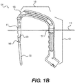
- FIGS. 1A and 1B illustrate perspective and side views, respectively, of one embodiment of a system 101 for implanting an intramedullary nail 109.
- the system 101 includes an insertion tool 103 that has a coupling portion 105 and a handle portion 107.
- the coupling portion 105 and the handle portion 107 can be separate parts that are removably joined together, while in other embodiments the coupling portion 105 and the handle portion 107 can be different regions of a single, integrally formed component.
- the coupling portion 105 releasably engages or couples to the proximal portion 111 of the nail 109.
- the free end of the coupling portion 105 can be provided with a snap-fit design to temporarily retain a portion of the intramedullary nail 109 prior to insertion of a fixation device 119 therethrough.
- a snap-fit design to temporarily retain a portion of the intramedullary nail 109 prior to insertion of a fixation device 119 therethrough.
- the handle portion 107 may include one or more openings 127, 129 configured to receive one or more guide wires 113, 115.
- the system 101 may include first and second guide wires 113, 115 as well as an optional guide sheath 117 through which the fixation device 119 may pass (e.g., the fixation device 119 can be inserted using the driver 121).
- the first and second guide wires 113, 115 may pass on opposing sides of both the nail 109 and the fixation device 119 (e.g. on posterior and anterior sides).
- the illustrated embodiment shows two guide wires, in other embodiments a single guide wire and corresponding guide wire hole may be used. In still other embodiments, three or more guide wires may be used. Additionally, the position and orientation of the guide wire holes can vary in different embodiments, for example being disposed more proximally or more distally along the insertion tool, etc.
- the insertion tool 103 allows the user to place one or more guide wires 113, 115.
- the guide wires 113, 155 are positioned both anterior and posterior to the nail 109.
- the guide wires 113, 115 may be positioned in this manner to prevent the distal fragments of the bone (e.g., distal fragments of the femoral head and neck) from rotating about the axis of the fixation device 119 when the fixation device 119 is advanced through the nail 109 and into the bone during the procedure.
- the handle portion 107 of the insertion tool 103 may include two guide wire receiving features such as holes 127, 129 on the opposing sides of the tool 103 that allow guide wires 113, 115 to pass through the respective holes.
- the guide wires 113, 115 are passed through the soft tissue and into the bone to help stabilize the insertion tool 103.
- the insertion tool 103 may not require any other instruments to guide the wires 113, 115 into the patient.
- the insertion tool 103 can achieve stability by resisting both rotational movement about the axis of the nail 109 as well as axial translation along the axis of the nail 109.
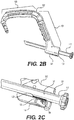
- FIGS. 2A-2C illustrate various views of the insertion tool 103 of the system 101 shown in FIGS. 1A and 1B .
- FIG. 2A is a partially exploded perspective view of the insertion tool 103 adjacent to the guide sheath 117
- FIG. 2B is a perspective view of the insertion tool 103 with the guide sheath 117 partially inserted therein
- FIG. 2C is an enlarged partial cross-sectional view of the engagement between the guide sheath 117 and the insertion tool 103.
- the guide sheath 117 can be removably inserted through a guide sheath receiving feature such as a hole 131 formed in the handle portion 107 of the insertion tool 103.
- the guide sheath hole 131 defines an axis that intersects with a first aperture 123 in the nail 109.
- the guide sheath 117 can be positioned through the guide sheath hole 131 such that it substantially aligns with the first aperture 123 in the nail 109, which is configured to receive fixation device 119 aimed at the calcar region of the bone.
- the guide sheath 117 can include a first retention member 133 on an outer surface of the guide sheath 117.
- the first retention member 133 can include, for example, ridged teeth, protrusions, or other such surface configured to engage with a corresponding second retention member 135 disposed within the guide sheath hole 131.
- the second retention member 135 can likewise include one or more ridges or protrusions. Together the first and second retention members 133, 135 form a retention mechanism 137 that allows the guide sheath 117 to be ratcheted towards the intramedullary nail 109 while restricting movement of the guide sheath 117 away from the intramedullary nail.
- the retention release mechanism 139 can disengage the second retention member 135 from the first retention member 133 when pressed by a user.
- the retention release mechanism 139 can be a button disposed on a lower surface 141 of the handle portion 107. Positioning this retention release mechanism 139 on the lower surface 141 of the insertion handle may prevent a user from accidentally releasing the guide sheath 117 while operating the device (e.g., while grasping the handle portion 107).
- FIGS. 3A-3F illustrate one method of steps of implanting an intramedullary nail into a fractured femur 143.
- a proximal end of the femur 143 can be accessed and the medullary cavity of the femur 143 can be reamed using a bone drill and reamer 145.
- the intramedullary nail 109 is coupled to the insertion tool 103 and the intramedullary nail 109 is disposed within the reamed cavity of the femur 143.
- FIG. 3A a proximal end of the femur 143 can be accessed and the medullary cavity of the femur 143 can be reamed using a bone drill and reamer 145.
- the intramedullary nail 109 is coupled to the insertion tool 103 and the intramedullary nail 109 is disposed within the reamed cavity of the femur 143.
- first and second guide wires 113 and 115 when used, one or more of the first and second guide wires 113 and 115 may be inserted through the soft tissue, for example, along parallel trajectories on opposing sides of the nail 109.
- the guide wires 113, 115 can limit or prevent inadvertent rotation of distal fragments of the femur 143 after the nail 109 is in position.
- the proximal fixation device 119 e.g., a lag screw or other suitable bone anchor
- the guide wires 113, 115 are retracted and in FIG.
- the distal fixation device 147 can additionally be inserted through the distal aperture 125 in the nail 109.
- the distal device 147 can be positioned using the guide sheath 117, which is positioned through another opening in the handle portion 107, such that the sheath 1117 is aligned with the distal opening 125 in the nail 109.
- the insertion tool 103 is disengaged from the nail 109, which is now secured in place via the proximal fixation device 119 and the distal fixation device 147.
- the nail 109 may extend along a portion of the length of femur 143. It is also contemplated, however, that the nail 109 may be of different sizes and shapes, for example, of longer lengths and/or different diameters to accommodate different anatomies and fractures.
- FIGS. 4A-4D illustrate another embodiment of an intramedullary nail 201, similar to intramedullary nail 109, with the addition of a cross-locking feature for proximal locking of the nail 201.
- Intramedullary nail 201 may include any of the features described above with respect to intramedullary nail 109.
- Intramedullary nail 201 may further include two interlocking proximal fixation devices 203, 205 (e.g., bone anchors, fasteners, or screws), for example, by providing converging and diverging purchase, along with bony fixation in the calcar of the femur 229, which is the strongest portion of the hip bone. Accordingly, the risk of failure due to cutout and/or rotation may be reduced.
- interlocking proximal fixation devices 203, 205 e.g., bone anchors, fasteners, or screws
- FIGS 4A-4D show side, side cross-sectional, and two perspective views, respectively, of the intramedullary nail 201 adjacent to a first fixation device 203.
- FIGS. 5A-5D illustrate side, side cross-sectional, and two perspective views, respectively, of the first, proximal fixation device 203 inserted through the intramedullary nail 201.
- FIGS. 6A-6D illustrate side, side cross-sectional, and two perspective views, respectively, of the system with a second, cross-locking fixation device 205 adjacent to the intramedullary nail 201 with the first fixation device 203 inserted therein.
- FIGS. 7A-7D illustrate side, side cross-sectional, and two perspective views, respectively, of the system with the second fixation device 205 inserted through both the intramedullary nail 201 and the first fixation device 203, thereby creating a cross-locking feature for proximal locking of the nail 201.
- the intramedullary nail 201 is configured to receive both the first and second fixation devices 203 and 205 therein.
- the intramedullary nail 201 includes an elongated body 207 having first and second apertures 209 and 211 formed therethrough in a proximal region 213, as well as a third aperture 215 formed in a distal region 217.
- the first aperture 209 can be sized and configured to receive the first fixation device 203 therethrough and the second aperture 211 can be sized and configured to receive the second fixation device 205 therethrough.
- the first fixation device 203 may be the same or similar to the proximal fixation device 119, described herein, and may include a bone screw or anchor configured for proximal locking of the nail 201.
- the first fixation device 203 may be a calcar screw or anchor configured to be aimed at a calcar region of the proximal humerus.
- the calcar screw 203 may have a threaded portion at its distal tip and a non-threaded portion along a substantial length of the screw 203.
- the calcar screw 203 may include traditional polyaxial or fixed angle calcar screws and anchors known in the art.
- the second fixation device 205 may also include a bone screw or anchor configured for proximal locking of the nail 201.
- This bone anchor or screw 205 may be substantially smaller in length and diameter relative to the calcar screw 203.
- the bone anchor or screw 205 is substantially sized and configured to be positioned through second opening 211 in the proximal end of the nail 201 and into a channel 219 in the first fixation device 203.
- the second device 205 is configured to interlock with the first fixation device 203, for example, enhanced purchase and bony fixation to the bone.
- the fixation device 205 may be configured to pass through a slot or channel 219 formed in the first fixation device 203. This interlocking feature of the first and second fixation devices 203, 205 can prevent cutout and rotation by providing converging and diverging purchase. In the case of a femur, this can also provide bony fixation in the calcar.
- the elongated slot 219 in the first fixation device 203 allows for controlled collapse, which leverages the natural compression between fragments from weight bearing or ligamentotaxis. Limited collapse is controlled by the length of the slot 219 to prevent the uncontrolled and excessive shortening of the femoral neck.
- the first fixation device 203 may include distal threads 221 and a proximal drive interface 223 configured to engage with a driver (not shown).
- the second fixation device 205 may have a narrower diameter than the first fixation device 203 such that the second fixation device 205 can pass through the slot 219 in the first fixation device 203.
- the second fixation device 205 may also include distal threads 225 and a proximal drive interface 227 configured to engage with a driver (not shown).
- the slot 219 can be disposed in the mid-shaft of the first fixation device 203 and may be sized and configured to allow the second fixation device 205 to pass therethrough.
- the slot 219 may be longer than necessary to allow translation of the first fixation device 203 after the second fixation device 205 is in place.
- the slot 219 may be strong enough to prevent rotation of the first fixation device 203 after the second fixation device 205 is in position.
- the slot 219 may have beveled proximal and distal edges to maximize material in the first fixation device 203 while allowing proximal and distal clearance of the second fixation device 205.
- the slot 219, in the first fixation device 203 may be symmetric to allow positioning of the second fixation device 205 in 180° increments, for example.
- a locking device 230 such as a set screw or washer, may be used to lock the first and/or the second fixation devices 203, 205 into position.
- the locking device 230 may be threaded through a hollow interior portion of the nail 201.
- the locking device 230 may have external threads, which are sized and configured to correspond to mating internal threads along the hollow interior portion of the nail 201.
- the interlocking fixation devices 203, 205 can be used selectively.
- the threaded locking device 230 may be threaded to engage the second fixation device 205; alternatively, the threaded locking device 230 may be threaded further down to lock the first fixation device 203, for example, if the second fixation device 205 is not used. This allows users the choice of a traditional or interlocking construct intraoperatively.
- An insertion tool 103 for implanting the system including the nail 201 and the interlocking first and second fixation devices 203 and 205 can be substantially similar to the system 101 described above with respect to FIGS. 1A-2C , except that an additional guide sheath hole may be formed in the handle portion 107 to accommodate a guide sheath along an appropriate trajectory to insert the second fixation device 205 through the second aperture 211 in the nail 201 and into engagement with the first fixation device 203.
- FIGS. 8A-8C illustrate one method of steps of implanting an intramedullary nail 201 with interlocking fixation devices 203, 205 into a fractured femur 229.
- the nail 201 has been inserted into a reamed medullary cavity of the femur 229 and the first fixation device 203 has been inserted through the first aperture 209 in the nail 201, similar to the technique described above with respect to FIGS. 3A-3D .
- a distal fixation device 231 can be inserted through the third aperture 215 in the nail 201, similar to the technique described above with respect to FIG. 3E .
- FIG. 8A-8C illustrate one method of steps of implanting an intramedullary nail 201 with interlocking fixation devices 203, 205 into a fractured femur 229.
- FIG. 8A the nail 201 has been inserted into a reamed medullary cavity of the femur 229 and the first fixation device 203 has been inserted through
- the second fixation device 205 is inserted through the second aperture 211 in the nail 201 and through the slot 219 in the first fixation device 203.
- these intersecting first and second fixation devices 203, 205 provide additional purchase in the head and neck region of the femur 229, and in particular the second fixation device 205 can provide bony fixation in the calcar. Accordingly, the interlocking first and second fixation devices 203, 205 can provide for improved stability and protection against common modes of intramedullary nail implant failure.
- FIGS. 9A-9N illustrate another example of an intramedullary nail 309, which may comprise a generally elongate body extending from a first, distal portion or end 310 to a second, proximal portion or end 311.
- the elongate body may be in the form of an elongate tubular rod configured to extend longitudinally within the intramedullary canal of a fractured bone.
- the elongate rod may be hollow or may be solid along its length.
- the elongate body may be substantially straight along a longitudinal axis of the nail 309 or may comprise one or more curves or bends to conform to the anatomical shape of the intramedullary canal.
- the nail 309 may be utilized in a piriformis fossa entry and the curvature may be provided in the AP (anteroposterior) direction. This curvature allows the nail 309 to be used either antegrade ( FIG. 9A ) or retrograde ( FIG. 9D ), as well as in the right leg or left leg.
- the nail 309' has curvature in the AP direction as well as a bend in the ML (medial-lateral) direction to facilitate entry at the tip of the greater trochanter.
- the nails 309 and 309' are the same unless otherwise described.
- the cross-section of the nail 309, taken at a right angle to a central longitudinal axis of the intramedullary nail 309 may be circular, oval, elliptical, or of any other suitable cross-dimensional shape.
- the radius of curvature of the nail 309 may change depending on the length of the nail 309 so that the curvature can match the anatomical curvature of the femur into which the nail 309 is being inserted. Often-times, in longer femurs (taller patients), the curvature has too small a radius, and surgeons struggle to insert the nail without causing bone damage.
- the method of radius planning based on displacement described herein reduces the likelihood of a problem by offering a more anatomically correct (larger) radius.
- the femur endpoints may be in a vertical line.
- the AP radius of curvature can be calculated using tangent circles if a valid starting point is assumed, for example, a nail length L of mm having a radius R.
- each tangent circle will have a radius R.
- Drawing a right triangle from the center C of the tangent circle, with R as the hypotenuse and 1 ⁇ 2 the nail length L as one leg of the triangle, the other leg will have a length z . Due to the curvature, the point where the legs 1/2L and z meet will be spaced a distance y from the tangent point T.
- R y /2 + L 2 /8 y .
- the constant y can be calculated.
- the radius R of curvature for each length L can be found.
- the distal end 310 of the nail 309 may include one or more distal openings 312-318 configured to receive one or more bone anchors, fasteners, or distal fixation devices 330, 332 that extend transversely through the distal end 310 of the intramedullary nail 309, and are thereby configured to secure the distal end 310 of the nail 309 within the canal.
- the distal fixation devices 330, 332 may include a bone screw or anchor configured for distal locking of the nail 309 and also reconstruction.
- the distal fixation device 330, 332 may include traditional polyaxial or fixed angle locking bone screws and anchors known in the art.
- the distal openings include an AP locking slot 312 and an AP locking opening 314.
- the openings also include a pair of ML locking openings 313, 315 and an ML locking slot 317.
- the AP and ML locking slots 312, 317 facilitate relative movement between the nail 309 and the locking screw 330 in the event compression or the like is applied during installation.
- the distal openings also include a pair of oblique openings 316, 318 configured to receive and guide reconstruction screws 332. As illustrated in FIG. 9J , each of the oblique openings 316, 318 is at an angle ⁇ 1 , ⁇ 2 relative to the axis of the nail 309.
- the angles ⁇ 1 , ⁇ 2 are in the range of 45° - 60°, and in the illustrated embodiment, are each 50°. It is preferred that the angles ⁇ 1 , ⁇ 2 are equal to one another such that the oblique openings 316, 318 are mirror images of one another, thereby allowing the nail 309 to be utilized in both right and left legs.
- the distal oblique openings 316, 318 all surgeons to lock distal screws at an angle or approach a distal fragment from a more proximal screw entry point. This configuration could be useful for treatment of periarticular fractures and condylar splits. Additionally, the oblique distal openings 316, 318 allow surgeons to access condylar fractures without risking soft tissue damage near the knee or hip joint upon entry.
- the proximal end 311 includes one or more proximal openings 123 configured to receive one or more bone anchors or fasteners 330, 332 that extend transversely through the proximal end 311 of the intramedullary nail 309, and are thereby configured to secure the proximal end 311 of the nail 309 within the canal and also reconstruction.
- the proximal fixation devices 330, 332 may include a bone screw or anchor.
- the fixation device 330 may be a locking screw and the fixation device 332 may be a calcar screw or anchor configured to be aimed at a calcar region of the proximal humerus, which may constitute the best quality bone in the region.
- the proximal openings may include a pair of ML openings 321, 323 and an ML slot 325.
- the ML openings 321, 323 and the ML slot 325 are configured to receive the locking screws 330.
- the ML locking slot 325 facilitates relative movement between the nail 309 and the locking screw 330 in the event compression or the like is applied during installation.
- the oblique angle ⁇ 1 may be about 100-150°, 110-140°, or about 120-135° relative to the nail 309 while the angle ⁇ 2 is about 30-80°, 40-70° or 45-60°.
- the proximal oblique openings 322, 324, 326 and 327 are also aligned so that they will function the same in either the right or left leg.
- the angles ⁇ 1 1 , ⁇ 3 are equal and the angles ⁇ 1 2 , ⁇ 4 are equal, however, such is not required.
- the openings whose axes are mirror images of one another are also offset in the AP plane from the sagittal plane, one by an ⁇ 1 in the anterior and the other by an angle ⁇ 2 in the anterior.
- the opening 322 is offset by ⁇ 1 while the opening 324 is offset ⁇ 2 .
- the opening 326 is offset by ⁇ 3 while the opening 327 is offset ⁇ 4 .
- the larger offset ⁇ 2 , ⁇ 4 is twice as large as the corresponding offset ⁇ 2 , ⁇ 4 . This creates room for the screw 330 to pass posteriorly to these two reconstruction screws 322 to make a fixed angle construct.
- the offset ⁇ 1 of opening 322 is equal to the offset ⁇ 4 of opening 327 while the offset ⁇ 2 of opening 324 is equal to the offset ⁇ 3 of opening 326.
- the nail 309 provides a hybrid antegrade/retrograde and left/right nail. Such a nail 309 is advantageous to hospitals and surgeons because it reduces stock and simplifies surgical planning.
- the bi-directional proximal oblique openings 322, 324, 326, 327 provide a variety of options for proximal femur fracture fixation, as well as a more stable construct. Additionally, the arrangement of the proximal openings 321-327 allows for a fixed-angle construct created by the screws 330, 332. The design further provides for three screws to be secured into the femoral neck. This fixed-angle construct provides more biomechanical stability than the traditional two screw configurations.
- the nail 309 of the present embodiment has an opening 334 at the proximal end 311.
- a shoulder 335 within the opening 334 defines a circumferential slot 336 on the inside diameter of the proximal portion 311 of the nail 309. This configuration takes up less space at the proximal end 311 of the nail 309 than a typical threaded connection, thereby freeing up space for more proximally located locking holes.
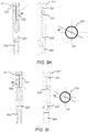
- the insertion tool 350 includes an expanding collet 370 and connecting bolt 354.
- An alignment tip 360 which connects within a through passage 353 in the aiming arm 352 of the insertion tool 350, is configured to align the bolt 354 with the expanding collet 370.
- the alignment tip 360 includes a hollow body 362 with a through passage 364 extending from a proximal end 361 to a distal end 363 of the body 362.
- the proximal end 361 of the body 362 is configured to be received into the through passage 353 of the aiming arm 362 with a press fit, however, other connecting mechanisms may be utilized.
- a shoulder 368 extends radially from the body 362 and engages the aiming arm 352 when fully inserted, as illustrated in FIGS. 11D and 11E .
- the distal end 363 of the body 362 has a recessed portion 366 configured to be received into the opening 334 in the proximal end of the nail 309.
- the expanding collet 370 includes a hollow body 372 with a through passage 374 extending from a proximal end 371 to a distal end 373 of the body 372.
- the distal end 373 has a radially outwardly extending collar 376, tabs, projections or the like.
- the collar 376 is configured to be received within the circumferential slot 336 in the proximal end 311 of the nail 309.
- Axial slots 375 extend from the distal end 373 of the body 372 and allow the distal end of the body 373 to compress radially inwardly, thereby allowing the collar 376 to pass through the alignment tip through passage 364 and the shoulder 335 within the proximal end 311 of the nail 309.
- An external shoulder 377 on the collet 370 contacts an internal shoulder 367 on the alignment tip 360 to limit the range of motion of the collet 370 relative to the alignment tip 360. Once the collar 376 is past the shoulder 335, the collar 376 is free to expand radially outwardly.
- the distal end 373 of the collet body 372 includes internal threads 378 configured for engagement with the threads 355 of the connecting bolt 354.
- the connecting bolt 354 then drives through the through passage 374 of the expandable collet 374 and engages the threads 378. As the connecting bolt 354 is threaded with the threads 378, it pushes the collar 376 outwardly to its major diameter and further drives the collar 376 into the circumferential slot 336 within the nail 309. In addition, when the bottom side of the head 356 of the bolt 354 makes contact with the top of the alignment tip 360, it allows for compression across the proximal nail 309, thus compressing any spacing in the connection.
- the assembly allows for quick, easy, and rigid connection of the nail 309 to the aiming arm 352. It is noted that any of the intramedullary nails described herein may include an internal circumferential slot and be connected to an insertion tool or the like utilizing an expanding collet as described.
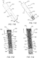
- a self-retaining screw 400 and driver 430 assembly will be described. Screws are often affixed to drivers on the back table by a scrub tech or nurse and then they are handed to the surgeon who places the screw where it is needed. Between the back table, and the final seating of the screw into the bone, many actions can dislodge it from the driver, thus rendering it non-sterile, for example, when it hits the operating room floor. To minimize the likelihood of dislodging, the self-retaining nail locking screw 400 has features which achieve a more secure connection.
- the screw 400 includes a shaft 402 extending from a distal tip 404 to a proximal head 406.
- the shaft 402 includes a two thread 403, 405 start which provides for easier advancement.
- the head 406 defines a proximal torque bore 410 and a threaded bore 416 distally thereof.
- the torque bore 410 and the threaded bore 416 are in communication with one another and preferably coaxial.
- the torque bore 410 has a configuration with engaging surfaces to engage a complimentary torque tool.
- the torque bore 410 has a hexalobe configuration with a plurality of lobal recesses 412 extending radially from the central opening.
- the lobal recesses 412 define a maximum diameter D while the central opening defines a smaller diameter d.
- the lobal recesses 412 are configured to receive complementary lobes 436 on a driving tool head 430, as will be described in more detail below.
- the threaded bore 416 defines a plurality of internal threads 417 which are configured to be engaged by a threaded rod (not shown) which tightens into the threaded bore 416 at the bottom of the torque bore 410.
- the combination of a torque bore 410 and a threaded bore 416 allows for secure delivery of the screw 400 utilizing the threaded rod and thereafter additional tightening of the screw 400, if needed, utilizing a torque driver engaged with the torque bore 410.
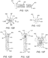
- the torque driver head 430 illustrated therein has a taper in order to give it a stab and grab retaining feature on its own.
- the torque driver head 430 includes a proximal body 432 and a distal shaft 434 extending therefrom.
- the proximal body 432 and shaft 434 are preferably a unitary structure extending from a proximal end 431 to a distal end 433.
- a plurality of lobes 436 extend radially from the shaft 434 and have a complementary configuration to the lobal recesses 412 in the torque bore 410 of the screw 400.
- the lobes 436 taper, narrowing moving in the distal direction.
- the taper is generally constant over a first length E 1 and then more pronounced at the distal end 433 over the length E 2 .
- the lobes 436 define a larger maximum diameter F 1 in the proximate portion of the shaft 434 (see FIG. 12J ) and a smaller maximum diameter F 2 in the distal portion of the shaft 343 (see FIG. 12K ).
- the larger diameter F 1 is preferably larger than the maximum diameter D of the lobal recesses 412 and the smaller diameter F 2 is preferably smaller than the maximum diameter D of the lobal recesses 412, i.e. F 1 >D>F 2 .
- the distal end 433 of the torque driver head 430 moves easily into the torque bore 410, however, as the torque driver head 430 is inserted further, the lobes 436 engage the lobe recesses 412 in a friction fit, providing the stab and grab retaining feature. In some instances, this feature may provide sufficient secure connection without the need to utilize the threaded rod and threaded bore 416.
- FIGS. 13A-13F a headless version of the screw 400' will be described.
- a surgeon may desire to have as low of a head profile on a screw as possible.
- a fracture occurs near the joint space, it is often necessary for a surgeon to place screws through the articular surface.
- the locking screw used does not impinge any motion of the bones or soft tissues in that region.
- a headless screw may also be desired in areas where the soft tissue above the bone is very thin, so prominent screw heads may be felt or even seen by the patient post-op (e.g., in the proximal tibia).
- the headless screw 400' is similar to the screw of the previous embodiment and includes a shaft 402 extending from a distal tip 404 to a proximal head 406'.
- the shaft 402 includes a two thread 403, 405 start which provides for easier advancement.
- the screw 400' may have a single thread start or any other suitable configuration.
- the head 406' defines a proximal torque bore 410 and a threaded bore 416 distally thereof.
- the torque bore 410 has a configuration with engaging surfaces to engage a complimentary torque tool and the threaded bore 416 defines a plurality of internal threads 417.
- the head 406' of the present embodiment has a plurality of external threads 407.
- the threads 407 may have a four start thread that is half the pitch of the shaft thread.
- the threads 407 allow the head 406' to be sunk beneath the surface of the bone.
- the headless screw 400' provides a unique offering of a headless option that still acts the same as a standard locking screw.
- an intramedullary nail system includes an intramedullary nail in combination with at least one headless screw or fastener.
- the intramedullary nail may include intramedullary nails 109, 201, 309, 500 described herein or any other intramedullary nails generally known or hereinafter developed.
- the headless screw or fastener is intended to encompass a screw or fastener, which is blind such that the screw is fully threaded and has no head projecting past a major diameter of the screw thread and/or may encompass a screw or fastener having a head portion where the thread extends all the way to the head (e.g., a threaded head).
- the headless screw may include headless screw 400' described herein or any other headless screw generally known or hereinafter developed.
- the intramedullary nail 109, 201, 309, 500 is used in combination with at least one headless screw 400' or headless fastener.
- the headless screw 400' or other headless fastener may be positioned through the body of the nail 109, 201, 309, 500 such that the shaft 402 resides within one or more openings in the nail 109, 201, 309, 500.
- the shaft 402 of the headless screw 400' may be configured to mate with the intramedullary nail 109, 201, 309, 500 in a locking (e.g., threaded mating) or non-locking fashion.
- the threaded head 406' of the headless screw 400' may be positioned such that the head 406' is positioned at or near the outer surface of the bone, for example, as best seen in FIG. 9A .
- the intramedullary system may be substantially unnoticeable to a patient.
- traditional headed screws sometimes patients complain that they are able to feel the screw or the screw head protrudes from the surgical site causing irritation or pain to the patient. Accordingly, it may be suitable for one or more headless screws or fasteners to be used when securing the distal and/or proximal ends of the intramedullary nail, thereby resulting in superior patient outcomes.
- the nail 450 is provided with one or more threaded holes 454 along the elongate body 452 of the nail 450.
- the threaded hole 454 includes threads 453, 455 with a two start thread. In the illustrated embodiment, the threads 453, 455 provide a two start 60-degree machine thread. The threads 453, 455 will have the same pitch as the threads 403, 405 of the screw 400.
- the screw shaft 402 also has a two start thread for easy advancement.
- the threaded two start hole 454 in the nail 450 itself is an advantage over current interference holes because it is easy to manufacture, and requires no additional steps or special techniques on the part of the surgeon.
- a washer 470 configured to provide greater compression on the screw will be described.
- the screw and nail may not provide sufficient interference.
- surgeons often require a screw which interfaces with the nail itself.
- the near cortical wall is not stable, which is the case in a number of complex femur fractures, even an interference fit screw will not get any purchase in the near cortex, and therefore the fixation will be unstable.
- the washer 470 may be provided as an option for use with a screw and nail assembly if the conditions present the need for such.
- the washer 470 includes a hollow body 472 with a through passage 474 extending from a proximal end 471 of the body 472 to a distal end 473 of the body 472.
- the distal end 473 of the body 472 includes a plurality of cutouts 475 between distal tips 476. Each cutout 475 is approximately 90° such that each pair of opposed cutouts 475 is coaxial thereby allowing an outer diameter of the nail.
- the washer 470 fits over the major diameter of the screw and sits flush with the underside of the head. It may be inserted through a tissue protection sleeve along with the screw and driver.
- the screw continues to spin while the washer 470 grips the side of the nail. This allows the screw to get compression on the far side of the nail and hold the screw/washer construct firmly to the side of the nail. This provides a rigid fixation method when the cortical bone is not strong enough to do so.
- the washer 470 thereby expands the indications for which the nail can be used.
- FIGS. 16A-16D a first tibial intramedullary nail 500 will be described. It is recognized that the features of the nail 500 are not limited to use in a tibial nail and may be incorporated into other intramedullary nails.
- the intramedullary nail 500 generally comprises an elongate body 502 extending from a first, distal portion or end 203 to a second, proximal portion or end 501.
- the elongate body 502 may be in the form of an elongate tubular rod configured to extend longitudinally within the intramedullary canal of a fractured bone.
- the elongate rod may be hollow or may be solid along its length.
- the elongate body may be substantially straight along a longitudinal axis of the nail 500 or may comprise one or more curves or bends to conform to the anatomical shape of the intramedullary canal.
- the nail 500 is utilized in a tibia and the proximal end has a bend ⁇ relative to the shaft has a bend while the distal end has a bend ⁇ relative to the shaft.
- the bend ⁇ is approximately 10° while the distal end bend ⁇ is approximately 3°.
- the bends ⁇ and ⁇ are not limited to the described angles and may have larger or smaller bends depending on the anatomy of the bone.
- the distal end 503 of the tibial nail 500 contains four openings 510-513.
- the openings 510, 512 are oriented in the ML direction and the openings 511, 513 are oriented in the AP direction.
- the ML opening 510 and the AP opening 511 each include a 2 start thread 514 used to create a fixed angle construct with the locking screw, similar to that described above with respect to FIG. 14C .
- Fixed angle constructs are used to treat highly unstable fractures.
- the ML opening 510 is replaced with a combined oblique locking opening 520, with first and second openings 521, 522 each at an oblique angle, for example, at 30° off the sagittal plane.
- the combined oblique locking opening 520 allows the surgeon to insert locking screws 530 in two different orientations, thereby creating an alternative fixed angle construct.
- FIG. 16H another alternative distal end 503" of the nail 500" illustrates additional features which may be utilized to create a fixed angle construct.
- the AP opening 511' is defined as a broached hole while the AP opening 513' is defined as a threaded hole.
- the fixed angle construct is created by inserting a locking screw through the threaded or broached hole. The locking screw thread engages with the threads or broached features to stabilize the fracture by limiting the movement of the screw 530 relative to the nail 503".
- the proximal end 501 of the tibial nail 500 contains openings 515-518, including a pair of proximal oblique openings 515, an AP oblique opening 516, a proximal ML slot 517 and a proximal ML opening 517.
- the proximal oblique openings 515 are similar to those describe above with respect to the embodiment illustrated in FIG. 9A .
- the AP oblique opening 516 contains a 2 start thread 519 used to create a fixed angle construct with a locking screw.
- the proximal ML slot 517 is used for compression of fractures and static/dynamic locking modes.
- FIGS. 17A-17K illustrate various features of illustrative tibia nails 500, tools, systems and methods of inserting the tibia nails 500 will be described with reference to FIGS. 17A-17K .
- the tibial nail 500 is inserted into the medullary canal through an incision at the entry site.
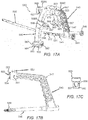
- FIG. 17A illustrates an illustrative embodiment of a system 530 for implanting an intramedullary nail 500 utilizing the infra-patellar approach.
- the infra-patellar approach is the industry standard approach for insertion of the tibial nail 500. This approach is typically performed with the leg in the hyper-flexed (HF) position.
- the tibial nail 500 is inserted directly through the incision into the tibial canal.
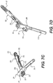
- the system 530 includes an insertion tool 540 and an aiming guide 560.
- the insertion tool 540 includes a coupling portion 545 and a handle portion 547.
- the coupling portion 545 and the handle portion 547 can be separate parts that are removably joined together, while in other embodiments the coupling portion 545 and the handle portion 547 can be different regions of a single, integrally formed component.
- the handle portion 547 is preferably rigid, for example, made from stainless steel and also has provisions to attach an impaction shaft 546 and compression bolt 544.
- the coupling portion 545 has a connection portion 548 configured to releasably engage or couple to the proximal portion 501 of the nail 500.
- the connection portion 548 includes a threaded connector.
- other coupling mechanisms may be employed.
- the handle portion 547 includes a connection assembly 550 for releasably attaching the handle portion 547 to the aiming guide 560.
- the connection assembly 550 includes a body 551 with two bores 552, 554 defined therein.
- a connection button 553 extends into one of the bores 552.
- the connection button 553 is biased to a connected position as illustrated in FIG. 17B .
- the connection button 553 has an engagement portion 556 within the bore 552 configured to engage a slot 573 on a connection post 572 of the aiming guide, as will be described in more detail hereinafter.
- the engagement portion 556 includes a plate with a smaller diameter opening 557. To disengage the engagement portion 556, the button 553 is depressed such that the larger diameter opening 558 aligns with the connection post 572.
- other connection mechanisms may be employed.
- the tibial nail aiming guide 560 is used to install locking screws into the tibial nail 500.
- the aiming guide 560 sets the trajectory of the locking screws to interface with the proximal openings 515-518 of the nail 500.
- the aiming guide 560 is made from a radiolucent material.
- the aiming guide 560 includes an arcuate body 562 which extends between opposed end support blocks 564. Each end support block 564 defines a hole opening 563, which aligns with the ML opening 518, and a slot opening 565, which aligns with the ML slot 517.
- a plurality of intermediate support blocks 568A-C extending from the body 562.
- the support block 568A includes a hole opening 569 which is aligned with the AP oblique opening 516.
- the support blocks 568B and 568C each include a hole opening 569 which is aligned with a respective oblique opening 515.
- the openings 563, 565, and 569 are configured to support respective guide sheaths 580 similar to the guide sheaths 117 described above.
- the sheaths 580 are used to protect the soft tissue during the drilling process.
- the sheaths 580 accept drill sleeves and trocars of various sizes.
- the guide sheaths 580 and blocks 564, 568A-C may have retention members similar to those described above, with each block 564, 568A-C having a respective release mechanism 567.
- the aiming guide 560 also includes a connection assembly 570 configured to mate with the connection assembly 570 on the insertion handle 540.
- the connection assembly 570 includes a body 571 with a pair of connection posts 572, 574 extending therefrom which are configured to be received in the bores 552, 554 of the connection assembly 550.
- the connection post 572 includes a slot 573 configured to be selectively engaged by the engagement portion 556 of the connection button 553.
- the connector assembly 570 is a rigid structure and may be made from, for example, metal.
- the system 530 provides an insertion handle 547 with reliable and convenient connection assembly for attaching the aiming guide 560.
- a push button connection and release system allows tool free connection and disconnection of the aiming guide 560.
- the insertion handle 547 also contain an external compression bolt 544 used to apply pressure the locking screw in the dynamic position to compress a fracture gap.
- the aiming guide 560 utilizes a push button release mechanism 567 that locks the soft tissue sheaths 580 in place.
- the release mechanism 567 allows insertion of the soft tissue sheath 580 but prevents it from backing out. This feature helps to maintain the position of the soft tissue sheaths 580 for accurate screw length measurements and facilitates drilling and screw insertion.
- the aiming guide 560 is designed with extended sheath guides 580 for improved aiming accuracy.
- the supra-patellar approach uses a tibia entry point above the knee.
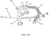
- a system 530' for use with the supra-patellar approach will be described with reference to FIGS. 17F-17L .
- the system 530' is substantially as in the previous embodiment but further includes a cannula assembly 590.
- the cannula assembly 590 protects the articular surface of the knee during the nail insertion process.
- the cannula assembly 590 also protects the articular surface of the knee during reaming.
- the reaming is performed through a drill guide 610 in the cannula 592 of the cannula assembly 590. Thereafter, the drill guide 610 is removed and nail 500 insertion is performed through the cannula 592 into the entry incision.
- the cannula assembly 590 includes a flexible cannula 592 and a rigid handle 596.
- the cannula 592 has a through passage 594 which is aligned with an opening 599 in the handle 596 to define a continuous passage.
- the flexible cannula 592 material is over-molded onto the rigid plastic handle 596.
- a pair of tibia guide slots 595 extend through the handle 596 and along the sides of the cannula 592.
- Transverse femur guide holes 597 extend through the handle 596. As shown in FIG. 17H , the guide slots 595 and guide holes 597 guide fixation pins 600, 602 into the tibia 144 or femur 143.
- the cannula assembly 590 is inserted through an incision in the skin and is the working portal through which the surgeon can perform reaming, drilling, and nail insertion.
- the guide slots 595 and holes 597 allow the surgeon to fix the cannula 592 in place during the procedure.
- the guide slots 595 and holes 597 allow the cannula to be fixed to the femur 143 or tibia 144 with converging pins 602, 600 depending on surgeon preference.
- the cannula 592 is reversible and can be used on either side of the patient. Referring to FIG. 17I , the cannula assembly 590 is designed to accept a metal drill sleeve 610 and round trocar 612.
- connection point 603 on the cannula handle 596 that accepts the connector 611 on the metal drill sleeve 610.
- the cannula 592 is tapered for easy removal of the drill sleeve 610.
- the soft, flexible cannula 592 is anatomically shaped to fit between the femoral condyles and minimize damage to the articular surface.
- the cannula assembly 590' in accordance with another illustrative embodiment will be described.
- the cannula assembly 590' is similar to the previous embodiment and includes a flexible cannula 592' extending from a rigid hub 596'.
- the rigid hub 596' includes legs 593 extending from each side of the cannula 592'.
- Each leg 593 of the hub 596' defines a respective tibia fixation hole 595' and a series of femur pin holes 597'.
- the two tibia fixation holes 595' are designed to accept k wire 600 for fixation to the tibia.
- the wires 600 can be convergent or parallel.
- the femur pin holes 597' are for femur fixation using half pins 602.
- the cannula assembly 590' is designed to accept a metal drill sleeve 610 and round trocar 612.
- the invention could be inter alia defined by the following aspects:
Landscapes
- Health & Medical Sciences (AREA)
- Orthopedic Medicine & Surgery (AREA)
- Surgery (AREA)
- Life Sciences & Earth Sciences (AREA)
- Heart & Thoracic Surgery (AREA)
- Veterinary Medicine (AREA)
- Engineering & Computer Science (AREA)
- Biomedical Technology (AREA)
- Nuclear Medicine, Radiotherapy & Molecular Imaging (AREA)
- Medical Informatics (AREA)
- Molecular Biology (AREA)
- Animal Behavior & Ethology (AREA)
- General Health & Medical Sciences (AREA)
- Public Health (AREA)
- Neurology (AREA)
- Dentistry (AREA)
- Oral & Maxillofacial Surgery (AREA)
- Surgical Instruments (AREA)
Applications Claiming Priority (2)
| Application Number | Priority Date | Filing Date | Title |
|---|---|---|---|
| US15/272,850 US10299847B2 (en) | 2016-09-22 | 2016-09-22 | Systems and methods for intramedullary nail implantation |
| US15/423,773 US10251691B2 (en) | 2016-09-22 | 2017-02-03 | Systems and methods for intramedullary nail implantation |
Publications (3)
| Publication Number | Publication Date |
|---|---|
| EP3357438A2 true EP3357438A2 (fr) | 2018-08-08 |
| EP3357438A3 EP3357438A3 (fr) | 2018-10-24 |
| EP3357438B1 EP3357438B1 (fr) | 2021-07-07 |
Family
ID=59914360
Family Applications (2)
| Application Number | Title | Priority Date | Filing Date |
|---|---|---|---|
| EP17191810.5A Withdrawn EP3298972A3 (fr) | 2016-09-22 | 2017-09-19 | Systèmes d'implantation de clous intramédullaires |
| EP18154013.9A Active EP3357438B1 (fr) | 2016-09-22 | 2018-01-30 | Systèmes d'implantation de clous intramédullaires |
Family Applications Before (1)
| Application Number | Title | Priority Date | Filing Date |
|---|---|---|---|
| EP17191810.5A Withdrawn EP3298972A3 (fr) | 2016-09-22 | 2017-09-19 | Systèmes d'implantation de clous intramédullaires |
Country Status (3)
| Country | Link |
|---|---|
| US (13) | US10299847B2 (fr) |
| EP (2) | EP3298972A3 (fr) |
| JP (3) | JP7573351B2 (fr) |
Families Citing this family (44)
| Publication number | Priority date | Publication date | Assignee | Title |
|---|---|---|---|---|
| CN107530114B (zh) * | 2015-03-25 | 2020-06-26 | 皮耶尔·乔瓦尼·门奇 | 用于治疗长骨骨折的髓内钉 |
| US11213334B2 (en) * | 2015-10-07 | 2022-01-04 | Stabiliz Orthopaedics, LLC | Bone fracture fixation device with transverse set screw and aiming guide |
| GB2544501B (en) * | 2015-11-18 | 2017-12-13 | Grampian Health Board | Variable curve jig for an intramedullary nail |
| WO2018042595A1 (fr) * | 2016-09-01 | 2018-03-08 | 株式会社オーミック | Outil de fixation de fémur |
| US11083503B2 (en) | 2016-09-22 | 2021-08-10 | Globus Medical, Inc. | Systems and methods for intramedullary nail implantation |
| US10299847B2 (en) | 2016-09-22 | 2019-05-28 | Globus Medical, Inc. | Systems and methods for intramedullary nail implantation |
| US10751096B2 (en) | 2016-09-22 | 2020-08-25 | Bala Sundararajan | Systems and methods for intramedullary nail implantation |
| US12594108B2 (en) | 2016-09-22 | 2026-04-07 | Globus Medical Inc. | Systems and methods for intramedullary nail implantation |
| US11045242B2 (en) | 2016-09-22 | 2021-06-29 | Globus Medical, Inc. | Systems and methods for intramedullary nail implantation |
| US10251682B2 (en) * | 2017-03-22 | 2019-04-09 | DePuy Synthes Products, Inc. | Distal radius nail |
| US10722269B2 (en) * | 2017-06-30 | 2020-07-28 | DePuy Synthes Products, Inc. | Variable-angle bone plate placement tool, system, and method of using the same |
| EP3691543A1 (fr) | 2017-10-06 | 2020-08-12 | Paragon 28, Inc. | Système de fixation de ligament, implants, dispositifs, et procédés d'utilisation |
| CN111447885B (zh) * | 2017-10-09 | 2023-10-20 | 精密医疗责任有限公司 | 使用锁定到环绕锚定件的钉来进行骨固定的系统和方法 |
| US11446072B2 (en) * | 2017-10-10 | 2022-09-20 | DePuy Synthes Products, Inc. | Self-retaining nail to insertion handle interface |
| US11633196B2 (en) * | 2017-12-21 | 2023-04-25 | PMSW Research Pty Ltd | Minimally invasive hip arthroplasty techniques and apparatus |
| US10932828B2 (en) * | 2018-01-25 | 2021-03-02 | Advanced Orthopaedic Solutions, Inc. | Bone nail |
| ES2735007B2 (es) * | 2018-06-11 | 2020-07-17 | Desarrollos Biomecanicos Innovasan S L | Prótesis de cadera o de hombro e instrumental de colocación. |
| CN109009378A (zh) * | 2018-08-17 | 2018-12-18 | 大博医疗科技股份有限公司 | 跟骨骨折复位固定装置 |
| JP6983204B2 (ja) * | 2018-10-08 | 2021-12-17 | グローバス メディカル インコーポレイティッド | 髄内釘埋め込みのためのシステムおよび方法 |
| US12484915B2 (en) * | 2018-10-15 | 2025-12-02 | University Of Kentucky Research Foundation | Antegrade retrograde recon femoral intramedullary nail system |
| US20200113609A1 (en) * | 2018-10-15 | 2020-04-16 | University Of Kentucky Research Foundation | Antegrade retrograde recon femoral intramedullary nail system |
| IT201900002543A1 (it) * | 2019-02-21 | 2020-08-21 | Medacta Int Sa | Dispositivo di posizionamento di uno strumento chirurgico per operazioni di artroplastica dell'anca |
| CN109907813A (zh) * | 2019-02-28 | 2019-06-21 | 创生医疗器械(中国)有限公司 | 髓内钉打入器稳定装置 |
| IT201900005180A1 (it) * | 2019-04-05 | 2020-10-05 | Enrico Paganelli | Chiodo endomidollare |
| EP3747375A1 (fr) * | 2019-06-05 | 2020-12-09 | Globus Medical, Inc. | Systèmes d'implantation de clous intramédullaires |
| JP7739267B2 (ja) | 2019-09-12 | 2025-09-16 | パラゴン28・インコーポレイテッド | 動的固定インプラントおよび使用方法 |
| US11166754B2 (en) * | 2019-09-18 | 2021-11-09 | DePuy Synthes Products, Inc. | Strike instrument for intramedullary nail |
| US11540846B2 (en) | 2019-10-22 | 2023-01-03 | DePuy Synthes Products, Inc. | Aiming device for intramedullary nails, and related systems and methods |
| US11207115B2 (en) * | 2019-11-21 | 2021-12-28 | DePuy Synthes Products, LLC | System and method of coupling an alignment guide to an intramedullary nail insertion handle |
| CN111134817B (zh) * | 2020-02-25 | 2025-01-24 | 吴丹凯 | 一种基于髓内钉系统的骨搬移装置 |
| EP4146103A1 (fr) * | 2020-05-06 | 2023-03-15 | Smith&Nephew, Inc. | Clous intramédullaires orthopédiques |
| CN113662648A (zh) * | 2020-05-15 | 2021-11-19 | 北京中安泰华科技有限公司 | 一种髓内针配套装置 |
| CN116133605A (zh) | 2020-05-29 | 2023-05-16 | 史赛克欧洲运营有限公司 | 用于髓内钉的漏斗孔 |
| KR102466883B1 (ko) * | 2020-07-09 | 2022-11-16 | 주식회사 제일메디칼코퍼레이션 | 수술용 조준기구 |
| CN113116490A (zh) * | 2021-04-13 | 2021-07-16 | 上海市第六人民医院 | 一种用于股骨颈骨折的内固定器及辅助装置 |
| CN113813036A (zh) * | 2021-08-23 | 2021-12-21 | 张英泽 | 一种股骨转子间骨折适形钉内固定系统 |
| CN113679462A (zh) * | 2021-08-30 | 2021-11-23 | 北京市春立正达医疗器械股份有限公司 | 一种防切出髓内钉 |
| CN116264982B (zh) * | 2021-12-16 | 2025-11-11 | 苏州微创脊柱创伤医疗科技有限公司 | 一种瞄准装置 |
| CN114533234B (zh) * | 2022-01-29 | 2024-03-22 | 中国人民解放军总医院 | 一种用于肱骨近端骨折的修复装置 |
| US11801077B2 (en) * | 2022-03-14 | 2023-10-31 | Orthotek, LLC. | Bone fixation system |
| US11844554B1 (en) * | 2022-07-28 | 2023-12-19 | Globus Medical, Inc. | Retrograde femoral nail system and related methods |
| CN115530957B (zh) * | 2022-09-29 | 2025-05-30 | 任晓春 | 弹性髓内针闭合取出器 |
| CN117582281B (zh) * | 2023-12-22 | 2025-07-18 | 北京大学人民医院 | 一种髋臼周围经皮置内固定加强髓内钉的体外导向架 |
| WO2025235932A2 (fr) | 2024-05-10 | 2025-11-13 | Zimmer, Inc. | Clou fémoral à multiples capacités de vis anti-rotation |
Family Cites Families (413)
| Publication number | Priority date | Publication date | Assignee | Title |
|---|---|---|---|---|
| US1105105A (en) | 1912-02-10 | 1914-07-28 | William O'n Sherman | Surgical appliance. |
| US2486303A (en) | 1948-04-29 | 1949-10-25 | Harry Herschel Leiter | Surgical appliance for bone fractures |
| DE1445692A1 (de) | 1963-03-25 | 1969-03-20 | Egyt Gyogyszervegyeszeti Gyar | Verfahren zur Herstellung von Piperazinderivaten |
| US3463148A (en) | 1966-01-20 | 1969-08-26 | Richards Mfg Co | Bone plate |
| US3695259A (en) | 1970-11-10 | 1972-10-03 | Clyde E Yost | Bone plate |
| US3716050A (en) | 1971-02-11 | 1973-02-13 | F Johnston | Olecranon plate |
| CH613858A5 (fr) | 1977-04-22 | 1979-10-31 | Straumann Inst Ag | |
| CH651192A5 (de) | 1980-11-20 | 1985-09-13 | Synthes Ag | Osteosynthetische vorrichtung und dazu passende bohrlehre. |
| FR2517536B1 (fr) | 1981-12-09 | 1986-12-12 | Zbikowski Juan | Dispositif de fixation fonctionnelle pour osteo-synthese au moyen de plaques de compression |
| CH662936A5 (de) | 1984-05-18 | 1987-11-13 | Technomed Gmk | Knochenverbindungsplatte. |
| US4667664A (en) | 1985-01-18 | 1987-05-26 | Richards Medical Company | Blind hole targeting device for orthopedic surgery |
| US4622959A (en) * | 1985-03-05 | 1986-11-18 | Marcus Randall E | Multi-use femoral intramedullary nail |
| US4683878A (en) | 1985-04-29 | 1987-08-04 | Kirschner Medical Corporation | Osteosynthetic fixation plate |
| PL147580B1 (en) | 1986-04-14 | 1989-06-30 | Plate for uniting epiphysis and diaphysis of broken bone | |
| US4776330A (en) | 1986-06-23 | 1988-10-11 | Pfizer Hospital Products Group, Inc. | Modular femoral fixation system |
| US4781183A (en) | 1986-08-27 | 1988-11-01 | American Cyanamid Company | Surgical prosthesis |
| US5167663A (en) | 1986-12-30 | 1992-12-01 | Smith & Nephew Richards Inc. | Femoral fracture device |
| US5312406A (en) | 1986-12-30 | 1994-05-17 | Smith & Nephew Richards Inc. | Method of treating an intertrochanteric fracture |
| US4966599A (en) | 1987-04-07 | 1990-10-30 | Pollock Richard A | Anatomical precontoured plating, instruments and methods |
| DE8706912U1 (de) | 1987-05-14 | 1987-08-27 | Howmedica GmbH, 2314 Schönkirchen | Kleinknochenplatte und Schrauben, insbesondere für die Versorgung von Frakturen des Schädel- und Gesichtsskeletts o. dgl. |
| DE3722853A1 (de) | 1987-07-10 | 1989-01-19 | Kernforschungsz Karlsruhe | Endoprothese fuer ein femurhueftgelenk |
| DE3722852A1 (de) | 1987-07-10 | 1989-01-19 | Kernforschungsz Karlsruhe | Implantat zur versorgung von knochenbruechen |
| US5151103A (en) | 1987-11-03 | 1992-09-29 | Synthes (U.S.A.) | Point contact bone compression plate |
| CH673762A5 (fr) | 1987-12-02 | 1990-04-12 | Synthes Ag | |
| US5176681A (en) | 1987-12-14 | 1993-01-05 | Howmedica International Inc. | Intramedullary intertrochanteric fracture fixation appliance and fitting device |
| CH674613A5 (fr) * | 1988-03-14 | 1990-06-29 | Synthes Ag | |
| EP0355411A1 (fr) * | 1988-08-10 | 1990-02-28 | Ace Medical Company | Broche intramédullaire pour stabiliser le fémur |
| US4952213A (en) | 1989-02-03 | 1990-08-28 | Boehringer Mannheim Corporation | Tibial cutting guide |
| US5034013A (en) | 1989-04-24 | 1991-07-23 | Zimmer Inc. | Intramedullary nail |
| US4978349A (en) * | 1989-08-03 | 1990-12-18 | Synthes (U.S.A.) | Fixation plate |
| US4923471A (en) | 1989-10-17 | 1990-05-08 | Timesh, Inc. | Bone fracture reduction and fixation devices with identity tags |
| IT1237496B (it) | 1989-10-26 | 1993-06-08 | Giuseppe Vrespa | Dispositivo a vite per l'ancoraggio di protesi alle ossa, metodo per l'applicazione di tale dispositivo e relativa attrezzatura |
| US5032125A (en) | 1990-02-06 | 1991-07-16 | Smith & Nephew Richards Inc. | Intramedullary hip screw |
| DE9101037U1 (de) * | 1991-01-30 | 1991-04-18 | Howmedica GmbH, 2314 Schönkirchen | Zielgerät für ein Implantat zur Versorgung trochanterer und subtrochanterer Frakturen |
| DE9114118U1 (de) | 1991-11-13 | 1992-01-02 | Howmedica GmbH, 2314 Schönkirchen | Stützmittel für die menschliche Wirbelsäule |
| DE4240277C2 (de) | 1991-12-03 | 1995-04-13 | Pennig Dietmar | Zielvorrichtung für einen der Osteosynthese dienenden Verriegelungsnagel |
| US5779706A (en) | 1992-06-15 | 1998-07-14 | Medicon Eg | Surgical system |
| US5433720A (en) | 1992-09-22 | 1995-07-18 | Orthofix S.R.L. | Centering means for holes of intramedullary nails |
| US5429640A (en) * | 1992-11-27 | 1995-07-04 | Clemson University | Intramedullary rod for fracture fixation of femoral shaft independent of ipsilateral femoral neck fracture fixation |
| US5350380A (en) * | 1993-01-15 | 1994-09-27 | Depuy Inc. | Method for securing a ligament replacement in a bone |
| US5354300A (en) | 1993-01-15 | 1994-10-11 | Depuy Inc. | Drill guide apparatus for installing a transverse pin |
| US6001099A (en) | 1998-06-08 | 1999-12-14 | Huebner; Randall J. | Bone plate with varying rigidity |
| US5364399A (en) | 1993-02-05 | 1994-11-15 | Danek Medical, Inc. | Anterior cervical plating system |
| US5423826A (en) | 1993-02-05 | 1995-06-13 | Danek Medical, Inc. | Anterior cervical plate holder/drill guide and method of use |
| USD365634S (en) | 1993-09-23 | 1995-12-26 | Timesh, Inc. | Metallic surgical grid material |
| US5468242A (en) | 1993-11-19 | 1995-11-21 | Leibinger Gmbh | Form-fitting mesh implant |
| US5578036A (en) | 1993-12-06 | 1996-11-26 | Stone; Kevin T. | Method and apparatus for fixation of bone during surgical procedures |
| US5709687A (en) | 1994-03-16 | 1998-01-20 | Pennig; Dietmar | Fixation pin for small-bone fragments |
| US5489305A (en) | 1994-10-03 | 1996-02-06 | Timesh, Inc. | Mandibular prostheses |
| US5601553A (en) | 1994-10-03 | 1997-02-11 | Synthes (U.S.A.) | Locking plate and bone screw |
| US5549610A (en) | 1994-10-31 | 1996-08-27 | Smith & Nephew Richards Inc. | Femoral intramedullary nail |
| DE4445692C2 (de) | 1994-11-17 | 1997-01-16 | Treu Instr Gmbh | Marknagel zur Hüftkompression |
| IT1271079B (it) | 1994-11-22 | 1997-05-26 | Lucio Martinotti | Retina per la chirurgia ortopedico-traumatologica |
| SE505453C2 (sv) | 1995-02-14 | 1997-09-01 | Robert J Medoff | Implanteringsbar stödplatta |
| KR100329539B1 (ko) | 1995-03-27 | 2002-11-13 | 신테스 아게 츄어 | 뼈고정판 |
| US5613971A (en) * | 1995-08-11 | 1997-03-25 | Depuy Inc. | Ratcheting tibial and femoral guide |
| DE59509247D1 (de) | 1995-09-06 | 2001-06-13 | Synthes Ag | Knochenplatte |
| US5676667A (en) | 1995-12-08 | 1997-10-14 | Hausman; Michael | Bone fixation apparatus and method |
| DE29520312U1 (de) | 1995-12-21 | 1996-02-08 | Leibinger Medizintech | Knochenschraube |
| DE19549180A1 (de) | 1995-12-30 | 1997-07-03 | Bosch Gmbh Robert | Stator für elektrische Maschine |
| US5785712A (en) | 1996-04-16 | 1998-07-28 | Terray Corporation | Reconstruction bone plate |
| US5814048A (en) | 1996-05-03 | 1998-09-29 | Sofamor Danek Properties, Inc. | Cranioplasty plates and method of installation |
| EP0909143A4 (fr) | 1996-06-14 | 2008-11-26 | Depuy Ace Medical Company | Plaque vissee pour extremites osseuses superieures |
| CA2179864C (fr) | 1996-06-25 | 2002-05-07 | Robert John Runciman | Modele de plaque vissee |
| US5718705A (en) | 1996-07-16 | 1998-02-17 | Sammarco; Giacomo J. | Internal fixation plate |
| EP0917450A1 (fr) | 1996-08-12 | 1999-05-26 | SYNTHES AG Chur | Plaque pour osteosynthese |
| US5766176A (en) | 1996-09-11 | 1998-06-16 | Walter Lorenz Surgical, Inc. | Formable mesh |
| US5690631A (en) | 1996-09-11 | 1997-11-25 | Walter Lorenz Surgical, Inc. | Multi-configurable plating system |
| US5741256A (en) | 1997-01-13 | 1998-04-21 | Synthes (U.S.A.) | Helical osteosynthetic implant |
| US5728128A (en) | 1997-02-11 | 1998-03-17 | Wright Medical Technology, Inc. | Femoral neck anteversion guide |
| US5961519A (en) | 1997-04-11 | 1999-10-05 | Kinamed, Inc. | Burr hole cover for cranial surgery |
| US5980540A (en) | 1997-04-11 | 1999-11-09 | Kinamed, Inc. | Perforated cover for covering spaces in the cranium and conforming to the shape of the cranium |
| ZA983955B (en) | 1997-05-15 | 2001-08-13 | Sdgi Holdings Inc | Anterior cervical plating system. |
| DE19746396A1 (de) | 1997-10-21 | 1999-05-06 | Howmedica Leibinger Gmbh & Co | Gitter für die Fixierung von Knochenteilen oder für die Überbrückung von Knochenfehlstellen |
| US5925048A (en) | 1998-03-13 | 1999-07-20 | Osteomed | Bone screw |
| US5938664A (en) | 1998-03-31 | 1999-08-17 | Zimmer, Inc. | Orthopaedic bone plate |
| US6533786B1 (en) | 1999-10-13 | 2003-03-18 | Sdgi Holdings, Inc. | Anterior cervical plating system |
| US6193725B1 (en) * | 1998-06-12 | 2001-02-27 | Theodore I. Macey | Method and apparatus for removing a rod from tissue of an organism |
| US6355069B1 (en) * | 1998-08-20 | 2002-03-12 | Depuys Orthopaedics, Inc. | Bone engaging prosthesis |
| US6120504A (en) | 1998-12-10 | 2000-09-19 | Biomet Inc. | Intramedullary nail having dual distal bore formation |
| DE19858889B4 (de) | 1998-12-19 | 2008-08-07 | Wolter, Dietmar, Prof. Dr.Med. | Fixationssystem für Knochen |
| US6093201A (en) | 1999-01-19 | 2000-07-25 | Ethicon, Inc. | Biocompatible absorbable polymer plating system for tissue fixation |
| EP1158915B1 (fr) | 1999-03-09 | 2004-09-01 | SYNTHES AG Chur | Plaque pour osteosynthese |
| US6296645B1 (en) | 1999-04-09 | 2001-10-02 | Depuy Orthopaedics, Inc. | Intramedullary nail with non-metal spacers |
| US6730091B1 (en) | 1999-05-03 | 2004-05-04 | Medartis Ag | Blockable bone plate |
| US7094239B1 (en) | 1999-05-05 | 2006-08-22 | Sdgi Holdings, Inc. | Screws of cortical bone and method of manufacture thereof |
| DE50015249D1 (de) * | 1999-05-12 | 2008-08-21 | Zimmer Gmbh | Verriegelungsnagel zur Versorgung von Femurschaftfrakturen |
| US6221074B1 (en) * | 1999-06-10 | 2001-04-24 | Orthodyne, Inc. | Femoral intramedullary rod system |
| JP2001050765A (ja) | 1999-08-09 | 2001-02-23 | Alpine Electronics Inc | ナビゲーション装置 |
| ATE257674T1 (de) | 1999-09-13 | 2004-01-15 | Synthes Ag | Knochenplattenvorrichtung |
| DE50011463D1 (de) | 1999-09-14 | 2005-12-01 | Wolter Dietmar | Fixationssystem für knochen |
| BR0017018A (pt) | 2000-01-27 | 2002-11-05 | Synthes Ag | Placa de osso |
| US20040153073A1 (en) | 2000-02-01 | 2004-08-05 | Hand Innovations, Inc. | Orthopedic fixation system including plate element with threaded holes having divergent axes |
| US6358250B1 (en) | 2000-02-01 | 2002-03-19 | Hand Innovations, Inc. | Volar fixation system |
| US7857838B2 (en) | 2003-03-27 | 2010-12-28 | Depuy Products, Inc. | Anatomical distal radius fracture fixation plate |
| US6712820B2 (en) | 2000-02-01 | 2004-03-30 | Hand Innovations, Inc. | Fixation plate system for dorsal wrist fracture fixation |
| US6866665B2 (en) | 2003-03-27 | 2005-03-15 | Hand Innovations, Llc | Bone fracture fixation system with subchondral and articular surface support |
| US6235031B1 (en) * | 2000-02-04 | 2001-05-22 | Encore Medical Corporation | Intramedullary fracture fixation device |
| US6283969B1 (en) | 2000-03-10 | 2001-09-04 | Wright Medical Technology, Inc. | Bone plating system |
| JP4278289B2 (ja) * | 2000-07-27 | 2009-06-10 | 有限会社ケイオーアイ | 髄内釘 |
| US6740088B1 (en) | 2000-10-25 | 2004-05-25 | Sdgi Holdings, Inc. | Anterior lumbar plate and method |
| US6514253B1 (en) | 2000-11-22 | 2003-02-04 | Meei-Huei Yao | Apparatus for locating interlocking intramedullary nails |
| US6440171B1 (en) * | 2001-02-27 | 2002-08-27 | Hammill Manuf. Co. | Double D key locking prosthesis |
| US20070173840A1 (en) | 2006-01-11 | 2007-07-26 | Huebner Randall J | Bone plate with cover |
| US8518090B2 (en) | 2010-10-05 | 2013-08-27 | Acumed Llc | Fastener with serrated thread for attachment to a bone plate at a selectable angle |
| US7326212B2 (en) | 2002-11-19 | 2008-02-05 | Acumed Llc | Bone plates with reference marks |
| US8523919B2 (en) | 2010-09-27 | 2013-09-03 | Acumed Llc | Targeting guide with a radiopaque marker to facilitate positioning a bone plate on bone |
| US7153309B2 (en) | 2002-11-19 | 2006-12-26 | Acumed Llc | Guide system for bone-repair devices |
| US6648889B2 (en) * | 2001-04-24 | 2003-11-18 | Dale G. Bramlet | Intramedullary hip nail with bifurcated lock |
| CN100484490C (zh) | 2001-05-28 | 2009-05-06 | 斯恩蒂斯有限公司 | 用于近中的肱骨骨折固定术的接骨板 |
| US20030069581A1 (en) * | 2001-10-04 | 2003-04-10 | Stinson David T. | Universal intramedullary nails, systems and methods of use thereof |
| US6692530B2 (en) | 2001-10-17 | 2004-02-17 | Hammill Manufacturing Co. | Split sleeve modular joint |
| US6835197B2 (en) * | 2001-10-17 | 2004-12-28 | Christoph Andreas Roth | Bone fixation system |
| USD458683S1 (en) | 2001-11-13 | 2002-06-11 | Zimmer, Inc. | Orthopaedic bone plate |
| USD458684S1 (en) | 2001-11-13 | 2002-06-11 | Zimmer, Inc. | Orthopaedic bone plate |
| JP2003210478A (ja) | 2002-01-18 | 2003-07-29 | Ai-Medic:Kk | 尺骨近位端粉砕骨折固定用プレート |
| US7322983B2 (en) | 2002-02-12 | 2008-01-29 | Ebi, L.P. | Self-locking bone screw and implant |
| US7862597B2 (en) | 2002-08-22 | 2011-01-04 | Warsaw Orthopedic, Inc. | System for stabilizing a portion of the spine |
| US7179260B2 (en) | 2003-09-29 | 2007-02-20 | Smith & Nephew, Inc. | Bone plates and bone plate assemblies |
| WO2004028383A1 (fr) | 2002-09-27 | 2004-04-08 | Synthes Ag Chur | Clou centromedullaire |
| FR2845588B1 (fr) | 2002-10-09 | 2006-12-15 | Biotech Internat | Dispositif d'osteosynthese autobloquant |
| US6955677B2 (en) | 2002-10-15 | 2005-10-18 | The University Of North Carolina At Chapel Hill | Multi-angular fastening apparatus and method for surgical bone screw/plate systems |
| USD479331S1 (en) | 2002-11-05 | 2003-09-02 | Zimmer | Orthopedic bone plate |
| FR2846870B1 (fr) | 2002-11-07 | 2005-07-01 | Fixano | Materiel d'osteosynthese pour le traitement d'un cubitus"long" |
| US20040097937A1 (en) | 2002-11-19 | 2004-05-20 | Sandi Pike | Orthopedic bone plate |
| US20050187551A1 (en) | 2002-12-02 | 2005-08-25 | Orbay Jorge L. | Bone plate system with bone screws fixed by secondary compression |
| US7476225B2 (en) | 2003-03-14 | 2009-01-13 | J. Dean Cole | Percutaneous fixator method of insertion |
| BRPI0318150B8 (pt) | 2003-03-21 | 2021-06-22 | Synthes Ag | garra intramedular |
| CN1764418B (zh) | 2003-03-26 | 2010-05-26 | 瑞士整形外科技术股份有限公司 | 锁定接骨板 |
| US7722653B2 (en) | 2003-03-26 | 2010-05-25 | Greatbatch Medical S.A. | Locking bone plate |
| US7250053B2 (en) | 2003-03-27 | 2007-07-31 | Depuy Products, Inc. | Low profile distal radius fracture fixation plate |
| US7635381B2 (en) | 2003-03-27 | 2009-12-22 | Depuy Products, Inc. | Anatomical distal radius fracture fixation plate with fixed-angle K-wire holes defining a three-dimensional surface |
| US7294130B2 (en) | 2003-03-27 | 2007-11-13 | Depuy Products, Inc. | Distal radius fracture fixation plate having K-wire hole structured to fix a K-wire in one dimension relative to the plate |
| BRPI0409487A (pt) | 2003-04-16 | 2006-05-02 | Porex Surgical Inc | implante cirúrgico, processo para sua preparação e método de reconstrução de um defeito ósseo |
| US7776076B2 (en) | 2004-05-11 | 2010-08-17 | Synthes Usa, Llc | Bone plate |
| US20050131413A1 (en) | 2003-06-20 | 2005-06-16 | O'driscoll Shawn W. | Bone plate with interference fit screw |
| US8540755B2 (en) | 2003-07-21 | 2013-09-24 | Robin C. Whitmore | Self-drilling self-tapping bone screw |
| US7169149B1 (en) * | 2003-07-24 | 2007-01-30 | Phoenix Orthopaedic Corporation | Device for external fixation of a proximal fracture of the ulna with a clamped medullar pin and multiple clamped pins holding bone fragments |
| US7780667B2 (en) | 2003-09-08 | 2010-08-24 | Smith & Nephew, Inc. | Orthopaedic plate and screw assembly |
| US7799030B2 (en) | 2003-09-08 | 2010-09-21 | Smith & Nephew, Inc. | Orthopaedic plate and screw assembly |
| US8105367B2 (en) | 2003-09-29 | 2012-01-31 | Smith & Nephew, Inc. | Bone plate and bone plate assemblies including polyaxial fasteners |
| US7131974B2 (en) * | 2003-10-14 | 2006-11-07 | Keyer Thomas R | Surgical drill guide |
| AU2003271507B2 (en) | 2003-10-30 | 2009-04-09 | Synthes Gmbh | Bone plate |
| JP2007509730A (ja) | 2003-11-05 | 2007-04-19 | ケーニヒゼー インプランタテ ウント インストゥルメンテ ズール オステオシンテーゼ ゲーエムベーハー | 橈骨遠位端骨折を固定するためのプレート |
| AU2003280078B2 (en) | 2003-11-18 | 2010-07-01 | Synthes Gmbh | Set of osteosynthesis plates |
| PL212983B1 (pl) | 2003-12-22 | 2012-12-31 | Synthes Gmbh | Zespól plytki do zespalania kosci |
| DE602005024920D1 (de) * | 2004-01-23 | 2011-01-05 | Depuy Products Inc | Proximale Humerusknochenplatte mit einem in einer Bohrung rotatif arretierten Pfosten mit starrem Querbalken |
| US8574268B2 (en) | 2004-01-26 | 2013-11-05 | DePuy Synthes Product, LLC | Highly-versatile variable-angle bone plate system |
| US7637928B2 (en) | 2004-01-26 | 2009-12-29 | Synthes Usa, Llc | Variable angle locked bone fixation system |
| US8092454B2 (en) * | 2004-03-11 | 2012-01-10 | Sohngen Gary W | Fixation instrument for treating a bone fracture |
| US7632277B2 (en) | 2004-03-29 | 2009-12-15 | Woll Bioorthopedics Llc | Orthopedic intramedullary fixation system |
| US7717946B2 (en) | 2004-06-07 | 2010-05-18 | Degima Gmbh | Polymeric plate bendable without thermal energy and methods of manufacture |
| US7892234B2 (en) | 2004-06-22 | 2011-02-22 | Synthes Usa, Llc | Intramedullary nail |
| US7137987B2 (en) | 2004-07-02 | 2006-11-21 | Wright Medical Technology, Inc. | Distal radius bone plating system with locking and non-locking screws |
| US7488328B2 (en) | 2004-07-20 | 2009-02-10 | Yechiel Gotfried | Targeting apparatus for bone fixation device |
| CA2579049A1 (fr) | 2004-09-07 | 2006-03-16 | Smith & Nephew, Inc. | Mecanisme de blocage de plaque vissee presentant une epaisseur minimale |
| US7481815B2 (en) | 2004-09-23 | 2009-01-27 | Synthes (U.S.A.) | Coplanar X-ray guided aiming arm for locking of intramedullary nails |
| US20060173458A1 (en) | 2004-10-07 | 2006-08-03 | Micah Forstein | Bone fracture fixation system |
| US8043297B2 (en) | 2004-11-03 | 2011-10-25 | Synthes Usa, Llc | Aiming arm for bone plates |
| US7604657B2 (en) | 2005-09-19 | 2009-10-20 | Depuy Products, Inc. | Bone fixation plate with complex suture anchor locations |
| US8394130B2 (en) | 2005-03-17 | 2013-03-12 | Biomet C.V. | Modular fracture fixation system |
| US8062296B2 (en) | 2005-03-17 | 2011-11-22 | Depuy Products, Inc. | Modular fracture fixation plate system with multiple metaphyseal and diaphyseal plates |
| US8172886B2 (en) | 2004-12-14 | 2012-05-08 | Depuy Products, Inc. | Bone plate with pre-assembled drill guide tips |
| US8118848B2 (en) | 2005-01-28 | 2012-02-21 | Orthohelix Surgical Designs, Inc. | Orthopedic plate for use in fibula repair |
| US7771457B2 (en) | 2005-01-28 | 2010-08-10 | Orthohelix Surgical Designs, Inc. | Orthopedic plate for use in small bone repair |
| US8118846B2 (en) | 2005-01-28 | 2012-02-21 | Orthohelix Surgical Designs, Inc. | Orthopedic plates for use in clavicle repair and methods for their use |
| US7927336B2 (en) | 2005-02-08 | 2011-04-19 | Rasmussen G Lynn | Guide assembly for guiding cuts to a femur and tibia during a knee arthroplasty |
| US20060200160A1 (en) * | 2005-02-18 | 2006-09-07 | Ebi, L.P. | Internal fixation assemblies and associated instruments |
| US7410488B2 (en) * | 2005-02-18 | 2008-08-12 | Smith & Nephew, Inc. | Hindfoot nail |
| EP1693013A1 (fr) | 2005-02-22 | 2006-08-23 | Kyon | Vis et plaque pour le traitement des fractures osseuses |
| JP2008531088A (ja) * | 2005-02-22 | 2008-08-14 | スミス アンド ネフュー インコーポレーテッド | 固定ネジを位置合わせするための器具 |
| US7344538B2 (en) | 2005-03-31 | 2008-03-18 | Depuy Products, Inc. | Mid-foot fixation plate |
| US20060241607A1 (en) | 2005-03-31 | 2006-10-26 | Mark Myerson | Metatarsal fixation plate |
| EP1906810B1 (fr) | 2005-06-22 | 2016-04-27 | Vycor Medical, Inc. | Instruments d'accès chirurgical pour la chirurgie rachidienne ou orthopédique |
| US8382807B2 (en) | 2005-07-25 | 2013-02-26 | Smith & Nephew, Inc. | Systems and methods for using polyaxial plates |
| EP1919385B1 (fr) | 2005-07-25 | 2014-08-20 | Smith & Nephew, Inc. | Plaques polyaxiales |
| EP1759643A1 (fr) | 2005-08-30 | 2007-03-07 | Orthofix International B.V. | Appareil de visée pour clous intramédullaires |
| US8177820B2 (en) | 2005-09-01 | 2012-05-15 | Merete Medical Gmbh | Bone plate comprising at least one screw to be fixed at a stable angle |
| JP2007085849A (ja) | 2005-09-21 | 2007-04-05 | Hitachi Cable Ltd | 熱反応型匂い発生部品及びそれを用いた電気機器 |
| US8277450B2 (en) * | 2005-10-03 | 2012-10-02 | Smith & Nephew, Inc. | Locking instrument assembly |
| CN101340851B (zh) | 2005-10-21 | 2012-12-12 | 精密医疗责任有限公司 | 具有锁定孔的矫形棒 |
| CN101296663B (zh) | 2005-10-25 | 2011-05-25 | 圣歌整形外科有限责任公司 | 骨固定组件及与其一起使用的套管和螺钉 |
| US20070123876A1 (en) * | 2005-10-31 | 2007-05-31 | Czartoski Timothy J | Multiple purpose nail, nail assembly and associated method |
| DE502005002257D1 (de) | 2005-12-23 | 2008-01-24 | Aap Implantate Ag | Knochenplatte |
| US8491593B2 (en) | 2006-01-17 | 2013-07-23 | Stryker Trauma Gmbh | Targeting device for orthopedic implants |
| US7686808B2 (en) | 2006-01-27 | 2010-03-30 | Depuy Products, Inc. | Fracture fixation device and implantation jig therefor |
| US7473255B2 (en) | 2006-02-08 | 2009-01-06 | Synthes (U.S.A.) | Transbuccal plate holding cannula |
| US8523921B2 (en) | 2006-02-24 | 2013-09-03 | DePuy Synthes Products, LLC | Tibial plateau leveling osteotomy plate |
| US7875062B2 (en) | 2006-03-07 | 2011-01-25 | Warsaw Orthopedic, Inc. | Methods and devices for retaining bone plate anchors |
| US8808334B2 (en) | 2006-03-07 | 2014-08-19 | Orthohelix Surgical Designs, Inc. | Orthopedic plate |
| US9687282B2 (en) | 2006-03-07 | 2017-06-27 | Orthohelix Surgical Designs, Inc. | Orthopedic plate having threaded holes for locking screws or pegs and non-threaded holes for a variable axis locking mechanism |
| US7867261B2 (en) | 2006-03-17 | 2011-01-11 | Depuy Products, Inc. | Bone plate with variable torsional stiffness at fixed angle holes |
| BRPI0601069B1 (pt) | 2006-03-17 | 2014-10-14 | Gm Dos Reis Ind E Com Ltda | Placa óssea |
| US20070270846A1 (en) * | 2006-03-31 | 2007-11-22 | Metzinger Anthony J | Fixture, intramedullary nail kit and method of presetting a nail assembly |
| DE202006005629U1 (de) | 2006-04-03 | 2006-06-08 | Aesculap Ag & Co. Kg | Chirurgische Verbindungsvorrichtung und chirurgische Vorrichtung |
| US7951178B2 (en) | 2006-04-03 | 2011-05-31 | Acumed Llc | Bone plates with hybrid apertures |
| US8926675B2 (en) | 2006-04-11 | 2015-01-06 | Biomet Manufacturing, Llc | Contoured bone plate |
| US20070270849A1 (en) | 2006-04-21 | 2007-11-22 | Orbay Jorge L | Fixation Plate With Multifunctional Holes |
| ZA200808535B (en) | 2006-04-21 | 2009-12-30 | Synthes Gbmh | Hip helical implant |
| US20070288022A1 (en) | 2006-04-25 | 2007-12-13 | Stryker Trauma Gmbh | Bone reconstruction plate with improved fatigue resistance |
| US9100879B2 (en) | 2006-05-12 | 2015-08-04 | Alcatel Lucent | Event context transfer in a heterogeneous communication system |
| US10687869B2 (en) * | 2006-07-05 | 2020-06-23 | Advanced Orthopaedic Solutions, Inc. | Trochanteric nail with locking opening |
| JP5422858B2 (ja) | 2006-07-07 | 2014-02-19 | スイス プロ オーソペディック ソシエテ アノニム | 開放スペースによって接合された複合調節孔のある骨プレート |
| WO2008007194A2 (fr) | 2006-07-07 | 2008-01-17 | Precimed, S.A. | Plaque vissée à trous complexes adjacents reliés par une zone de dégagement pour flexion |
| US8057520B2 (en) | 2006-07-18 | 2011-11-15 | Orthohelix Surgical Designs, Inc. | Calcaneal plate |
| WO2008022136A2 (fr) | 2006-08-14 | 2008-02-21 | Smith & Nephew, Inc. | Dispositif de fixation de fracture |
| US8491595B2 (en) | 2006-10-30 | 2013-07-23 | Depuy Mitek, Llc | Methods and devices for ligament repair |
| US8267972B1 (en) | 2006-12-01 | 2012-09-18 | Gehlert Rick J | Bone plate |
| US20080140077A1 (en) * | 2006-12-09 | 2008-06-12 | Adel Kebaish | Femoral Universal Nail |
| US9320551B2 (en) * | 2007-01-26 | 2016-04-26 | Biomet Manufacturing, Llc | Lockable intramedullary fixation device |
| US20080234749A1 (en) | 2007-01-26 | 2008-09-25 | Zimmer Technology, Inc. | Bone plate providing threaded locking head screw capture |
| US8795287B2 (en) | 2007-02-08 | 2014-08-05 | Zimmer, Inc. | Targeting device |
| US7918853B2 (en) * | 2007-03-20 | 2011-04-05 | Smith & Nephew, Inc. | Orthopaedic plate and screw assembly |
| US8870931B2 (en) | 2007-03-21 | 2014-10-28 | The University Of North Carolina At Chapel Hill | Anti-unscrewing and multi-angular fastening apparatuses and methods for surgical bone screw/plate systems |
| US8062304B2 (en) * | 2007-04-25 | 2011-11-22 | Spinal Elements, Inc. | Spinal implant distractor/inserter |
| EP2142122A1 (fr) | 2007-04-27 | 2010-01-13 | Synthes GmbH | Dispositifs de type implants fabriqués avec des composants métalliques et polymères |
| EP1987792B1 (fr) | 2007-05-03 | 2011-06-22 | Medartis AG | Dispositif de fixation, association d'un dispositif de fixation avec un élément longitudinal, dispositif doté d'une telle association tout comme kit d'ostéosynthèse |
| KR101503665B1 (ko) * | 2007-06-22 | 2015-03-18 | 이픽스 오소페딕스, 인코포레이티드 | 죔쇠를 피봇시키기 위한 골수내 막대 |
| AR061999A1 (es) | 2007-07-18 | 2008-08-10 | Pizzicara Mario Angel | Placa bloqueada de orificios combinados, control de estabilidad y doble angulacion, para union de huesos fracturados |
| TWI350474B (en) * | 2007-09-29 | 2011-10-11 | Au Optronics Corp | Capacitive touch panel with low impedance and method of manufacturing capacitive touch panels with low impedance |
| CN101827560A (zh) | 2007-10-16 | 2010-09-08 | Ebi有限责任公司 | 用于矫形固定的方法和装置 |
| US20090112209A1 (en) * | 2007-10-31 | 2009-04-30 | Zimmer, Inc. | Implantation system for intramedullary nail and related methods for implanting intramedullary nails |
| US8182517B2 (en) | 2007-11-02 | 2012-05-22 | Depuy Products, Inc. | Fracture fixation plate for the olecranon of the proximal ulna |
| JP5335220B2 (ja) | 2007-11-08 | 2013-11-06 | 株式会社ホリックス | 髄内釘及び髄内釘を使用した骨折部位の接合方法 |
| US8317842B2 (en) | 2007-11-30 | 2012-11-27 | Biomet C.V. | Distal tibia plating system |
| EP2072016B1 (fr) | 2007-12-17 | 2012-10-03 | Stryker Leibinger GmbH & Co. KG | Instrument pour plaque osseuse et procédé |
| AU2009212274A1 (en) | 2008-02-06 | 2009-08-13 | Osteomed Llc | Subcondylar fracture fixation plate system for tubular bones of the hand |
| US8257406B2 (en) | 2008-02-19 | 2012-09-04 | Orthohelix Surgical Designs, Inc. | Orthopedic plate for use on a single ray in the midfoot |
| US8167918B2 (en) | 2008-02-19 | 2012-05-01 | Orthohelix Surgical Designs, Inc. | Orthopedic plate for use in the MTP joint |
| US8257403B2 (en) | 2008-02-19 | 2012-09-04 | Orthohelix Surgical Designs, Inc. | Orthopedic plate for use in the midfoot |
| FR2928259B1 (fr) | 2008-03-07 | 2011-04-22 | D L P Sarl | Materiel pour la reduction d'une fracture,en particulier d'une fracture de radius distal |
| EP2252224A4 (fr) | 2008-03-10 | 2012-06-06 | Gonzalez Hernandez Eduardo | Système de fixation d os |
| US8728126B2 (en) | 2008-03-10 | 2014-05-20 | Dennis L. Steffen | Bone fixation system and method |
| US20090248084A1 (en) | 2008-03-27 | 2009-10-01 | Beat Hintermann | Systems and methods for performing ankle arthrodesis in a human patient |
| WO2009121144A1 (fr) | 2008-04-03 | 2009-10-08 | Austofix Group Limited | Gabarit d'outil pour ensemble implant osseux |
| US8177822B2 (en) | 2008-05-05 | 2012-05-15 | Lars G. Tellman | Contoured bone plate for fracture fixation having hook members and drill guide for same |
| US8821508B2 (en) | 2008-05-05 | 2014-09-02 | Trimed, Incorporated | Holder/impactor for contoured bone plate for fracture fixation |
| WO2009148762A2 (fr) | 2008-05-09 | 2009-12-10 | Skeletal Dynamics Llc | Plaque osseuse façonnable, appareil de serrage, système d’ostéotomie et procédé pour la reconstruction d’un os |
| US8343155B2 (en) | 2008-05-15 | 2013-01-01 | Zimmer, Inc. | Cable button |
| WO2009149057A2 (fr) | 2008-06-02 | 2009-12-10 | Skeletal Dynamics Llc | Implant orthopédique hybride |
| US8182490B2 (en) | 2008-06-20 | 2012-05-22 | Depuy Products, Inc. | Adjustable angle targeting device for an intramedullary nail and method of use |
| SE533632C2 (sv) | 2008-07-01 | 2010-11-09 | Swemac Innovation Ab | Anordning för intern fixering av benfragmenten i en strålbensfraktur |
| US9072555B2 (en) | 2008-07-21 | 2015-07-07 | Arthrex, Inc. | Carbon fiber reinforced peek bone plate with titanium fixation screws |
| US8262707B2 (en) | 2008-07-31 | 2012-09-11 | Biomet C.V. | Periarticular bone plate with biplanar offset head member |
| US8257405B2 (en) | 2008-07-31 | 2012-09-04 | Biomet C.V. | Periarticular bone plate with biplanar offset head member |
| US20100057086A1 (en) | 2008-08-29 | 2010-03-04 | Zimmer, Inc. | Anodized locking plate components |
| ES2533802T3 (es) | 2008-09-02 | 2015-04-14 | Stryker Trauma Sa | Dispositivo localizador para una placa ósea |
| US8790343B2 (en) | 2008-10-11 | 2014-07-29 | Epix Orthopaedics, Inc. | Intramedullary rod with pivotable and fixed fasteners and method for using same |
| US8906076B2 (en) | 2008-10-17 | 2014-12-09 | Osteomed Llc | Angulated locking plate and screw |
| US8597334B2 (en) | 2008-10-17 | 2013-12-03 | Osteomed Llc | Angulated locking plate/screw interface |
| US20110196372A1 (en) * | 2008-10-31 | 2011-08-11 | Robert Reid, Inc. | Bone Fixing Material and Thighbone Fixing System |
| DE102008043370A1 (de) | 2008-10-31 | 2010-05-06 | Universität Rostock | Fixationsvorrichtung für Knochen |
| EP2355729B1 (fr) * | 2008-11-06 | 2013-10-30 | Synthes GmbH | Dispositif coulissant unidirectionnel pour implants de fixation intertrochantérique intramédullaire |
| US8444679B2 (en) | 2008-11-24 | 2013-05-21 | Mbd Medical Llc | Clavicle plate and screws |
| US8403966B2 (en) | 2008-11-24 | 2013-03-26 | Mbd Medical Llc | Clavicle plate and screws |
| US8439918B2 (en) | 2008-12-02 | 2013-05-14 | Suspension Orthopaedic Solutions, Inc. | Ulna fixation |
| EP2385800B1 (fr) | 2008-12-05 | 2015-08-19 | Synthes GmbH | Système ancrage-dans-ancrage pour fixation osseuse |
| CN102355863B (zh) * | 2009-01-16 | 2014-09-17 | 卡波菲克斯整形有限公司 | 复合材料骨植入物 |
| USD622853S1 (en) | 2009-02-06 | 2010-08-31 | Osteomed L.P. | Hand bone fracture fixation plate |
| US8777998B2 (en) | 2009-02-23 | 2014-07-15 | Orthopediatrics Corp. | Pediatric long bone support or fixation plate |
| WO2010111205A2 (fr) | 2009-03-23 | 2010-09-30 | University Of Maryland, Baltimore | Plaques pour fracture spécifique du radius distal |
| EP2410929B1 (fr) | 2009-03-24 | 2019-06-26 | Stabiliz Orthopedics, LLC | Dispositif de fixation orthopédique avec couche biorésorbable |
| US9295504B2 (en) * | 2009-03-31 | 2016-03-29 | Biomet C.V. | Intramedullary nail with locking key |
| WO2010113296A1 (fr) | 2009-04-01 | 2010-10-07 | 三菱電機株式会社 | Dispositif de climatisation |
| DE102009016394B4 (de) | 2009-04-07 | 2016-02-11 | Merete Medical Gmbh | Vorrichtung zur winkelstabilen Fixation und Kompression einer Bruchstelle bzw. Osteotomie an einem Knochen |
| EP2238936B1 (fr) | 2009-04-09 | 2012-05-23 | Arthrex, Inc. | Clou de clavicule avec embout de verrouillage |
| EP2248479B1 (fr) | 2009-05-06 | 2012-09-19 | Greatbatch Ltd. | Ensemble formant une lame osseuse |
| CN105726112B (zh) | 2009-06-30 | 2021-04-27 | 史密夫和内修有限公司 | 整形外科的植入物和紧固组件 |
| US8449544B2 (en) | 2009-06-30 | 2013-05-28 | Smith & Nephew, Inc. | Orthopaedic implant and fastener assembly |
| US8808333B2 (en) | 2009-07-06 | 2014-08-19 | Zimmer Gmbh | Periprosthetic bone plates |
| US8834532B2 (en) | 2009-07-07 | 2014-09-16 | Zimmer Gmbh | Plate for the treatment of bone fractures |
| US9259255B2 (en) | 2009-07-15 | 2016-02-16 | Orthohelix Surgical Designs, Inc. | Variable axis locking mechanism for use in orthopedic implants |
| US8241286B2 (en) | 2009-08-26 | 2012-08-14 | Biomet, C.V. | Method for implanting a hip fracture nail system |
| US8500748B2 (en) | 2009-09-25 | 2013-08-06 | Wasaw Orthopedic, Inc. | Tool and component engaging mechanism |
| US20130123841A1 (en) | 2009-09-30 | 2013-05-16 | Thomas Lyon | Apparatus and Method for a Suture Button |
| CN201524132U (zh) | 2009-10-16 | 2010-07-14 | 张英泽 | 一种治疗股骨颈和粗隆间骨折的三角支撑髓内钉 |
| EP2501312B1 (fr) | 2009-11-16 | 2016-07-20 | The Research Foundation for The State University of New York | Clou intramédullaire préincurvé pour clavicule et procédé pour l'utiliser |
| EP2515779B1 (fr) | 2009-12-22 | 2016-03-02 | Merete Medical GmbH | Système de plaques osseuses pour ostéosynthèse |
| CA2823873A1 (fr) | 2010-01-20 | 2011-07-28 | Conventus Orthopaedics, Inc. | Appareil et procedes pour acces a un os et preparation d'une cavite |
| US9486262B2 (en) | 2010-01-27 | 2016-11-08 | DePuy Synthes Products, Inc. | System and method for minimally invasive clavicle plate application |
| BR112012021877B1 (pt) | 2010-03-04 | 2020-05-26 | Synthes Gmbh | Sistema para osteotomia da ulna |
| US8764751B2 (en) | 2010-03-04 | 2014-07-01 | Skeletal Dynamics, Llc | Endosteal nail plate for fixing bone segments |
| US20110218580A1 (en) | 2010-03-08 | 2011-09-08 | Stryker Trauma Sa | Bone fixation system with curved profile threads |
| US20120059424A1 (en) | 2010-03-10 | 2012-03-08 | Advanced Orthopaedic Solutions, Inc. | Clavicle Bone Plate |
| US9113970B2 (en) | 2010-03-10 | 2015-08-25 | Orthohelix Surgical Designs, Inc. | System for achieving selectable fixation in an orthopedic plate |
| JP2011206125A (ja) | 2010-03-29 | 2011-10-20 | Kobayashi Pharmaceutical Co Ltd | ターゲットデバイス |
| US8840675B2 (en) * | 2010-04-22 | 2014-09-23 | Benjamin S. Song | Durable resurfacing hip replacement device |
| US8603148B2 (en) | 2010-05-07 | 2013-12-10 | Raymond B. Raven, III | System for treating bone fractures |
| US8540714B2 (en) * | 2010-05-11 | 2013-09-24 | Orthopediatrics Corp. | Pediatric intramedullary nail |
| KR101885506B1 (ko) * | 2010-05-13 | 2018-08-07 | 신세스 게엠바하 | 뼈 나사 어셈블리 및 이의 이식을 위한 기구 |
| EP2389884B1 (fr) | 2010-05-25 | 2013-07-31 | Stryker Trauma SA | Implant pour fixation osseuse |
| USD643121S1 (en) | 2010-05-27 | 2011-08-09 | Ebi, Llc | Orthopedic wrist spanning bone plate |
| USD646785S1 (en) | 2010-05-27 | 2011-10-11 | Ebi, Llc | Orthopedic volar bone plate |
| WO2011154891A2 (fr) | 2010-06-07 | 2011-12-15 | Carbofix Orthopedics Ltd. | Implant osseux en matériau composite et procédés |
| DE102010025001B4 (de) | 2010-06-24 | 2016-08-04 | Aap Implantate Ag | Fixationssystem mit Knochenplatte und Knochenschraube |
| EP2611376B1 (fr) | 2010-09-02 | 2016-08-31 | Neosteo | Dispositif d'ostéosynthèse |
| BR112013005612A2 (pt) | 2010-09-09 | 2016-05-03 | Synthes Gmbh | bastonete cirúrgico |
| PL2623057T3 (pl) | 2010-09-28 | 2024-05-06 | Olympus Terumo Biomaterials Corp. | Płytka kostna oraz system płytek kostnych |
| US8523862B2 (en) | 2011-04-04 | 2013-09-03 | Stryker Leibinger Gmbh & Co. Kg | Bone plate aiming block |
| US8641741B2 (en) | 2010-10-13 | 2014-02-04 | Stryker Leibinger Gmbh & Co. Kg | Bone plate aiming block |
| EP3527144B1 (fr) | 2010-11-17 | 2023-12-13 | Arthrex Inc | Structure de bouton de suture réglable pour la réparation de la syndesmose de la cheville |
| EP2460482A1 (fr) * | 2010-12-03 | 2012-06-06 | Zimmer Spine | Dispositif support de tige |
| US9198701B2 (en) * | 2010-12-17 | 2015-12-01 | Stryker Trauma Gmbh | Bone fastener and method of manufacturing the same |
| CN201987653U (zh) | 2010-12-22 | 2011-09-28 | 蔡林 | 一种锁骨钩钢板 |
| JP2012147948A (ja) | 2011-01-19 | 2012-08-09 | Nishijima Medical Kk | 骨手術用器械 |
| US9662221B2 (en) | 2011-01-26 | 2017-05-30 | Nextremity Solutions, Inc. | Upper extremity fusion devices and methods |
| PT2667808E (pt) | 2011-01-26 | 2015-12-09 | Del Palma Orthopedics Llc | Dispositivo de fusão da extremidade inferior |
| US8551095B2 (en) | 2011-02-02 | 2013-10-08 | Bionet Manufacturing, LLC | Bone plate having combination locking and compression screw holes |
| AU2011358373C1 (en) * | 2011-02-08 | 2016-06-09 | Stryker European Operations Holdings Llc | Implant system for bone fixation |
| US20120203227A1 (en) | 2011-02-08 | 2012-08-09 | Christopher Harris Martin | Low profile dorsal plate |
| WO2012112495A1 (fr) * | 2011-02-14 | 2012-08-23 | Synthes Usa, Llc | Clou intramédullaire ayant une fente de compression auto-rétentive |
| CA2827589C (fr) * | 2011-02-18 | 2019-07-09 | DePuy Synthes Products, Inc. | Outil comportant un systeme de navigation et de guidage integre et appareil et procedes associes |
| CN103429173B (zh) | 2011-03-04 | 2016-08-24 | 新特斯有限责任公司 | 模块化钩板组件 |
| US20120232599A1 (en) | 2011-03-10 | 2012-09-13 | Jared Schoenly | Awl screw fixation members and related systems |
| EP2686563B1 (fr) | 2011-03-14 | 2019-06-19 | Amit Sinha | Vis de verrouillage et plaquettes |
| CN103491889B (zh) | 2011-04-01 | 2016-10-12 | 新特斯有限责任公司 | 脊椎后路板固定系统 |
| EP2709545A1 (fr) | 2011-05-17 | 2014-03-26 | Dietmar Wolter | Plaque ostéologique |
| US8728082B2 (en) | 2011-05-26 | 2014-05-20 | Biomet Manufacturing, Llc | Bone plate positioning scaffold |
| CN103717179B (zh) | 2011-06-15 | 2017-08-08 | 史密夫和内修有限公司 | 可变角度锁定植入物 |
| US20130018426A1 (en) | 2011-07-11 | 2013-01-17 | Feng-Te Tsai | Bone Plate Module with Adjustable Fixing Direction and an Adjustment Ring Thereof |
| TWM419549U (en) | 2011-08-18 | 2012-01-01 | Univ Nat Yang Ming | Bendable bone plate for external fixation use |
| CN202313691U (zh) | 2011-09-01 | 2012-07-11 | 吴荣博 | 尺骨近端钩板 |
| US10098677B2 (en) | 2011-09-06 | 2018-10-16 | Globus Medical, Inc. | Spinal plate |
| WO2013036362A1 (fr) | 2011-09-06 | 2013-03-14 | Synthes Usa, Llc | Plaque vissée pour arthrodèse pancarpienne |
| WO2013037387A1 (fr) | 2011-09-16 | 2013-03-21 | Stryker Trauma Gmbh | Agencement de trou de verrouillage polyaxial |
| US8551143B2 (en) | 2011-10-11 | 2013-10-08 | Brent Lane Norris | Low profile periarticular tension band plating system with soft tissue neutralization cable tunnel/channel |
| DE202011106835U1 (de) | 2011-10-14 | 2012-02-06 | Königsee Implantate GmbH | Knochenplatte |
| WO2013059090A1 (fr) | 2011-10-17 | 2013-04-25 | Biomet Trauma, LLC | Système de placage d'os à verrouillage variable |
| TWI452992B (zh) | 2011-10-17 | 2014-09-21 | Taichung Veterans General Hospital Vacrs | Interlocking plate system |
| TW201316942A (zh) | 2011-10-28 | 2013-05-01 | Plus Biotechnology Co Ltd A | 鎖骨骨板以及鎖骨骨板組 |
| CA2855695C (fr) | 2011-11-18 | 2021-06-01 | DePuy Synthes Products, LLC | Implant pour fracture du col du femur |
| US8632574B2 (en) | 2011-12-07 | 2014-01-21 | Biomet C.V. | Reduced component bone plating system |
| US20130150902A1 (en) | 2011-12-13 | 2013-06-13 | Neoortho Produtos Ortopedicos | Blocked bone plate and screw provided with a threaded conic or parabolic head and arrangement comprising an implant and respective insertion method of said implant to a bone tissue |
| US9320554B2 (en) | 2011-12-22 | 2016-04-26 | Stryker European Holdings I, Llc | Wrist fusion plate |
| EP2606836A1 (fr) | 2011-12-23 | 2013-06-26 | Zimmer GmbH | Guide de ciblage et système chirurgical comportant le guide de ciblage |
| BR112014016184B1 (pt) * | 2011-12-29 | 2021-04-27 | Synthes Gmbh | Sistema para inserir e prender, através de uma região suprapatelar de uma perna, um pino em um canal medular de um osso |
| US9259217B2 (en) | 2012-01-03 | 2016-02-16 | Biomet Manufacturing, Llc | Suture Button |
| US9107718B2 (en) | 2012-01-10 | 2015-08-18 | Biomet Manufacturing, Llc | Bone plate |
| ES2656974T3 (es) | 2012-01-19 | 2018-03-01 | Stryker European Holdings I, Llc | Manguito para cirugía suprarrotuliana |
| US9050151B2 (en) | 2012-03-06 | 2015-06-09 | Stryker Trauma Sa | Bone plate and aiming block |
| WO2013151501A1 (fr) | 2012-04-04 | 2013-10-10 | Kok Sun Khong | Dispositif d'implant chirurgical, procédé et appareil d'implantation de celui-ci |
| US9433449B2 (en) | 2012-04-13 | 2016-09-06 | Orthopedic Designs North America, Inc | Intramedullary nail system including tang-deployment screw with male interface |
| EP2838458B1 (fr) | 2012-04-18 | 2018-09-12 | Materialise N.V. | Systèmes et procédés de fixation d'os orthopédiques |
| US20130289630A1 (en) | 2012-04-26 | 2013-10-31 | Daniel Duane Fritzinger | Conical-spherical thread form for variable angle locking systems |
| US9138278B2 (en) | 2012-05-04 | 2015-09-22 | Zimmer, Inc. | Suprapatellar system and method |
| EP2852342A4 (fr) | 2012-05-22 | 2016-01-06 | Austofix Group Ltd | Dispositif de fixation osseuse |
| US20130325006A1 (en) * | 2012-05-30 | 2013-12-05 | Acumed Llc | Articulated intramedullary nail |
| US9387022B2 (en) | 2012-06-27 | 2016-07-12 | DePuy Synthes Products, Inc. | Variable angle bone fixation device |
| US9265542B2 (en) | 2012-06-27 | 2016-02-23 | DePuy Synthes Products, Inc. | Variable angle bone fixation device |
| US9433452B2 (en) | 2012-08-03 | 2016-09-06 | Nextremity Solutions, Llc | Bone fixation device and method |
| FR2994380B1 (fr) | 2012-08-13 | 2015-07-17 | Biotech Ortho | Plaque de coaptation de fragments d'os et procedes de fabrication d'une telle plaque. |
| CN202821574U (zh) | 2012-08-27 | 2013-03-27 | 熊鹰 | 一种全锁式肩部骨折内固定装置及定位导向装置 |
| CN202821575U (zh) | 2012-09-04 | 2013-03-27 | 黄淑明 | 一种尺骨远端解剖锁定型接骨板 |
| US20140066998A1 (en) | 2012-09-06 | 2014-03-06 | Jean-Jacques Martin | Assembly comprising an implantable part designed to be fastened to one or more bones or bone portions to be joined, and at least one screw for fastening the implantable part to said bone(s) |
| ES2548045T3 (es) * | 2012-10-01 | 2015-10-13 | Stryker Trauma Gmbh | Clavo intramedular y sistema de implante que comprende dicho clavo |
| US10206727B2 (en) | 2013-01-11 | 2019-02-19 | Wright Medical Technology, Inc. | Apparatus for the fixation of proximal humerus fractures |
| US9155582B2 (en) | 2013-01-30 | 2015-10-13 | DePuy Synthes Products, Inc. | Aiming instrument |
| US9579133B2 (en) | 2013-02-01 | 2017-02-28 | James Guthlein | Internal fixation device |
| US9351771B2 (en) * | 2013-02-08 | 2016-05-31 | Robert Gorsline | Systems, methods, and apparatuses for fusion, stabilization, or fixation of bones |
| US9107711B2 (en) | 2013-02-20 | 2015-08-18 | Stryker Trauma Sa | Screw thread with flattened peaks |
| JP6371315B2 (ja) | 2013-02-28 | 2018-08-08 | フェイベル,ジョナサン | 骨要素をリーミングするためのシステム、方法、および装置 |
| US20160022336A1 (en) | 2013-03-08 | 2016-01-28 | Edward Richard Bateman | Apparatus for Humeral Fracture Repair |
| US9173664B2 (en) * | 2013-03-12 | 2015-11-03 | Biomet Trauma, LLC | Intramedullary nail holding device |
| US20140277178A1 (en) | 2013-03-13 | 2014-09-18 | Wright Medical Technology, Inc. | Posterior Ankle Fusion Plate |
| US20140277181A1 (en) | 2013-03-14 | 2014-09-18 | Arthrex, Inc. | Variable angle locking screw and plate |
| US20140276826A1 (en) * | 2013-03-15 | 2014-09-18 | Biomet Trauma, LLC | Targeting guide for an intramedullary nail |
| US20140309648A1 (en) | 2013-03-15 | 2014-10-16 | Epix Orthopaedics, Inc. | Ream sleeve and method for use therewith |
| DE102013005414A1 (de) * | 2013-03-28 | 2014-10-02 | Dietmar Wolter | Osteosynthesesystem für die multidirektionale, winkelstabile Versorgung von Frakturen von Röhrenknochen umfassend einen Marknagel und Knochenschrauben |
| JP6355029B2 (ja) * | 2013-04-11 | 2018-07-11 | 学校法人 久留米大学 | 骨接合具 |
| US9782205B2 (en) * | 2013-07-02 | 2017-10-10 | Cmarr Enterprises, Llc | Curved tibiotalar fusion nail and method of use |
| US9510880B2 (en) | 2013-08-13 | 2016-12-06 | Zimmer, Inc. | Polyaxial locking mechanism |
| EP3042629B1 (fr) | 2013-09-02 | 2021-02-17 | Fukushima Medical University | Plaque poreuse applicable pour usage médical et procédé de production de plaque poreuse applicable pour usage médical |
| US9468479B2 (en) | 2013-09-06 | 2016-10-18 | Cardinal Health 247, Inc. | Bone plate |
| CN203506858U (zh) | 2013-10-30 | 2014-04-02 | 丽水市中心医院 | 一种用于尺骨远端骨折的内固定板 |
| AU2014259507B2 (en) | 2013-11-08 | 2019-05-30 | Trimed Inc. | Drill guides and inserters for bone plates having hook members |
| ITPI20130095A1 (it) | 2013-11-11 | 2015-05-12 | Umberto Ragghianti | Placca per osteosintesi del perone distale / malleolo laterale e metodo relativo. |
| PT3079612T (pt) * | 2013-12-09 | 2020-07-16 | Acumed Llc | Sistema de fixação de anca compatível à base de hastes |
| US9526542B2 (en) * | 2014-05-07 | 2016-12-27 | Acumed Llc | Hip fixation with load-controlled dynamization |
| US9855083B2 (en) | 2013-12-12 | 2018-01-02 | Extremity Designs, Llc | Bone plate with elevated suture hole structures |
| US20160166297A1 (en) | 2013-12-12 | 2016-06-16 | Extremity Designs, Llc | Bone plate with elevated suture hole structures |
| EP3091912B1 (fr) | 2014-01-08 | 2023-10-25 | Smith&Nephew, Inc. | Système de guidage de foret |
| US9987061B2 (en) | 2014-01-28 | 2018-06-05 | Biomet C.V. | Implant with suspended locking holes |
| US9545277B2 (en) | 2014-03-11 | 2017-01-17 | DePuy Synthes Products, Inc. | Bone plate |
| US9839454B2 (en) | 2014-03-21 | 2017-12-12 | Biomet C.V. | Intramedullary device with compound fastener trajectories |
| US10226287B2 (en) | 2014-03-31 | 2019-03-12 | Association For The Advancement Of Musculoskeletal | Bone plate with versatile screw holes |
| WO2015164355A1 (fr) | 2014-04-21 | 2015-10-29 | The General Hospital Corporation | Dispositif de fixation de fracture comportant une agrafe pour stabiliser un clou intramédullaire |
| TWI678184B (zh) | 2014-04-25 | 2019-12-01 | 德派信迪思產品公司 | 瞄準裝置系統 |
| CN203815563U (zh) | 2014-04-29 | 2014-09-10 | 爱派司生技股份有限公司 | 表面具抗氧化层的锁骨固定器 |
| US9549819B1 (en) | 2014-06-23 | 2017-01-24 | DePuy Synthes Products, Inc. | Preformed cranial implant |
| US9801670B2 (en) | 2014-06-30 | 2017-10-31 | DePuy Synthes Products, Inc. | Locking first metacarpal plate |
| US10869704B2 (en) | 2014-06-30 | 2020-12-22 | DePuy Synthes Products, Inc. | Metacarpal neck plate |
| US20160045238A1 (en) | 2014-08-13 | 2016-02-18 | Biomet C.V. | Calcaneal bone plate targeting guide |
| AU2014405942B2 (en) * | 2014-09-12 | 2019-05-16 | Innovision, Inc. | Bone drill guides and methods of use thereof |
| US9814499B2 (en) | 2014-09-30 | 2017-11-14 | Arthrex, Inc. | Intramedullary fracture fixation devices and methods |
| GB2532721B (en) | 2014-11-21 | 2021-02-10 | Everost Uk Ltd | Bone fixation plate |
| US10226289B2 (en) | 2015-01-09 | 2019-03-12 | Biomet Manufacturing, Llc | Anatomic distal fibula plate with anterolateral directed syndesmosis screw holes |
| CN105982727A (zh) | 2015-02-11 | 2016-10-05 | 张长青 | 锁骨钩骨板 |
| USD765851S1 (en) | 2015-02-19 | 2016-09-06 | Osteomed Llc | Anterior tibia fracture plate |
| CN107530114B (zh) * | 2015-03-25 | 2020-06-26 | 皮耶尔·乔瓦尼·门奇 | 用于治疗长骨骨折的髓内钉 |
| US10238438B2 (en) | 2015-04-22 | 2019-03-26 | Flower Orthopedics Corporation | Proximal humeral fracture plate |
| US9895178B2 (en) * | 2015-04-24 | 2018-02-20 | Biomet Manufacturing, Llc | Variable angle locking insert for intramedullary nail |
| JP6600010B2 (ja) | 2015-04-24 | 2019-10-30 | バイオメット マニュファクチャリング,リミティド ライアビリティ カンパニー | 鎖骨インプラント |
| FR3040132B1 (fr) | 2015-08-19 | 2021-11-12 | In2Bones | Sabot d'aide au positionnement et a la fixation d'un implant chirurgical |
| US10966765B2 (en) | 2015-09-05 | 2021-04-06 | Life Spine, Inc. | Orthopedic implants with variable angle bone screw locking |
| CN108366803B (zh) | 2015-10-15 | 2021-05-14 | 拜欧米特制造有限责任公司 | 髌骨骨折复位板 |
| US9895177B2 (en) * | 2016-01-15 | 2018-02-20 | ARTHREX, GmbH | Bone fixation device for treatment of femoral fractures |
| US10357293B2 (en) | 2016-02-02 | 2019-07-23 | Stryker European Holdings I, Llc | Bone plate with alternating chamfers |
| CA3019352A1 (fr) * | 2016-04-15 | 2017-10-19 | Arthrex, Inc. | Dispositifs d'arthrodese pour produire et appliquer une compression dans des articulations |
| US10299847B2 (en) | 2016-09-22 | 2019-05-28 | Globus Medical, Inc. | Systems and methods for intramedullary nail implantation |
| LU93307B1 (en) | 2016-11-15 | 2018-05-25 | Laboratoire Dentaire Hornbeck Jacques S A R L | Screwdriver and Screw for a surgical application |
| US10905477B2 (en) | 2017-03-13 | 2021-02-02 | Globus Medical, Inc. | Bone stabilization systems |
| JP6983204B2 (ja) | 2018-10-08 | 2021-12-17 | グローバス メディカル インコーポレイティッド | 髄内釘埋め込みのためのシステムおよび方法 |
| EP3747375A1 (fr) | 2019-06-05 | 2020-12-09 | Globus Medical, Inc. | Systèmes d'implantation de clous intramédullaires |
-
2016
- 2016-09-22 US US15/272,850 patent/US10299847B2/en active Active
-
2017
- 2017-02-03 US US15/423,773 patent/US10251691B2/en active Active
- 2017-02-24 US US15/441,457 patent/US10307197B2/en active Active
- 2017-06-29 US US15/636,806 patent/US10463416B2/en active Active
- 2017-08-31 US US15/691,834 patent/US11179184B2/en active Active
- 2017-09-19 EP EP17191810.5A patent/EP3298972A3/fr not_active Withdrawn
- 2017-09-21 JP JP2017181396A patent/JP7573351B2/ja active Active
-
2018
- 2018-01-30 EP EP18154013.9A patent/EP3357438B1/fr active Active
- 2018-02-01 JP JP2018016251A patent/JP7058511B2/ja active Active
- 2018-08-30 JP JP2018161010A patent/JP6929256B2/ja active Active
-
2019
- 2019-02-19 US US16/278,826 patent/US20190175240A1/en not_active Abandoned
- 2019-04-24 US US16/392,903 patent/US11090098B2/en active Active
- 2019-09-24 US US16/580,174 patent/US11213337B2/en active Active
-
2021
- 2021-07-21 US US17/381,730 patent/US12268430B2/en active Active
- 2021-10-29 US US17/514,591 patent/US20220047313A1/en not_active Abandoned
- 2021-11-24 US US17/534,555 patent/US12042200B2/en active Active
-
2024
- 2024-06-24 US US18/751,876 patent/US12544120B2/en active Active
-
2025
- 2025-04-08 US US19/172,946 patent/US20250235251A1/en active Pending
Non-Patent Citations (1)
| Title |
|---|
| None |
Also Published As
Similar Documents
| Publication | Publication Date | Title |
|---|---|---|
| US12268430B2 (en) | Systems and methods for intramedullary nail implantation | |
| US11730524B2 (en) | Systems and methods for intramedullary nail implantation | |
| US12285178B2 (en) | Systems and methods for intramedullary nail implantation | |
| US12178489B2 (en) | Systems and methods for intramedullary nail implantation | |
| EP3747375A1 (fr) | Systèmes d'implantation de clous intramédullaires | |
| EP3636175A2 (fr) | Systèmes d'implantation de clous intramédullaires | |
| US12594108B2 (en) | Systems and methods for intramedullary nail implantation | |
| EP3466357B1 (fr) | Systèmes d'implantation de clous intramédullaires | |
| EP4215131A1 (fr) | Systèmes d'implantation de clou intramédullaire |
Legal Events
| Date | Code | Title | Description |
|---|---|---|---|
| PUAI | Public reference made under article 153(3) epc to a published international application that has entered the european phase |
Free format text: ORIGINAL CODE: 0009012 |
|
| STAA | Information on the status of an ep patent application or granted ep patent |
Free format text: STATUS: THE APPLICATION HAS BEEN PUBLISHED |
|
| AK | Designated contracting states |
Kind code of ref document: A2 Designated state(s): AL AT BE BG CH CY CZ DE DK EE ES FI FR GB GR HR HU IE IS IT LI LT LU LV MC MK MT NL NO PL PT RO RS SE SI SK SM TR |
|
| AX | Request for extension of the european patent |
Extension state: BA ME |
|
| PUAL | Search report despatched |
Free format text: ORIGINAL CODE: 0009013 |
|
| AK | Designated contracting states |
Kind code of ref document: A3 Designated state(s): AL AT BE BG CH CY CZ DE DK EE ES FI FR GB GR HR HU IE IS IT LI LT LU LV MC MK MT NL NO PL PT RO RS SE SI SK SM TR |
|
| AX | Request for extension of the european patent |
Extension state: BA ME |
|
| RIC1 | Information provided on ipc code assigned before grant |
Ipc: A61B 17/17 20060101AFI20180915BHEP Ipc: A61B 17/72 20060101ALI20180915BHEP |
|
| STAA | Information on the status of an ep patent application or granted ep patent |
Free format text: STATUS: REQUEST FOR EXAMINATION WAS MADE |
|
| 17P | Request for examination filed |
Effective date: 20190415 |
|
| RBV | Designated contracting states (corrected) |
Designated state(s): AL AT BE BG CH CY CZ DE DK EE ES FI FR GB GR HR HU IE IS IT LI LT LU LV MC MK MT NL NO PL PT RO RS SE SI SK SM TR |
|
| STAA | Information on the status of an ep patent application or granted ep patent |
Free format text: STATUS: EXAMINATION IS IN PROGRESS |
|
| 17Q | First examination report despatched |
Effective date: 20200528 |
|
| GRAP | Despatch of communication of intention to grant a patent |
Free format text: ORIGINAL CODE: EPIDOSNIGR1 |
|
| STAA | Information on the status of an ep patent application or granted ep patent |
Free format text: STATUS: GRANT OF PATENT IS INTENDED |
|
| RIC1 | Information provided on ipc code assigned before grant |
Ipc: A61B 17/16 20060101ALN20210302BHEP Ipc: A61B 17/17 20060101AFI20210302BHEP Ipc: A61B 17/74 20060101ALI20210302BHEP Ipc: A61B 17/88 20060101ALN20210302BHEP |
|
| INTG | Intention to grant announced |
Effective date: 20210407 |
|
| GRAS | Grant fee paid |
Free format text: ORIGINAL CODE: EPIDOSNIGR3 |
|
| GRAA | (expected) grant |
Free format text: ORIGINAL CODE: 0009210 |
|
| STAA | Information on the status of an ep patent application or granted ep patent |
Free format text: STATUS: THE PATENT HAS BEEN GRANTED |
|
| AK | Designated contracting states |
Kind code of ref document: B1 Designated state(s): AL AT BE BG CH CY CZ DE DK EE ES FI FR GB GR HR HU IE IS IT LI LT LU LV MC MK MT NL NO PL PT RO RS SE SI SK SM TR |
|
| REG | Reference to a national code |
Ref country code: GB Ref legal event code: FG4D |
|
| REG | Reference to a national code |
Ref country code: AT Ref legal event code: REF Ref document number: 1407800 Country of ref document: AT Kind code of ref document: T Effective date: 20210715 |
|
| REG | Reference to a national code |
Ref country code: DE Ref legal event code: R096 Ref document number: 602018019535 Country of ref document: DE |
|
| REG | Reference to a national code |
Ref country code: IE Ref legal event code: FG4D |
|
| REG | Reference to a national code |
Ref country code: LT Ref legal event code: MG9D |
|
| REG | Reference to a national code |
Ref country code: NL Ref legal event code: MP Effective date: 20210707 |
|
| REG | Reference to a national code |
Ref country code: AT Ref legal event code: MK05 Ref document number: 1407800 Country of ref document: AT Kind code of ref document: T Effective date: 20210707 |
|
| PG25 | Lapsed in a contracting state [announced via postgrant information from national office to epo] |
Ref country code: AT Free format text: LAPSE BECAUSE OF FAILURE TO SUBMIT A TRANSLATION OF THE DESCRIPTION OR TO PAY THE FEE WITHIN THE PRESCRIBED TIME-LIMIT Effective date: 20210707 Ref country code: BG Free format text: LAPSE BECAUSE OF FAILURE TO SUBMIT A TRANSLATION OF THE DESCRIPTION OR TO PAY THE FEE WITHIN THE PRESCRIBED TIME-LIMIT Effective date: 20211007 Ref country code: LT Free format text: LAPSE BECAUSE OF FAILURE TO SUBMIT A TRANSLATION OF THE DESCRIPTION OR TO PAY THE FEE WITHIN THE PRESCRIBED TIME-LIMIT Effective date: 20210707 Ref country code: NO Free format text: LAPSE BECAUSE OF FAILURE TO SUBMIT A TRANSLATION OF THE DESCRIPTION OR TO PAY THE FEE WITHIN THE PRESCRIBED TIME-LIMIT Effective date: 20211007 Ref country code: PT Free format text: LAPSE BECAUSE OF FAILURE TO SUBMIT A TRANSLATION OF THE DESCRIPTION OR TO PAY THE FEE WITHIN THE PRESCRIBED TIME-LIMIT Effective date: 20211108 Ref country code: NL Free format text: LAPSE BECAUSE OF FAILURE TO SUBMIT A TRANSLATION OF THE DESCRIPTION OR TO PAY THE FEE WITHIN THE PRESCRIBED TIME-LIMIT Effective date: 20210707 Ref country code: RS Free format text: LAPSE BECAUSE OF FAILURE TO SUBMIT A TRANSLATION OF THE DESCRIPTION OR TO PAY THE FEE WITHIN THE PRESCRIBED TIME-LIMIT Effective date: 20210707 Ref country code: SE Free format text: LAPSE BECAUSE OF FAILURE TO SUBMIT A TRANSLATION OF THE DESCRIPTION OR TO PAY THE FEE WITHIN THE PRESCRIBED TIME-LIMIT Effective date: 20210707 Ref country code: HR Free format text: LAPSE BECAUSE OF FAILURE TO SUBMIT A TRANSLATION OF THE DESCRIPTION OR TO PAY THE FEE WITHIN THE PRESCRIBED TIME-LIMIT Effective date: 20210707 Ref country code: FI Free format text: LAPSE BECAUSE OF FAILURE TO SUBMIT A TRANSLATION OF THE DESCRIPTION OR TO PAY THE FEE WITHIN THE PRESCRIBED TIME-LIMIT Effective date: 20210707 Ref country code: ES Free format text: LAPSE BECAUSE OF FAILURE TO SUBMIT A TRANSLATION OF THE DESCRIPTION OR TO PAY THE FEE WITHIN THE PRESCRIBED TIME-LIMIT Effective date: 20210707 |
|
| PG25 | Lapsed in a contracting state [announced via postgrant information from national office to epo] |
Ref country code: PL Free format text: LAPSE BECAUSE OF FAILURE TO SUBMIT A TRANSLATION OF THE DESCRIPTION OR TO PAY THE FEE WITHIN THE PRESCRIBED TIME-LIMIT Effective date: 20210707 Ref country code: LV Free format text: LAPSE BECAUSE OF FAILURE TO SUBMIT A TRANSLATION OF THE DESCRIPTION OR TO PAY THE FEE WITHIN THE PRESCRIBED TIME-LIMIT Effective date: 20210707 Ref country code: GR Free format text: LAPSE BECAUSE OF FAILURE TO SUBMIT A TRANSLATION OF THE DESCRIPTION OR TO PAY THE FEE WITHIN THE PRESCRIBED TIME-LIMIT Effective date: 20211008 |
|
| REG | Reference to a national code |
Ref country code: DE Ref legal event code: R097 Ref document number: 602018019535 Country of ref document: DE |
|
| PG25 | Lapsed in a contracting state [announced via postgrant information from national office to epo] |
Ref country code: DK Free format text: LAPSE BECAUSE OF FAILURE TO SUBMIT A TRANSLATION OF THE DESCRIPTION OR TO PAY THE FEE WITHIN THE PRESCRIBED TIME-LIMIT Effective date: 20210707 |
|
| PLBE | No opposition filed within time limit |
Free format text: ORIGINAL CODE: 0009261 |
|
| STAA | Information on the status of an ep patent application or granted ep patent |
Free format text: STATUS: NO OPPOSITION FILED WITHIN TIME LIMIT |
|
| PG25 | Lapsed in a contracting state [announced via postgrant information from national office to epo] |
Ref country code: SM Free format text: LAPSE BECAUSE OF FAILURE TO SUBMIT A TRANSLATION OF THE DESCRIPTION OR TO PAY THE FEE WITHIN THE PRESCRIBED TIME-LIMIT Effective date: 20210707 Ref country code: SK Free format text: LAPSE BECAUSE OF FAILURE TO SUBMIT A TRANSLATION OF THE DESCRIPTION OR TO PAY THE FEE WITHIN THE PRESCRIBED TIME-LIMIT Effective date: 20210707 Ref country code: RO Free format text: LAPSE BECAUSE OF FAILURE TO SUBMIT A TRANSLATION OF THE DESCRIPTION OR TO PAY THE FEE WITHIN THE PRESCRIBED TIME-LIMIT Effective date: 20210707 Ref country code: EE Free format text: LAPSE BECAUSE OF FAILURE TO SUBMIT A TRANSLATION OF THE DESCRIPTION OR TO PAY THE FEE WITHIN THE PRESCRIBED TIME-LIMIT Effective date: 20210707 Ref country code: CZ Free format text: LAPSE BECAUSE OF FAILURE TO SUBMIT A TRANSLATION OF THE DESCRIPTION OR TO PAY THE FEE WITHIN THE PRESCRIBED TIME-LIMIT Effective date: 20210707 Ref country code: AL Free format text: LAPSE BECAUSE OF FAILURE TO SUBMIT A TRANSLATION OF THE DESCRIPTION OR TO PAY THE FEE WITHIN THE PRESCRIBED TIME-LIMIT Effective date: 20210707 |
|
| 26N | No opposition filed |
Effective date: 20220408 |
|
| PG25 | Lapsed in a contracting state [announced via postgrant information from national office to epo] |
Ref country code: IT Free format text: LAPSE BECAUSE OF FAILURE TO SUBMIT A TRANSLATION OF THE DESCRIPTION OR TO PAY THE FEE WITHIN THE PRESCRIBED TIME-LIMIT Effective date: 20210707 |
|
| PG25 | Lapsed in a contracting state [announced via postgrant information from national office to epo] |
Ref country code: MC Free format text: LAPSE BECAUSE OF FAILURE TO SUBMIT A TRANSLATION OF THE DESCRIPTION OR TO PAY THE FEE WITHIN THE PRESCRIBED TIME-LIMIT Effective date: 20210707 |
|
| REG | Reference to a national code |
Ref country code: CH Ref legal event code: PL |
|
| REG | Reference to a national code |
Ref country code: BE Ref legal event code: MM Effective date: 20220131 |
|
| PG25 | Lapsed in a contracting state [announced via postgrant information from national office to epo] |
Ref country code: LU Free format text: LAPSE BECAUSE OF NON-PAYMENT OF DUE FEES Effective date: 20220130 |
|
| PG25 | Lapsed in a contracting state [announced via postgrant information from national office to epo] |
Ref country code: FR Free format text: LAPSE BECAUSE OF NON-PAYMENT OF DUE FEES Effective date: 20220131 Ref country code: BE Free format text: LAPSE BECAUSE OF NON-PAYMENT OF DUE FEES Effective date: 20220131 |
|
| PG25 | Lapsed in a contracting state [announced via postgrant information from national office to epo] |
Ref country code: LI Free format text: LAPSE BECAUSE OF NON-PAYMENT OF DUE FEES Effective date: 20220131 Ref country code: CH Free format text: LAPSE BECAUSE OF NON-PAYMENT OF DUE FEES Effective date: 20220131 |
|
| PG25 | Lapsed in a contracting state [announced via postgrant information from national office to epo] |
Ref country code: IE Free format text: LAPSE BECAUSE OF NON-PAYMENT OF DUE FEES Effective date: 20220130 |
|
| PG25 | Lapsed in a contracting state [announced via postgrant information from national office to epo] |
Ref country code: HU Free format text: LAPSE BECAUSE OF FAILURE TO SUBMIT A TRANSLATION OF THE DESCRIPTION OR TO PAY THE FEE WITHIN THE PRESCRIBED TIME-LIMIT; INVALID AB INITIO Effective date: 20180130 |
|
| PG25 | Lapsed in a contracting state [announced via postgrant information from national office to epo] |
Ref country code: MK Free format text: LAPSE BECAUSE OF FAILURE TO SUBMIT A TRANSLATION OF THE DESCRIPTION OR TO PAY THE FEE WITHIN THE PRESCRIBED TIME-LIMIT Effective date: 20210707 Ref country code: CY Free format text: LAPSE BECAUSE OF FAILURE TO SUBMIT A TRANSLATION OF THE DESCRIPTION OR TO PAY THE FEE WITHIN THE PRESCRIBED TIME-LIMIT Effective date: 20210707 |
|
| PG25 | Lapsed in a contracting state [announced via postgrant information from national office to epo] |
Ref country code: TR Free format text: LAPSE BECAUSE OF FAILURE TO SUBMIT A TRANSLATION OF THE DESCRIPTION OR TO PAY THE FEE WITHIN THE PRESCRIBED TIME-LIMIT Effective date: 20210707 |
|
| PG25 | Lapsed in a contracting state [announced via postgrant information from national office to epo] |
Ref country code: MT Free format text: LAPSE BECAUSE OF FAILURE TO SUBMIT A TRANSLATION OF THE DESCRIPTION OR TO PAY THE FEE WITHIN THE PRESCRIBED TIME-LIMIT Effective date: 20210707 |
|
| PGFP | Annual fee paid to national office [announced via postgrant information from national office to epo] |
Ref country code: GB Payment date: 20251211 Year of fee payment: 9 |
|
| PGFP | Annual fee paid to national office [announced via postgrant information from national office to epo] |
Ref country code: DE Payment date: 20251203 Year of fee payment: 9 |