EP3361027A1 - Dispositif de détermination - Google Patents
Dispositif de détermination Download PDFInfo
- Publication number
- EP3361027A1 EP3361027A1 EP17207592.1A EP17207592A EP3361027A1 EP 3361027 A1 EP3361027 A1 EP 3361027A1 EP 17207592 A EP17207592 A EP 17207592A EP 3361027 A1 EP3361027 A1 EP 3361027A1
- Authority
- EP
- European Patent Office
- Prior art keywords
- locking device
- wing
- evaluation
- motor
- control unit
- Prior art date
- Legal status (The legal status is an assumption and is not a legal conclusion. Google has not performed a legal analysis and makes no representation as to the accuracy of the status listed.)
- Granted
Links
Images
Classifications
-
- E—FIXED CONSTRUCTIONS
- E05—LOCKS; KEYS; WINDOW OR DOOR FITTINGS; SAFES
- E05F—DEVICES FOR MOVING WINGS INTO OPEN OR CLOSED POSITION; CHECKS FOR WINGS; WING FITTINGS NOT OTHERWISE PROVIDED FOR, CONCERNED WITH THE FUNCTIONING OF THE WING
- E05F3/00—Closers or openers with braking devices, e.g. checks; Construction of pneumatic or liquid braking devices
- E05F3/22—Additional arrangements for closers, e.g. for holding the wing in opened or other position
- E05F3/221—Mechanical power-locks, e.g. for holding the wing open or for free-moving zones
- E05F3/222—Mechanical power-locks, e.g. for holding the wing open or for free-moving zones electrically operated
-
- E—FIXED CONSTRUCTIONS
- E05—LOCKS; KEYS; WINDOW OR DOOR FITTINGS; SAFES
- E05F—DEVICES FOR MOVING WINGS INTO OPEN OR CLOSED POSITION; CHECKS FOR WINGS; WING FITTINGS NOT OTHERWISE PROVIDED FOR, CONCERNED WITH THE FUNCTIONING OF THE WING
- E05F1/00—Closers or openers for wings, not otherwise provided for in this subclass
- E05F1/002—Closers or openers for wings, not otherwise provided for in this subclass controlled by automatically acting means
- E05F1/006—Closers or openers for wings, not otherwise provided for in this subclass controlled by automatically acting means by emergency conditions, e.g. fire
-
- E—FIXED CONSTRUCTIONS
- E05—LOCKS; KEYS; WINDOW OR DOOR FITTINGS; SAFES
- E05F—DEVICES FOR MOVING WINGS INTO OPEN OR CLOSED POSITION; CHECKS FOR WINGS; WING FITTINGS NOT OTHERWISE PROVIDED FOR, CONCERNED WITH THE FUNCTIONING OF THE WING
- E05F15/00—Power-operated mechanisms for wings
- E05F15/60—Power-operated mechanisms for wings using electrical actuators
-
- E—FIXED CONSTRUCTIONS
- E05—LOCKS; KEYS; WINDOW OR DOOR FITTINGS; SAFES
- E05F—DEVICES FOR MOVING WINGS INTO OPEN OR CLOSED POSITION; CHECKS FOR WINGS; WING FITTINGS NOT OTHERWISE PROVIDED FOR, CONCERNED WITH THE FUNCTIONING OF THE WING
- E05F15/00—Power-operated mechanisms for wings
- E05F15/60—Power-operated mechanisms for wings using electrical actuators
- E05F15/603—Power-operated mechanisms for wings using electrical actuators using rotary electromotors
- E05F15/611—Power-operated mechanisms for wings using electrical actuators using rotary electromotors for swinging wings
- E05F15/63—Power-operated mechanisms for wings using electrical actuators using rotary electromotors for swinging wings operated by swinging arms
-
- E—FIXED CONSTRUCTIONS
- E05—LOCKS; KEYS; WINDOW OR DOOR FITTINGS; SAFES
- E05F—DEVICES FOR MOVING WINGS INTO OPEN OR CLOSED POSITION; CHECKS FOR WINGS; WING FITTINGS NOT OTHERWISE PROVIDED FOR, CONCERNED WITH THE FUNCTIONING OF THE WING
- E05F15/00—Power-operated mechanisms for wings
- E05F15/70—Power-operated mechanisms for wings with automatic actuation
- E05F15/72—Power-operated mechanisms for wings with automatic actuation responsive to emergency conditions, e.g. fire
-
- E—FIXED CONSTRUCTIONS
- E05—LOCKS; KEYS; WINDOW OR DOOR FITTINGS; SAFES
- E05F—DEVICES FOR MOVING WINGS INTO OPEN OR CLOSED POSITION; CHECKS FOR WINGS; WING FITTINGS NOT OTHERWISE PROVIDED FOR, CONCERNED WITH THE FUNCTIONING OF THE WING
- E05F5/00—Braking devices, e.g. checks; Stops; Buffers
- E05F5/12—Braking devices, e.g. checks; Stops; Buffers specially for preventing the closing of a wing before another wing has been closed
-
- H—ELECTRICITY
- H02—GENERATION; CONVERSION OR DISTRIBUTION OF ELECTRIC POWER
- H02K—DYNAMO-ELECTRIC MACHINES
- H02K11/00—Structural association of dynamo-electric machines with electric components or with devices for shielding, monitoring or protection
- H02K11/30—Structural association with control circuits or drive circuits
-
- H—ELECTRICITY
- H02—GENERATION; CONVERSION OR DISTRIBUTION OF ELECTRIC POWER
- H02K—DYNAMO-ELECTRIC MACHINES
- H02K51/00—Dynamo-electric gears, i.e. dynamo-electric means for transmitting mechanical power from a driving shaft to a driven shaft and comprising structurally interrelated motor and generator parts
-
- H—ELECTRICITY
- H02—GENERATION; CONVERSION OR DISTRIBUTION OF ELECTRIC POWER
- H02K—DYNAMO-ELECTRIC MACHINES
- H02K7/00—Arrangements for handling mechanical energy structurally associated with dynamo-electric machines, e.g. structural association with mechanical driving motors or auxiliary dynamo-electric machines
- H02K7/10—Structural association with clutches, brakes, gears, pulleys or mechanical starters
- H02K7/102—Structural association with clutches, brakes, gears, pulleys or mechanical starters with friction brakes
- H02K7/1021—Magnetically influenced friction brakes
- H02K7/1023—Magnetically influenced friction brakes using electromagnets
-
- E—FIXED CONSTRUCTIONS
- E05—LOCKS; KEYS; WINDOW OR DOOR FITTINGS; SAFES
- E05F—DEVICES FOR MOVING WINGS INTO OPEN OR CLOSED POSITION; CHECKS FOR WINGS; WING FITTINGS NOT OTHERWISE PROVIDED FOR, CONCERNED WITH THE FUNCTIONING OF THE WING
- E05F5/00—Braking devices, e.g. checks; Stops; Buffers
-
- E—FIXED CONSTRUCTIONS
- E05—LOCKS; KEYS; WINDOW OR DOOR FITTINGS; SAFES
- E05Y—INDEXING SCHEME ASSOCIATED WITH SUBCLASSES E05D AND E05F, RELATING TO CONSTRUCTION ELEMENTS, ELECTRIC CONTROL, POWER SUPPLY, POWER SIGNAL OR TRANSMISSION, USER INTERFACES, MOUNTING OR COUPLING, DETAILS, ACCESSORIES, AUXILIARY OPERATIONS NOT OTHERWISE PROVIDED FOR, APPLICATION THEREOF
- E05Y2201/00—Constructional elements; Accessories therefor
- E05Y2201/20—Brakes; Disengaging means; Holders; Stops; Valves; Accessories therefor
- E05Y2201/21—Brakes
-
- E—FIXED CONSTRUCTIONS
- E05—LOCKS; KEYS; WINDOW OR DOOR FITTINGS; SAFES
- E05Y—INDEXING SCHEME ASSOCIATED WITH SUBCLASSES E05D AND E05F, RELATING TO CONSTRUCTION ELEMENTS, ELECTRIC CONTROL, POWER SUPPLY, POWER SIGNAL OR TRANSMISSION, USER INTERFACES, MOUNTING OR COUPLING, DETAILS, ACCESSORIES, AUXILIARY OPERATIONS NOT OTHERWISE PROVIDED FOR, APPLICATION THEREOF
- E05Y2201/00—Constructional elements; Accessories therefor
- E05Y2201/20—Brakes; Disengaging means; Holders; Stops; Valves; Accessories therefor
- E05Y2201/218—Holders
-
- E—FIXED CONSTRUCTIONS
- E05—LOCKS; KEYS; WINDOW OR DOOR FITTINGS; SAFES
- E05Y—INDEXING SCHEME ASSOCIATED WITH SUBCLASSES E05D AND E05F, RELATING TO CONSTRUCTION ELEMENTS, ELECTRIC CONTROL, POWER SUPPLY, POWER SIGNAL OR TRANSMISSION, USER INTERFACES, MOUNTING OR COUPLING, DETAILS, ACCESSORIES, AUXILIARY OPERATIONS NOT OTHERWISE PROVIDED FOR, APPLICATION THEREOF
- E05Y2201/00—Constructional elements; Accessories therefor
- E05Y2201/40—Motors; Magnets; Springs; Weights; Accessories therefor
- E05Y2201/43—Motors
- E05Y2201/434—Electromotors; Details thereof
-
- E—FIXED CONSTRUCTIONS
- E05—LOCKS; KEYS; WINDOW OR DOOR FITTINGS; SAFES
- E05Y—INDEXING SCHEME ASSOCIATED WITH SUBCLASSES E05D AND E05F, RELATING TO CONSTRUCTION ELEMENTS, ELECTRIC CONTROL, POWER SUPPLY, POWER SIGNAL OR TRANSMISSION, USER INTERFACES, MOUNTING OR COUPLING, DETAILS, ACCESSORIES, AUXILIARY OPERATIONS NOT OTHERWISE PROVIDED FOR, APPLICATION THEREOF
- E05Y2201/00—Constructional elements; Accessories therefor
- E05Y2201/40—Motors; Magnets; Springs; Weights; Accessories therefor
- E05Y2201/46—Magnets
- E05Y2201/462—Electromagnets
-
- E—FIXED CONSTRUCTIONS
- E05—LOCKS; KEYS; WINDOW OR DOOR FITTINGS; SAFES
- E05Y—INDEXING SCHEME ASSOCIATED WITH SUBCLASSES E05D AND E05F, RELATING TO CONSTRUCTION ELEMENTS, ELECTRIC CONTROL, POWER SUPPLY, POWER SIGNAL OR TRANSMISSION, USER INTERFACES, MOUNTING OR COUPLING, DETAILS, ACCESSORIES, AUXILIARY OPERATIONS NOT OTHERWISE PROVIDED FOR, APPLICATION THEREOF
- E05Y2400/00—Electronic control; Electrical power; Power supply; Power or signal transmission; User interfaces
- E05Y2400/10—Electronic control
- E05Y2400/20—Electronic control of brakes, disengaging means, holders or stops
-
- E—FIXED CONSTRUCTIONS
- E05—LOCKS; KEYS; WINDOW OR DOOR FITTINGS; SAFES
- E05Y—INDEXING SCHEME ASSOCIATED WITH SUBCLASSES E05D AND E05F, RELATING TO CONSTRUCTION ELEMENTS, ELECTRIC CONTROL, POWER SUPPLY, POWER SIGNAL OR TRANSMISSION, USER INTERFACES, MOUNTING OR COUPLING, DETAILS, ACCESSORIES, AUXILIARY OPERATIONS NOT OTHERWISE PROVIDED FOR, APPLICATION THEREOF
- E05Y2400/00—Electronic control; Electrical power; Power supply; Power or signal transmission; User interfaces
- E05Y2400/10—Electronic control
- E05Y2400/30—Electronic control of motors
- E05Y2400/302—Electronic control of motors during electric motor braking
-
- E—FIXED CONSTRUCTIONS
- E05—LOCKS; KEYS; WINDOW OR DOOR FITTINGS; SAFES
- E05Y—INDEXING SCHEME ASSOCIATED WITH SUBCLASSES E05D AND E05F, RELATING TO CONSTRUCTION ELEMENTS, ELECTRIC CONTROL, POWER SUPPLY, POWER SIGNAL OR TRANSMISSION, USER INTERFACES, MOUNTING OR COUPLING, DETAILS, ACCESSORIES, AUXILIARY OPERATIONS NOT OTHERWISE PROVIDED FOR, APPLICATION THEREOF
- E05Y2400/00—Electronic control; Electrical power; Power supply; Power or signal transmission; User interfaces
- E05Y2400/10—Electronic control
- E05Y2400/40—Control units therefor
- E05Y2400/41—Control units therefor for multiple motors
-
- E—FIXED CONSTRUCTIONS
- E05—LOCKS; KEYS; WINDOW OR DOOR FITTINGS; SAFES
- E05Y—INDEXING SCHEME ASSOCIATED WITH SUBCLASSES E05D AND E05F, RELATING TO CONSTRUCTION ELEMENTS, ELECTRIC CONTROL, POWER SUPPLY, POWER SIGNAL OR TRANSMISSION, USER INTERFACES, MOUNTING OR COUPLING, DETAILS, ACCESSORIES, AUXILIARY OPERATIONS NOT OTHERWISE PROVIDED FOR, APPLICATION THEREOF
- E05Y2400/00—Electronic control; Electrical power; Power supply; Power or signal transmission; User interfaces
- E05Y2400/10—Electronic control
- E05Y2400/52—Safety arrangements associated with the wing motor
-
- E—FIXED CONSTRUCTIONS
- E05—LOCKS; KEYS; WINDOW OR DOOR FITTINGS; SAFES
- E05Y—INDEXING SCHEME ASSOCIATED WITH SUBCLASSES E05D AND E05F, RELATING TO CONSTRUCTION ELEMENTS, ELECTRIC CONTROL, POWER SUPPLY, POWER SIGNAL OR TRANSMISSION, USER INTERFACES, MOUNTING OR COUPLING, DETAILS, ACCESSORIES, AUXILIARY OPERATIONS NOT OTHERWISE PROVIDED FOR, APPLICATION THEREOF
- E05Y2400/00—Electronic control; Electrical power; Power supply; Power or signal transmission; User interfaces
- E05Y2400/61—Power supply
- E05Y2400/616—Generators
-
- E—FIXED CONSTRUCTIONS
- E05—LOCKS; KEYS; WINDOW OR DOOR FITTINGS; SAFES
- E05Y—INDEXING SCHEME ASSOCIATED WITH SUBCLASSES E05D AND E05F, RELATING TO CONSTRUCTION ELEMENTS, ELECTRIC CONTROL, POWER SUPPLY, POWER SIGNAL OR TRANSMISSION, USER INTERFACES, MOUNTING OR COUPLING, DETAILS, ACCESSORIES, AUXILIARY OPERATIONS NOT OTHERWISE PROVIDED FOR, APPLICATION THEREOF
- E05Y2900/00—Application of doors, windows, wings or fittings thereof
- E05Y2900/10—Application of doors, windows, wings or fittings thereof for buildings or parts thereof
- E05Y2900/13—Type of wing
- E05Y2900/132—Doors
- E05Y2900/134—Fire doors
Definitions
- the invention relates to a device for detecting a wing of a door or the like with at least one operated as a generator electric motor whose motor shaft is connected via a power transmission unit with the wing in operative connection. It further relates to a door closer with such a locking device.
- Door closers for movable door leaves with a mechanical energy storage and a damping device for damping the wing movement are well known.
- the mechanical energy store When the door leaf is opened manually, the mechanical energy store is charged with potential energy, which closes the released door leaf again.
- the mechanical energy storage may, for example, comprise a spring, which is tensioned by the manual opening of the door leaf and relaxes again with the closing of the door leaf.
- the damping circuit can have at least one switching element designed, for example, as a field effect transistor, via which the motor terminals can be short-circuited.
- a drain-source path of the field effect transistor is arranged. A voltage between the gate and source of the field effect transistor is adjusted via a potentiometer, which is arranged in parallel with the drain-source path of the field effect transistor.
- a voltage tap of the potentiometer is connected to the gate terminal of the field effect transistor.
- the field effect transistor is operated as a voltage-dependent load resistance for the electric motor, so that the damping force of the damping device is dependent on the output voltage of the electric motor operated as a generator.
- the invention has for its object to provide a locking device and a door closer of the type mentioned, with which the aforementioned problems are eliminated.
- a reliable detection of the wing under the most effective use of the already existing in a drive with regenerative damping of the wing movement components should be realized in the simplest and most cost-effective manner.
- the device according to the invention for detecting a wing of a door or the like comprises at least one electric motor operated as a generator, whose motor shaft is connected via a power transmission unit with the wing in operative connection.
- the motor terminals of at least one electric motor operating as a generator for damping the wing movements are connected to a damping circuit.
- the motor shaft of at least one electric motor operating as a generator can be acted upon by a brake unit.
- the brake unit preferably comprises an electromagnetic brake.
- the locking device comprises an evaluation and / or control unit, via which the brake unit can be controlled.
- an evaluation and / or control unit is a variable setting of the determination, in particular a time-limited determination and / or the like possible.
- At least one electric motor operated as a generator is connected via its motor terminals to a charging circuit via which the evaluation and / or control unit can be supplied with electrical energy. It is thus a self-sufficient, i. guaranteed even without energy from outside possible operation of the locking device.
- the brake unit may, for example, be monostable according to the working current principle.
- the brake unit in the idle state or not applied control signal to apply the relevant at least one motor shaft for detecting the wing.
- the brake unit is released.
- the brake unit may also be bistable operable. This has the advantage, among other things, that only energy is needed from the energy store during the switching times. It may be expedient if the evaluation and / or control unit monitors the rechargeable via the charging circuit energy storage to solve the detection of the wing, if necessary in a timely manner, as long as the energy stored in this energy storage is still sufficient.
- this comprises at least two each operated as a generator electric motors, one of which is connected via its motor terminals to the damping circuit and the other via its motor terminals to the charging circuit.
- one electric motor thus serves as a damping motor for damping the wing movements and the other electric motor as a generator motor for generating the energy required for charging the energy storage device via the charging circuit.
- the brake unit can be acted upon by the brake unit to determine the wing, the motor shaft of the connected via its motor terminals to the charging circuit electric motor and / or the motor shaft of the connected via its motor terminals to the damping circuit electric motor.
- damping circuit can be controlled via the evaluation and / or control unit.
- the damping circuit preferably comprises at least one switching element which can be activated via the evaluation and / or control unit, via which a pulse width modulation the motor current is feasible.
- the pulse width modulation of the motor current advantageously allows the specification of a closing time, which can be kept constant, for example, by regulating the closing speed as a function of the opening angle of the door leaf.
- the desired closing time can be set and adjusted in an advantageous manner regardless of temperature, aging and friction.
- the brake unit can be controlled via the evaluation and / or control unit for generating a time-limited determination of the wing.
- the brake unit via the evaluation and / or control unit for setting a predetermined closing delay of the wing is controlled.
- the opened wing can therefore close only after a certain time. It can thus be taken into account, for example, the fact that the passage of the door takes some time to transport, for example, larger items through the door. If more than one person wants to pass the door, more time will be needed during which the door should be kept open.
- the brake unit via the evaluation and / or control unit in response to output signals of a safety sensor can be controlled.
- the door leaf can be stopped for at least a short time so that the person can move away from the danger zone.
- the locking device is in a double-leaf door with a fixed leaf and a power wing both wings each associated with at least one operated as a generator electric motor and for detecting the two wings in each case the motor shaft of a respective wing associated electric motor by a brake unit acted upon.
- the closing sequence of the two wings can be controlled and / or regulated via the evaluation and / or control unit.
- the active leaf should interrupt the closing process at least until the inactive leaf is again closed further than the active leaf. Conversely, the passive leaf should automatically trigger if the active leaf is triggered manually.
- the determination can be carried out again monostable or bistable according to the working current principle.
- a respective brake unit can be released as soon as a fire alarm from a control signal arrives, but at the latest, as soon as the rechargeable via the charging circuit energy storage is empty.
- a bistable design brings, as already mentioned, the advantage that only during the switching times energy from the energy storage is needed.
- the charge state of the energy store is then expediently monitored via the evaluation and / or control unit in order to determine to solve in time, as long as the energy stored in the energy storage is still sufficient.
- the at least one brake unit can thus in particular be used to set a predefinable closing delay and / or as a function of output signals of a safety sensor and / or for controlling and / or regulating the closing sequence in the case of a double-leaf door and / or for release in the Fire with a wing of a fire door be controlled.
- a vane it is possible according to the invention to provide at least one, for example, electromagnetic brake unit for acting on at least one motor shaft of at least one electric motor operated as a generator. Due to the generally high reduction of a respective electric motor associated transmission ranging from the smallest moments to hold the energy storage spring unit forming. As already mentioned, a respective brake unit can be monostable or bistable.
- a door closer equipped with a locking device is to work with a closing delay, then no external signal is required.
- the closing delay can be entered as a parameter, for example via a near field communication NFC (near field communication) in a data memory.
- NFC near field communication
- the vane closes after the time specified by the evaluation and / or control unit has expired, or as soon as the energy store which can be charged via the charging circuit is empty. For longer times, the energy in the energy storage can be increased with an additional battery or a rechargeable battery.
- the closing delay can also be controlled via a signal.
- a switch or the like may be provided be to turn the fixed delay on and off.
- the closing delay can also be controlled via a sensor system (for example, passive infrared sensors).
- the wing can remain open as long as the sensors detect persons who want to pass the door.
- an additional accumulator or a battery can be used for the greatest possible delay times.
- the sensor is provided with its own battery and / or its own accumulator.
- a corresponding sensor can also be integrated in the respective door closer.
- a respective brake unit can be actuated via the evaluation and / or control unit as a function of output signals of a safety sensor, then, for example, the movement area, for example a secondary closing edge of the wing, can be secured.
- the safety sensor system in question may be provided with its own battery or its own accumulator.
- the sash can be kept open in accordance with a predefinable closing delay. If the sensor system supplies an active control signal during the closing of the wing, the evaluation and / or control unit can first control the wing with maximum damping, i. For example, a pulse width modulation of 100%, attenuate and then additionally activate the at least one brake unit for detecting the wing against the force of the spring unit.
- maximum damping i. For example, a pulse width modulation of 100%, attenuate and then additionally activate the at least one brake unit for detecting the wing against the force of the spring unit.
- the energy stores associated with the two door wings can be coupled. This can always be ensured in particular for switching a bistable determination always enough energy by the two wings of the two-leaved door are controlled so that one wing always moves when the determination of the other must be kept.
- Stand the active leaf and the passive leaf For example, open and the inactive leaf is released manually so that it closes, so the determination of the active leaf can be solved shortly before reaching the closed position by the inactive leaf. If, on the other hand, the leaf is manually released when the wings are open, the determination of the passive leaf can be immediately released. If the inactive leaf is opened while the active leaf is closing, the active leaf can be stopped until the inactive leaf is again closed further than the active leaf.
- a respective electric motor operated as a generator can in particular be designed as a permanent magnetically excited DC motor.
- the door closer according to the invention comprises a mechanical energy store, which can be charged by manually opening the door leaf with potential energy that can be used to close the door leaf, and a locking device. It is characterized in that the locking device is designed according to the invention.
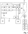
- FIGURE shows a schematic representation of an exemplary embodiment of a device 10 according to the invention for detecting a wing 12 of a door or the like. These are in the present case, for example, the wing 12 a revolving door.
- the locking device 10 comprises at least one electric motor 14 operated as a generator; 16, the motor shaft is connected via a power transmission unit with the wing 12, that a respective movement of the wing 12 with a respective movement of the motor shaft is accompanied.
- the power transmission unit inter alia, in each case in particular also a transmission 18; 20 include.
- the motor terminals of at least one electric motor 14 operating as a generator; 16 are connected for damping the wing movements to a damping circuit 22, wherein according to the in the single Fig. 1 illustrated embodiment, only the motor terminals of the electric motor 14 are connected to such a damping circuit 22. In the present case, of the two electric motors 14, 16 so only the electric motor 14 serves as a damping motor.
- the motor shaft of at least one electric motor 14 acting as a generator; 16 be acted upon by a brake unit 24, wherein according to the in the Fig. 1 illustrated embodiment, only the motor shaft of the electric motor 16 can be acted upon by such a brake unit 24.
- the brake unit 24 may in particular comprise an electromagnetic brake.
- the locking device 10 includes control electronics with an evaluation and / or control unit 46, via which the brake unit 24 can be controlled.
- At least one electric motor 14 operated as a generator; 16 may be connected via its motor terminals to a charging circuit for charging an energy storage device 28.
- a charging circuit for charging an energy storage device 28.
- the charging circuit is just like the damping circuit and the evaluation and / or control unit 26 part of the evaluation and / or control electronics of the locking device 10.
- the damping circuit 22 may also be integrated in the evaluation and / or control unit 26.
- the evaluation and / or control unit 26 can be supplied with electrical energy. It is thus a self-sufficient operation without supply of electrical energy from the outside possible.
- the brake unit 24 is either monostable operable in accordance with the working current principle or bistable operable.
- the locking device thus comprises two each operated as a generator electric motors 14; 16, one of which, namely the electric motor 14, is connected via its motor terminals to the damping circuit 22 and the other, namely the electric motor 16, via its motor terminals to the charging circuit for charging the energy storage 28.
- the motor shaft of the electric motor 16 connected to the charging circuit via its motor terminals and / or the motor shaft of the electric motor 14 connected to the damping circuit 22 via the motor terminals can be acted upon by the brake unit 24 to determine the wing 12.
- each electric motor is associated with such a brake unit.
- only the motor shaft of the connected via its motor terminals to the charging circuit for charging the energy storage device 28 electric motor 16 can be acted upon by a brake unit 24.
- the damping circuit 22 which is associated with the associated energy storage 28 of the evaluation and control electronics as well as the charging circuit, can be controlled via the evaluation and / or control unit 26. As already mentioned, This damping circuit 22 can also be integrated in the evaluation and / or control unit 26.
- the damping circuit 22 connected to the motor terminals of the electric motor 14 serving as a damping motor may comprise at least one switching element which can be activated via the evaluation and / or control unit 26 and via which, for example, a pulse width modulation of the motor current can be carried out.
- the movement of the wing 12 can be attenuated in particular as a function of the position, speed and / or direction of rotation of the wing 12 by a corresponding pulse width-modulated short-circuit, for example, of the electric motor 14 serving as a damping motor.
- the brake unit 24 can be controlled via the evaluation and / or control unit 26 in particular for generating a time-limited determination of the wing 12.
- the brake unit 24 via the evaluation and / or control unit 26, for example, for setting a predetermined closing delay of the wing 12 can be controlled.
- the brake unit 24 can be controlled via the evaluation and / or control unit 26 as a function of output signals of a safety sensor.
- both wings 12 may each have at least one electric motor 14; 16 associated and for determining the two wings 12 respectively the motor shaft at least one of a respective wing 12 associated electric motor 14; 16 be acted upon by a brake unit 24.
- the closing sequence of the two wings 12 can be controlled and / or regulated.
- the wing 12 associated brake unit 24 via the evaluation and / or control unit 26 also be controlled so that a respective determination of the wing 12 is released in case of fire. This ensures that the wing is closed in case of fire by the associated mechanical memory.
- the evaluation and / or control unit 26, the brake unit 24 and / or the damping circuit 22 thus, for example, in response to a signal 30, which in the case of a closing delay, for example by a switch 32 and / or a personal detector 34 and / or by a safety sensor 36 and / or in the case of a fire door by a fire detector and / or in the case of a two-leaf door with a fixed leaf and a moving leaf by a closing order specification 40 and / or the like can be predetermined.
- an additional battery or an additional battery 42 for supplying the evaluation and / or control unit 26 may be provided with electrical energy.
- the energy storage 28, 28 'of the two wings 12 associated locking devices and door closers can be coupled together.
- a bistable detection is thus always enough electrical energy available when a wing is moved in each case while the determination of the other must be kept, as has already been explained in more detail.
- the locking device 10 may be integrated in particular in a door closer 44 with a mechanical energy storage 46 which is charged by manually opening the door leaf 12 with potential energy, which is used to close the door leaf 12.
- the mechanical energy store 46 of the door closer 44 may in particular comprise a spring unit.
- a locking device 10 is thus in particular a time-limited detection of a door in a regeneratively damped door closer, for example, a closing delay in conjunction with a security sensor, for a closing sequence in a two-leaf door and / or depending on at least one fire detectors feasible.
- the generator-damped door closer can be provided with a monostable or bistable detection and / or the supply of detection can be ensured with electrical energy from a self-sufficient energy storage.
- the damping of the wing movements can be carried out in particular as in the DE 10 2015 200 284 B3 is described, the disclosure of which is included here.
- the spring unit of the mechanical energy store 46 When opening the door leaf 12, the spring unit of the mechanical energy store 46 is tensioned. At the same time, the two electric motors 14, 16 rotate.
- the electric motor 16, which serves as the generator motor, generates electrical energy via the charging circuit, which energy is stored in the energy store 28, whose state can be monitored by the evaluation and / or control unit 26.
- the energy store 28 supplies the evaluation and / or control unit 26 with electrical energy.
- the movements of the wing 12 are in dependence on the position, speed and / or direction of rotation of the wing 12 by the evaluation and / or control unit 26 via the damping circuit 22, for example, by a pulse width modulated short circuit of the motor terminals as Damping motor serving electric motor 14 damped.
- Position, speed and / or direction of rotation of the wing 12 can be detected via corresponding measuring circuits 48 and transmitted to the evaluation and / or control unit 26.
- a time-limited determination of the wing 12 by a corresponding control of the generator motor serving as a generator 16 associated brake unit 24 by the evaluation and / or control unit 26 is possible.
Landscapes
- Engineering & Computer Science (AREA)
- Business, Economics & Management (AREA)
- Emergency Management (AREA)
- Power Engineering (AREA)
- Mechanical Engineering (AREA)
- Physics & Mathematics (AREA)
- Electromagnetism (AREA)
- Power-Operated Mechanisms For Wings (AREA)
Applications Claiming Priority (1)
| Application Number | Priority Date | Filing Date | Title |
|---|---|---|---|
| DE102017201939.5A DE102017201939A1 (de) | 2017-02-08 | 2017-02-08 | Feststelleinrichtung |
Publications (2)
| Publication Number | Publication Date |
|---|---|
| EP3361027A1 true EP3361027A1 (fr) | 2018-08-15 |
| EP3361027B1 EP3361027B1 (fr) | 2020-07-29 |
Family
ID=60673657
Family Applications (1)
| Application Number | Title | Priority Date | Filing Date |
|---|---|---|---|
| EP17207592.1A Active EP3361027B1 (fr) | 2017-02-08 | 2017-12-15 | Dispositif de détermination |
Country Status (3)
| Country | Link |
|---|---|
| US (1) | US20180223578A1 (fr) |
| EP (1) | EP3361027B1 (fr) |
| DE (1) | DE102017201939A1 (fr) |
Families Citing this family (1)
| Publication number | Priority date | Publication date | Assignee | Title |
|---|---|---|---|---|
| SE546976C2 (en) * | 2022-12-14 | 2025-03-18 | Assa Abloy Ab | Arrangement and access member system |
Citations (5)
| Publication number | Priority date | Publication date | Assignee | Title |
|---|---|---|---|---|
| DE19726021A1 (de) * | 1997-06-19 | 1998-12-24 | Geze Gmbh & Co | Antrieb für einen Flügel einer Tür, eines Fensters doer dergleichen |
| DE10023760A1 (de) * | 1999-06-15 | 2000-12-21 | Geze Gmbh | Schließfolgesteuerungseinrichtung |
| EP1936089A1 (fr) * | 2006-12-13 | 2008-06-25 | DORMA GmbH + Co. KG | Mécanisme d'entraînement pour portes battantes |
| DE102015200284B3 (de) | 2015-01-13 | 2015-10-29 | Geze Gmbh | Bremsvorrichtung für einen beweglichen Türflügel und einen korrespondierenden Türschließer |
| EP2963218A1 (fr) * | 2014-06-30 | 2016-01-06 | GEZE GmbH | Dispositif de blocage pour un dispositif de commande de séquence de fermeture d'une installation de porte pivotante à deux battants |
Family Cites Families (10)
| Publication number | Priority date | Publication date | Assignee | Title |
|---|---|---|---|---|
| FI78767C (fi) * | 1987-07-09 | 1989-09-11 | Waertsilae Oy Ab | Foerfarande och arrangemang foer optimering av funktionen hos en doerrstaengare. |
| US5018304A (en) * | 1990-05-10 | 1991-05-28 | F. L. Saino Manufacturing Co. | Door operator |
| US6078159A (en) * | 1999-02-17 | 2000-06-20 | The Chamberlain Group, Inc. | Method and apparatus for programming a logic board from switching power |
| US20090260289A1 (en) * | 2008-04-18 | 2009-10-22 | Michael Carpenter | Door Safety System |
| US8390219B2 (en) * | 2010-07-29 | 2013-03-05 | Yale Security Inc. | Door operator with electrical back check feature |
| DE102011055491A1 (de) * | 2011-11-18 | 2013-05-23 | Dorma Gmbh + Co. Kg | Servotürschließer |
| CA2873273C (fr) * | 2012-05-08 | 2020-07-21 | Schlage Lock Company Llc | Systeme ferme-porte |
| WO2016113431A1 (fr) * | 2015-01-18 | 2016-07-21 | Assa Abloy Sicherheitstechnik Gmbh | Mécanisme d'entraînement de porte composé d'un entraînement principal et d'un entraînement auxiliaire |
| US11377893B2 (en) * | 2016-12-22 | 2022-07-05 | Assa Abloy Entrance Systems Ab | Closing speed control in power off |
| DE102017201950A1 (de) * | 2017-02-08 | 2018-08-09 | Geze Gmbh | Bremsvorrichtung |
-
2017
- 2017-02-08 DE DE102017201939.5A patent/DE102017201939A1/de active Pending
- 2017-12-15 EP EP17207592.1A patent/EP3361027B1/fr active Active
-
2018
- 2018-02-06 US US15/889,889 patent/US20180223578A1/en not_active Abandoned
Patent Citations (5)
| Publication number | Priority date | Publication date | Assignee | Title |
|---|---|---|---|---|
| DE19726021A1 (de) * | 1997-06-19 | 1998-12-24 | Geze Gmbh & Co | Antrieb für einen Flügel einer Tür, eines Fensters doer dergleichen |
| DE10023760A1 (de) * | 1999-06-15 | 2000-12-21 | Geze Gmbh | Schließfolgesteuerungseinrichtung |
| EP1936089A1 (fr) * | 2006-12-13 | 2008-06-25 | DORMA GmbH + Co. KG | Mécanisme d'entraînement pour portes battantes |
| EP2963218A1 (fr) * | 2014-06-30 | 2016-01-06 | GEZE GmbH | Dispositif de blocage pour un dispositif de commande de séquence de fermeture d'une installation de porte pivotante à deux battants |
| DE102015200284B3 (de) | 2015-01-13 | 2015-10-29 | Geze Gmbh | Bremsvorrichtung für einen beweglichen Türflügel und einen korrespondierenden Türschließer |
Also Published As
| Publication number | Publication date |
|---|---|
| EP3361027B1 (fr) | 2020-07-29 |
| US20180223578A1 (en) | 2018-08-09 |
| DE102017201939A1 (de) | 2018-08-09 |
Similar Documents
| Publication | Publication Date | Title |
|---|---|---|
| EP3325748B1 (fr) | Élément de porte muni d'un dispositif amortisseur pilotable | |
| EP2780526B1 (fr) | Ferme-porte asservi | |
| DE102010024755B4 (de) | Brandschutzschiebetür und Betriebsverfahren hierfür | |
| EP3417135B1 (fr) | Dispositif de freinage d'un battant de porte mobile et dispositif de fermeture de porte correspondant | |
| EP3245732B1 (fr) | Entraînement électromécanique pour l'actionnement d'un battant mobile et porte correspondante | |
| DE4231984A1 (de) | Elektromechanischer Drehtürantrieb | |
| EP3361029B1 (fr) | Dispositif d'entraînement pour un battant de porte ou de fenêtre | |
| WO2022167043A1 (fr) | Procédé d'assistance motorisée du mouvement d'une porte de véhicule | |
| EP2188476B1 (fr) | Entraînement linéaire pour portes coulissantes ou similaires | |
| DE102010014806A1 (de) | Torantriebsvorrichtung, damit versehener Gebäudeabschluss, Torsystem und Herstell- und Antriebsverfahren | |
| CH650056A5 (en) | Control circuit for a device for keeping shut a door, especially swing door, mounted so as to be movable transversely to the door plane | |
| EP3361027B1 (fr) | Dispositif de détermination | |
| DE102012210588A1 (de) | Automatische Drehtüranlage sowie Verfahren zum Betrieb einer automatischen Drehtüranlage | |
| EP3361030B1 (fr) | Entraînement pour un battant de porte ou de fenêtre | |
| EP3258045A1 (fr) | Entrainement de porte | |
| EP3361034B1 (fr) | Installation d'ouverture fixe et/ou d'ouverture d'urgence | |
| DE102016210986A1 (de) | Vorrichtung zum Feststellen eines Tür- oder Fensterflügels | |
| EP2944754B1 (fr) | Système d'entraînement pour une porte | |
| EP3064685B1 (fr) | Dispositif de commande de porte et procede de commande d'une porte | |
| EP3575531B1 (fr) | Système de fixation d'un battant de porte ou de fenêtre | |
| EP1612363B1 (fr) | Ensemble de porte coulissante automatique | |
| DE102013207453A1 (de) | Schließvorrichtung eines Gebäudes mit einer elektromotorischen Antriebsvorrichtung | |
| EP3067510B1 (fr) | Entrainement pour une tenture comprenant une alimentation d'urgence pour un commutateur de fin de course electronique | |
| EP4476422B1 (fr) | Procédé de réglage automatique d'une force de retenue d'un ferme-porte et ferme-porte pour une porte | |
| DE102008060325B4 (de) | Fenster, insbesondere Dachschiebefenster, mit einer Klemmschutzeinrichtung |
Legal Events
| Date | Code | Title | Description |
|---|---|---|---|
| PUAI | Public reference made under article 153(3) epc to a published international application that has entered the european phase |
Free format text: ORIGINAL CODE: 0009012 |
|
| STAA | Information on the status of an ep patent application or granted ep patent |
Free format text: STATUS: THE APPLICATION HAS BEEN PUBLISHED |
|
| AK | Designated contracting states |
Kind code of ref document: A1 Designated state(s): AL AT BE BG CH CY CZ DE DK EE ES FI FR GB GR HR HU IE IS IT LI LT LU LV MC MK MT NL NO PL PT RO RS SE SI SK SM TR |
|
| AX | Request for extension of the european patent |
Extension state: BA ME |
|
| STAA | Information on the status of an ep patent application or granted ep patent |
Free format text: STATUS: REQUEST FOR EXAMINATION WAS MADE |
|
| 17P | Request for examination filed |
Effective date: 20190212 |
|
| RBV | Designated contracting states (corrected) |
Designated state(s): AL AT BE BG CH CY CZ DE DK EE ES FI FR GB GR HR HU IE IS IT LI LT LU LV MC MK MT NL NO PL PT RO RS SE SI SK SM TR |
|
| STAA | Information on the status of an ep patent application or granted ep patent |
Free format text: STATUS: EXAMINATION IS IN PROGRESS |
|
| 17Q | First examination report despatched |
Effective date: 20190619 |
|
| GRAP | Despatch of communication of intention to grant a patent |
Free format text: ORIGINAL CODE: EPIDOSNIGR1 |
|
| STAA | Information on the status of an ep patent application or granted ep patent |
Free format text: STATUS: GRANT OF PATENT IS INTENDED |
|
| INTG | Intention to grant announced |
Effective date: 20200323 |
|
| GRAS | Grant fee paid |
Free format text: ORIGINAL CODE: EPIDOSNIGR3 |
|
| GRAA | (expected) grant |
Free format text: ORIGINAL CODE: 0009210 |
|
| STAA | Information on the status of an ep patent application or granted ep patent |
Free format text: STATUS: THE PATENT HAS BEEN GRANTED |
|
| AK | Designated contracting states |
Kind code of ref document: B1 Designated state(s): AL AT BE BG CH CY CZ DE DK EE ES FI FR GB GR HR HU IE IS IT LI LT LU LV MC MK MT NL NO PL PT RO RS SE SI SK SM TR |
|
| REG | Reference to a national code |
Ref country code: CH Ref legal event code: EP |
|
| REG | Reference to a national code |
Ref country code: AT Ref legal event code: REF Ref document number: 1295992 Country of ref document: AT Kind code of ref document: T Effective date: 20200815 |
|
| REG | Reference to a national code |
Ref country code: IE Ref legal event code: FG4D Free format text: LANGUAGE OF EP DOCUMENT: GERMAN |
|
| REG | Reference to a national code |
Ref country code: DE Ref legal event code: R096 Ref document number: 502017006409 Country of ref document: DE |
|
| REG | Reference to a national code |
Ref country code: LT Ref legal event code: MG4D |
|
| REG | Reference to a national code |
Ref country code: NL Ref legal event code: MP Effective date: 20200729 |
|
| PG25 | Lapsed in a contracting state [announced via postgrant information from national office to epo] |
Ref country code: FI Free format text: LAPSE BECAUSE OF FAILURE TO SUBMIT A TRANSLATION OF THE DESCRIPTION OR TO PAY THE FEE WITHIN THE PRESCRIBED TIME-LIMIT Effective date: 20200729 Ref country code: PT Free format text: LAPSE BECAUSE OF FAILURE TO SUBMIT A TRANSLATION OF THE DESCRIPTION OR TO PAY THE FEE WITHIN THE PRESCRIBED TIME-LIMIT Effective date: 20201130 Ref country code: ES Free format text: LAPSE BECAUSE OF FAILURE TO SUBMIT A TRANSLATION OF THE DESCRIPTION OR TO PAY THE FEE WITHIN THE PRESCRIBED TIME-LIMIT Effective date: 20200729 Ref country code: LT Free format text: LAPSE BECAUSE OF FAILURE TO SUBMIT A TRANSLATION OF THE DESCRIPTION OR TO PAY THE FEE WITHIN THE PRESCRIBED TIME-LIMIT Effective date: 20200729 Ref country code: GR Free format text: LAPSE BECAUSE OF FAILURE TO SUBMIT A TRANSLATION OF THE DESCRIPTION OR TO PAY THE FEE WITHIN THE PRESCRIBED TIME-LIMIT Effective date: 20201030 Ref country code: NO Free format text: LAPSE BECAUSE OF FAILURE TO SUBMIT A TRANSLATION OF THE DESCRIPTION OR TO PAY THE FEE WITHIN THE PRESCRIBED TIME-LIMIT Effective date: 20201029 Ref country code: HR Free format text: LAPSE BECAUSE OF FAILURE TO SUBMIT A TRANSLATION OF THE DESCRIPTION OR TO PAY THE FEE WITHIN THE PRESCRIBED TIME-LIMIT Effective date: 20200729 Ref country code: SE Free format text: LAPSE BECAUSE OF FAILURE TO SUBMIT A TRANSLATION OF THE DESCRIPTION OR TO PAY THE FEE WITHIN THE PRESCRIBED TIME-LIMIT Effective date: 20200729 Ref country code: BG Free format text: LAPSE BECAUSE OF FAILURE TO SUBMIT A TRANSLATION OF THE DESCRIPTION OR TO PAY THE FEE WITHIN THE PRESCRIBED TIME-LIMIT Effective date: 20201029 |
|
| PG25 | Lapsed in a contracting state [announced via postgrant information from national office to epo] |
Ref country code: IS Free format text: LAPSE BECAUSE OF FAILURE TO SUBMIT A TRANSLATION OF THE DESCRIPTION OR TO PAY THE FEE WITHIN THE PRESCRIBED TIME-LIMIT Effective date: 20201129 Ref country code: PL Free format text: LAPSE BECAUSE OF FAILURE TO SUBMIT A TRANSLATION OF THE DESCRIPTION OR TO PAY THE FEE WITHIN THE PRESCRIBED TIME-LIMIT Effective date: 20200729 Ref country code: RS Free format text: LAPSE BECAUSE OF FAILURE TO SUBMIT A TRANSLATION OF THE DESCRIPTION OR TO PAY THE FEE WITHIN THE PRESCRIBED TIME-LIMIT Effective date: 20200729 Ref country code: LV Free format text: LAPSE BECAUSE OF FAILURE TO SUBMIT A TRANSLATION OF THE DESCRIPTION OR TO PAY THE FEE WITHIN THE PRESCRIBED TIME-LIMIT Effective date: 20200729 |
|
| PG25 | Lapsed in a contracting state [announced via postgrant information from national office to epo] |
Ref country code: NL Free format text: LAPSE BECAUSE OF FAILURE TO SUBMIT A TRANSLATION OF THE DESCRIPTION OR TO PAY THE FEE WITHIN THE PRESCRIBED TIME-LIMIT Effective date: 20200729 |
|
| PG25 | Lapsed in a contracting state [announced via postgrant information from national office to epo] |
Ref country code: CZ Free format text: LAPSE BECAUSE OF FAILURE TO SUBMIT A TRANSLATION OF THE DESCRIPTION OR TO PAY THE FEE WITHIN THE PRESCRIBED TIME-LIMIT Effective date: 20200729 Ref country code: DK Free format text: LAPSE BECAUSE OF FAILURE TO SUBMIT A TRANSLATION OF THE DESCRIPTION OR TO PAY THE FEE WITHIN THE PRESCRIBED TIME-LIMIT Effective date: 20200729 Ref country code: RO Free format text: LAPSE BECAUSE OF FAILURE TO SUBMIT A TRANSLATION OF THE DESCRIPTION OR TO PAY THE FEE WITHIN THE PRESCRIBED TIME-LIMIT Effective date: 20200729 Ref country code: IT Free format text: LAPSE BECAUSE OF FAILURE TO SUBMIT A TRANSLATION OF THE DESCRIPTION OR TO PAY THE FEE WITHIN THE PRESCRIBED TIME-LIMIT Effective date: 20200729 Ref country code: EE Free format text: LAPSE BECAUSE OF FAILURE TO SUBMIT A TRANSLATION OF THE DESCRIPTION OR TO PAY THE FEE WITHIN THE PRESCRIBED TIME-LIMIT Effective date: 20200729 Ref country code: SM Free format text: LAPSE BECAUSE OF FAILURE TO SUBMIT A TRANSLATION OF THE DESCRIPTION OR TO PAY THE FEE WITHIN THE PRESCRIBED TIME-LIMIT Effective date: 20200729 |
|
| REG | Reference to a national code |
Ref country code: DE Ref legal event code: R097 Ref document number: 502017006409 Country of ref document: DE |
|
| PG25 | Lapsed in a contracting state [announced via postgrant information from national office to epo] |
Ref country code: AL Free format text: LAPSE BECAUSE OF FAILURE TO SUBMIT A TRANSLATION OF THE DESCRIPTION OR TO PAY THE FEE WITHIN THE PRESCRIBED TIME-LIMIT Effective date: 20200729 |
|
| PLBE | No opposition filed within time limit |
Free format text: ORIGINAL CODE: 0009261 |
|
| STAA | Information on the status of an ep patent application or granted ep patent |
Free format text: STATUS: NO OPPOSITION FILED WITHIN TIME LIMIT |
|
| PG25 | Lapsed in a contracting state [announced via postgrant information from national office to epo] |
Ref country code: SK Free format text: LAPSE BECAUSE OF FAILURE TO SUBMIT A TRANSLATION OF THE DESCRIPTION OR TO PAY THE FEE WITHIN THE PRESCRIBED TIME-LIMIT Effective date: 20200729 |
|
| 26N | No opposition filed |
Effective date: 20210430 |
|
| REG | Reference to a national code |
Ref country code: CH Ref legal event code: PL |
|
| PG25 | Lapsed in a contracting state [announced via postgrant information from national office to epo] |
Ref country code: MC Free format text: LAPSE BECAUSE OF FAILURE TO SUBMIT A TRANSLATION OF THE DESCRIPTION OR TO PAY THE FEE WITHIN THE PRESCRIBED TIME-LIMIT Effective date: 20200729 Ref country code: SI Free format text: LAPSE BECAUSE OF FAILURE TO SUBMIT A TRANSLATION OF THE DESCRIPTION OR TO PAY THE FEE WITHIN THE PRESCRIBED TIME-LIMIT Effective date: 20200729 |
|
| REG | Reference to a national code |
Ref country code: BE Ref legal event code: MM Effective date: 20201231 |
|
| PG25 | Lapsed in a contracting state [announced via postgrant information from national office to epo] |
Ref country code: LU Free format text: LAPSE BECAUSE OF NON-PAYMENT OF DUE FEES Effective date: 20201215 Ref country code: IE Free format text: LAPSE BECAUSE OF NON-PAYMENT OF DUE FEES Effective date: 20201215 Ref country code: FR Free format text: LAPSE BECAUSE OF NON-PAYMENT OF DUE FEES Effective date: 20201231 |
|
| PG25 | Lapsed in a contracting state [announced via postgrant information from national office to epo] |
Ref country code: LI Free format text: LAPSE BECAUSE OF NON-PAYMENT OF DUE FEES Effective date: 20201231 Ref country code: CH Free format text: LAPSE BECAUSE OF NON-PAYMENT OF DUE FEES Effective date: 20201231 |
|
| PG25 | Lapsed in a contracting state [announced via postgrant information from national office to epo] |
Ref country code: TR Free format text: LAPSE BECAUSE OF FAILURE TO SUBMIT A TRANSLATION OF THE DESCRIPTION OR TO PAY THE FEE WITHIN THE PRESCRIBED TIME-LIMIT Effective date: 20200729 Ref country code: MT Free format text: LAPSE BECAUSE OF FAILURE TO SUBMIT A TRANSLATION OF THE DESCRIPTION OR TO PAY THE FEE WITHIN THE PRESCRIBED TIME-LIMIT Effective date: 20200729 Ref country code: CY Free format text: LAPSE BECAUSE OF FAILURE TO SUBMIT A TRANSLATION OF THE DESCRIPTION OR TO PAY THE FEE WITHIN THE PRESCRIBED TIME-LIMIT Effective date: 20200729 |
|
| PG25 | Lapsed in a contracting state [announced via postgrant information from national office to epo] |
Ref country code: MK Free format text: LAPSE BECAUSE OF FAILURE TO SUBMIT A TRANSLATION OF THE DESCRIPTION OR TO PAY THE FEE WITHIN THE PRESCRIBED TIME-LIMIT Effective date: 20200729 |
|
| PG25 | Lapsed in a contracting state [announced via postgrant information from national office to epo] |
Ref country code: BE Free format text: LAPSE BECAUSE OF NON-PAYMENT OF DUE FEES Effective date: 20201231 |
|
| GBPC | Gb: european patent ceased through non-payment of renewal fee |
Effective date: 20211215 |
|
| PG25 | Lapsed in a contracting state [announced via postgrant information from national office to epo] |
Ref country code: GB Free format text: LAPSE BECAUSE OF NON-PAYMENT OF DUE FEES Effective date: 20211215 |
|
| P01 | Opt-out of the competence of the unified patent court (upc) registered |
Effective date: 20230510 |
|
| REG | Reference to a national code |
Ref country code: AT Ref legal event code: MM01 Ref document number: 1295992 Country of ref document: AT Kind code of ref document: T Effective date: 20221215 |
|
| PG25 | Lapsed in a contracting state [announced via postgrant information from national office to epo] |
Ref country code: AT Free format text: LAPSE BECAUSE OF NON-PAYMENT OF DUE FEES Effective date: 20221215 |
|
| PG25 | Lapsed in a contracting state [announced via postgrant information from national office to epo] |
Ref country code: AT Free format text: LAPSE BECAUSE OF NON-PAYMENT OF DUE FEES Effective date: 20221215 |
|
| PGFP | Annual fee paid to national office [announced via postgrant information from national office to epo] |
Ref country code: DE Payment date: 20251231 Year of fee payment: 9 |
|
| PGFP | Annual fee paid to national office [announced via postgrant information from national office to epo] |
Ref country code: AT Payment date: 20260410 Year of fee payment: 5 |