EP3364182A1 - Dispositif d'électrolyse - Google Patents
Dispositif d'électrolyse Download PDFInfo
- Publication number
- EP3364182A1 EP3364182A1 EP18156879.1A EP18156879A EP3364182A1 EP 3364182 A1 EP3364182 A1 EP 3364182A1 EP 18156879 A EP18156879 A EP 18156879A EP 3364182 A1 EP3364182 A1 EP 3364182A1
- Authority
- EP
- European Patent Office
- Prior art keywords
- cell
- carbon electrode
- electrode
- carbon
- liquid
- Prior art date
- Legal status (The legal status is an assumption and is not a legal conclusion. Google has not performed a legal analysis and makes no representation as to the accuracy of the status listed.)
- Withdrawn
Links
Images









Classifications
-
- G—PHYSICS
- G01—MEASURING; TESTING
- G01N—INVESTIGATING OR ANALYSING MATERIALS BY DETERMINING THEIR CHEMICAL OR PHYSICAL PROPERTIES
- G01N21/00—Investigating or analysing materials by the use of optical means, i.e. using sub-millimetre waves, infrared, visible or ultraviolet light
- G01N21/62—Systems in which the material investigated is excited whereby it emits light or causes a change in wavelength of the incident light
- G01N21/71—Systems in which the material investigated is excited whereby it emits light or causes a change in wavelength of the incident light thermally excited
- G01N21/73—Systems in which the material investigated is excited whereby it emits light or causes a change in wavelength of the incident light thermally excited using plasma burners or torches
-
- C—CHEMISTRY; METALLURGY
- C25—ELECTROLYTIC OR ELECTROPHORETIC PROCESSES; APPARATUS THEREFOR
- C25B—ELECTROLYTIC OR ELECTROPHORETIC PROCESSES FOR THE PRODUCTION OF COMPOUNDS OR NON-METALS; APPARATUS THEREFOR
- C25B11/00—Electrodes; Manufacture thereof not otherwise provided for
- C25B11/04—Electrodes; Manufacture thereof not otherwise provided for characterised by the material
- C25B11/042—Electrodes formed of a single material
- C25B11/043—Carbon, e.g. diamond or graphene
-
- C—CHEMISTRY; METALLURGY
- C25—ELECTROLYTIC OR ELECTROPHORETIC PROCESSES; APPARATUS THEREFOR
- C25B—ELECTROLYTIC OR ELECTROPHORETIC PROCESSES FOR THE PRODUCTION OF COMPOUNDS OR NON-METALS; APPARATUS THEREFOR
- C25B9/00—Cells or assemblies of cells; Constructional parts of cells; Assemblies of constructional parts, e.g. electrode-diaphragm assemblies; Process-related cell features
- C25B9/40—Cells or assemblies of cells comprising electrodes made of particles; Assemblies of constructional parts thereof
-
- C—CHEMISTRY; METALLURGY
- C25—ELECTROLYTIC OR ELECTROPHORETIC PROCESSES; APPARATUS THEREFOR
- C25B—ELECTROLYTIC OR ELECTROPHORETIC PROCESSES FOR THE PRODUCTION OF COMPOUNDS OR NON-METALS; APPARATUS THEREFOR
- C25B9/00—Cells or assemblies of cells; Constructional parts of cells; Assemblies of constructional parts, e.g. electrode-diaphragm assemblies; Process-related cell features
- C25B9/60—Constructional parts of cells
- C25B9/63—Holders for electrodes; Positioning of the electrodes
-
- G—PHYSICS
- G01—MEASURING; TESTING
- G01N—INVESTIGATING OR ANALYSING MATERIALS BY DETERMINING THEIR CHEMICAL OR PHYSICAL PROPERTIES
- G01N1/00—Sampling; Preparing specimens for investigation
- G01N1/28—Preparing specimens for investigation including physical details of (bio-)chemical methods covered elsewhere, e.g. G01N33/50, C12Q
- G01N1/40—Concentrating samples
-
- G—PHYSICS
- G01—MEASURING; TESTING
- G01N—INVESTIGATING OR ANALYSING MATERIALS BY DETERMINING THEIR CHEMICAL OR PHYSICAL PROPERTIES
- G01N27/00—Investigating or analysing materials by the use of electric, electrochemical, or magnetic means
- G01N27/26—Investigating or analysing materials by the use of electric, electrochemical, or magnetic means by investigating electrochemical variables; by using electrolysis or electrophoresis
- G01N27/28—Electrolytic cell components
- G01N27/30—Electrodes, e.g. test electrodes; Half-cells
- G01N27/308—Electrodes, e.g. test electrodes; Half-cells at least partially made of carbon
-
- G—PHYSICS
- G01—MEASURING; TESTING
- G01N—INVESTIGATING OR ANALYSING MATERIALS BY DETERMINING THEIR CHEMICAL OR PHYSICAL PROPERTIES
- G01N27/00—Investigating or analysing materials by the use of electric, electrochemical, or magnetic means
- G01N27/26—Investigating or analysing materials by the use of electric, electrochemical, or magnetic means by investigating electrochemical variables; by using electrolysis or electrophoresis
- G01N27/403—Cells and electrode assemblies
-
- G—PHYSICS
- G01—MEASURING; TESTING
- G01N—INVESTIGATING OR ANALYSING MATERIALS BY DETERMINING THEIR CHEMICAL OR PHYSICAL PROPERTIES
- G01N1/00—Sampling; Preparing specimens for investigation
- G01N1/28—Preparing specimens for investigation including physical details of (bio-)chemical methods covered elsewhere, e.g. G01N33/50, C12Q
- G01N1/40—Concentrating samples
- G01N2001/4038—Concentrating samples electric methods, e.g. electromigration, electrophoresis, ionisation
-
- G—PHYSICS
- G01—MEASURING; TESTING
- G01N—INVESTIGATING OR ANALYSING MATERIALS BY DETERMINING THEIR CHEMICAL OR PHYSICAL PROPERTIES
- G01N21/00—Investigating or analysing materials by the use of optical means, i.e. using sub-millimetre waves, infrared, visible or ultraviolet light
- G01N21/62—Systems in which the material investigated is excited whereby it emits light or causes a change in wavelength of the incident light
- G01N21/66—Systems in which the material investigated is excited whereby it emits light or causes a change in wavelength of the incident light electrically excited, e.g. electroluminescence
- G01N21/67—Systems in which the material investigated is excited whereby it emits light or causes a change in wavelength of the incident light electrically excited, e.g. electroluminescence using electric arcs or discharges
-
- G—PHYSICS
- G01—MEASURING; TESTING
- G01N—INVESTIGATING OR ANALYSING MATERIALS BY DETERMINING THEIR CHEMICAL OR PHYSICAL PROPERTIES
- G01N21/00—Investigating or analysing materials by the use of optical means, i.e. using sub-millimetre waves, infrared, visible or ultraviolet light
- G01N21/62—Systems in which the material investigated is excited whereby it emits light or causes a change in wavelength of the incident light
- G01N21/66—Systems in which the material investigated is excited whereby it emits light or causes a change in wavelength of the incident light electrically excited, e.g. electroluminescence
- G01N21/69—Systems in which the material investigated is excited whereby it emits light or causes a change in wavelength of the incident light electrically excited, e.g. electroluminescence specially adapted for fluids, e.g. molten metal
-
- Y—GENERAL TAGGING OF NEW TECHNOLOGICAL DEVELOPMENTS; GENERAL TAGGING OF CROSS-SECTIONAL TECHNOLOGIES SPANNING OVER SEVERAL SECTIONS OF THE IPC; TECHNICAL SUBJECTS COVERED BY FORMER USPC CROSS-REFERENCE ART COLLECTIONS [XRACs] AND DIGESTS
- Y02—TECHNOLOGIES OR APPLICATIONS FOR MITIGATION OR ADAPTATION AGAINST CLIMATE CHANGE
- Y02E—REDUCTION OF GREENHOUSE GAS [GHG] EMISSIONS, RELATED TO ENERGY GENERATION, TRANSMISSION OR DISTRIBUTION
- Y02E60/00—Enabling technologies; Technologies with a potential or indirect contribution to GHG emissions mitigation
- Y02E60/30—Hydrogen technology
- Y02E60/36—Hydrogen production from non-carbon containing sources, e.g. by water electrolysis
Definitions
- the present invention relates to an electrolysis device including a carbon electrode.
- a material for electrodes used in electrolysis varies depending on the object of an electrolysis reaction. For example, to detect a metal ion present in a solution, it is important to select a material for electrodes that is compatible with the type of metal ion, and that is a material resistant to degradation of the electrode from repeated electrolysis reactions.
- Carbon electrodes are often used as anodes or as cathodes in electrochemistry.
- Carbon which is a material for carbon electrodes, is manufactured by consolidating particles of carbon, is brittle compared to metal electrodes, and bonding between the particles is liable to break under electrical forces or under physical forces such as contact. Namely, carbon electrodes have lower resistance to degradation than do metal electrodes.
- JP 2006-284240 A describes preventing degradation of glassy carbon due to heating at high temperature by making the surface roughness of the glassy carbon 10 ⁇ m or less.
- An exemplary embodiment of the present disclosure relates to using the shape of a carbon electrode to raise resistance to degradation and, as far as possible, to prevent particles from breaking off.
- An electrolysis device includes a cell containing a solution and a pair of electrodes installed in the cell.
- One electrode of the pair of electrodes is a carbon electrode.
- a liquid-contacting portion of the carbon electrode that makes contact with the solution in the cell is configured by only a flat face or a three-dimensional curved face.
- the flat face or three-dimensional curved face is a face having no vertices, side-edges, or rims.
- a three-dimensional curved face is a face which is curved, in three-dimensional space. The three-dimensional curved face may be curved in one or both of its two dimensions.
- the liquid-contacting portion of the carbon electrode that makes contact with the solution in the cell is configured by only a flat face or a three-dimensional curved face.
- the liquid-contacting portion does not include a shape such as a side-edge or vertex where high current density is liable to occur when a voltage is applied. This prevents particles of carbon breaking off from such side-edges or vertices as temperature rises, vibrations increase, or the like as a result of high energy load from increased current density.
- the electrolysis device comprises a cell for containing a solution, and a pair of electrodes installed in the cell.
- One of the pair of electrodes is a carbon electrode.
- a liquid-contacting portion of the carbon electrode for making contact with the solution in the cell is configured by only a flat face or a three-dimensional curved face.
- the pair of electrodes are solid electrodes, and a specific example thereof is rod electrodes or the like.
- the material of the electrodes so long as one electrode is carbon
- the material of the other is not particularly limited, so long as the material is a solid, conductive material, and the material thereof may be appropriately determined according to the type of detection substance, for example.
- the material of the other electrode may, for example, be a non-metal, may be a metal, or may be a mixture thereof.
- the material of the other electrode may, for example, include one type of non-metal, or may include two or more types of non-metal. Examples of the non-metal include carbon.
- the material of the other electrode may, for example, include one type of metal, or may include two or more types of metal.
- the metal include gold, platinum, copper, zinc, tin, nickel, palladium, titanium, molybdenum, chromium, and iron.
- the material of the electrode may be an alloy. Examples of the alloy include brass, steel, INCONEL (registered trademark), Nichrome, and stainless steel.
- the pair of electrodes may, for example, be the same material or different materials.
- the size of the electrodes is not particularly limited, as long as it is a size such that at least a portion of the electrode can be placed in the cell.
- the liquid-contacting portion of the carbon electrode is configured by only the flat face or the three-dimensional curved face, as described above.
- the flat face or three-dimensional curved face is a face that does not include any vertices, side-edges, or rims.
- the flat face or three-dimensional curved face may be defined as a continuous face that is a face such that when any given cross-section is taken of the liquid-contacting portion and an outline on the solution side of the liquid-contacting portion is written as a function, the outline is differentiable at all of the points thereon.
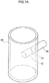
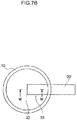
- one base face side of the cylindrical-shaped carbon electrode 30 is installed so as to stick out toward the interior of the cell 10 from a side face of the cell 10. Then, a peripheral rim of the base face becomes a side-edge 32.
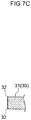
- a portion of the carbon electrode 30 that is positioned in the cell 10 (a liquid-contacting portion 31) then exhibits a rectangular cross-section as, for example, illustrated in Fig. 7C .
- the outline of the cross-section includes right angled vertices due to the side-edge 32, and thus the liquid-contacting portion 31 of the carbon electrode 30 is not configured with what is referred to in the present invention as only a "flat face" or "three-dimensional curved face".
- the outline of the cross-section is non-differentiable at the vertex. Due to adopting such a shape, the current density at the side-edge 32 portion tends to be high when a voltage is applied, resulting in particles of carbon being liable to break off during an electrolysis reaction. Such a carbon electrode 30 is not preferable for the electrolysis device of the present aspect.
- a tip end at one end of a cylindrical-shaped carbon electrode 30 is tapered into a conical shape.
- the tip end is installed so as to stick out toward the interior of the cell 10 from the side face of the cell 10. Then, the tip end is a vertex 33.
- the portion of the carbon electrode 30 that is positioned in the cell 10 then exhibits an arrowhead shape in cross-section through the tip end, as illustrated in Fig. 8C .
- the outline of the cross-section includes an angular vertex formed due to the vertex 33, and thus a liquid-contacting portion 31 of the carbon electrode 30 is not configured with what is referred to in the present invention as only a "flat face" or a"three-dimensional curved face". Note that the outline of the cross-section is non-differentiable at the vertex. Due to adopting such a shape, the current density at a portion at the vertex 33 tends to be high when a voltage is applied, and particles of carbon are liable to break off during an electrolysis reaction. Such a carbon electrode 30 is also not preferable for the electrolysis device of the present configuration.
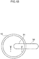
- one end of the cylindrical-shaped carbon electrode 30 has a hemispherical shape, and the carbon electrode 30 is installed such that the hemispherical shaped portion sticks out toward the interior of the cell 10 from the side face of the cell 10.
- the portion of the carbon electrode 30 that is positioned in the cell 10 exhibits a cross-section having an outline profile that, for example as illustrated in Fig. 1C , includes parallel straight lines that then curve into respective circular arcs meeting at the tip end.
- the outline of the cross-section section does not include any side-edges, vertices, or rims, and thus the liquid-contacting portion 31 of the carbon electrode 30 is configured by what is referred to in the present invention as only a "three-dimensional curved face". Note that the outline of the cross-section is differentiable at every point. Due to adopting such a shape, there are no portions where the current density tends to be extremely high when a voltage is applied, and particles of carbon become less liable to break off during an electrolysis reaction.
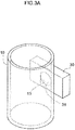
- a cylindrical-shaped carbon electrode 30 is installed in a state in which its length direction is orthogonal to the length direction of the cell 10, and in a state in which a portion of a side face of the carbon electrode 30 is exposed to the inside of the cell 10. Then, the portion of the carbon electrode 30 that is positioned in the cell 10 exhibits a cross-section which is circular arc shaped, for example as illustrated in Fig. 2C .
- the outline of the cross-section includes no side-edges, points, or rims, and thus the liquid-contacting portion 31 of the carbon electrode 30 is configured with what is referred to in the present invention as only a "three-dimensional curved face". Note that the outline of the cross-section is differentiable at every point. Due to adopting such a shape, there are no portions where the current density tends to be high when a voltage is applied, and particles of carbon become less liable to break off during an electrolysis reaction.
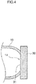
- a through hole 13 is provided penetrating through a side face of a cylindrical-shaped cell 10 at a portion where the thickness has been cut away.
- a flat plate-shaped carbon electrode 30 is installed so as to block off the through hole 13 from the outside.
- a flat face portion of the carbon electrode 30 facing the penetrating hole 13 is a liquid-contacting portion 31.
- the outline of a cross-section of the liquid-contacting portion 31 exhibits a straight line shape, and therefore includes no side-edges, points, or rims.
- the liquid-contacting portion 31 of the carbon electrode 30 is configured with what is referred to in the present invention as only a "flat face".
- the outline of the cross-section is differentiable at every point. Due to adopting such a shape, there are no portions where the current density tends to be extremely high when a voltage is applied, and particles of carbon are not liable to break off during an electrolysis reaction.
- an opening 14 may be provided with a shape as if part of the arc shaped portion has been cut away, and a flat plate-shaped carbon electrode 30 installed so as to block off the opening 14 from the outside.
- the flat face portion of the carbon electrode 30 facing the opening 14 is a liquid-contacting portion 31.
- the outline of the cross-section of the liquid-contacting portion 31 exhibits a straight line shape, and therefore has no side-edges, points, or rims.
- the liquid-contacting portion 31 of the carbon electrode 30 is configured with what is referred to in the present invention as only a "flat face".
- the outline of the cross-section is differentiable at every point. Due to adopting such a shape, there are no portions where the current density tends to be extremely high when a voltage is applied, and particles of carbon are not liable to break off during an electrolysis reaction.
- the solution is a liquid in which a material to be analyzed (detection substance) by an electrolysis reaction is dissolved, suspended, or dispersed.
- the liquid may, for example, be a liquid specimen, or may be a diluent of a solid specimen that has been, for example, suspended, dispersed, or dissolved in a medium.
- a neat solution of the specimen may, for example, be employed as it is as the liquid specimen, or the neat solution may be employed with a medium, for example, by suspending, dispersing, or dissolving the neat solution in the medium. So long as the medium is able to suspend, disperse, or dissolve the specimen, there are no particular limitations thereto, and examples of the medium include water and buffers.
- specimens taken from biological bodies
- environmental specimens samples
- metals examples thereof include urine, blood, hair, saliva, sweat, nails, and the like.
- the blood specimen may, for example, be erythrocytes, whole blood, serum, blood plasma, or the like.
- biological body examples include a human, a non-human animal, a plant, or the like.
- the non-human animal may, for example, be a mammal other than a human, a reptile, an amphibian, a fish, an insect, or the like.
- the environmental specimen is not particularly limited, and examples thereof include food, water, soil, the atmosphere, an air sample, or the like.
- examples of the food include fresh foods, and processed foods.
- Examples of the water include drinking water, underground water, river water, sea water, household effluent, and the like.
- the detection substance includes metals, chemical substances, and the like.
- the metal is not particularly limited, and examples of the metal include aluminum (Al), antimony (Sb), arsenic (As), barium (Ba), beryllium (Be), bismuth (Bi), cadmium (Cd), caesium (Cs), gadolinium (Gd), lead (Pb), mercury (Hg), nickel (Ni), palladium (Pd), platinum (Pt), tellurium (Te), thallium (Tl), thorium (Th), tin (Sn), tungsten (W), and uranium (U).
- the chemical substance include reagents, agricultural chemicals, and cosmetics. There may, for example, be a single type or two or more types of the detection substance.
- the liquid may, for example, include a reagent for separating the metal in the specimen.
- the reagent include chelating agents, masking agents, and the like.
- the chelating agent include dithizone, tiopronin, meso-2,3-dimercaptosuccinic acid (DMSA), sodium 2,3-dimercapto-1-propane sulfonate (DMPS), ethylenediaminetetraacetic acid (EDTA), nitrilotriacetic acid (NTA), ethylenediamine-N,N'-disuccinic acid (EDDS), and alpha lipoic acid.
- DMSA meso-2,3-dimercaptosuccinic acid
- DMPS sodium 2,3-dimercapto-1-propane sulfonate
- EDTA ethylenediaminetetraacetic acid
- NTA nitrilotriacetic acid
- EDDS ethylenediamine-N
- Masking in an analysis method mentioned herein deactivating the reactivity of SH groups, and may, for example, be performed by chemically modifying SH groups.
- the masking agent include maleimide, N-methylmaleimide, N-ethylmaleimide, N-phenylmaleimide, maleimidopropionic acid, iodoacetamide, and iodoacetic acid.
- the liquid may, for example, be a liquid that regulates pH.
- the pH in such cases is not particularly limited so long as it is a pH that is conducive to detection of the detection substance.
- the pH of the liquid can, for example, be regulated by a pH-regulating reagent that is an alkaline reagent, an acid reagent, or the like.
- Examples of the alkaline reagent include alkalis and aqueous solutions of alkalis.
- the alkali is not particularly limited, and examples include sodium hydroxide, lithium hydroxide, potassium hydroxide, and ammonia.
- Examples of the aqueous solutions of alkalis include aqueous solutions in which alkali is diluted by water or a buffer.
- the concentration of the alkali in the alkaline aqueous solution is not particularly limited, and may, for example, be from 0.01 mol/L to 5 mol/L.
- Examples of the acid reagent include acids and aqueous solutions of acids.
- the acid is not particularly limited, and examples include hydrochloric acid, sulfuric acid, acetic acid, boric acid, phosphoric acid, citric acid, malic acid, succinic acid, and nitric acid.
- Examples of the acid aqueous solutions include aqueous solutions in which acid is diluted by water or a buffer.
- the concentration of acid in the acid aqueous solution is not particularly limited, and may, for example, be from 0.01 mol/L to 5 mol/L.
- a containment space is provided in the cell below the pair of electrodes to contain any broken fragments from the carbon electrode.
- the containment space is provided in the cell in order to avoid such a situation arising, as much as possible.
- the containment space is provided below the pair of electrodes. Namely, the containment space is positioned below the lower-positioned electrode of the pair of electrodes.
- the containment space is preferably a space at the bottom portion of the cell 10 with an inner diameter that decreases on progression downward.
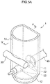
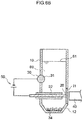
- the electrolysis device 1 of the present exemplary embodiment includes a cell 10, a pair of electrodes (a small electrode 20 and a carbon electrode 30), and a light receiver 40.
- the cell 10 exhibits a substantially cylindrical shape, having a portion of its side face as if truncated to form a flat face shape.
- a circular light-transmissive portion 11 is included in the flat face portion.
- the light receiver 40 is disposed outside the cell 10. Luminescence emitted by applying a voltage to the small electrode 20 and the carbon electrode 30 passes through the circular light-transmissive portion 11, and the light receiver 40 is disposed so as to be capable of receiving the luminescence of the detection substance.
- the small electrode 20 is disposed parallel to a liquid surface 61 of a solution 60, and a tip end of the small electrode 20 is disposed so as to abut the light-transmissive portion 11.
- the carbon electrode 30 having a cylindrical shape is disposed with a portion of its side face in the side face of the cell 10 on a side of the cell 10 facing the circular light-transmissive portion 11, such that the carbon electrode 30 intersects the vertical direction at a right angle, and this portion of the carbon electrode 30 is exposed to the interior of the cell 10.
- the length direction of the carbon electrode 30 and the length direction of the small electrode 20 are at skew-line positions with respect to each other.
- the liquid-contacting portion 31 of the carbon electrode 30 originates from the side face of a circular tube shape, and is thus configured with only a three-dimensional curved face (see Fig. 2A to Fig. 2C ).
- the small electrode 20 is covered by an insulator 22.
- a containment space 12 having an inner diameter that decreases on progression downward is provided further down below the small electrode 20 at the bottom portion of the cell 10.
- the solution 60 containing the detection substance is introduced into the tube of the cell 10 such that the solution 60 makes contact with the small electrode 20 and the carbon electrode 30.
- the small electrode 20 is installed parallel to the liquid surface 61 of the solution 60, and most of the surface of the small electrode 20 is covered by the insulator 22.
- the small electrode 20 and the light-transmissive portion 11 contact each other; however, the present embodiment is not limited thereto, and for example, the small electrode 20 may not make contact with the light-transmissive portion 11.
- the distance between the small electrode 20 and the light-transmissive portion 11 is not particularly limited, and may, for example, be from 0 cm to 0.5 cm.
- the material of the light-transmissive portion 11 is not particularly limited, and may, for example, be set as appropriate according to the wavelength of the luminescence, so long as it is a material that transmits luminescence emitted by applying voltage to the small electrode 20 and the carbon electrode 30.
- Examples of the material of the light-transmissive portion 11 include quartz glass, acrylic resin (PMMA), borosilicate glass, polycarbonate (PC), cyclo olefin polymer (COP), and polymethylpentene (TPX (registered trademark)).
- the size of the light-transmissive portion 11 is not particularly limited, so long as it is a size that enables transmission of luminescence emitted by applying voltage to the small electrode 20 and the carbon electrode 30.
- the cell 10 is a bottomed cylindrical shape having a portion of its side face truncated to form a flat face shape running along its length direction; however, the shape of the cell 10 is not limited thereto, and may be any desired shape.
- the material of cell 10 is not particularly limited, and examples include acrylic resin (PMMA), polypropylene (PP), polyethylene (PE), polyvinylchloride (PVC), polyethylene terephthalate (PET), and polystyrene (PS).
- the diameter of the cell 10 is, for example, from 0.3 cm to 1 cm
- the height of the cell 10 is, for example, from 0.9 cm to 5 cm.
- Into the cell 10 is introduced 0.3 cm 3 to 0.8 cm 3 of the solution 60.
- the light receiver 40 is not particularly limited, and examples include known optical measurement instruments such as CCDs, spectroscopy instruments, and so on.
- the light receiver 40 may, for example, be a transmitter that transmits the luminescence to the optical measurement instrument disposed outside the electrolysis device 1.
- Examples of the transmitter include a transmission path such as an optical fiber.
- the method of manufacturing the cell 10 is not particularly limited and the cell 10 may be a molded body manufactured by injection-molding or the like, or may be manufactured by forming a recess in a substrate such as a plate.
- the manufacturing method of the cell 10 is not particularly limited, and other examples thereof include lithography and machine cutting.
- a voltage is applied by a voltage application device 50 such that the small electrode 20 acts as the cathode and the carbon electrode 30 acts as the anode, as a concentration process to concentrate the detection substance in the vicinity of the small electrode 20, as illustrated in Fig. 6A .
- metal ions present in the solution 60 are attracted to the small electrode 20, this being the cathode.
- hydrogen ions in the solution 60 are also attracted to the small electrode 20 and gain electrons there to form hydrogen gas, resulting in bubbles 62 arising from the small electrode 20.
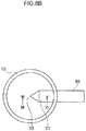
- a voltage is applied by the voltage application device 50 such that the small electrode 20 then acts as the anode and the carbon electrode 30 acts as the cathode, as illustrated in Fig. 6B , in a detection process to detect the detection substance that was concentrated in the vicinity of the small electrode 20 by the concentration process.
- plasma is generated from the metal ions that were attracted around the small electrode 20 by the prior concentration process, and the light generated as a result passes through the light-transmissive portion 11 and is received and detected by the light receiver 40.
- the present invention may be utilized in an electrolysis device provided with a carbon electrode.
Landscapes
- Chemical & Material Sciences (AREA)
- Chemical Kinetics & Catalysis (AREA)
- Electrochemistry (AREA)
- Engineering & Computer Science (AREA)
- Organic Chemistry (AREA)
- Metallurgy (AREA)
- Materials Engineering (AREA)
- Health & Medical Sciences (AREA)
- Life Sciences & Earth Sciences (AREA)
- Physics & Mathematics (AREA)
- General Health & Medical Sciences (AREA)
- General Physics & Mathematics (AREA)
- Immunology (AREA)
- Pathology (AREA)
- Biochemistry (AREA)
- Analytical Chemistry (AREA)
- Molecular Biology (AREA)
- Nuclear Medicine, Radiotherapy & Molecular Imaging (AREA)
- Plasma & Fusion (AREA)
- Electrolytic Production Of Non-Metals, Compounds, Apparatuses Therefor (AREA)
- Electrodes For Compound Or Non-Metal Manufacture (AREA)
Applications Claiming Priority (1)
| Application Number | Priority Date | Filing Date | Title |
|---|---|---|---|
| JP2017026679A JP2018131660A (ja) | 2017-02-16 | 2017-02-16 | 電気分解装置 |
Publications (1)
| Publication Number | Publication Date |
|---|---|
| EP3364182A1 true EP3364182A1 (fr) | 2018-08-22 |
Family
ID=61226454
Family Applications (1)
| Application Number | Title | Priority Date | Filing Date |
|---|---|---|---|
| EP18156879.1A Withdrawn EP3364182A1 (fr) | 2017-02-16 | 2018-02-15 | Dispositif d'électrolyse |
Country Status (4)
| Country | Link |
|---|---|
| US (1) | US20180230613A1 (fr) |
| EP (1) | EP3364182A1 (fr) |
| JP (1) | JP2018131660A (fr) |
| CN (1) | CN108489964B (fr) |
Citations (8)
| Publication number | Priority date | Publication date | Assignee | Title |
|---|---|---|---|---|
| US5160419A (en) * | 1990-08-01 | 1992-11-03 | Mitsubishi Petrochemical Company Limited | Electrode for a coulometric type of electrochemical detector |
| EP0876831A1 (fr) * | 1997-02-05 | 1998-11-11 | Jyh-Myng Zen | Procédé de décomposition électrochimique des polluants organiques |
| JP2006284240A (ja) | 2005-03-31 | 2006-10-19 | Toshiba Corp | 微量金属元素の定量分析方法 |
| JP2010222603A (ja) * | 2009-03-19 | 2010-10-07 | Furukawa Electric Co Ltd:The | 銅微粒子分散液の製造方法 |
| CN105424773A (zh) * | 2015-11-05 | 2016-03-23 | 中国石油天然气股份有限公司 | 一种用于土壤腐蚀电化学实验的电解池 |
| JP2016130734A (ja) | 2015-01-13 | 2016-07-21 | アークレイ株式会社 | プラズマ分光分析方法およびプラズマ分光分析装置 |
| CN205803201U (zh) * | 2016-07-04 | 2016-12-14 | 江苏苏纯环保科技有限公司 | 一种多相电氧化处理降解水的设备 |
| EP3273228A1 (fr) * | 2016-07-22 | 2018-01-24 | ARKRAY, Inc. | Procédé d'analyse spectroscopique de plasma et analyseur spectroscopique de plasma |
Family Cites Families (27)
| Publication number | Priority date | Publication date | Assignee | Title |
|---|---|---|---|---|
| US2752303A (en) * | 1954-09-02 | 1956-06-26 | Walter M Weil | Fused bath electrolysis of metal chlorides |
| US3383294A (en) * | 1965-01-15 | 1968-05-14 | Wood Lyle Russell | Process for production of misch metal and apparatus therefor |
| US3616356A (en) * | 1967-09-18 | 1971-10-26 | Clarence H Roy | Electrolysis in a particulate carbon packing |
| US4088548A (en) * | 1973-05-15 | 1978-05-09 | Townsend Douglas W | Electrolytic method and apparatus for refractory metals using a hollow carbon electrode |
| US4009413A (en) * | 1975-02-27 | 1977-02-22 | Spectrametrics, Incorporated | Plasma jet device and method of operating same |
| JPS5855763A (ja) * | 1981-09-29 | 1983-04-02 | Suga Shikenki Kk | 光量計用電解セル |
| DE3151398A1 (de) * | 1981-12-24 | 1983-07-07 | Gewerkschaft Eisenhütte Westfalia, 4670 Lünen | Verfahren und einrichtung zum vorzerkleinern von kunstkohlekoerpern, wie insbesondere elektroden, anoden u.dgl. fuer elektrolytische schmelzbaeder |
| US4684448A (en) * | 1984-10-03 | 1987-08-04 | Sumitomo Light Metal Industries, Ltd. | Process of producing neodymium-iron alloy |
| US5074988A (en) * | 1986-02-20 | 1991-12-24 | Raychem Corporation | Apparatus for monitoring an electrolyte |
| JPH06104912B2 (ja) * | 1988-04-01 | 1994-12-21 | 三菱原子燃料株式会社 | 四塩化ジルコニユウムと四塩化ハフニユウムを分離する方法及び電極 |
| WO1992015009A1 (fr) * | 1991-02-19 | 1992-09-03 | Tdk Corporation | Methode d'analyse d'une substance electrochimioluminescente et appareil a cet effet |
| US5376214A (en) * | 1992-09-22 | 1994-12-27 | Nissan Motor Co., Ltd. | Etching device |
| JP3261288B2 (ja) * | 1995-09-09 | 2002-02-25 | 新日本製鐵株式会社 | Icp分析に用いる試料の溶解供給装置 |
| US5980711A (en) * | 1996-06-10 | 1999-11-09 | Honda Giken Kogyo Kabushiki Kaisha | Electrolytic test machine |
| JPH10255681A (ja) * | 1997-03-13 | 1998-09-25 | Dainippon Printing Co Ltd | スリットタイプのシャドウマスクおよびその製造方法 |
| JPH10310890A (ja) * | 1997-05-08 | 1998-11-24 | Toyo Tanso Kk | 水又は水溶液の電解用電極板 |
| US6423193B1 (en) * | 1999-08-30 | 2002-07-23 | Case Western Reserve University | Nitrogen doped carbon electrodes |
| WO2005093394A1 (fr) * | 2004-03-25 | 2005-10-06 | Japan Advanced Institute Of Science And Technology | Equipement de generation de plasma |
| JP2005283193A (ja) * | 2004-03-29 | 2005-10-13 | Citizen Watch Co Ltd | 光学測定装置 |
| WO2008098044A2 (fr) * | 2007-02-06 | 2008-08-14 | Akvo Energy America, Inc. | Système de conversion énergétique |
| US20090260531A1 (en) * | 2008-04-18 | 2009-10-22 | Fujifilm Corporation | Aluminum alloy plate for lithographic printing plate, lithographic printing plate support, presensitized plate, method of manufacturing aluminum alloy plate for lithographic printing plate and method of manufacturing lithographic printing plate support |
| US8075750B2 (en) * | 2009-02-17 | 2011-12-13 | Mcalister Technologies, Llc | Electrolytic cell and method of use thereof |
| EP4060325B1 (fr) * | 2009-12-07 | 2024-08-21 | Meso Scale Technologies, LLC. | Lecteur de cartouche de dosage |
| CN102636431A (zh) * | 2012-03-08 | 2012-08-15 | 宁波大学 | 具有自洁功能的电致化学发光分析检测装置 |
| WO2014002364A1 (fr) * | 2012-06-28 | 2014-01-03 | パナソニック株式会社 | Dispositif d'analyse élémentaire pour échantillons liquides |
| CN104865239B (zh) * | 2014-02-21 | 2019-03-22 | 爱科来株式会社 | 等离子光谱分析方法 |
| EP3212572B1 (fr) * | 2014-10-21 | 2019-04-24 | West Virginia University Research Corporation | Méthodes et appareils de production de carbone |
-
2017
- 2017-02-16 JP JP2017026679A patent/JP2018131660A/ja active Pending
-
2018
- 2018-02-11 CN CN201810139549.7A patent/CN108489964B/zh active Active
- 2018-02-14 US US15/896,720 patent/US20180230613A1/en not_active Abandoned
- 2018-02-15 EP EP18156879.1A patent/EP3364182A1/fr not_active Withdrawn
Patent Citations (8)
| Publication number | Priority date | Publication date | Assignee | Title |
|---|---|---|---|---|
| US5160419A (en) * | 1990-08-01 | 1992-11-03 | Mitsubishi Petrochemical Company Limited | Electrode for a coulometric type of electrochemical detector |
| EP0876831A1 (fr) * | 1997-02-05 | 1998-11-11 | Jyh-Myng Zen | Procédé de décomposition électrochimique des polluants organiques |
| JP2006284240A (ja) | 2005-03-31 | 2006-10-19 | Toshiba Corp | 微量金属元素の定量分析方法 |
| JP2010222603A (ja) * | 2009-03-19 | 2010-10-07 | Furukawa Electric Co Ltd:The | 銅微粒子分散液の製造方法 |
| JP2016130734A (ja) | 2015-01-13 | 2016-07-21 | アークレイ株式会社 | プラズマ分光分析方法およびプラズマ分光分析装置 |
| CN105424773A (zh) * | 2015-11-05 | 2016-03-23 | 中国石油天然气股份有限公司 | 一种用于土壤腐蚀电化学实验的电解池 |
| CN205803201U (zh) * | 2016-07-04 | 2016-12-14 | 江苏苏纯环保科技有限公司 | 一种多相电氧化处理降解水的设备 |
| EP3273228A1 (fr) * | 2016-07-22 | 2018-01-24 | ARKRAY, Inc. | Procédé d'analyse spectroscopique de plasma et analyseur spectroscopique de plasma |
Also Published As
| Publication number | Publication date |
|---|---|
| JP2018131660A (ja) | 2018-08-23 |
| US20180230613A1 (en) | 2018-08-16 |
| CN108489964A (zh) | 2018-09-04 |
| CN108489964B (zh) | 2022-06-24 |
Similar Documents
| Publication | Publication Date | Title |
|---|---|---|
| KR102420443B1 (ko) | 플라즈마 분광 분석 방법 및 플라즈마 분광 분석 장치 | |
| CN105784675B (zh) | 等离子体分光分析方法和等离子体分光分析装置 | |
| EP3425375B1 (fr) | Procédé d'analyse par spectroscopie de plasma | |
| EP3364182A1 (fr) | Dispositif d'électrolyse | |
| Beinrohr et al. | Simultaneous Calibrationless Determination of Zinc, Cadmium, Lead, and Copper by Flow‐Through Stripping Chronopotentiometry | |
| CN107917906B (zh) | 等离子体分光分析方法和来自非靶材的等离子体发光的抑制剂 | |
| US20180230608A1 (en) | Electrolysis Device | |
| US20180024069A1 (en) | Plasma spectroscopic analysis method and plasma spectroscopic analyzer | |
| US10551323B2 (en) | Plasma spectroscopy analysis method | |
| Lu et al. | Inverted poly (vinyl chloride)–liquid membrane ion-selective electrodes for high-speed batch injection potentiometric analysis | |
| US10295471B2 (en) | Plasma spectroscopic analysis method and inhibitor of plasma emission derived from non-target | |
| JP6871088B2 (ja) | 炭素電極の洗浄方法 | |
| Caporali et al. | Determination of gold in alloys via potentiometric titration; an alternative to the fire assay | |
| Kounaves | Iridium Based Ultramicroelectrodes | |
| JP2019191052A (ja) | プラズマ分光分析方法 | |
| JP6480211B2 (ja) | プラズマ発生用チップ、プラズマ発生装置およびプラズマ分光分析方法 | |
| KR102236900B1 (ko) | 드롭 모드의 무전해 도금 방식을 이용한 금 나노구조체 제조 방법 | |
| Zaytsev et al. | SIMULTANEOUS DETERMINATION OF ZINC, CADMIUM, LEAD AND COPPER BY ANODIC STRIPPING VOLTAMMETRY AT A MERCURY FILM ELECTRODE. | |
| Pasullean et al. | Electrodeposition of lead on to a graphite probe for electrothermal atomic absorption spectrometry | |
| Alimarin et al. | Electrochemical methods of ultramicroanalysis | |
| KR19980042988A (ko) | 일체형 복합 미세전극 어레이 | |
| JP2019191051A (ja) | 測定システム及び測定デバイスの温度調節方法 | |
| Cai et al. | An Automated Electronic Tongue for In‐Situ Quick Monitoring of Trace Heavy Metals in Water Environment | |
| JP2019191053A (ja) | プラズマ分光分析方法 | |
| JP2019078559A (ja) | 炭素含有電極の処理方法及び測定容器 |
Legal Events
| Date | Code | Title | Description |
|---|---|---|---|
| PUAI | Public reference made under article 153(3) epc to a published international application that has entered the european phase |
Free format text: ORIGINAL CODE: 0009012 |
|
| STAA | Information on the status of an ep patent application or granted ep patent |
Free format text: STATUS: THE APPLICATION HAS BEEN PUBLISHED |
|
| AK | Designated contracting states |
Kind code of ref document: A1 Designated state(s): AL AT BE BG CH CY CZ DE DK EE ES FI FR GB GR HR HU IE IS IT LI LT LU LV MC MK MT NL NO PL PT RO RS SE SI SK SM TR |
|
| AX | Request for extension of the european patent |
Extension state: BA ME |
|
| STAA | Information on the status of an ep patent application or granted ep patent |
Free format text: STATUS: THE APPLICATION IS DEEMED TO BE WITHDRAWN |
|
| 18D | Application deemed to be withdrawn |
Effective date: 20190223 |