EP3366933A1 - Vis - Google Patents
Vis Download PDFInfo
- Publication number
- EP3366933A1 EP3366933A1 EP17196177.4A EP17196177A EP3366933A1 EP 3366933 A1 EP3366933 A1 EP 3366933A1 EP 17196177 A EP17196177 A EP 17196177A EP 3366933 A1 EP3366933 A1 EP 3366933A1
- Authority
- EP
- European Patent Office
- Prior art keywords
- threaded section
- auxiliary
- leading
- screw
- cutting unit
- Prior art date
- Legal status (The legal status is an assumption and is not a legal conclusion. Google has not performed a legal analysis and makes no representation as to the accuracy of the status listed.)
- Granted
Links
Images


Classifications
-
- F—MECHANICAL ENGINEERING; LIGHTING; HEATING; WEAPONS; BLASTING
- F16—ENGINEERING ELEMENTS AND UNITS; GENERAL MEASURES FOR PRODUCING AND MAINTAINING EFFECTIVE FUNCTIONING OF MACHINES OR INSTALLATIONS; THERMAL INSULATION IN GENERAL
- F16B—DEVICES FOR FASTENING OR SECURING CONSTRUCTIONAL ELEMENTS OR MACHINE PARTS TOGETHER, e.g. NAILS, BOLTS, CIRCLIPS, CLAMPS, CLIPS OR WEDGES; JOINTS OR JOINTING
- F16B25/00—Screws that cut thread in the body into which they are screwed, e.g. wood screws
- F16B25/001—Screws that cut thread in the body into which they are screwed, e.g. wood screws characterised by the material of the body into which the screw is screwed
- F16B25/0015—Screws that cut thread in the body into which they are screwed, e.g. wood screws characterised by the material of the body into which the screw is screwed the material being a soft organic material, e.g. wood or plastic
-
- F—MECHANICAL ENGINEERING; LIGHTING; HEATING; WEAPONS; BLASTING
- F16—ENGINEERING ELEMENTS AND UNITS; GENERAL MEASURES FOR PRODUCING AND MAINTAINING EFFECTIVE FUNCTIONING OF MACHINES OR INSTALLATIONS; THERMAL INSULATION IN GENERAL
- F16B—DEVICES FOR FASTENING OR SECURING CONSTRUCTIONAL ELEMENTS OR MACHINE PARTS TOGETHER, e.g. NAILS, BOLTS, CIRCLIPS, CLAMPS, CLIPS OR WEDGES; JOINTS OR JOINTING
- F16B25/00—Screws that cut thread in the body into which they are screwed, e.g. wood screws
- F16B25/0036—Screws that cut thread in the body into which they are screwed, e.g. wood screws characterised by geometric details of the screw
- F16B25/0078—Screws that cut thread in the body into which they are screwed, e.g. wood screws characterised by geometric details of the screw with a shaft of non-circular cross-section or other special geometric features of the shaft
-
- F—MECHANICAL ENGINEERING; LIGHTING; HEATING; WEAPONS; BLASTING
- F16—ENGINEERING ELEMENTS AND UNITS; GENERAL MEASURES FOR PRODUCING AND MAINTAINING EFFECTIVE FUNCTIONING OF MACHINES OR INSTALLATIONS; THERMAL INSULATION IN GENERAL
- F16B—DEVICES FOR FASTENING OR SECURING CONSTRUCTIONAL ELEMENTS OR MACHINE PARTS TOGETHER, e.g. NAILS, BOLTS, CIRCLIPS, CLAMPS, CLIPS OR WEDGES; JOINTS OR JOINTING
- F16B25/00—Screws that cut thread in the body into which they are screwed, e.g. wood screws
- F16B25/10—Screws performing an additional function to thread-forming, e.g. drill screws or self-piercing screws
- F16B25/103—Screws performing an additional function to thread-forming, e.g. drill screws or self-piercing screws by means of a drilling screw-point, i.e. with a cutting and material removing action
Definitions
- This invention relates to a screw and relates particularly to a screw capable of increasing the screwing efficiency.
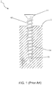
- a conventional fastener 1 comprises a head 11, a shank 12 extending downwards from the head 11, a drilling portion 13 connected to an end of the shank 12, and a threaded section 14 spirally disposed on the shank 12.
- a driving tool (not shown) is applied to rotate the head 11 to allow the drilling portion 13 which is rendered to touch a surface of an object 2 to start drilling.
- the drilling portion 13 drives the threaded section 14 to move downwards.
- the threaded section 14 contacts the object 2
- the threaded section 14 starts cutting the object 2 to thread the shank 12 into the object 2 to complete the screwing operation of the conventional fastener 1.
- the drilling portion 13 is rendered to press the object 2 firstly to carry out the movement of the threaded section 14.
- the threaded section 14 executes the cutting action of the object 2.
- the threaded section 14 is unable to break fibers of the object 2.
- the fibers of the object 2 cannot be severed effectively by the threaded section 14 to result in the entanglement of the fibers around the shank 12.
- the conventional fastener 1 keeps pressing the fibers while screwing into the object 2 to result in the enhanced drilling resistance and worsened screwing efficiency.
- cut chips produced by cutting the object 2 are excluded through the thread 14 inefficiently and further accumulate in the object 2.
- the accumulated cut chips cause the laborious screwing operation when the conventional fastener 1 keeps screwing into the object 2. Furthermore, the object 2 may crack when the conventional fastener 1 keeps moving downwards and squeezing the accumulated cut chips. Thus, the conventional fastener 1 still needs to be improved.
- the object of this invention is to provide a screw capable of reducing the drilling resistance to enhance the screwing efficiency.
- the screw of this invention comprises a head, a shank extending downwards therefrom, a drilling portion connected to an end of the shank and opposite to the head, a first threaded section spirally disposed around the shank, and a leading threaded section spirally extending upwards from the drilling portion.
- a disconnection of the first threaded section and the leading threaded section defines a valley.
- At least one cutting unit extending upwards from the valley is connected to the first threaded section and the leading threaded section respectively.
- a protruding height of the cutting unit is smaller than a distance defined from the shank to an outermost edge of the first threaded section.
- the cutting unit further positions and severs fibers which are not cut by the leading threaded section entirely. Therefore, the fibers will not hinder the screw from threading into the object. The friction between the first threaded section and the object is reduced effectively when the first threaded section continues cutting. Meanwhile, the fibers will not entwine around the shank to avoid slow drilling speed. Further, cut chips can be accommodated and excluded through the valley effectively to attain the smooth evacuation of the cut chips and enhance the accommodation effect of the cut chips. Whereby the drilling resistance is reduced and the engagement of the screw and the object is enhanced to increase the screwing efficiency.
- auxiliary cutting unit projecting from the valley.
- the shank has a second threaded section spiraled thereon.
- the second shank has a helical direction opposite to a helical direction of the first threaded section.
- the drilling portion has an auxiliary threaded section extending from the drilling portion and situated between the leading threaded section.
- the auxiliary threaded section has a helical direction opposite to a helical direction of the leading threaded section.
- the cutting unit has a positioning wall projecting outwards from the valley, a guiding wall connected to the positioning wall, and a cutting edge formed at a connection of the positioning wall and the guiding wall.
- the positioning wall has a vertical surface.
- the guiding wall has a surface slanting from the cutting edge to the valley.
- the first threaded section ends at a first end.
- the leading threaded section ends at a second end.
- Two ends of the cutting unit are respectively connected to the first end and the second end.
- the screw 3 includes a head 31, a shank 32 extending downwards from the head 31, a drilling portion 33 fitted at an end of the shank 32 and opposite to the head 31, a first threaded section 34 spiraled on the shank 32, and a leading threaded section 35 helically extending upwards from the drilling portion 33.
- the first threaded section 34 and the leading threaded section 35 are separated from each other to define a valley 321 between the first threaded section 34 and the leading threaded section 35.
- the first threaded section 34 is continuously disposed around the shank 32 and terminates at a first end 341, and the leading threaded section 35 is helically disposed on the length of the drilling portion 33 and terminates at a second end 351.
- the second end 351 may be located on the drilling portion 33 or on the shank 32.
- the valley 321 is formed between the ends 341, 351 of the first threaded section 34 and the leading threaded section 35. In other words, the valley 321 occupies a space between a last convolution of the first threaded section 34 and a last convolution of the leading threaded section 35.
- the valley 321 may extend to cover parts of the drilling portion 33. Or, the valley 321 can be elongated by adjusting the locations of the first end 341 and the second end 351 to allow the valley 321 to accommodate more cut chips.
- At least one cutting unit 36 projects from the valley 321. Two ends of the cutting unit 36 are respectively connected to the first end 341 of the first threaded section 34 and the second end 351 of the leading threaded section 35. Referring to Fig. 3 and Fig. 3A , a protruding height 36d of the cutting unit 36 is smaller than a distance 34d defined from the shank 32 to an outermost edge of the first threaded section 34.
- the cutting unit 36 has a positioning wall 361 protruding outwards from the valley 321, a guiding wall 362 connected to the positioning wall 361, and a cutting edge 363 formed at a convergence of the positioning wall 361 and the guiding wall 362.
- the positioning wall 361 has a vertical surface.
- the guiding wall has a surface inclining from the cutting edge 363 to the valley 321.
- the drilling portion 33 is positioned against to an object 4 firstly. Then, the head 31 receives the rotation force from a driving tool (not shown) to carry out the drilling action of the drilling portion 33 into the object 4 and synchronously drive the leading threaded section 35 to cut the object 4.
- the leading threaded section 35 assists the drilling portion 33 in reaming and cutting the object 4 at the beginning of the screwing operation to allow the screw 3 to thread into the object 4 quickly.
- the leading threaded section 35 can cut fibers of the object 4 roughly while threading into the object 4 gradually to prevent the drilling portion 33 from being entwined by the fibers.
- the cutting unit 36 continues to cut the object 4 thoroughly.
- the positioning wall 361 presses and positions the remained fibers which are not severed by the leading threaded section 35 to allow the cutting edge 363 to break the fibers completely.
- the severed fibers are then evacuated through the guiding wall 362 to be accommodated in the valley 321. Further, the valley 321 assists in accelerating the evacuation of the cut chips through the first threaded section 34 to the outside. Because the leading threaded section 35 and the cutting unit 36 execute the cutting action of the object 4 sequentially to attain the double cutting effect, the fibers are severed effectively.
- the fibers will not hinder the screw 3 from threading into the object 4, thereby facilitating the screwing operation, increasing the screwing speed, and reducing the drilling resistance caused by the accumulated cut chips.
- the cut chips can be evacuated along the valley 321 through the first threaded section 34 to the outside effectively, thereby achieving the smooth evacuation and preferable accommodation effect of the cut chips.
- the protruding height 36d is smaller than the distance 34d to prevent the cutting unit 36 from cutting the fibers of the object 4 beyond the limit. Meanwhile, the cutting unit 36 can press the fibers properly while threading into the object 4 to loosen the fibers and ream the object 4, thereby facilitating the following cutting and threading actions of the first threaded section 34.
- the screw 3 engages with the object 4 tightly.
- the screw 3 will not snap and the first threaded section 34 will not break during the screwing operation.
- the drilling resistance is reduced effectively.
- the cut chips are excluded smoothly to avoid slow drilling speed. Whereby the screwing efficiency is increased.
- FIG. 5 shows a second preferred embodiment of the screw 3 of this invention.
- the correlated elements and the concatenation of elements, the operation and objectives of the second preferred embodiment are the same as those of the first preferred embodiment.
- This embodiment is characterized in that at least one auxiliary cutting unit 37 projects from the valley 321. Two ends of the cutting unit 36 are still connected to the first end 341 and the second end 351 respectively. Contrarily, two ends of the auxiliary cutting unit 37 are disconnected from the first end 341 and the second end 351.
- the auxiliary cutting unit 37 assists the cutting unit 36 in cutting and reaming the object 4 at the beginning of the screwing operation, thereby accelerating the screwing operation.
- the screwing speed is increased.
- the drilling resistance is decreased greatly.
- the friction between the screw 3 and the object 4 is reduced greatly to attain the smooth and fast screwing operation. Further, the engagement of the screw 3 and the object 4 is enhanced to increase the screwing efficiency.
- FIG. 6 shows a third preferred embodiment of the screw 3 of this invention.
- the correlated elements and the concatenation of elements, the operation and objectives of the third preferred embodiment are the same as those of the first preferred embodiment.
- This embodiment is characterized in that the shank 32 has a second threaded section 38 helically formed on the shank 32 and situated between the first threaded section 34.
- the second threaded section 38 has a helical direction different from a helical direction of the first threaded section 34.
- the second threaded section 38 is helically disposed around the shank 32 and terminates at a third end 381. Meanwhile, the second threaded section 38 can be applied to different preferred embodiments.
- the second threaded section 38 can combine with the structure of the aforementioned second preferred embodiment and then the third end 381 of the second threaded section 38 connects to one end of the auxiliary cutting unit 37 to construct a fourth preferred embodiment shown in Fig. 7 .
- the set of alternating threaded sections namely the first threaded section 34 alternating with the second threaded section 38 accelerates the drilling and cutting actions and increases the evacuation of the cut chips, thereby reducing the drilling resistance greatly, preventing the cut chips from accumulating in the object 4 and achieving the smooth screwing operation.
- the engagement of the screw 3 and the object 4 is enhanced to increase screwing efficiency.
- FIG. 8 shows a fifth preferred embodiment of the screw 3 of this invention.
- the correlated elements and the concatenation of elements, the operation and objectives of the fifth preferred embodiment are the same as those of the first preferred embodiment.
- This embodiment is characterized in that the drilling portion 33 has an auxiliary threaded section 39 extending upwards from the drilling portion 33 and situated between the leading threaded section 35.
- the auxiliary threaded section 39 has a helical direction different from a helical direction of the leading threaded section 35.
- the auxiliary threaded section 39 is helically disposed on the length of the drilling portion 33 and terminates at a fourth end 391.
- the fourth end 391 may be located on the drilling portion 33 or on the shank 32.
- the auxiliary threaded section 39 can be applied to different preferred embodiments.
- the auxiliary threaded section 39 can combine with the structure of the aforementioned second preferred embodiment and then the fourth end 391 of the auxiliary threaded section 39 connects to one end of the auxiliary cutting unit 37 to construct a sixth preferred embodiment shown in Fig. 9 .
- the auxiliary threaded section 39 combines with the structure of the aforementioned third preferred embodiment to construct a seventh preferred embodiment shown in Fig. 10 wherein there are two sets of alternating threaded sections, namely the first threaded section 34 alternating with the second threaded section 38 and the leading threaded section 35 alternating with the auxiliary threaded section 39.
- a threaded section 34 alternating with the second threaded section 38 and the leading threaded section 35 alternating with the auxiliary threaded section 39
- two ends of the cutting unit 36 are respectively connected to the first end 341 of the first threaded section 34 and the second end 351 of the leading threaded section 35
- two ends of the auxiliary cutting unit 37 are respectively connected to the third end 381 of the second threaded section 38 and the fourth end 391 of the auxiliary threaded section 39.
- the set of alternating threaded sections namely the leading threaded section 35 alternating with the auxiliary threaded section 39 assists the drilling portion 33 in reaming and cutting the object 4 to increase the screwing speed of threading into the object 4 and reduce the drilling resistance at the beginning of the screwing operation. Whereby the screwing operation is facilitated and the tight engagement of the screw 3 and the object 4 is attained to achieve the better screwing efficiency.
- the screw of this invention takes advantages of the leading threaded section and at least one cutting unit which is connected to the first threaded section and the leading threaded section respectively to increase the screwing efficiency.
- the leading threaded section assists the drilling portion in cutting the fibers to prevent the drilling portion from being entwined by the fibers and reduce the drilling resistance at the beginning of the screwing operation.
- the cutting unit can position and sever the fibers which are not cut by the leading threaded section effectively to prevent the screwing operation from being hindered caused by the entanglement of the fibers around the shank.
- the friction between the screw and the object is reduced to accelerate the screwing operation.
- the screw engages with the object firmly and the drilling resistance is reduced greatly.
- the cut chips are accommodated and evacuated through the valley and the first threaded section smoothly. Whereby the preferable screwing efficiency is attained.
Landscapes
- Engineering & Computer Science (AREA)
- General Engineering & Computer Science (AREA)
- Mechanical Engineering (AREA)
- Physics & Mathematics (AREA)
- Geometry (AREA)
- Life Sciences & Earth Sciences (AREA)
- Chemical & Material Sciences (AREA)
- Dispersion Chemistry (AREA)
- Wood Science & Technology (AREA)
- Dowels (AREA)
Priority Applications (1)
| Application Number | Priority Date | Filing Date | Title |
|---|---|---|---|
| EP17196177.4A EP3366933B1 (fr) | 2017-10-12 | 2017-10-12 | Vis |
Applications Claiming Priority (1)
| Application Number | Priority Date | Filing Date | Title |
|---|---|---|---|
| EP17196177.4A EP3366933B1 (fr) | 2017-10-12 | 2017-10-12 | Vis |
Publications (2)
| Publication Number | Publication Date |
|---|---|
| EP3366933A1 true EP3366933A1 (fr) | 2018-08-29 |
| EP3366933B1 EP3366933B1 (fr) | 2020-04-22 |
Family
ID=60083814
Family Applications (1)
| Application Number | Title | Priority Date | Filing Date |
|---|---|---|---|
| EP17196177.4A Active EP3366933B1 (fr) | 2017-10-12 | 2017-10-12 | Vis |
Country Status (1)
| Country | Link |
|---|---|
| EP (1) | EP3366933B1 (fr) |
Citations (2)
| Publication number | Priority date | Publication date | Assignee | Title |
|---|---|---|---|---|
| US5015134A (en) * | 1989-09-12 | 1991-05-14 | Yamaki Sangyo Co., Ltd. | Tapping screw |
| US20060140738A1 (en) * | 2004-12-27 | 2006-06-29 | Teng-Hung Lin | Screw |
-
2017
- 2017-10-12 EP EP17196177.4A patent/EP3366933B1/fr active Active
Patent Citations (2)
| Publication number | Priority date | Publication date | Assignee | Title |
|---|---|---|---|---|
| US5015134A (en) * | 1989-09-12 | 1991-05-14 | Yamaki Sangyo Co., Ltd. | Tapping screw |
| US20060140738A1 (en) * | 2004-12-27 | 2006-06-29 | Teng-Hung Lin | Screw |
Also Published As
| Publication number | Publication date |
|---|---|
| EP3366933B1 (fr) | 2020-04-22 |
Similar Documents
| Publication | Publication Date | Title |
|---|---|---|
| EP3470692A1 (fr) | Vis à bois | |
| US12215728B2 (en) | Screw | |
| US10465731B2 (en) | Screw | |
| EP3460263B1 (fr) | Vis à vissage rapide | |
| EP3002468A1 (fr) | Vis auto-perceuse | |
| US8944734B2 (en) | Bimate screw | |
| US8740531B2 (en) | Screw | |
| US20200056647A1 (en) | Fastener | |
| US20110318137A1 (en) | Drilling fastener | |
| US20100061824A1 (en) | Screw | |
| EP3354913A1 (fr) | Structure pour vis auto-perceuse | |
| EP3366933B1 (fr) | Vis | |
| EP2444678B1 (fr) | Vis | |
| EP2077396B1 (fr) | Vis avec filetage double | |
| US11835077B2 (en) | Screw | |
| US20250180057A1 (en) | Screw | |
| EP3550160B1 (fr) | Pièce de fixation | |
| EP4134557B1 (fr) | Vis à angles de filetage multiples | |
| US20250188977A1 (en) | Versatile screw | |
| EP4484772A1 (fr) | Vis | |
| US20230048078A1 (en) | Screw with multiple thread angles | |
| JP5213836B2 (ja) | 木ねじ | |
| CN201884412U (zh) | 螺丝 | |
| EP4509730A1 (fr) | Dispositif de fixation | |
| US20250354577A1 (en) | Versatile fastener |
Legal Events
| Date | Code | Title | Description |
|---|---|---|---|
| PUAI | Public reference made under article 153(3) epc to a published international application that has entered the european phase |
Free format text: ORIGINAL CODE: 0009012 |
|
| STAA | Information on the status of an ep patent application or granted ep patent |
Free format text: STATUS: REQUEST FOR EXAMINATION WAS MADE |
|
| 17P | Request for examination filed |
Effective date: 20180723 |
|
| AK | Designated contracting states |
Kind code of ref document: A1 Designated state(s): AL AT BE BG CH CY CZ DE DK EE ES FI FR GB GR HR HU IE IS IT LI LT LU LV MC MK MT NL NO PL PT RO RS SE SI SK SM TR |
|
| AX | Request for extension of the european patent |
Extension state: BA ME |
|
| STAA | Information on the status of an ep patent application or granted ep patent |
Free format text: STATUS: EXAMINATION IS IN PROGRESS |
|
| 17Q | First examination report despatched |
Effective date: 20190703 |
|
| GRAP | Despatch of communication of intention to grant a patent |
Free format text: ORIGINAL CODE: EPIDOSNIGR1 |
|
| STAA | Information on the status of an ep patent application or granted ep patent |
Free format text: STATUS: GRANT OF PATENT IS INTENDED |
|
| INTG | Intention to grant announced |
Effective date: 20191126 |
|
| GRAJ | Information related to disapproval of communication of intention to grant by the applicant or resumption of examination proceedings by the epo deleted |
Free format text: ORIGINAL CODE: EPIDOSDIGR1 |
|
| STAA | Information on the status of an ep patent application or granted ep patent |
Free format text: STATUS: EXAMINATION IS IN PROGRESS |
|
| GRAJ | Information related to disapproval of communication of intention to grant by the applicant or resumption of examination proceedings by the epo deleted |
Free format text: ORIGINAL CODE: EPIDOSDIGR1 |
|
| GRAP | Despatch of communication of intention to grant a patent |
Free format text: ORIGINAL CODE: EPIDOSNIGR1 |
|
| GRAR | Information related to intention to grant a patent recorded |
Free format text: ORIGINAL CODE: EPIDOSNIGR71 |
|
| GRAS | Grant fee paid |
Free format text: ORIGINAL CODE: EPIDOSNIGR3 |
|
| STAA | Information on the status of an ep patent application or granted ep patent |
Free format text: STATUS: GRANT OF PATENT IS INTENDED |
|
| INTC | Intention to grant announced (deleted) | ||
| GRAA | (expected) grant |
Free format text: ORIGINAL CODE: 0009210 |
|
| STAA | Information on the status of an ep patent application or granted ep patent |
Free format text: STATUS: THE PATENT HAS BEEN GRANTED |
|
| INTG | Intention to grant announced |
Effective date: 20200312 |
|
| RAP1 | Party data changed (applicant data changed or rights of an application transferred) |
Owner name: TAIWAN SHAN YIN INTERNATIONAL CO., LTD. |
|
| RIN1 | Information on inventor provided before grant (corrected) |
Inventor name: SU, YU-JUNG Inventor name: SU, KOU-TSAIR |
|
| AK | Designated contracting states |
Kind code of ref document: B1 Designated state(s): AL AT BE BG CH CY CZ DE DK EE ES FI FR GB GR HR HU IE IS IT LI LT LU LV MC MK MT NL NO PL PT RO RS SE SI SK SM TR |
|
| REG | Reference to a national code |
Ref country code: CH Ref legal event code: EP |
|
| REG | Reference to a national code |
Ref country code: IE Ref legal event code: FG4D |
|
| REG | Reference to a national code |
Ref country code: DE Ref legal event code: R096 Ref document number: 602017015103 Country of ref document: DE |
|
| REG | Reference to a national code |
Ref country code: AT Ref legal event code: REF Ref document number: 1260495 Country of ref document: AT Kind code of ref document: T Effective date: 20200515 |
|
| REG | Reference to a national code |
Ref country code: SE Ref legal event code: TRGR |
|
| REG | Reference to a national code |
Ref country code: LT Ref legal event code: MG4D |
|
| REG | Reference to a national code |
Ref country code: NL Ref legal event code: MP Effective date: 20200422 |
|
| PG25 | Lapsed in a contracting state [announced via postgrant information from national office to epo] |
Ref country code: IS Free format text: LAPSE BECAUSE OF FAILURE TO SUBMIT A TRANSLATION OF THE DESCRIPTION OR TO PAY THE FEE WITHIN THE PRESCRIBED TIME-LIMIT Effective date: 20200822 Ref country code: GR Free format text: LAPSE BECAUSE OF FAILURE TO SUBMIT A TRANSLATION OF THE DESCRIPTION OR TO PAY THE FEE WITHIN THE PRESCRIBED TIME-LIMIT Effective date: 20200723 Ref country code: NO Free format text: LAPSE BECAUSE OF FAILURE TO SUBMIT A TRANSLATION OF THE DESCRIPTION OR TO PAY THE FEE WITHIN THE PRESCRIBED TIME-LIMIT Effective date: 20200722 Ref country code: FI Free format text: LAPSE BECAUSE OF FAILURE TO SUBMIT A TRANSLATION OF THE DESCRIPTION OR TO PAY THE FEE WITHIN THE PRESCRIBED TIME-LIMIT Effective date: 20200422 Ref country code: PT Free format text: LAPSE BECAUSE OF FAILURE TO SUBMIT A TRANSLATION OF THE DESCRIPTION OR TO PAY THE FEE WITHIN THE PRESCRIBED TIME-LIMIT Effective date: 20200824 Ref country code: NL Free format text: LAPSE BECAUSE OF FAILURE TO SUBMIT A TRANSLATION OF THE DESCRIPTION OR TO PAY THE FEE WITHIN THE PRESCRIBED TIME-LIMIT Effective date: 20200422 Ref country code: LT Free format text: LAPSE BECAUSE OF FAILURE TO SUBMIT A TRANSLATION OF THE DESCRIPTION OR TO PAY THE FEE WITHIN THE PRESCRIBED TIME-LIMIT Effective date: 20200422 |
|
| REG | Reference to a national code |
Ref country code: AT Ref legal event code: MK05 Ref document number: 1260495 Country of ref document: AT Kind code of ref document: T Effective date: 20200422 |
|
| PG25 | Lapsed in a contracting state [announced via postgrant information from national office to epo] |
Ref country code: BG Free format text: LAPSE BECAUSE OF FAILURE TO SUBMIT A TRANSLATION OF THE DESCRIPTION OR TO PAY THE FEE WITHIN THE PRESCRIBED TIME-LIMIT Effective date: 20200722 Ref country code: RS Free format text: LAPSE BECAUSE OF FAILURE TO SUBMIT A TRANSLATION OF THE DESCRIPTION OR TO PAY THE FEE WITHIN THE PRESCRIBED TIME-LIMIT Effective date: 20200422 Ref country code: LV Free format text: LAPSE BECAUSE OF FAILURE TO SUBMIT A TRANSLATION OF THE DESCRIPTION OR TO PAY THE FEE WITHIN THE PRESCRIBED TIME-LIMIT Effective date: 20200422 Ref country code: HR Free format text: LAPSE BECAUSE OF FAILURE TO SUBMIT A TRANSLATION OF THE DESCRIPTION OR TO PAY THE FEE WITHIN THE PRESCRIBED TIME-LIMIT Effective date: 20200422 |
|
| PG25 | Lapsed in a contracting state [announced via postgrant information from national office to epo] |
Ref country code: AL Free format text: LAPSE BECAUSE OF FAILURE TO SUBMIT A TRANSLATION OF THE DESCRIPTION OR TO PAY THE FEE WITHIN THE PRESCRIBED TIME-LIMIT Effective date: 20200422 |
|
| REG | Reference to a national code |
Ref country code: DE Ref legal event code: R097 Ref document number: 602017015103 Country of ref document: DE |
|
| PG25 | Lapsed in a contracting state [announced via postgrant information from national office to epo] |
Ref country code: AT Free format text: LAPSE BECAUSE OF FAILURE TO SUBMIT A TRANSLATION OF THE DESCRIPTION OR TO PAY THE FEE WITHIN THE PRESCRIBED TIME-LIMIT Effective date: 20200422 Ref country code: SM Free format text: LAPSE BECAUSE OF FAILURE TO SUBMIT A TRANSLATION OF THE DESCRIPTION OR TO PAY THE FEE WITHIN THE PRESCRIBED TIME-LIMIT Effective date: 20200422 Ref country code: EE Free format text: LAPSE BECAUSE OF FAILURE TO SUBMIT A TRANSLATION OF THE DESCRIPTION OR TO PAY THE FEE WITHIN THE PRESCRIBED TIME-LIMIT Effective date: 20200422 Ref country code: DK Free format text: LAPSE BECAUSE OF FAILURE TO SUBMIT A TRANSLATION OF THE DESCRIPTION OR TO PAY THE FEE WITHIN THE PRESCRIBED TIME-LIMIT Effective date: 20200422 Ref country code: RO Free format text: LAPSE BECAUSE OF FAILURE TO SUBMIT A TRANSLATION OF THE DESCRIPTION OR TO PAY THE FEE WITHIN THE PRESCRIBED TIME-LIMIT Effective date: 20200422 Ref country code: IT Free format text: LAPSE BECAUSE OF FAILURE TO SUBMIT A TRANSLATION OF THE DESCRIPTION OR TO PAY THE FEE WITHIN THE PRESCRIBED TIME-LIMIT Effective date: 20200422 Ref country code: CZ Free format text: LAPSE BECAUSE OF FAILURE TO SUBMIT A TRANSLATION OF THE DESCRIPTION OR TO PAY THE FEE WITHIN THE PRESCRIBED TIME-LIMIT Effective date: 20200422 Ref country code: ES Free format text: LAPSE BECAUSE OF FAILURE TO SUBMIT A TRANSLATION OF THE DESCRIPTION OR TO PAY THE FEE WITHIN THE PRESCRIBED TIME-LIMIT Effective date: 20200422 |
|
| PG25 | Lapsed in a contracting state [announced via postgrant information from national office to epo] |
Ref country code: PL Free format text: LAPSE BECAUSE OF FAILURE TO SUBMIT A TRANSLATION OF THE DESCRIPTION OR TO PAY THE FEE WITHIN THE PRESCRIBED TIME-LIMIT Effective date: 20200422 Ref country code: SK Free format text: LAPSE BECAUSE OF FAILURE TO SUBMIT A TRANSLATION OF THE DESCRIPTION OR TO PAY THE FEE WITHIN THE PRESCRIBED TIME-LIMIT Effective date: 20200422 |
|
| PLBE | No opposition filed within time limit |
Free format text: ORIGINAL CODE: 0009261 |
|
| STAA | Information on the status of an ep patent application or granted ep patent |
Free format text: STATUS: NO OPPOSITION FILED WITHIN TIME LIMIT |
|
| 26N | No opposition filed |
Effective date: 20210125 |
|
| PG25 | Lapsed in a contracting state [announced via postgrant information from national office to epo] |
Ref country code: SI Free format text: LAPSE BECAUSE OF FAILURE TO SUBMIT A TRANSLATION OF THE DESCRIPTION OR TO PAY THE FEE WITHIN THE PRESCRIBED TIME-LIMIT Effective date: 20200422 |
|
| REG | Reference to a national code |
Ref country code: CH Ref legal event code: PL |
|
| PG25 | Lapsed in a contracting state [announced via postgrant information from national office to epo] |
Ref country code: MC Free format text: LAPSE BECAUSE OF FAILURE TO SUBMIT A TRANSLATION OF THE DESCRIPTION OR TO PAY THE FEE WITHIN THE PRESCRIBED TIME-LIMIT Effective date: 20200422 Ref country code: LU Free format text: LAPSE BECAUSE OF NON-PAYMENT OF DUE FEES Effective date: 20201012 |
|
| REG | Reference to a national code |
Ref country code: BE Ref legal event code: MM Effective date: 20201031 |
|
| PG25 | Lapsed in a contracting state [announced via postgrant information from national office to epo] |
Ref country code: FR Free format text: LAPSE BECAUSE OF NON-PAYMENT OF DUE FEES Effective date: 20201031 |
|
| PG25 | Lapsed in a contracting state [announced via postgrant information from national office to epo] |
Ref country code: LI Free format text: LAPSE BECAUSE OF NON-PAYMENT OF DUE FEES Effective date: 20201031 Ref country code: CH Free format text: LAPSE BECAUSE OF NON-PAYMENT OF DUE FEES Effective date: 20201031 Ref country code: BE Free format text: LAPSE BECAUSE OF NON-PAYMENT OF DUE FEES Effective date: 20201031 |
|
| PG25 | Lapsed in a contracting state [announced via postgrant information from national office to epo] |
Ref country code: IE Free format text: LAPSE BECAUSE OF NON-PAYMENT OF DUE FEES Effective date: 20201012 |
|
| PG25 | Lapsed in a contracting state [announced via postgrant information from national office to epo] |
Ref country code: TR Free format text: LAPSE BECAUSE OF FAILURE TO SUBMIT A TRANSLATION OF THE DESCRIPTION OR TO PAY THE FEE WITHIN THE PRESCRIBED TIME-LIMIT Effective date: 20200422 Ref country code: MT Free format text: LAPSE BECAUSE OF FAILURE TO SUBMIT A TRANSLATION OF THE DESCRIPTION OR TO PAY THE FEE WITHIN THE PRESCRIBED TIME-LIMIT Effective date: 20200422 Ref country code: CY Free format text: LAPSE BECAUSE OF FAILURE TO SUBMIT A TRANSLATION OF THE DESCRIPTION OR TO PAY THE FEE WITHIN THE PRESCRIBED TIME-LIMIT Effective date: 20200422 |
|
| GBPC | Gb: european patent ceased through non-payment of renewal fee |
Effective date: 20211012 |
|
| PG25 | Lapsed in a contracting state [announced via postgrant information from national office to epo] |
Ref country code: MK Free format text: LAPSE BECAUSE OF FAILURE TO SUBMIT A TRANSLATION OF THE DESCRIPTION OR TO PAY THE FEE WITHIN THE PRESCRIBED TIME-LIMIT Effective date: 20200422 |
|
| PG25 | Lapsed in a contracting state [announced via postgrant information from national office to epo] |
Ref country code: GB Free format text: LAPSE BECAUSE OF NON-PAYMENT OF DUE FEES Effective date: 20211012 |
|
| PGFP | Annual fee paid to national office [announced via postgrant information from national office to epo] |
Ref country code: DE Payment date: 20251028 Year of fee payment: 9 |
|
| PGFP | Annual fee paid to national office [announced via postgrant information from national office to epo] |
Ref country code: SE Payment date: 20251024 Year of fee payment: 9 |