EP3368708B1 - Arbre avec dispositif de séparation - Google Patents
Arbre avec dispositif de séparation Download PDFInfo
- Publication number
- EP3368708B1 EP3368708B1 EP16788239.8A EP16788239A EP3368708B1 EP 3368708 B1 EP3368708 B1 EP 3368708B1 EP 16788239 A EP16788239 A EP 16788239A EP 3368708 B1 EP3368708 B1 EP 3368708B1
- Authority
- EP
- European Patent Office
- Prior art keywords
- spindle
- area
- clamping
- severing
- separating device
- Prior art date
- Legal status (The legal status is an assumption and is not a legal conclusion. Google has not performed a legal analysis and makes no representation as to the accuracy of the status listed.)
- Active
Links
Images


Classifications
-
- D—TEXTILES; PAPER
- D01—NATURAL OR MAN-MADE THREADS OR FIBRES; SPINNING
- D01H—SPINNING OR TWISTING
- D01H9/00—Arrangements for replacing or removing bobbins, cores, receptacles, or completed packages at paying-out or take-up stations ; Combination of spinning-winding machine
- D01H9/02—Arrangements for replacing or removing bobbins, cores, receptacles, or completed packages at paying-out or take-up stations ; Combination of spinning-winding machine for removing completed take-up packages and replacing by bobbins, cores, or receptacles at take-up stations; Transferring material between adjacent full and empty take-up elements
- D01H9/16—Yarn-severing arrangements, e.g. for cutting transfer tails; Separating of roving in flyer
Definitions
- the present invention relates to a spindle for a work station of a textile machine, in particular a ring spinning machine, according to the independent claim.
- the invention also relates to a separating device and a ring spinning machine with a plurality of work stations.
- Ring spinning spindles with a separating device for separating a spun yarn when a cop is pulled off are well known, for example from EP 911 434 B1 .
- the separating device is guided with a collar on the upper part of the spindle and fixed on the upper part of the spindle with a lug that falls behind a groove in the upper part of the spindle.
- this form of attachment requires a groove in the spindle upper part, which is known to have only a few special spindles. This separating device cannot be used for all other spindles.
- EP0292856A1 shows a top ring with a split area and a flange. This ring is disadvantageously attached to an upper end of the spindle base of the spindle, making the shank disadvantageously difficult to detach. A simple replacement of the cutting ring is not possible due to the attachment. The risk of injury for the operator is also relatively high due to the protruding teeth.
- DE2215251A1 discloses a ring with teeth and a slot that fits over a lower portion of a spool.
- the disadvantage is that the ring sits on the spool, ie each spool has to be equipped with it, which is a not inconsiderable cost factor.
- there is still a great risk of injury since the bobbins are frequently changed by the operator and the teeth can injure him when touching them.
- EP0458088A1 relates to a thread separating device for a spindle of a spinning or twisting machine with an annular body which sits between a sleeve receptacle of the spindle and a winding point of the spindle used to fix a spun thread and which has an edge protruding from the spindle in the radial direction, which has several acute-angled is provided with inwardly tapering notches, the edges of which are designed as cutting edges.
- the attachment to the shaft is done disadvantageously by a cover that is provided with internal locking lugs. Due to the protruding spikes, the risk of accidents should not be underestimated either.
- the object of the present invention is therefore to create a spindle with an associated separating device, in which case the separating device can be fastened to the shaft as simply as possible.
- the object is achieved by a spindle with a shaft and a separating device, a separating device and a ring spinning machine with a plurality of work stations, each having a spindle with a separating device, with the features of the independent claim.
- a spindle for a work station of a textile machine in particular a ring spinning machine, is proposed.
- the spindle has a shank for receiving a sleeve.
- a thread is wound onto the tube so that the tube becomes a cop.
- the spindle has a separating device. This separates the thread from the spindle when the cop is pulled off, so that the cop can be removed freely and the thread remaining on the textile machine can be wound onto a new tube.
- the separating device has a recess for enclosing the shaft so that it can lie around the shaft. An inner area adjoins this recess. Furthermore, the separating device has a separating area in which the thread is ultimately separated.
- the spindle has a spindle base adjacent to the shaft, the separating device is separate from the spindle base, ie an independent element, and the inner area of the separating device has at least one clamping area.
- the separating device is clamped to the shaft with this clamping area.
- the clamp firmly attaches the cutting device to the shaft of the spindle.
- the spindle does not need to have any special fastening device(s) since it can be clamped to a conventional shank.
- thanks to the clamp it is also easy to replace the separator, for example if it has become blunt.
- the at least one clamping area is circular.
- the diameter of the circular clamping area must be smaller than or equal to a diameter of the shank at a lower end of the shank where the separating device is usually attached. Since a circular clamping area clamps over the entire circumference of the spindle, a particularly strong attachment of the separating device is possible.
- the at least one clamping area that are not according to the invention are also possible. It is then advantageous if the diameter of a circle inscribed in the at least one clamping area, ie the largest circle that fits into the recess, is less than or equal to the diameter of the lower end of the shank. This ensures a strong clamping.
- the separating device has a slot.
- one end of the slot is arranged at the recess.
- the slit allows for greater deformation of the separating device, which in turn enables better clamping.
- a separating device not according to the invention can advantageously have a specially designed inner area which has three separate clamping areas. Clamping with these three clamping areas is also very effective. There is no need to attach a slot or it can be used in addition.
- the separating area has a circular edge, teeth and/or projections.
- the special design of the separating area can be adapted to the other features of the spindle, for example the geometry of a clamping crown, but also to the properties of the thread to be used.
- the separating device can advantageously be designed flat and rest on the spindle base. This is particularly advantageous since it is a space-saving variant.
- the circular edge, the spikes and/or projections are at least partially sharp.
- the thread can be separated even more easily with sharp elements.
- the separating device is designed in one piece. On the one hand, this enables the separating device to be produced cheaply and, on the other hand, it makes it more robust.
- the separating device is made of metal. This can be sanded without any problems, but also provides the elasticity required for clamping.
- the separating area has an outside diameter that is smaller than or equal to a diameter of the spindle base.
- the cutting area is set back behind the spindle base and the risk of injury to operating personnel, for example from cutting on sharp elements, is significantly reduced.
- the spindle base has indentations to better position the thread. It is then advantageous if the outside diameter of the separating area is greater than or equal to an inside diameter formed by the bases of the notches. Thus, the thread can come into contact with the cutting portion and be cut.
- the spindle base is a clamping crown. Shortly before the bobbin is to be removed, a few turns of the thread are wound onto the clamping crown and fixed there. If the cop is then removed from the spindle, the thread runs over the cutting area and is severed. With a corresponding design of the clamping crown, the separating device can also be clamped to this clamping crown.
- a ring spinning machine with a plurality of jobs has a spindle with a separating device for separating a thread when a cop is pulled off the spindle.
- the spindle is designed as described above.
- a separating device assigned to the spindle can be easily attached to the spindle and can also be easily replaced if it is blunt or another separating device tailored to a different thread is to be used.
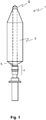
- figure 1 shows a side view of a spindle 1.
- a cop 3 Adjacent to the shank 2 of the spindle 1 is a clamping crown 4 is hardly visible here, but is designed flat and rests on the clamping crown 4.
- a cutting device, a cutting knife or the like is suitable as the separating device 5, as will be described in the following exemplary embodiments.
- Figure 2a shows the clamping crown 4 in more detail, in the open state, as it is just before the cop 3 is removed from the spindle 1.
- a clamping sleeve 6 was pulled down so that an underwind area 7 is open.
- a few windings of thread are now wound onto the underwind area 7 .
- the thread runs through notches in a clamping collar 8 and also over the separating device 5.
- Figure 3a shows a top view of the flat separating device 5 on the clamping collar 8.
- the diameter of a separating area 10 of the flat separating device 5 is smaller than the outer diameter of the clamping ring 8, which is advantageous for the operating personnel for safety reasons.
- the separating area 10 is a sharp edge or the like existing on the periphery, so that a cutting knife is formed.
- the separating device 5 protrudes beyond the notches 9 of the clamping collar 8, so that a thread located in a notch 9 can be separated.
- Figure 3b shows a top view of the separating device 5.
- the separating area 10 is sharpened here in order to enable better severing of the thread.
- the recess 11, which is delimited by the inner area 12 of the separating device 5, is circular in shape here, with a diameter which is slightly smaller than a diameter of the shank at the lower end of the shank. In this case the inner portion 12 is equal to the clamping portion 13. Due to the slot 14 in the separator 5, the separator 5 flexes slightly when pushed onto the shank and clamps the separator 5 firmly onto the shank.
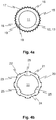
- Figure 4a shows a plan view of a further exemplary embodiment of a separating device 15.
- features which, in comparison to FIG Figure 3b illustrated first embodiment are identical and / or at least comparable in their design and / or mode of operation, the same reference numerals are used. If these are not explained again in detail, their design and/or mode of action corresponds to the design and mode of action of the features already described above.
- This separating device 15 differs in the design of the separating area 16. A large number of sharpened teeth 17 are provided here, which can reliably separate the thread.
- the slot 18 has two corners 19 . Should the thread be drawn into the slot, it will catch at the corners 19 and effectively prevent the thread from advancing to the shaft of the spindle.
- Figure 4b shows a plan view of a separating device 20 not according to the invention.
- features that are different from those in Figure 3b illustrated first embodiment are identical and / or at least comparable in their design and / or mode of operation, the same reference numerals are used. If these are not explained again in detail, their design and/or mode of action corresponds to the design and mode of action of the features already described above.
- projections 22 are provided for the separating area 21, which are sharpened on their sides 23.
- Such projections 22 are particularly suitable for separating threads when, after the cop has been lifted slightly from the spindle, the spindle is rotated again briefly. Then the thread is pulled past a sharpened side 23 and severed.
- the separating device 20 has a specially designed inner area 24 which has three separate clamping areas 25 . Clamping with these three clamping areas 25 is also very effective and there is no need to attach a slot.
Landscapes
- Engineering & Computer Science (AREA)
- Mechanical Engineering (AREA)
- Textile Engineering (AREA)
- Spinning Or Twisting Of Yarns (AREA)
Claims (10)
- Broche (1) pour un poste de travail d'une machine textile, en particulier d'un métier à filer à anneaux,• comprenant une tige (2) pour recevoir une douille, laquelle devient une canette (3) par enroulement d'un fil ;• une base de broche (4) adjacente à la tige (2) ; et• un dispositif de sectionnement (5, 15, 20) disposé au-dessus de la base de broche (4) pour sectionner le fil lors du retrait de la canette (3) de l'arbre (2) ;• dans laquelle le dispositif de sectionnement (5, 15, 20) comporte un évidement (11) pour entourer la tige (2), une zone intérieure (12, 24) adjacente à l'évidement (11) et une zone de sectionnement (10, 16, 21) ; et• le dispositif de sectionnement repose sur la base de broche (4) et n'y est pas relié, et• la zone intérieure (12, 24) du dispositif de sectionnement (5, 15, 20) comporte au moins une zone de serrage (13, 25) pour serrer le dispositif de sectionnement (5, 15, 20) sur la tige (2)caractérisée en ce que l'au moins une zone de serrage (13, 25) est circulaire et le diamètre de la zone de serrage (13) circulaire est inférieur ou égal à un diamètre d'une extrémité inférieure de la tige (2).
- Broche (1) selon la revendication précédente, caractérisée en ce que le dispositif de sectionnement (5, 15, 20) comporte une fente (14, 18) dont une extrémité est disposée au niveau de l'évidement (11).
- Broche (1) selon la revendication 2, caractérisée en ce que la fente (14, 18) comporte au moins un coin (19).
- Broche (1) selon l'une quelconque des revendications 1 à 3, caractérisée en ce que le dispositif de sectionnement (20) est réalisé plat.
- Broche (1) selon l'une quelconque des revendications 1 à 4, caractérisée en ce que la zone de sectionnement (10, 16, 21) comporte un bord circulaire, des dents (17) et/ou des saillies (22), lequel est ou lesquelles sont, de préférence au moins partiellement tranchant ou tranchantes.
- Broche (1) selon l'une quelconque des revendications 1 à 5, caractérisée en ce que le dispositif de sectionnement (5, 15, 20) est conçu monobloc, de préférence en métal.
- Broche (1) selon l'une quelconque des revendications 1 à 6, caractérisée en ce que la zone de sectionnement (10, 16, 21) présente un diamètre extérieur inférieur ou égal à un diamètre de la base de broche (4).
- Broche (1) selon la revendication 7, caractérisée en ce que la base de broche (4) comporte des encoches (9) et le diamètre extérieur de la zone de sectionnement (10, 16, 21) est supérieur ou égal à un diamètre intérieur formé par les bases des encoches (9).
- Broche (1) selon l'une quelconque des revendications 1 à 8, caractérisée en ce que la base de broche (4) est une couronne de serrage (4).
- Métier à filer à anneaux comportant une pluralité de postes de travail, dans lequel chaque poste de travail comporte une broche (1) dotée d'un dispositif de sectionnement (5, 15, 20) pour sectionner un fil lors du retrait d'une canette (3) de la broche (1), caractérisé en ce que la broche (1) est conçue selon l'au moins une quelconque des revendications 1 à 9.
Applications Claiming Priority (2)
| Application Number | Priority Date | Filing Date | Title |
|---|---|---|---|
| CH01571/15A CH711691A1 (de) | 2015-10-28 | 2015-10-28 | Spindel für eine Arbeitsstelle einer Textilmaschine mit einer Trennvorrichtung. |
| PCT/IB2016/056124 WO2017072619A1 (fr) | 2015-10-28 | 2016-10-13 | Dispositif de séparation |
Publications (2)
| Publication Number | Publication Date |
|---|---|
| EP3368708A1 EP3368708A1 (fr) | 2018-09-05 |
| EP3368708B1 true EP3368708B1 (fr) | 2022-01-12 |
Family
ID=57209661
Family Applications (1)
| Application Number | Title | Priority Date | Filing Date |
|---|---|---|---|
| EP16788239.8A Active EP3368708B1 (fr) | 2015-10-28 | 2016-10-13 | Arbre avec dispositif de séparation |
Country Status (4)
| Country | Link |
|---|---|
| EP (1) | EP3368708B1 (fr) |
| CN (1) | CN108138386B (fr) |
| CH (1) | CH711691A1 (fr) |
| WO (1) | WO2017072619A1 (fr) |
Families Citing this family (1)
| Publication number | Priority date | Publication date | Assignee | Title |
|---|---|---|---|---|
| DE102017103754A1 (de) | 2017-02-23 | 2018-08-23 | Maschinenfabrik Rieter Ag | Klemmvorrichtung, Spindel mit einer Klemmvorrichtung und Verfahren zum Herstellen einer Klemmvorrichtung |
Family Cites Families (6)
| Publication number | Priority date | Publication date | Assignee | Title |
|---|---|---|---|---|
| JPS5221782Y2 (fr) * | 1971-03-29 | 1977-05-19 | ||
| US4796422A (en) * | 1987-05-26 | 1989-01-10 | Odawara Industry Co., Ltd. | Apparatus for treating tail yarn in textile spindle assembly |
| DE4015707A1 (de) * | 1990-05-16 | 1991-11-21 | Zinser Textilmaschinen Gmbh | Fadentrenneinrichtung fuer eine spindel einer spinn- oder zwirnmaschine |
| DE4117704C2 (de) * | 1991-05-30 | 1995-05-18 | Zinser Textilmaschinen Gmbh | Abreißvorrichtung zum Abreißen von Garnen oder Zwirnen an einer Spinn- oder Zwirnmaschine |
| DE4436790C2 (de) * | 1994-10-14 | 1999-07-29 | Rieter Ag Maschf | Spinnstelle |
| DE19746536C2 (de) | 1997-10-22 | 2002-08-01 | Zinser Textilmaschinen Gmbh | Ringspinnspindel mit einem Trennmesser |
-
2015
- 2015-10-28 CH CH01571/15A patent/CH711691A1/de not_active Application Discontinuation
-
2016
- 2016-10-13 WO PCT/IB2016/056124 patent/WO2017072619A1/fr not_active Ceased
- 2016-10-13 EP EP16788239.8A patent/EP3368708B1/fr active Active
- 2016-10-13 CN CN201680061737.1A patent/CN108138386B/zh active Active
Non-Patent Citations (1)
| Title |
|---|
| None * |
Also Published As
| Publication number | Publication date |
|---|---|
| CN108138386A (zh) | 2018-06-08 |
| CN108138386B (zh) | 2022-07-19 |
| EP3368708A1 (fr) | 2018-09-05 |
| WO2017072619A1 (fr) | 2017-05-04 |
| CH711691A1 (de) | 2017-04-28 |
Similar Documents
| Publication | Publication Date | Title |
|---|---|---|
| EP2530041B1 (fr) | Dispositif de pince-fil pour une broche de filature ou de retordage | |
| DE2461621A1 (de) | Schneidvorrichtung fuer textilmaschinen | |
| CH188194A (de) | Kötzerspulmaschine mit einer Vorrichtung zum gleichzeitigen Aufstecken der leeren Spulenhülsen und zum Abnehmen der fertigen Kötzerspulen bei einer Mehrzahl von Spindeln. | |
| EP2832903B1 (fr) | Rotor de métiers à filer à bout libre doté d'une coupelle de rotor, d'un arbre de rotor et d'un dispositif de couplage | |
| EP0219738B1 (fr) | Support pour bobines | |
| EP3368708B1 (fr) | Arbre avec dispositif de séparation | |
| DE4436790C2 (de) | Spinnstelle | |
| EP3782942B1 (fr) | Armoire à bobines multiples destinée au bobinage d'un filament sur une bobine de transport et bobine tampon correspondante | |
| DE2544689C3 (de) | Spindel für Ringspinn- und Ringzwirnmaschinen, insbesondere für Cordzwirnmaschinen | |
| EP0458088B1 (fr) | Dispositif de sectionnement pour une broche d'un métier à filer ou à retordre | |
| DE1218916B (de) | Greifer zum Abziehen von Spinnkopsen an Ringspinnmaschinen, Zwirnmaschinen u. dgl. | |
| DE102012021231B3 (de) | Spulendorn mit einem Mutterelement für eine Korbspule für Draht | |
| DE19755972B4 (de) | Spinnvorrichtung | |
| EP3366820A1 (fr) | Dispositif de serrage, broche pourvue de dispositif de serrage et procédé de fabrication d'un dispositif de serrage | |
| DE3015207C1 (de) | Antriebswalze fuer Textilmaschinen | |
| DE2038654C3 (de) | An einer Spinnspindel befestigter Konus für Abfallgarn | |
| EP3257979A1 (fr) | Dispositif pince-fil | |
| DE7531710U (de) | Spindel mit unterwindkrone fuer ringspinn- und ringzwirnmaschinen, insbesondere fuer cordzwirnmaschinen | |
| DE202013104755U1 (de) | Spindelbremsenhalterung | |
| DE514228C (de) | Kupplungs-Einrichtung, insbesondere fuer die Streck- bzw. Lieferwalzen von Spinn-, Zwirn- und Spulmaschinen | |
| DE1760458A1 (de) | Verfahren zum Abtrennen von auf Spindeln unterwundenen Faeden und Spindel zur Durchfuehrung des Verfahrens | |
| DE2142637A1 (de) | Abfallgarnspule | |
| DE19820211C1 (de) | Vorrichtung zum Klemmen und Freigeben eines Unterwindefadens an der Spindel einer Ringspinn- und/oder -zwirnmaschine | |
| DE2220355C3 (de) | Spindel für Streckzwirnmaschinen | |
| EP3628759A1 (fr) | Griffe de peigne pourvue de boitier en deux parties |
Legal Events
| Date | Code | Title | Description |
|---|---|---|---|
| STAA | Information on the status of an ep patent application or granted ep patent |
Free format text: STATUS: UNKNOWN |
|
| STAA | Information on the status of an ep patent application or granted ep patent |
Free format text: STATUS: THE INTERNATIONAL PUBLICATION HAS BEEN MADE |
|
| PUAI | Public reference made under article 153(3) epc to a published international application that has entered the european phase |
Free format text: ORIGINAL CODE: 0009012 |
|
| STAA | Information on the status of an ep patent application or granted ep patent |
Free format text: STATUS: REQUEST FOR EXAMINATION WAS MADE |
|
| 17P | Request for examination filed |
Effective date: 20180522 |
|
| AK | Designated contracting states |
Kind code of ref document: A1 Designated state(s): AL AT BE BG CH CY CZ DE DK EE ES FI FR GB GR HR HU IE IS IT LI LT LU LV MC MK MT NL NO PL PT RO RS SE SI SK SM TR |
|
| AX | Request for extension of the european patent |
Extension state: BA ME |
|
| DAV | Request for validation of the european patent (deleted) | ||
| DAX | Request for extension of the european patent (deleted) | ||
| STAA | Information on the status of an ep patent application or granted ep patent |
Free format text: STATUS: EXAMINATION IS IN PROGRESS |
|
| 17Q | First examination report despatched |
Effective date: 20191202 |
|
| GRAP | Despatch of communication of intention to grant a patent |
Free format text: ORIGINAL CODE: EPIDOSNIGR1 |
|
| STAA | Information on the status of an ep patent application or granted ep patent |
Free format text: STATUS: GRANT OF PATENT IS INTENDED |
|
| INTG | Intention to grant announced |
Effective date: 20210810 |
|
| GRAS | Grant fee paid |
Free format text: ORIGINAL CODE: EPIDOSNIGR3 |
|
| GRAA | (expected) grant |
Free format text: ORIGINAL CODE: 0009210 |
|
| STAA | Information on the status of an ep patent application or granted ep patent |
Free format text: STATUS: THE PATENT HAS BEEN GRANTED |
|
| AK | Designated contracting states |
Kind code of ref document: B1 Designated state(s): AL AT BE BG CH CY CZ DE DK EE ES FI FR GB GR HR HU IE IS IT LI LT LU LV MC MK MT NL NO PL PT RO RS SE SI SK SM TR |
|
| REG | Reference to a national code |
Ref country code: GB Ref legal event code: FG4D Free format text: NOT ENGLISH |
|
| REG | Reference to a national code |
Ref country code: CH Ref legal event code: EP |
|
| REG | Reference to a national code |
Ref country code: DE Ref legal event code: R096 Ref document number: 502016014404 Country of ref document: DE |
|
| REG | Reference to a national code |
Ref country code: IE Ref legal event code: FG4D Free format text: LANGUAGE OF EP DOCUMENT: GERMAN |
|
| REG | Reference to a national code |
Ref country code: AT Ref legal event code: REF Ref document number: 1462449 Country of ref document: AT Kind code of ref document: T Effective date: 20220215 |
|
| REG | Reference to a national code |
Ref country code: LT Ref legal event code: MG9D |
|
| REG | Reference to a national code |
Ref country code: NL Ref legal event code: MP Effective date: 20220112 |
|
| PG25 | Lapsed in a contracting state [announced via postgrant information from national office to epo] |
Ref country code: NL Free format text: LAPSE BECAUSE OF FAILURE TO SUBMIT A TRANSLATION OF THE DESCRIPTION OR TO PAY THE FEE WITHIN THE PRESCRIBED TIME-LIMIT Effective date: 20220112 |
|
| PG25 | Lapsed in a contracting state [announced via postgrant information from national office to epo] |
Ref country code: SE Free format text: LAPSE BECAUSE OF FAILURE TO SUBMIT A TRANSLATION OF THE DESCRIPTION OR TO PAY THE FEE WITHIN THE PRESCRIBED TIME-LIMIT Effective date: 20220112 Ref country code: RS Free format text: LAPSE BECAUSE OF FAILURE TO SUBMIT A TRANSLATION OF THE DESCRIPTION OR TO PAY THE FEE WITHIN THE PRESCRIBED TIME-LIMIT Effective date: 20220112 Ref country code: PT Free format text: LAPSE BECAUSE OF FAILURE TO SUBMIT A TRANSLATION OF THE DESCRIPTION OR TO PAY THE FEE WITHIN THE PRESCRIBED TIME-LIMIT Effective date: 20220512 Ref country code: NO Free format text: LAPSE BECAUSE OF FAILURE TO SUBMIT A TRANSLATION OF THE DESCRIPTION OR TO PAY THE FEE WITHIN THE PRESCRIBED TIME-LIMIT Effective date: 20220412 Ref country code: LT Free format text: LAPSE BECAUSE OF FAILURE TO SUBMIT A TRANSLATION OF THE DESCRIPTION OR TO PAY THE FEE WITHIN THE PRESCRIBED TIME-LIMIT Effective date: 20220112 Ref country code: HR Free format text: LAPSE BECAUSE OF FAILURE TO SUBMIT A TRANSLATION OF THE DESCRIPTION OR TO PAY THE FEE WITHIN THE PRESCRIBED TIME-LIMIT Effective date: 20220112 Ref country code: ES Free format text: LAPSE BECAUSE OF FAILURE TO SUBMIT A TRANSLATION OF THE DESCRIPTION OR TO PAY THE FEE WITHIN THE PRESCRIBED TIME-LIMIT Effective date: 20220112 Ref country code: BG Free format text: LAPSE BECAUSE OF FAILURE TO SUBMIT A TRANSLATION OF THE DESCRIPTION OR TO PAY THE FEE WITHIN THE PRESCRIBED TIME-LIMIT Effective date: 20220412 |
|
| PG25 | Lapsed in a contracting state [announced via postgrant information from national office to epo] |
Ref country code: PL Free format text: LAPSE BECAUSE OF FAILURE TO SUBMIT A TRANSLATION OF THE DESCRIPTION OR TO PAY THE FEE WITHIN THE PRESCRIBED TIME-LIMIT Effective date: 20220112 Ref country code: LV Free format text: LAPSE BECAUSE OF FAILURE TO SUBMIT A TRANSLATION OF THE DESCRIPTION OR TO PAY THE FEE WITHIN THE PRESCRIBED TIME-LIMIT Effective date: 20220112 Ref country code: GR Free format text: LAPSE BECAUSE OF FAILURE TO SUBMIT A TRANSLATION OF THE DESCRIPTION OR TO PAY THE FEE WITHIN THE PRESCRIBED TIME-LIMIT Effective date: 20220413 Ref country code: FI Free format text: LAPSE BECAUSE OF FAILURE TO SUBMIT A TRANSLATION OF THE DESCRIPTION OR TO PAY THE FEE WITHIN THE PRESCRIBED TIME-LIMIT Effective date: 20220112 |
|
| PG25 | Lapsed in a contracting state [announced via postgrant information from national office to epo] |
Ref country code: IS Free format text: LAPSE BECAUSE OF FAILURE TO SUBMIT A TRANSLATION OF THE DESCRIPTION OR TO PAY THE FEE WITHIN THE PRESCRIBED TIME-LIMIT Effective date: 20220512 |
|
| REG | Reference to a national code |
Ref country code: DE Ref legal event code: R097 Ref document number: 502016014404 Country of ref document: DE |
|
| PG25 | Lapsed in a contracting state [announced via postgrant information from national office to epo] |
Ref country code: SM Free format text: LAPSE BECAUSE OF FAILURE TO SUBMIT A TRANSLATION OF THE DESCRIPTION OR TO PAY THE FEE WITHIN THE PRESCRIBED TIME-LIMIT Effective date: 20220112 Ref country code: SK Free format text: LAPSE BECAUSE OF FAILURE TO SUBMIT A TRANSLATION OF THE DESCRIPTION OR TO PAY THE FEE WITHIN THE PRESCRIBED TIME-LIMIT Effective date: 20220112 Ref country code: RO Free format text: LAPSE BECAUSE OF FAILURE TO SUBMIT A TRANSLATION OF THE DESCRIPTION OR TO PAY THE FEE WITHIN THE PRESCRIBED TIME-LIMIT Effective date: 20220112 Ref country code: EE Free format text: LAPSE BECAUSE OF FAILURE TO SUBMIT A TRANSLATION OF THE DESCRIPTION OR TO PAY THE FEE WITHIN THE PRESCRIBED TIME-LIMIT Effective date: 20220112 Ref country code: DK Free format text: LAPSE BECAUSE OF FAILURE TO SUBMIT A TRANSLATION OF THE DESCRIPTION OR TO PAY THE FEE WITHIN THE PRESCRIBED TIME-LIMIT Effective date: 20220112 Ref country code: CZ Free format text: LAPSE BECAUSE OF FAILURE TO SUBMIT A TRANSLATION OF THE DESCRIPTION OR TO PAY THE FEE WITHIN THE PRESCRIBED TIME-LIMIT Effective date: 20220112 |
|
| PLBE | No opposition filed within time limit |
Free format text: ORIGINAL CODE: 0009261 |
|
| STAA | Information on the status of an ep patent application or granted ep patent |
Free format text: STATUS: NO OPPOSITION FILED WITHIN TIME LIMIT |
|
| PG25 | Lapsed in a contracting state [announced via postgrant information from national office to epo] |
Ref country code: AL Free format text: LAPSE BECAUSE OF FAILURE TO SUBMIT A TRANSLATION OF THE DESCRIPTION OR TO PAY THE FEE WITHIN THE PRESCRIBED TIME-LIMIT Effective date: 20220112 |
|
| 26N | No opposition filed |
Effective date: 20221013 |
|
| PG25 | Lapsed in a contracting state [announced via postgrant information from national office to epo] |
Ref country code: SI Free format text: LAPSE BECAUSE OF FAILURE TO SUBMIT A TRANSLATION OF THE DESCRIPTION OR TO PAY THE FEE WITHIN THE PRESCRIBED TIME-LIMIT Effective date: 20220112 |
|
| PG25 | Lapsed in a contracting state [announced via postgrant information from national office to epo] |
Ref country code: MC Free format text: LAPSE BECAUSE OF FAILURE TO SUBMIT A TRANSLATION OF THE DESCRIPTION OR TO PAY THE FEE WITHIN THE PRESCRIBED TIME-LIMIT Effective date: 20220112 |
|
| REG | Reference to a national code |
Ref country code: CH Ref legal event code: PL |
|
| REG | Reference to a national code |
Ref country code: BE Ref legal event code: MM Effective date: 20221031 |
|
| GBPC | Gb: european patent ceased through non-payment of renewal fee |
Effective date: 20221013 |
|
| P01 | Opt-out of the competence of the unified patent court (upc) registered |
Effective date: 20230519 |
|
| PG25 | Lapsed in a contracting state [announced via postgrant information from national office to epo] |
Ref country code: LU Free format text: LAPSE BECAUSE OF NON-PAYMENT OF DUE FEES Effective date: 20221013 |
|
| PG25 | Lapsed in a contracting state [announced via postgrant information from national office to epo] |
Ref country code: LI Free format text: LAPSE BECAUSE OF NON-PAYMENT OF DUE FEES Effective date: 20221031 Ref country code: IT Free format text: LAPSE BECAUSE OF FAILURE TO SUBMIT A TRANSLATION OF THE DESCRIPTION OR TO PAY THE FEE WITHIN THE PRESCRIBED TIME-LIMIT Effective date: 20220112 Ref country code: FR Free format text: LAPSE BECAUSE OF NON-PAYMENT OF DUE FEES Effective date: 20221031 Ref country code: CH Free format text: LAPSE BECAUSE OF NON-PAYMENT OF DUE FEES Effective date: 20221031 |
|
| PG25 | Lapsed in a contracting state [announced via postgrant information from national office to epo] |
Ref country code: BE Free format text: LAPSE BECAUSE OF NON-PAYMENT OF DUE FEES Effective date: 20221031 |
|
| PG25 | Lapsed in a contracting state [announced via postgrant information from national office to epo] |
Ref country code: IE Free format text: LAPSE BECAUSE OF NON-PAYMENT OF DUE FEES Effective date: 20221013 Ref country code: GB Free format text: LAPSE BECAUSE OF NON-PAYMENT OF DUE FEES Effective date: 20221013 |
|
| REG | Reference to a national code |
Ref country code: AT Ref legal event code: MM01 Ref document number: 1462449 Country of ref document: AT Kind code of ref document: T Effective date: 20221013 |
|
| PG25 | Lapsed in a contracting state [announced via postgrant information from national office to epo] |
Ref country code: AT Free format text: LAPSE BECAUSE OF NON-PAYMENT OF DUE FEES Effective date: 20221013 |
|
| PG25 | Lapsed in a contracting state [announced via postgrant information from national office to epo] |
Ref country code: HU Free format text: LAPSE BECAUSE OF FAILURE TO SUBMIT A TRANSLATION OF THE DESCRIPTION OR TO PAY THE FEE WITHIN THE PRESCRIBED TIME-LIMIT; INVALID AB INITIO Effective date: 20161013 |
|
| PG25 | Lapsed in a contracting state [announced via postgrant information from national office to epo] |
Ref country code: CY Free format text: LAPSE BECAUSE OF FAILURE TO SUBMIT A TRANSLATION OF THE DESCRIPTION OR TO PAY THE FEE WITHIN THE PRESCRIBED TIME-LIMIT Effective date: 20220112 |
|
| PG25 | Lapsed in a contracting state [announced via postgrant information from national office to epo] |
Ref country code: MK Free format text: LAPSE BECAUSE OF FAILURE TO SUBMIT A TRANSLATION OF THE DESCRIPTION OR TO PAY THE FEE WITHIN THE PRESCRIBED TIME-LIMIT Effective date: 20220112 |
|
| PG25 | Lapsed in a contracting state [announced via postgrant information from national office to epo] |
Ref country code: MT Free format text: LAPSE BECAUSE OF FAILURE TO SUBMIT A TRANSLATION OF THE DESCRIPTION OR TO PAY THE FEE WITHIN THE PRESCRIBED TIME-LIMIT Effective date: 20220112 |
|
| PGFP | Annual fee paid to national office [announced via postgrant information from national office to epo] |
Ref country code: DE Payment date: 20251020 Year of fee payment: 10 |
|
| PGFP | Annual fee paid to national office [announced via postgrant information from national office to epo] |
Ref country code: TR Payment date: 20251006 Year of fee payment: 10 |