EP3628759A1 - Griffe de peigne pourvue de boitier en deux parties - Google Patents
Griffe de peigne pourvue de boitier en deux parties Download PDFInfo
- Publication number
- EP3628759A1 EP3628759A1 EP19197839.4A EP19197839A EP3628759A1 EP 3628759 A1 EP3628759 A1 EP 3628759A1 EP 19197839 A EP19197839 A EP 19197839A EP 3628759 A1 EP3628759 A1 EP 3628759A1
- Authority
- EP
- European Patent Office
- Prior art keywords
- holding element
- membrane
- gripper
- wall
- coil
- Prior art date
- Legal status (The legal status is an assumption and is not a legal conclusion. Google has not performed a legal analysis and makes no representation as to the accuracy of the status listed.)
- Granted
Links
Images
Classifications
-
- D—TEXTILES; PAPER
- D01—NATURAL OR MAN-MADE THREADS OR FIBRES; SPINNING
- D01H—SPINNING OR TWISTING
- D01H9/00—Arrangements for replacing or removing bobbins, cores, receptacles, or completed packages at paying-out or take-up stations ; Combination of spinning-winding machine
- D01H9/02—Arrangements for replacing or removing bobbins, cores, receptacles, or completed packages at paying-out or take-up stations ; Combination of spinning-winding machine for removing completed take-up packages and replacing by bobbins, cores, or receptacles at take-up stations; Transferring material between adjacent full and empty take-up elements
- D01H9/04—Doffing arrangements integral with spinning or twisting machines
-
- B—PERFORMING OPERATIONS; TRANSPORTING
- B65—CONVEYING; PACKING; STORING; HANDLING THIN OR FILAMENTARY MATERIAL
- B65H—HANDLING THIN OR FILAMENTARY MATERIAL, e.g. SHEETS, WEBS, CABLES
- B65H67/00—Replacing or removing cores, receptacles, or completed packages at paying-out, winding, or depositing stations
- B65H67/04—Arrangements for removing completed take-up packages and or replacing by cores, formers, or empty receptacles at winding or depositing stations; Transferring material between adjacent full and empty take-up elements
-
- B—PERFORMING OPERATIONS; TRANSPORTING
- B65—CONVEYING; PACKING; STORING; HANDLING THIN OR FILAMENTARY MATERIAL
- B65H—HANDLING THIN OR FILAMENTARY MATERIAL, e.g. SHEETS, WEBS, CABLES
- B65H67/00—Replacing or removing cores, receptacles, or completed packages at paying-out, winding, or depositing stations
- B65H67/02—Arrangements for removing spent cores or receptacles and replacing by supply packages at paying-out stations
-
- B—PERFORMING OPERATIONS; TRANSPORTING
- B65—CONVEYING; PACKING; STORING; HANDLING THIN OR FILAMENTARY MATERIAL
- B65H—HANDLING THIN OR FILAMENTARY MATERIAL, e.g. SHEETS, WEBS, CABLES
- B65H67/00—Replacing or removing cores, receptacles, or completed packages at paying-out, winding, or depositing stations
- B65H67/06—Supplying cores, receptacles, or packages to, or transporting from, winding or depositing stations
- B65H67/064—Supplying or transporting cross-wound packages, also combined with transporting the empty core
- B65H67/065—Manipulators with gripping or holding means for transferring the packages from one station to another, e.g. from a conveyor to a creel trolley
-
- D—TEXTILES; PAPER
- D01—NATURAL OR MAN-MADE THREADS OR FIBRES; SPINNING
- D01H—SPINNING OR TWISTING
- D01H9/00—Arrangements for replacing or removing bobbins, cores, receptacles, or completed packages at paying-out or take-up stations ; Combination of spinning-winding machine
- D01H9/001—Bobbin-taking arrangements
- D01H9/003—Graspers operating under the action of a fluid
-
- B—PERFORMING OPERATIONS; TRANSPORTING
- B65—CONVEYING; PACKING; STORING; HANDLING THIN OR FILAMENTARY MATERIAL
- B65H—HANDLING THIN OR FILAMENTARY MATERIAL, e.g. SHEETS, WEBS, CABLES
- B65H2701/00—Handled material; Storage means
- B65H2701/30—Handled filamentary material
- B65H2701/31—Textiles threads or artificial strands of filaments
Definitions
- the invention relates to a gripper for gripping a coil or coil sleeve and to a holding element for such a gripper according to the preamble of the independent claims. It also relates to a doffer comprising a doffer bar with at least one gripper according to the invention and to a ring spinning machine with such a doffer.
- the spinning machines have a doffer device with a doffer bar, which is arranged, for example, movably on the spinning machine via a scissor mechanism.
- a large number of grippers or doffer grippers are in turn arranged on the doffer bar in order to be able to grip and remove or attach the coils or the empty bobbin tubes together.
- the individual grippers can preferably be actuated pneumatically and contain a clamping element in the form of a membrane which can be pressurized with air, which is brought over the coil or coil sleeve and then grips the coil or coil sleeve by introducing compressed air.
- compressed air supply channels are arranged in the doffer bar, from which the compressed air is fed via feeds to the individual membranes of the grippers.
- the CN2873813Y describes an appropriately trained gripper.
- the gripper has a cylindrical holding element for receiving a coil or coil sleeve.
- a clamping element in the form of a rubber membrane is arranged on the inner wall of the holding element and can be adjusted via a pneumatic device. With the Membrane, it is possible to grasp the end region of the coil or coil sleeve inserted into the interior of the holding element from the outside.
- the membrane is fixed in the direction of a longitudinal axis on the holding element via two sealing caps, which are each arranged on the underside and top of the holding element. The two caps are clipped onto the holding element via a snap connection.
- the gripper comprises a fastening element for fastening to a doffer bar.
- the fastening element is firmly connected to the holding element and contains an air channel for the compressed air supply to the membrane.
- the fastening element has a hook on its upper side and an elastic holding tab on its lower side.
- the gripper is fixed to a holder via the hook and in a snap-in groove on the doffer bar via the elastic retaining tab.
- a similarly designed gripper is in the EP0303877A1 shown.
- the fastening element of the gripper has an elastic holding tab on its underside and on its top.
- the gripper can be disengaged and releasably attached to the doffer bar in two parallel locking grooves using the two elastic retaining tabs.
- the locking grooves allow a plurality of individual grippers to be attached along the doffer bar.
- the membrane When changing a coil or coil sleeve, the membrane is pressurized with compressed air via the air duct. As a result, the membrane contracts in the holding element and grasps the coil or coil sleeve at its end region from the outside. In order to release the coil or coil sleeve in the holding element again, the membrane is relieved by removing the compressed air. Due to the constantly changing load and relief of the membrane, and the friction of the membrane on the coil or coil sleeve, the membrane wears out after a certain operating time. The wear shows up in the fact that the membrane becomes porous and has leaks. As a result, a safe change of the coil or coil sleeve is no longer guaranteed. It is therefore necessary to replace the worn membrane with a new membrane after a certain period of operation.
- a major disadvantage of the gripper described is that the exchange of a worn membrane for a new membrane is very complex.
- the gripper To replace a membrane, the gripper must first be removed from the doffer bar by the operating personnel.
- the CN2873813Y the hook is released from the holder of the doffing bar and the elastic retaining tab is released from the locking groove or from the gripper EP0303877A1 the two elastic retaining tabs are released from the two parallel locking grooves.
- the upper and lower closure caps are then released from the holding element.
- the worn membrane is then separated from the holding element and replaced with a new membrane.
- the new membrane is then fixed again in the direction of the longitudinal axis of the holding element on the holding element by the closure caps and the gripper is attached to the doffing bar. Due to the structure of the gripper, the replacement of a worn membrane is very complex, since the entire gripper must be removed from the doffer bar. Replacing the membrane is therefore associated with long downtimes of the spinning machine. In addition, due to the frequent assembly and disassembly of the gripper on the doffer bar, there is unnecessary wear on the elastic holding tab of the gripper. As a result, a sufficient clamping effect of the elastic retaining tab in the locking groove on the doffer bar is not ensured.
- a gripper for gripping a coil or coil sleeve with a fastening element and a cylindrical holding element with a longitudinal axis in front the holding element having an inner wall and an outer wall, and on the inner wall a pneumatically actuated clamping element is arranged, which can be acted upon with compressed air via an air duct.
- a securing element the securing element partially enclosing the outer wall of the holding element.
- the gripper is made of plastic and has a cylindrical holding element for a coil or a coil sleeve.
- the holding element has an inner wall on which a pneumatically adjustable clamping element in the form of a membrane made of rubber is arranged.
- a pneumatically adjustable clamping element in the form of a membrane made of rubber is arranged.
- a sealing ring is arranged in the membrane and the fastening element and the securing element.
- the invention has for its object to provide a gripper for gripping a coil or coil sleeve with a holding element, which is characterized by a better sealing effect than the grippers known from the prior art.
- the invention is further based on the object of providing a gripper for gripping a coil or coil sleeve with a holding element which is distinguished by a shortened gripping time of the doffer.
- the invention is further based on the object of providing a gripper for gripping a coil or coil sleeve with a holding element which is distinguished by simplified production.
- a gripper for gripping a coil or coil sleeve and a holding element according to the preamble of the independent claims, which are characterized in that the membrane is integrally connected with a lower and / or upper edge of the holding element.
- the holding element advantageously has a lower and / or upper shoulder as an edge, the membrane being integrally connected to the lower and / or upper shoulder.
- the membrane can be integrally connected to one another only with a lower shoulder as the edge of the holding element.
- a cover is located at the upper end of the holding element, around which the membrane is guided. The edge of the lid slightly overlaps the edge of the holding element.
- the material connection between the holding element and the membrane can preferably be achieved by gluing, welding, vulcanizing or in another suitable manner.
- a groove can advantageously be formed on the security element and on the fastening element by a projection into which the shoulder of the holding element can be inserted. Furthermore, the cover can form an upper fixation of the holding element together with the upper edge of the securing element and the upper edge of the fastening element. For this purpose, the edges mentioned are bent inwards. In this way, a definite and secure hold of the holding element between the security element and the fastening element is ensured.
- the holding element can advantageously be cylindrical or tapered towards the top.
- the air duct can advantageously be arranged on the side of the outer wall or guided upwards on the outer wall. In this way, the holding element can be used in a variety of ways in different grips.
- the holding element can then be removed as a unit and exchanged as a whole.
- the downtime of the spinning machine during the exchange of a membrane is thereby kept to a minimum.
- Another advantage of the holding element is that it is compactly constructed as a unit and, due to the integral connection, it has a better sealing effect compared to the holding elements embodied in the prior art distinguished. Due to the conical design of the holding element, a secure hold of the coil or coil sleeve and a shorter gripping time of the doffer can advantageously also be achieved.
- the invention also relates to a doffer comprising a doffer bar with at least one gripper according to the invention and to a spinning machine with such a doffer.
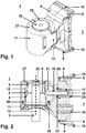
- Fig. 1 shows a perspective view of a gripper 1 and Fig. 2 a longitudinal section through the gripper 1 according to Fig. 1 .
- the gripper 1 is made of plastic and has an upwardly tapered holding element 2 for a coil or coil sleeve 3.
- the holding element 2 has an inner wall 4, on which a pneumatically adjustable clamping element in the form of a membrane 5 made of rubber is arranged. With the membrane 5, it is possible to end the area in the interior of the holding element 2 inserted coil or coil sleeve 3 to be detected from the outside.
- the diaphragm 5 is adjusted in the direction of the double arrow 6 via a pneumatic device.
- the gripper 1 comprises a fastening element 7, as is known from the document WO2016059496 is known.
- the fastening element 7 comprises two elastic holding tabs 8 arranged at a distance from one another and a rigid support element arranged between the elastic holding tabs, the two elastic holding tabs 8 being connected to the fastening element 7 by a first end 9 and each by at least one second free end 10 a spring element are positioned in a rest position. With the second free end 10, the gripper 1 can be disengaged and detachably attached to the doffer bar. It is provided that the at least one spring element is formed in one piece with the free end 9, 10 of the respective elastic retaining tab 8 and the rigid support element.
- the holding element 2 is held on the fastening element 7 via a securing element 11.
- the securing element 11 encloses at least 180 ° of an outer wall 12 of the holding element 2.
- the securing element 11 thus forms part of the housing of the gripper 1 in addition to the fastening element 7.
- Via the securing element 11, the holding element 2 is secured to the fastening element 7 transversely to a longitudinal axis 13 .
- the securing element 11 is detachably connected to the fastening element 7 via a snap connection.
- the snap connection is designed such that the fastening element 7 elevations and the securing element 14 has two lateral tabs 14 with depressions which enclose the elevations or into which the elevations engage, as is the case, for example, in FIG Fig. 5 of the WO2016071789 is known.
- the fastening element 7 is fixedly connected to the holding element 2 and contains an air channel 16 for the compressed air supply to the membrane 5.
- the air channel 16 is connected to a compressed air line which extends in the longitudinal direction on the doffing bar.
- the air duct 16 is opposite the doffer bar via a first one on the fastening element 7 arranged sealing element 17 sealed.
- the sealing element 17 is designed as a sleeve made of rubber.
- the fastening element 7 also has a second sealing element 18, which seals the gripper 1 against a compressed air signal line, which likewise extends in the longitudinal direction on the doffer bar.
- the air duct 16 is firmly connected to the outer wall 12 of the holding element 2, i.e. the holding element 2 and the air duct 16 are formed in one piece.
- the air duct 16 has an annular shoulder 20 on its outer surface 19.
- the shoulder 19 extends over a length of 8 mm of the air duct 16 and is made of an elastic plastic.
- the shoulder 19 is integrally connected to the air duct 16.
- the fastening element 11 has a receptacle 21 for the air duct 12.
- the receptacle 21 is cylindrical and extends over the length of the air duct 16.
- the holding element 2 is loosely connected to the fastening element 7 via the shoulder 20 of the air duct 16. With a first end 22, the sealing element 17 lies against the annular shoulder 20 of the air duct 16.
- the sealing element 13 seals the air duct 12 from the compressed air line on the doffer bar. If compressed air is applied to the membrane 5, the air channel 16 expands in the radial direction in the receptacle 20. As a result, the shoulder 20 is pressed against the fastening element 11 and seals the air duct 16 with respect to the fastening element 7.
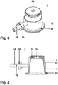
- Fig. 3 shows a perspective view of a holding element 2 and Fig. 4 a longitudinal section through the holding element 2 according to Fig. 3 .
- the holding element 2 tapers upwards with a step in the middle.
- the holding element 2 is preferably produced from an injection molding process.
- the membrane 5 can be glued, welded, vulcanized or cohesively connected in another suitable manner to the underside of the shoulder 24.
- a plastic laser welding process can preferably be used for this purpose.
- the holding element 2 can consist of a laser-absorbing material such as polyamide 6, and the membrane 5 can consist of a laser-permeable material such as a thermoplastic polyurethane (TPU).
- TPU thermoplastic polyurethane
- the edge of the cover 25 slightly overlaps the edge of the holding element 2 and the membrane 5 is guided between the holding element 2 and the cover 25 and around the cover 25.
- the membrane 5 is pulled down and tensioned between the holding element 2 and the cover 25 for a good sealing effect, so that the cover 25 is pressed onto the holding element 2.
- the membrane 5 is joined to the shoulder 24, glued or welded.
- the holding element 2 designed in this way is introduced between the securing element 11 and the fastening element 7, the annular shoulder 20 being inserted into the receptacle 21 (cf. Fig. 2 ).
- the shoulder 24 of the holding element 2 is inserted into the groove which is located below the rib 26.
- the upper edge 27 of the securing element 11 and the upper edge 28 of the fastening element 7 together with the cover 25 form the upper fixation.
- the mentioned edges 27, 28 are bent inwards, lie on the holding element 2 next to the cover 25 and are positively connected (cf. Fig. 1 ).
- the holding element 2 is tapered with a step in the embodiment shown, it can also have a different shape. It could be tapered upwards without a step or also cylindrical (not shown). According to a further embodiment, not shown, it would be conceivable to provide a shoulder at the upper end and also to weld the membrane 5 to the upper shoulder.
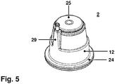
- Fig. 5 a perspective view of a second embodiment of a holding element 2 according to the invention.
- the holding element 2 is the same as that in FIG 3, 4 shown holding element 2 constructed, but has an upwardly directed air channel 29 with a plug that protrudes beyond the cover 25 and is connected there to a corresponding compressed air line.
- the air duct 29 is part of the upper section of the outer wall 12 and is integrated into the outer wall.
- This embodiment is, for example, for a double gripper like it is made of 2a, b or Fig. 5 of the WO2017085588 has become known.
- the holding element 2 is compactly constructed as a unit and is characterized by the material connection by a better sealing effect compared to the holding elements embodied in the prior art. Due to the conical design of the holding element, a secure hold of the coil or coil sleeve 3 and a shortened gripping time of the doffer can advantageously also be achieved.
Landscapes
- Engineering & Computer Science (AREA)
- Mechanical Engineering (AREA)
- Textile Engineering (AREA)
- Separation Using Semi-Permeable Membranes (AREA)
- Spinning Or Twisting Of Yarns (AREA)
Applications Claiming Priority (1)
| Application Number | Priority Date | Filing Date | Title |
|---|---|---|---|
| CH01178/18A CH715389A1 (de) | 2018-09-27 | 2018-09-27 | Greifer zum Greifen einer Spule oder Spulenhülse. |
Publications (3)
| Publication Number | Publication Date |
|---|---|
| EP3628759A1 true EP3628759A1 (fr) | 2020-04-01 |
| EP3628759B1 EP3628759B1 (fr) | 2024-08-07 |
| EP3628759B8 EP3628759B8 (fr) | 2024-09-18 |
Family
ID=67997381
Family Applications (1)
| Application Number | Title | Priority Date | Filing Date |
|---|---|---|---|
| EP19197839.4A Active EP3628759B8 (fr) | 2018-09-27 | 2019-09-17 | Dispositif de levée pourvu d'un boitier en deux parties |
Country Status (4)
| Country | Link |
|---|---|
| EP (1) | EP3628759B8 (fr) |
| KR (1) | KR102727272B1 (fr) |
| CN (1) | CN110952177A (fr) |
| CH (1) | CH715389A1 (fr) |
Citations (8)
| Publication number | Priority date | Publication date | Assignee | Title |
|---|---|---|---|---|
| CH557777A (de) * | 1972-04-28 | 1975-01-15 | Zinser Textilmaschinen Gmbh | Greifvorrichtung. |
| DE3214128A1 (de) * | 1982-04-16 | 1983-10-27 | Schubert & Salzer Maschinenfabrik Ag, 8070 Ingolstadt | Pneumatischer greifer |
| EP0303877A1 (fr) | 1987-08-18 | 1989-02-22 | Maschinenfabrik Rieter Ag | Dispositif pour remplacer en commun des tubes de bobines d'une machine textile, en particulier d'un continu à filer à anneaux |
| CN2873813Y (zh) | 2006-01-04 | 2007-02-28 | 东台纺织机械有限责任公司 | 细纱机集体落纱装置的握纱器 |
| CN200992611Y (zh) * | 2007-01-05 | 2007-12-19 | 铜陵市松宝机械有限公司 | 用于细纱机的抓管器 |
| WO2016059496A1 (fr) | 2014-10-16 | 2016-04-21 | Maschinenfabrik Rieter Ag | Fixation de griffe de peigneur |
| WO2016071789A1 (fr) | 2014-11-03 | 2016-05-12 | Maschinenfabrik Rieter Ag | Griffe de leveuse comprenant un boîtier divisé en deux |
| WO2017085588A1 (fr) | 2015-11-19 | 2017-05-26 | Maschinenfabrik Rieter Ag | Dispositif de levée à double élément de préhension pour un métier à filer |
Family Cites Families (10)
| Publication number | Priority date | Publication date | Assignee | Title |
|---|---|---|---|---|
| US2929653A (en) * | 1954-06-28 | 1960-03-22 | Lodge & Shipley Co | Lifting cup for article transferring apparatus |
| DE2309754A1 (de) * | 1972-03-16 | 1973-09-27 | Nuova San Giorgio Spa | Greifvorrichtung fuer das abnehmen der vollen spulen und das wiedereinsetzen der leeren huelsen in einer spinnmaschine |
| US3835633A (en) * | 1973-04-30 | 1974-09-17 | Zinser Textilmaschinen Gmbh | Gripper for yarn carriers and the like |
| DE2845094A1 (de) * | 1978-10-17 | 1980-05-08 | Freudenberg Carl Fa | Greifvorrichtung |
| JP3198736B2 (ja) * | 1993-07-14 | 2001-08-13 | 東レ株式会社 | ボビン把持装置およびボビンホルダ |
| CN2170956Y (zh) * | 1993-10-27 | 1994-07-06 | 蔡克非 | 纺纱机用薄膜气腔式气体加压机构 |
| KR100456414B1 (ko) * | 2002-07-05 | 2004-11-12 | 황성일 | 보빈 척킹 장치 |
| CN202000048U (zh) * | 2010-12-10 | 2011-10-05 | 经纬纺织机械股份有限公司 | 自调心侧位夹持气动抓管器 |
| TWI618670B (zh) * | 2014-05-16 | 2018-03-21 | Maschinfabrik Rieter Ag | Drawer holder and ring spinning machine and for supporting the transfer of the bobbin tube Device and method for predetermined working position on a spindle of a ring spinning machine |
| CH711355A1 (de) * | 2015-07-28 | 2017-01-31 | Rieter Ag Maschf | Doppel-Doffergreifer. |
-
2018
- 2018-09-27 CH CH01178/18A patent/CH715389A1/de not_active Application Discontinuation
-
2019
- 2019-09-17 EP EP19197839.4A patent/EP3628759B8/fr active Active
- 2019-09-23 KR KR1020190117028A patent/KR102727272B1/ko active Active
- 2019-09-26 CN CN201910917014.2A patent/CN110952177A/zh active Pending
Patent Citations (8)
| Publication number | Priority date | Publication date | Assignee | Title |
|---|---|---|---|---|
| CH557777A (de) * | 1972-04-28 | 1975-01-15 | Zinser Textilmaschinen Gmbh | Greifvorrichtung. |
| DE3214128A1 (de) * | 1982-04-16 | 1983-10-27 | Schubert & Salzer Maschinenfabrik Ag, 8070 Ingolstadt | Pneumatischer greifer |
| EP0303877A1 (fr) | 1987-08-18 | 1989-02-22 | Maschinenfabrik Rieter Ag | Dispositif pour remplacer en commun des tubes de bobines d'une machine textile, en particulier d'un continu à filer à anneaux |
| CN2873813Y (zh) | 2006-01-04 | 2007-02-28 | 东台纺织机械有限责任公司 | 细纱机集体落纱装置的握纱器 |
| CN200992611Y (zh) * | 2007-01-05 | 2007-12-19 | 铜陵市松宝机械有限公司 | 用于细纱机的抓管器 |
| WO2016059496A1 (fr) | 2014-10-16 | 2016-04-21 | Maschinenfabrik Rieter Ag | Fixation de griffe de peigneur |
| WO2016071789A1 (fr) | 2014-11-03 | 2016-05-12 | Maschinenfabrik Rieter Ag | Griffe de leveuse comprenant un boîtier divisé en deux |
| WO2017085588A1 (fr) | 2015-11-19 | 2017-05-26 | Maschinenfabrik Rieter Ag | Dispositif de levée à double élément de préhension pour un métier à filer |
Also Published As
| Publication number | Publication date |
|---|---|
| CH715389A1 (de) | 2020-03-31 |
| KR102727272B1 (ko) | 2024-11-07 |
| EP3628759B8 (fr) | 2024-09-18 |
| CN110952177A (zh) | 2020-04-03 |
| EP3628759B1 (fr) | 2024-08-07 |
| KR20200036758A (ko) | 2020-04-07 |
Similar Documents
| Publication | Publication Date | Title |
|---|---|---|
| DE2638856C3 (de) | Zerbrechliche Strömungsmittelkupplung | |
| DE2747423C2 (fr) | ||
| EP2765344B1 (fr) | Unité de couplage | |
| DE1963299B2 (de) | Anschluss fuer mindestens ein druckmittelbeaufschlagtes, ein glattes ende aufweisendes rohrfoermiges element | |
| DE3431335A1 (de) | Spulenkoerper fuer garne, faeden oder dergleichen | |
| EP3215659B1 (fr) | Griffe de leveuse comprenant un boîtier divisé en deux | |
| EP3628759B1 (fr) | Dispositif de levée pourvu d'un boitier en deux parties | |
| DE3243157A1 (de) | Fadenbremse mit zugeordneter druckluftbetaetigter einfaedelvorrichtung, insbesondere fuer doppeldraht-zwirnspindeln | |
| EP3206981B1 (fr) | Fixation de griffe de peigneur | |
| DE732545C (de) | Halte- und Zentriervorrichtung fuer auf Spindeln aufgesteckte Huelsen bei Spinn- undZwirnmaschinen | |
| DE1218916B (de) | Greifer zum Abziehen von Spinnkopsen an Ringspinnmaschinen, Zwirnmaschinen u. dgl. | |
| EP3368708B1 (fr) | Arbre avec dispositif de séparation | |
| DE2243164C2 (de) | In axialer Richtung zusammenschiebbarer Wickelträger | |
| DE1510922B2 (de) | Druckwalzenzwilling für Spinn- und Zwirnmaschinen | |
| DE202013104755U1 (de) | Spindelbremsenhalterung | |
| CH467673A (de) | Zylinderschablone | |
| DE2636868A1 (de) | Spule fuer einen gekruemmten stabbreithalter, sowie damit ausgestatteter breithalter | |
| DE102012110899A1 (de) | Pneumatische Verdichtungsvorrichtung mit einem Einsatz sowie Einsatz für eine pneumatische Verdichtungsvorrichtung | |
| DE102012009661A1 (de) | Pneumatikventil für eine Textilmaschine | |
| CH622559A5 (en) | Pressure roller with a covering for drawing off textile fibres | |
| DE7330642U (de) | Halterung für Hülsen oder Spulen auf Spinn- und Zwirnspindeln | |
| DE102015014299A1 (de) | Außenfadenbremse, Kordier- oder Kabliermaschine mit einer Außenfadenbremse und Verfahren zum Betreiben einer solchen Kordier- oder Kabliermaschine | |
| DE1800564A1 (de) | Abwickelvorrichtung fuer Garne,insbesondere fuer geschrumpfte Garne | |
| DE2659866C3 (de) | Schlauchbefestigungsvorrichtung | |
| DE3026060A1 (de) | Flanschverbindungsvorrichtung mit einer spannrollenkette |
Legal Events
| Date | Code | Title | Description |
|---|---|---|---|
| PUAI | Public reference made under article 153(3) epc to a published international application that has entered the european phase |
Free format text: ORIGINAL CODE: 0009012 |
|
| STAA | Information on the status of an ep patent application or granted ep patent |
Free format text: STATUS: THE APPLICATION HAS BEEN PUBLISHED |
|
| AK | Designated contracting states |
Kind code of ref document: A1 Designated state(s): AL AT BE BG CH CY CZ DE DK EE ES FI FR GB GR HR HU IE IS IT LI LT LU LV MC MK MT NL NO PL PT RO RS SE SI SK SM TR |
|
| AX | Request for extension of the european patent |
Extension state: BA ME |
|
| STAA | Information on the status of an ep patent application or granted ep patent |
Free format text: STATUS: REQUEST FOR EXAMINATION WAS MADE |
|
| 17P | Request for examination filed |
Effective date: 20200929 |
|
| RBV | Designated contracting states (corrected) |
Designated state(s): AL AT BE BG CH CY CZ DE DK EE ES FI FR GB GR HR HU IE IS IT LI LT LU LV MC MK MT NL NO PL PT RO RS SE SI SK SM TR |
|
| STAA | Information on the status of an ep patent application or granted ep patent |
Free format text: STATUS: EXAMINATION IS IN PROGRESS |
|
| 17Q | First examination report despatched |
Effective date: 20220715 |
|
| P01 | Opt-out of the competence of the unified patent court (upc) registered |
Effective date: 20230519 |
|
| GRAP | Despatch of communication of intention to grant a patent |
Free format text: ORIGINAL CODE: EPIDOSNIGR1 |
|
| STAA | Information on the status of an ep patent application or granted ep patent |
Free format text: STATUS: GRANT OF PATENT IS INTENDED |
|
| INTG | Intention to grant announced |
Effective date: 20240315 |
|
| GRAS | Grant fee paid |
Free format text: ORIGINAL CODE: EPIDOSNIGR3 |
|
| GRAA | (expected) grant |
Free format text: ORIGINAL CODE: 0009210 |
|
| STAA | Information on the status of an ep patent application or granted ep patent |
Free format text: STATUS: THE PATENT HAS BEEN GRANTED |
|
| REG | Reference to a national code |
Ref country code: DE Ref legal event code: R081 Ref document number: 502019011823 Country of ref document: DE Owner name: RIETER AG, CH Free format text: FORMER OWNER: MASCHINENFABRIK RIETER AG, WINTERTHUR, CH |
|
| AK | Designated contracting states |
Kind code of ref document: B1 Designated state(s): AL AT BE BG CH CY CZ DE DK EE ES FI FR GB GR HR HU IE IS IT LI LT LU LV MC MK MT NL NO PL PT RO RS SE SI SK SM TR |
|
| REG | Reference to a national code |
Ref country code: GB Ref legal event code: FG4D Free format text: NOT ENGLISH |
|
| REG | Reference to a national code |
Ref country code: CH Ref legal event code: EP |
|
| RAP4 | Party data changed (patent owner data changed or rights of a patent transferred) |
Owner name: RIETER AG |
|
| REG | Reference to a national code |
Ref country code: IE Ref legal event code: FG4D Free format text: LANGUAGE OF EP DOCUMENT: GERMAN |
|
| REG | Reference to a national code |
Ref country code: DE Ref legal event code: R096 Ref document number: 502019011823 Country of ref document: DE |
|
| REG | Reference to a national code |
Ref country code: CH Ref legal event code: PK Free format text: BERICHTIGUNG B8 |
|
| REG | Reference to a national code |
Ref country code: LT Ref legal event code: MG9D |
|
| REG | Reference to a national code |
Ref country code: NL Ref legal event code: MP Effective date: 20240807 |
|
| PG25 | Lapsed in a contracting state [announced via postgrant information from national office to epo] |
Ref country code: NO Free format text: LAPSE BECAUSE OF FAILURE TO SUBMIT A TRANSLATION OF THE DESCRIPTION OR TO PAY THE FEE WITHIN THE PRESCRIBED TIME-LIMIT Effective date: 20241107 |
|
| PG25 | Lapsed in a contracting state [announced via postgrant information from national office to epo] |
Ref country code: NL Free format text: LAPSE BECAUSE OF FAILURE TO SUBMIT A TRANSLATION OF THE DESCRIPTION OR TO PAY THE FEE WITHIN THE PRESCRIBED TIME-LIMIT Effective date: 20240807 Ref country code: FI Free format text: LAPSE BECAUSE OF FAILURE TO SUBMIT A TRANSLATION OF THE DESCRIPTION OR TO PAY THE FEE WITHIN THE PRESCRIBED TIME-LIMIT Effective date: 20240807 Ref country code: GR Free format text: LAPSE BECAUSE OF FAILURE TO SUBMIT A TRANSLATION OF THE DESCRIPTION OR TO PAY THE FEE WITHIN THE PRESCRIBED TIME-LIMIT Effective date: 20241108 Ref country code: PT Free format text: LAPSE BECAUSE OF FAILURE TO SUBMIT A TRANSLATION OF THE DESCRIPTION OR TO PAY THE FEE WITHIN THE PRESCRIBED TIME-LIMIT Effective date: 20241209 Ref country code: PL Free format text: LAPSE BECAUSE OF FAILURE TO SUBMIT A TRANSLATION OF THE DESCRIPTION OR TO PAY THE FEE WITHIN THE PRESCRIBED TIME-LIMIT Effective date: 20240807 |
|
| PG25 | Lapsed in a contracting state [announced via postgrant information from national office to epo] |
Ref country code: BG Free format text: LAPSE BECAUSE OF FAILURE TO SUBMIT A TRANSLATION OF THE DESCRIPTION OR TO PAY THE FEE WITHIN THE PRESCRIBED TIME-LIMIT Effective date: 20240807 |
|
| PG25 | Lapsed in a contracting state [announced via postgrant information from national office to epo] |
Ref country code: LV Free format text: LAPSE BECAUSE OF FAILURE TO SUBMIT A TRANSLATION OF THE DESCRIPTION OR TO PAY THE FEE WITHIN THE PRESCRIBED TIME-LIMIT Effective date: 20240807 |
|
| PG25 | Lapsed in a contracting state [announced via postgrant information from national office to epo] |
Ref country code: IS Free format text: LAPSE BECAUSE OF FAILURE TO SUBMIT A TRANSLATION OF THE DESCRIPTION OR TO PAY THE FEE WITHIN THE PRESCRIBED TIME-LIMIT Effective date: 20241207 |
|
| PG25 | Lapsed in a contracting state [announced via postgrant information from national office to epo] |
Ref country code: HR Free format text: LAPSE BECAUSE OF FAILURE TO SUBMIT A TRANSLATION OF THE DESCRIPTION OR TO PAY THE FEE WITHIN THE PRESCRIBED TIME-LIMIT Effective date: 20240807 |
|
| PG25 | Lapsed in a contracting state [announced via postgrant information from national office to epo] |
Ref country code: RS Free format text: LAPSE BECAUSE OF FAILURE TO SUBMIT A TRANSLATION OF THE DESCRIPTION OR TO PAY THE FEE WITHIN THE PRESCRIBED TIME-LIMIT Effective date: 20241107 Ref country code: ES Free format text: LAPSE BECAUSE OF FAILURE TO SUBMIT A TRANSLATION OF THE DESCRIPTION OR TO PAY THE FEE WITHIN THE PRESCRIBED TIME-LIMIT Effective date: 20240807 |
|
| PG25 | Lapsed in a contracting state [announced via postgrant information from national office to epo] |
Ref country code: RS Free format text: LAPSE BECAUSE OF FAILURE TO SUBMIT A TRANSLATION OF THE DESCRIPTION OR TO PAY THE FEE WITHIN THE PRESCRIBED TIME-LIMIT Effective date: 20241107 Ref country code: PT Free format text: LAPSE BECAUSE OF FAILURE TO SUBMIT A TRANSLATION OF THE DESCRIPTION OR TO PAY THE FEE WITHIN THE PRESCRIBED TIME-LIMIT Effective date: 20241209 Ref country code: PL Free format text: LAPSE BECAUSE OF FAILURE TO SUBMIT A TRANSLATION OF THE DESCRIPTION OR TO PAY THE FEE WITHIN THE PRESCRIBED TIME-LIMIT Effective date: 20240807 Ref country code: NO Free format text: LAPSE BECAUSE OF FAILURE TO SUBMIT A TRANSLATION OF THE DESCRIPTION OR TO PAY THE FEE WITHIN THE PRESCRIBED TIME-LIMIT Effective date: 20241107 Ref country code: NL Free format text: LAPSE BECAUSE OF FAILURE TO SUBMIT A TRANSLATION OF THE DESCRIPTION OR TO PAY THE FEE WITHIN THE PRESCRIBED TIME-LIMIT Effective date: 20240807 Ref country code: LV Free format text: LAPSE BECAUSE OF FAILURE TO SUBMIT A TRANSLATION OF THE DESCRIPTION OR TO PAY THE FEE WITHIN THE PRESCRIBED TIME-LIMIT Effective date: 20240807 Ref country code: IS Free format text: LAPSE BECAUSE OF FAILURE TO SUBMIT A TRANSLATION OF THE DESCRIPTION OR TO PAY THE FEE WITHIN THE PRESCRIBED TIME-LIMIT Effective date: 20241207 Ref country code: HR Free format text: LAPSE BECAUSE OF FAILURE TO SUBMIT A TRANSLATION OF THE DESCRIPTION OR TO PAY THE FEE WITHIN THE PRESCRIBED TIME-LIMIT Effective date: 20240807 Ref country code: GR Free format text: LAPSE BECAUSE OF FAILURE TO SUBMIT A TRANSLATION OF THE DESCRIPTION OR TO PAY THE FEE WITHIN THE PRESCRIBED TIME-LIMIT Effective date: 20241108 Ref country code: FI Free format text: LAPSE BECAUSE OF FAILURE TO SUBMIT A TRANSLATION OF THE DESCRIPTION OR TO PAY THE FEE WITHIN THE PRESCRIBED TIME-LIMIT Effective date: 20240807 Ref country code: ES Free format text: LAPSE BECAUSE OF FAILURE TO SUBMIT A TRANSLATION OF THE DESCRIPTION OR TO PAY THE FEE WITHIN THE PRESCRIBED TIME-LIMIT Effective date: 20240807 Ref country code: BG Free format text: LAPSE BECAUSE OF FAILURE TO SUBMIT A TRANSLATION OF THE DESCRIPTION OR TO PAY THE FEE WITHIN THE PRESCRIBED TIME-LIMIT Effective date: 20240807 |
|
| PG25 | Lapsed in a contracting state [announced via postgrant information from national office to epo] |
Ref country code: DK Free format text: LAPSE BECAUSE OF FAILURE TO SUBMIT A TRANSLATION OF THE DESCRIPTION OR TO PAY THE FEE WITHIN THE PRESCRIBED TIME-LIMIT Effective date: 20240807 Ref country code: SM Free format text: LAPSE BECAUSE OF FAILURE TO SUBMIT A TRANSLATION OF THE DESCRIPTION OR TO PAY THE FEE WITHIN THE PRESCRIBED TIME-LIMIT Effective date: 20240807 Ref country code: RO Free format text: LAPSE BECAUSE OF FAILURE TO SUBMIT A TRANSLATION OF THE DESCRIPTION OR TO PAY THE FEE WITHIN THE PRESCRIBED TIME-LIMIT Effective date: 20240807 |
|
| PG25 | Lapsed in a contracting state [announced via postgrant information from national office to epo] |
Ref country code: CZ Free format text: LAPSE BECAUSE OF FAILURE TO SUBMIT A TRANSLATION OF THE DESCRIPTION OR TO PAY THE FEE WITHIN THE PRESCRIBED TIME-LIMIT Effective date: 20240807 |
|
| PG25 | Lapsed in a contracting state [announced via postgrant information from national office to epo] |
Ref country code: SK Free format text: LAPSE BECAUSE OF FAILURE TO SUBMIT A TRANSLATION OF THE DESCRIPTION OR TO PAY THE FEE WITHIN THE PRESCRIBED TIME-LIMIT Effective date: 20240807 |
|
| REG | Reference to a national code |
Ref country code: CH Ref legal event code: PL |
|
| REG | Reference to a national code |
Ref country code: DE Ref legal event code: R097 Ref document number: 502019011823 Country of ref document: DE |
|
| PG25 | Lapsed in a contracting state [announced via postgrant information from national office to epo] |
Ref country code: LU Free format text: LAPSE BECAUSE OF NON-PAYMENT OF DUE FEES Effective date: 20240917 |
|
| PLBE | No opposition filed within time limit |
Free format text: ORIGINAL CODE: 0009261 |
|
| STAA | Information on the status of an ep patent application or granted ep patent |
Free format text: STATUS: NO OPPOSITION FILED WITHIN TIME LIMIT |
|
| PG25 | Lapsed in a contracting state [announced via postgrant information from national office to epo] |
Ref country code: MC Free format text: LAPSE BECAUSE OF FAILURE TO SUBMIT A TRANSLATION OF THE DESCRIPTION OR TO PAY THE FEE WITHIN THE PRESCRIBED TIME-LIMIT Effective date: 20240807 |
|
| REG | Reference to a national code |
Ref country code: BE Ref legal event code: MM Effective date: 20240930 |
|
| PG25 | Lapsed in a contracting state [announced via postgrant information from national office to epo] |
Ref country code: BE Free format text: LAPSE BECAUSE OF NON-PAYMENT OF DUE FEES Effective date: 20240930 |
|
| 26N | No opposition filed |
Effective date: 20250508 |
|
| PG25 | Lapsed in a contracting state [announced via postgrant information from national office to epo] |
Ref country code: FR Free format text: LAPSE BECAUSE OF NON-PAYMENT OF DUE FEES Effective date: 20241007 |
|
| GBPC | Gb: european patent ceased through non-payment of renewal fee |
Effective date: 20241107 |
|
| PG25 | Lapsed in a contracting state [announced via postgrant information from national office to epo] |
Ref country code: CH Free format text: LAPSE BECAUSE OF NON-PAYMENT OF DUE FEES Effective date: 20240930 |
|
| PG25 | Lapsed in a contracting state [announced via postgrant information from national office to epo] |
Ref country code: IE Free format text: LAPSE BECAUSE OF NON-PAYMENT OF DUE FEES Effective date: 20240917 |
|
| PG25 | Lapsed in a contracting state [announced via postgrant information from national office to epo] |
Ref country code: SE Free format text: LAPSE BECAUSE OF FAILURE TO SUBMIT A TRANSLATION OF THE DESCRIPTION OR TO PAY THE FEE WITHIN THE PRESCRIBED TIME-LIMIT Effective date: 20240807 |
|
| PGFP | Annual fee paid to national office [announced via postgrant information from national office to epo] |
Ref country code: DE Payment date: 20250919 Year of fee payment: 7 |
|
| PGFP | Annual fee paid to national office [announced via postgrant information from national office to epo] |
Ref country code: TR Payment date: 20250910 Year of fee payment: 7 |
|
| PG25 | Lapsed in a contracting state [announced via postgrant information from national office to epo] |
Ref country code: GB Free format text: LAPSE BECAUSE OF NON-PAYMENT OF DUE FEES Effective date: 20241107 |
|
| REG | Reference to a national code |
Ref country code: AT Ref legal event code: MM01 Ref document number: 1711020 Country of ref document: AT Kind code of ref document: T Effective date: 20240917 |
|
| PG25 | Lapsed in a contracting state [announced via postgrant information from national office to epo] |
Ref country code: AT Free format text: LAPSE BECAUSE OF NON-PAYMENT OF DUE FEES Effective date: 20240917 |
|
| PG25 | Lapsed in a contracting state [announced via postgrant information from national office to epo] |
Ref country code: IT Free format text: LAPSE BECAUSE OF FAILURE TO SUBMIT A TRANSLATION OF THE DESCRIPTION OR TO PAY THE FEE WITHIN THE PRESCRIBED TIME-LIMIT Effective date: 20240807 Ref country code: CY Free format text: LAPSE BECAUSE OF FAILURE TO SUBMIT A TRANSLATION OF THE DESCRIPTION OR TO PAY THE FEE WITHIN THE PRESCRIBED TIME-LIMIT; INVALID AB INITIO Effective date: 20190917 |
|
| PG25 | Lapsed in a contracting state [announced via postgrant information from national office to epo] |
Ref country code: HU Free format text: LAPSE BECAUSE OF FAILURE TO SUBMIT A TRANSLATION OF THE DESCRIPTION OR TO PAY THE FEE WITHIN THE PRESCRIBED TIME-LIMIT; INVALID AB INITIO Effective date: 20190917 |