EP3369934B1 - Pompe de circulation - Google Patents
Pompe de circulation Download PDFInfo
- Publication number
- EP3369934B1 EP3369934B1 EP17159191.0A EP17159191A EP3369934B1 EP 3369934 B1 EP3369934 B1 EP 3369934B1 EP 17159191 A EP17159191 A EP 17159191A EP 3369934 B1 EP3369934 B1 EP 3369934B1
- Authority
- EP
- European Patent Office
- Prior art keywords
- circulation pump
- pump unit
- hydraulic
- designed
- control device
- Prior art date
- Legal status (The legal status is an assumption and is not a legal conclusion. Google has not performed a legal analysis and makes no representation as to the accuracy of the status listed.)
- Active
Links
Images


Classifications
-
- F—MECHANICAL ENGINEERING; LIGHTING; HEATING; WEAPONS; BLASTING
- F04—POSITIVE - DISPLACEMENT MACHINES FOR LIQUIDS; PUMPS FOR LIQUIDS OR ELASTIC FLUIDS
- F04D—NON-POSITIVE-DISPLACEMENT PUMPS
- F04D13/00—Pumping installations or systems
- F04D13/02—Units comprising pumps and their driving means
- F04D13/06—Units comprising pumps and their driving means the pump being electrically driven
-
- F—MECHANICAL ENGINEERING; LIGHTING; HEATING; WEAPONS; BLASTING
- F04—POSITIVE - DISPLACEMENT MACHINES FOR LIQUIDS; PUMPS FOR LIQUIDS OR ELASTIC FLUIDS
- F04D—NON-POSITIVE-DISPLACEMENT PUMPS
- F04D13/00—Pumping installations or systems
- F04D13/12—Combinations of two or more pumps
-
- F—MECHANICAL ENGINEERING; LIGHTING; HEATING; WEAPONS; BLASTING
- F04—POSITIVE - DISPLACEMENT MACHINES FOR LIQUIDS; PUMPS FOR LIQUIDS OR ELASTIC FLUIDS
- F04D—NON-POSITIVE-DISPLACEMENT PUMPS
- F04D15/00—Control, e.g. regulation, of pumps, pumping installations or systems
- F04D15/0066—Control, e.g. regulation, of pumps, pumping installations or systems by changing the speed, e.g. of the driving engine
-
- F—MECHANICAL ENGINEERING; LIGHTING; HEATING; WEAPONS; BLASTING
- F04—POSITIVE - DISPLACEMENT MACHINES FOR LIQUIDS; PUMPS FOR LIQUIDS OR ELASTIC FLUIDS
- F04D—NON-POSITIVE-DISPLACEMENT PUMPS
- F04D15/00—Control, e.g. regulation, of pumps, pumping installations or systems
- F04D15/0072—Installation or systems with two or more pumps, wherein the flow path through the stages can be changed, e.g. series-parallel
-
- F—MECHANICAL ENGINEERING; LIGHTING; HEATING; WEAPONS; BLASTING
- F04—POSITIVE - DISPLACEMENT MACHINES FOR LIQUIDS; PUMPS FOR LIQUIDS OR ELASTIC FLUIDS
- F04D—NON-POSITIVE-DISPLACEMENT PUMPS
- F04D15/00—Control, e.g. regulation, of pumps, pumping installations or systems
- F04D15/02—Stopping of pumps, or operating valves, on occurrence of unwanted conditions
- F04D15/0209—Stopping of pumps, or operating valves, on occurrence of unwanted conditions responsive to a condition of the working fluid
-
- F—MECHANICAL ENGINEERING; LIGHTING; HEATING; WEAPONS; BLASTING
- F04—POSITIVE - DISPLACEMENT MACHINES FOR LIQUIDS; PUMPS FOR LIQUIDS OR ELASTIC FLUIDS
- F04D—NON-POSITIVE-DISPLACEMENT PUMPS
- F04D15/00—Control, e.g. regulation, of pumps, pumping installations or systems
- F04D15/02—Stopping of pumps, or operating valves, on occurrence of unwanted conditions
- F04D15/0245—Stopping of pumps, or operating valves, on occurrence of unwanted conditions responsive to a condition of the pump
-
- F—MECHANICAL ENGINEERING; LIGHTING; HEATING; WEAPONS; BLASTING
- F04—POSITIVE - DISPLACEMENT MACHINES FOR LIQUIDS; PUMPS FOR LIQUIDS OR ELASTIC FLUIDS
- F04D—NON-POSITIVE-DISPLACEMENT PUMPS
- F04D15/00—Control, e.g. regulation, of pumps, pumping installations or systems
- F04D15/02—Stopping of pumps, or operating valves, on occurrence of unwanted conditions
- F04D15/0245—Stopping of pumps, or operating valves, on occurrence of unwanted conditions responsive to a condition of the pump
- F04D15/0254—Stopping of pumps, or operating valves, on occurrence of unwanted conditions responsive to a condition of the pump the condition being speed or load
-
- F—MECHANICAL ENGINEERING; LIGHTING; HEATING; WEAPONS; BLASTING
- F04—POSITIVE - DISPLACEMENT MACHINES FOR LIQUIDS; PUMPS FOR LIQUIDS OR ELASTIC FLUIDS
- F04D—NON-POSITIVE-DISPLACEMENT PUMPS
- F04D15/00—Control, e.g. regulation, of pumps, pumping installations or systems
- F04D15/02—Stopping of pumps, or operating valves, on occurrence of unwanted conditions
- F04D15/0281—Stopping of pumps, or operating valves, on occurrence of unwanted conditions responsive to a condition not otherwise provided for
-
- F—MECHANICAL ENGINEERING; LIGHTING; HEATING; WEAPONS; BLASTING
- F04—POSITIVE - DISPLACEMENT MACHINES FOR LIQUIDS; PUMPS FOR LIQUIDS OR ELASTIC FLUIDS
- F04D—NON-POSITIVE-DISPLACEMENT PUMPS
- F04D15/00—Control, e.g. regulation, of pumps, pumping installations or systems
- F04D15/02—Stopping of pumps, or operating valves, on occurrence of unwanted conditions
- F04D15/029—Stopping of pumps, or operating valves, on occurrence of unwanted conditions for pumps operating in parallel
Definitions
- the invention relates to a circulation pump unit with an electric drive motor and a control device for controlling the speed of the drive motor as well as an arrangement of at least two such circulation pump units and a method for controlling at least two circulation pump units in a hydraulic circuit system.
- circulation pumps are used to pump a liquid heat transfer medium, for example water, through the circuit.
- a central heat source for example a boiler
- the heat transfer medium is pumped into various heating circuits, for example into a heating circuit for underfloor heating and a second heating circuit with normal radiators.
- At least one circulation pump unit is arranged in each of the heating circuits.
- part of the heating circuits namely the one through the central heat or cold source, for example the boiler, runs through a common flow path. This means that in this common flow path the volume flow depends on the delivery rate of several pump units, which makes the regulation or control of the individual circulation pump units difficult.
- EP 0 735 273 A1 discloses a double pump with two pumps arranged in parallel, which have a common input and a common output. These pumps have a common control device which controls the operation of the two pumps in combination or alternately. This pump cannot be used to supply two different branches of a heating system, e.g. two different areas of a building, since this double pump only has a common output.
- Other pump units are available from WO 2009/079447 A1 , JP 2015 025427 A , US 2002/033420 A1 and US 2010/300540 A1 known.
- the circulation pump unit according to the invention has, in a known manner, an electric drive motor and an electronic control device for controlling or regulating the drive motor.
- the control device for controlling the speed of the drive motor is designed such that it controls or regulates the speed of the drive motor according to a control scheme which is preferably stored in the control device. This means in particular that the control device is designed to set and vary the speed of the drive motor according to the control scheme.
- the circulation pump unit is in particular a centrifugal pump unit with at least one impeller which is driven in rotation by the drive motor.
- the drive motor can particularly preferably be a wet-running electric drive motor in which a rotor space in which the rotor of the drive motor rotates is separated from a stator space in which the stator windings are arranged by a can or a can, so that the rotor rotates in the liquid to be pumped.
- a circulation pump unit can be designed according to the invention in particular as a heating circulation pump unit, i.e. i.e., as a circulation pump unit for circulating a liquid heat carrier such as water in a heating or air conditioning system.
- the control device has a detection module or a detection function which is designed to detect a state variable representing an operating state from a parallel flow path with a second similar circulation pump unit.
- the state variable to be detected is preferably a hydraulic state variable such as a flow rate or preferably a variable representing a hydraulic state.
- the control device of the circulation pump unit is designed in such a way that it determines the control scheme according to which it controls or regulates the electric drive motor of the circulation pump unit on the basis of a state variable recorded by the detection function can change. This means that the circulation pump unit can detect changes in state in another circuit or branch of a hydraulic system via the detection function and adapt its own control scheme based on this state variable.
- hydraulic changes in state in a system which are caused by at least one other circulation pump unit in another, parallel branch of the hydraulic system, can be taken into account and compensated for by the circulation pump unit during control, so that incorrect adjustments in the control of the first pump unit due to the commissioning or speed change of at least one second circulation pump unit are avoided.
- the detection function can be designed such that it detects a state variable that represents a flow caused by a second circulation pump unit.
- the first pump unit can thus take into account the change in flow in a common flow path or branch of the hydraulic system that is caused by the at least one second circulation pump unit.
- Pressure losses in the common branch of the system that are based on a change in flow caused by another circulation pump unit can be taken into account in order to prevent undesirable mismatches.
- the control device inadvertently detects an increase in the pressure loss as a closing of radiator valves and then reduces the speed or delivery capacity of the associated pump unit.
- the detection function is preferably designed as a software module in the control device of the electric drive motor and is more preferably connected to at least one communication interface via which the state variable can be detected. This can be a communication interface which can be used alternatively or additionally for further communication functions of the control device.
- the detection function is designed such that it detects a signal as a state variable, as described above, which represents the switching on and/or off or a speed change of at least one second circulation pump unit
- the control device is designed such that the drive motor can be controlled by the control device taking this detected signal into account.
- the state variable only represents the operating state of at least one second circulation pump unit in such a way that it can be detected from the state variable whether the at least one second circulation pump unit is in operation or not or whether a speed change is taking place.
- Hydraulic state changes caused by the operation of the second circulation pump unit can then be detected by the circulation pump unit in another way, for example via sensors present in the circulation pump unit or an evaluation of electrical variables of the drive motor, for example to determine the differential pressure in the circulation pump unit. If a pressure change is detected, it can then be determined, for example, with the aid of the detected state variable, whether this results from the commissioning of a second circulation pump unit or not. If the state variable indicates the commissioning or speed change of a second circulation pump unit, the control device of the first circulation pump unit can preferably automatically determine from the change in pressure which flow rate the second circulation pump unit delivers or which adjustment of the control scheme is required for compensation.
- the detection function can be designed to detect a signal in the form of at least one predetermined pattern of a hydraulic load acting on the circulation pump unit.
- Such functionality makes it possible to transmit the state variable hydraulically in the system, so that separate communication paths for signal transmission, in particular an electrical connection, between several circulation pump units is not required.
- the circulation pump unit can be designed in such a way that when it is put into operation it generates a certain hydraulic pattern in the form of flow or pressure fluctuations, e.g. when switched on it is switched on and off several times in succession. This causes pressure or flow fluctuations in the hydraulic system, which can then be detected as a state variable by the sensors of a corresponding, similar circulation pump unit.
- the control device of the circulation pump unit can thus detect that such a second circulation pump unit has been switched on based on such pressure or flow fluctuations, which are specifically caused when a second circulation pump unit is switched on.
- the control device has a communication interface which is connected to the detection function in such a way that the detection function can receive a signal via the communication interface.
- the communication interface can be an electrical Interface or an electromagnetic interface such as a radio interface. Alternatively, other suitable signal transmission paths and associated interfaces, such as an optical interface, can also be used. If several similar circulation pump units with corresponding communication interfaces are used in a hydraulic system, they can communicate with each other via these communication interfaces and exchange the described state variables. The state variables can be sent and received as signals via the communication interfaces.
- the control device also has a signal generating device which is designed to generate a signal representing the switching on and/or off or a change in speed of the drive motor.
- a signal generating device which is designed to generate a signal representing the switching on and/or off or a change in speed of the drive motor.
- This can either be a signal which is output via a communication interface as described above, or a signal which is transmitted hydraulically, as also described above.
- the drive motor can be controlled in such a way that it generates a specific hydraulic pattern in the hydraulic circuit system in which the circulation pump unit is used, which in turn can then be recognized by the detection device of a second similar circulation pump unit.
- the circulation pump unit is designed to be used together with at least one other similar, more preferably identically designed circulation pump unit in a hydraulic circuit system, wherein each of the circulation pump units is arranged in a branch or circuit of the hydraulic circuit system and these circuits or branches are connected via a common flow path or branch, such as through a heating boiler.
- the individual circulation pump unit can record the signal generated by the signal generating device of the other or several other circulation pump units as a state variable and adapt its control scheme accordingly.
- the control device preferably has a communication interface which is connected to the signal generating device in such a way that the signal generating device can send out a signal or a value via the communication interface.
- the signal or the value represents a state variable as described above.
- the communication interface can preferably be an electrical or electromagnetic interface in order to output an electrical signal or an electromagnetic signal such as a radio signal, which can then be detected by a corresponding communication interface of a second circulation pump unit.
- the communication interface is particularly preferably designed in such a way that it interacts with both the signal generating device and the detection function, so that the communication interface works bidirectionally, i.e. can send out signals and can correspondingly detect signals from another circulation pump unit.
- the communication interface can be designed in such a way that it has a relay function, which makes it possible to forward data received from another communication interface to another communication interface.
- a relay function which makes it possible to forward data received from another communication interface to another communication interface.
- the communication interface can thus simultaneously serve as a relay station, which forwards the radio signals to other communication interfaces. This makes it possible to bridge larger ranges.
- the signal generating device is particularly preferably designed such that it outputs a flow rate value representing the current flow rate of the circulation pump unit via the communication interface. This can then be detected by the communication interface of a second connected circulation pump unit, so that the control device of this second connected circulation pump unit detects the detected flow rate value as a state variable and can adapt its control scheme accordingly on the basis of this detected state variable.
- the individual circulation pump unit or its control device can thus take into account the flow rate value of a second or several further circulation pump units arranged in the same hydraulic system in order to adapt or correct its own control scheme so that it can preferably fulfill its desired function independently of the other circulation pump units.
- the communication interface is designed for communication connection with a communication interface of at least one similar, preferably identical, second circulation pump unit and the control device of the circulation pump unit is designed such that it can receive a state variable via the communication interface and its detection function from at least one second similar, preferably identical, circulation pump unit via the communication interface and that the control device then controls the drive motor of the circulation pump unit taking into account the state variable received from the communication interface.
- the state variable can, as described above, represent switching on or off of the at least one further circulation pump unit or, more preferably, can be a flow rate value which represents the current flow rate of the additional circulation pump unit.
- the control device is designed such that the control scheme according to which the drive motor is controlled has a pump characteristic curve which is changed and preferably shifted depending on a signal detected or received by the detection function, namely a received state variable.
- a pump characteristic curve can, for example, be a proportional pressure or constant pressure characteristic curve in the QH diagram in which the pressure is plotted against the flow.
- the pump unit is controlled according to such a characteristic curve as a control scheme, an increase in the flow in the common branch of the hydraulic system would lead to a higher pressure loss between the pressure and suction side of the circulation pump unit, which would cause the circulation pump to move along the given characteristic curve into a range of lower delivery rates while reducing the speed, which then leads to the pressure provided in the respective branch supplied by the circulation pump being too low.
- the pump characteristic curve can be shifted, for example, to the area of higher pressures in order to then reach an operating point with a higher pressure at a constant flow rate and thus be able to maintain the pressure in the respective branch despite the higher pressure loss in the common branch.
- control device detects the shutdown or reduction of the flow rate of another circulation pump unit arranged in a parallel branch, it can shift the characteristic curve of its own control scheme to the area of lower pressures, so that the flow rate and the pressure provided in its own branch can be kept essentially constant.
- the control device is further preferably designed such that the pump characteristic curve of the control scheme is shifted by a correction value which represents a function of a received or detected state variable, in particular the flow in the overall system in which the circulation pump unit is integrated.
- a correction value which represents a function of a received or detected state variable, in particular the flow in the overall system in which the circulation pump unit is integrated.
- the correction value can also preferably be proportional to a correction constant which represents a hydraulic resistance in a common branch of the hydraulic system. This constant can be determined by the control device of the circulation pump unit in an initialization step or can be manually entered into the control device, for example by suitable input means.
- control device is provided with an initialization function which can communicate with the control devices of circulation pump units connected in parallel via the described communication interface in such a way that the plurality of circulation pump units arranged in parallel branches are switched on and off in a targeted manner in order to then determine the changes in the hydraulic variables in the system and to calculate the constant from these changes.
- the control device can be designed in such a way that, after receiving a signal or a state variable, it automatically adjusts the control scheme according to which the drive motor is controlled, depending on the change in the hydraulic load, by means of its detection function. changes and in particular shifts a pump characteristic curve forming the control scheme.
- the size or strength of the adjustment of the control scheme is made dependent on the size of the change in the hydraulic load, in particular the flow rate or the delivery rate of a second circulation pump unit.
- the hydraulic load or the change in the hydraulic load caused by a further circulation pump unit is taken into account in such a way that the hydraulic state in the branch in which the circulation pump unit is arranged is essentially maintained unchanged.
- the pressure loss caused by the connection or the delivery rate of a further pump unit in a common branch is preferably essentially compensated for by shifting the operating point or the pump characteristic curve of its own control scheme into the range of higher or lower differential pressures depending on the change in the pressure loss in the common branch.
- the communication interface is particularly preferably designed for communication with several similar, preferably identical second circulation pump units and the control device is preferably designed such that it controls the drive motor taking into account all signals or state variables received from the communication interfaces.
- the circulation pump unit is designed such that more than two of these circulation pump units can be arranged in several parallel branches of a hydraulic system and can communicate with each other in such a way that the changes in the hydraulic state in the overall system caused by them are taken into account by the individual circulation pump units in such a way that each circulation pump unit preferably controls its own drive motor in such a way that the hydraulic states in the associated branch in which the respective circulation pump unit is arranged are independent of the other circulation pump units can be maintained unaffected.
- the changes in state caused by the other circulation pump units in the hydraulic system are compensated in such a way that the circulation pump unit can maintain the desired differential pressure and/or flow in the associated branch essentially unchanged.
- the control device of the circulating pump unit can be designed in such a way that it changes the control scheme when a predetermined state variable is detected by the detection function in such a way that the drive motor is switched off.
- a design of the circulating pump unit enables the formation of a priority circuit in a heating system, which makes it possible to switch off the other heating circuits when domestic water is being heated.
- a circulating pump unit preferably a circulating pump unit according to the above description, can be arranged in a heating water flow path through a heat exchanger for heating domestic water.
- This circulating pump unit can, when it is put into operation, generate a signal representing a predetermined state variable via a signal generating device, which signal is transmitted via a communication interface and suitable data connections or hydraulically in the manner described to at least one further Circulation pump unit is transmitted, which detects this state variable as a signal that the circulation pump unit that is used to heat domestic water has been switched on.
- the control device that receives the signal can then switch off its associated circulation pump unit or its drive motor.
- the predetermined signal or the predetermined state variable is coded in such a way that it can be assigned to a specific circulation pump unit when an entire system is put into operation, so that other circulation pump units can clearly recognize upon receiving the signal that the circulation pump unit that is used to heat domestic water has been put into operation.
- the circulation pump unit can also preferably have a sensor connection to which a sensor for detecting the domestic water requirement, for example a flow sensor that can be arranged in a domestic water line, can be connected.
- the control device of the circulation pump unit can receive this sensor signal and evaluate it in such a way that it automatically switches on the circulation pump unit or its drive motor based on the sensor signal. In this way, the domestic water heating can be controlled independently by a circulation pump unit without a higher-level control device being required to start up the circulation pump unit.
- the invention further relates to the arrangement of at least two circulation pump units according to the preceding description, wherein the at least two circulation pump units are arranged in a common hydraulic circuit system.
- the hydraulic circuit system is particularly preferably a hydraulic heating system or a hydraulic heating installation. This expressly includes an air conditioning system.
- the two circulation pump units are arranged in two parallel branches or circuits of the Circulation system, these branches or circuits opening into at least one common flow path or having a common flow path. This means that the liquid pumped by the two circulation pumps through the two branches always flows through the common branch or section.
- the at least two branches are preferably consumer branches, in each of which at least one consumer, such as a heat exchanger, which forms a hydraulic resistance, is arranged.
- Such a heat exchanger can be formed, for example, by a radiator or an underfloor heating circuit or even a domestic water heat exchanger.
- the hydraulic resistances can be located in the individual branches downstream and/or upstream of the circulation pump unit.
- the circulation pump units in the parallel branches are of the same type and in particular identical, as described above.
- the control devices of the circulation pump units each have a signal generating device which outputs a state variable which represents an operating state of this circulation pump unit. As described above, the state variable can represent switching on and/or off or, for example, the flow rate (flow rate value).
- control devices of the circulating pump units are each designed in such a way that they control the associated drive motor of this circulating pump unit taking into account the state variable detected by its detection function and output by the other circulating pump unit. This is preferably done in the manner described above.
- the multiple circulating pump units are of the same type and preferably identical, so that they can mutually take into account their influence on the overall system.
- the invention also relates to a method for controlling at least two circulation pump units arranged in parallel branches in a hydraulic circuit system.
- the parallel branches are designed, as described above, in such a way that they open into a common flow path, which in each case closes a circuit via the branches.
- a control scheme according to which a first circulation pump unit is controlled is changed taking into account the hydraulic power provided by the second circulation pump unit.
- a change in the overall system, in particular a pressure loss occurring in the common branch or line section, which is caused by a change in the flow rate provided by the second circulation pump unit can be compensated.
- the at least two parallel branches of the hydraulic system flow into a common flow path.
- the at least first circulation pump unit and preferably all circulation pump units arranged in the parallel branches are controlled or regulated in such a way that their respective control scheme is based on Based on a hydraulic loss in the common flow path or section of the flow path, it is adjusted in such a way that a differential pressure across a hydraulic resistance in an individual hydraulic branch has a predetermined value.
- a differential pressure across a hydraulic resistance in an individual hydraulic branch has a predetermined value.
- a value of the hydraulic power provided by the second circulation pump unit is transmitted from the second circulation pump unit to the first circulation pump unit or is automatically determined by the first circulation pump unit based on a load change occurring in the first circulation pump unit.
- the current flow rate can be transmitted or signaled as a flow rate value from one circulation pump unit to the other circulation pump unit.
- only switching on or off can be signaled and the other circulation pump unit can automatically detect how much the pressure loss in the system changes due to the start-up or switching off of the other circulation pump unit. This can be detected by corresponding pressure sensors in the circulation pump unit and/or, if necessary, derived from electrical variables of the drive motor of the individual circulation pump unit.
- the circulation pump unit according to the invention is a centrifugal pump unit which can be used as a circulation pump unit, for example in a heating system or air conditioning system for circulating a liquid heat carrier such as water. It has a pump housing 2 with an inlet 4 and an outlet 6 and at least one impeller 8 rotating inside. The impeller 8 is driven in rotation by an electric drive motor 10. Furthermore, a control device 12 is present in the circulation pump unit, which controls or regulates the electric drive motor 10, in particular sets and regulates its speed. D. i.e., the speed of the drive motor 10 can be changed via the control device 12 to adapt to the hydraulic conditions.
- the circulation pump unit corresponds to the structure of known circulation pump units.
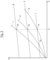
- the control device 12 is designed such that it controls or regulates the drive motor 10 according to at least one control scheme, ie, for example, according to a pump characteristic curve as shown in Fig. 3 It is known to use proportional pressure curves as a control scheme, for example, according to which the pressure increases in proportion to the flow. Alternatively, control schemes with constant pressure curves can also be used, in which the drive motor is controlled in such a way that the pressure remains at a constant value regardless of the flow.
- Fig. 3 shows three proportional pressure curves I, II and III in a QH diagram in which the pressure H is plotted against the flow Q. In the diagram according to Fig.
- system characteristic curves A, B and C represent the pressure loss in the hydraulic circuit depending on the flow rate Q.
- an operating point is set at the intersection of the pump characteristic curve and the system characteristic curve. If, for example, the circulation pump unit is operated with pump characteristic curve I and the hydraulic system in which the circulation pump unit is used has system characteristic curve A, the operating point 14 is set at the intersection of both characteristic curves.
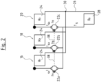
- Fig. 2 shows a schematic diagram of a heating system with three heating circuits or heating branches 16, 18 and 20.
- a circulation pump unit 22a, 22b or 22c is arranged and one or more consumers 24, such as radiators or loops of an underfloor heating system, are located.
- the three heating circuits 16, 18, 20 also lead through a common Flow path 26, which runs through a heat source 28, such as a boiler.
- a heat source 28 such as a boiler.
- the three heating circuits 16, 18, 20 branch off from one another on the output side of the heat source 28 and run through the circulation pump units 22a, 22b and 22c through the respective consumers 24 of the three heating circuits 16, 18, 20.
- the three heating circuits flow back into the common flow path 26 at the outlet point 30.
- the three heating circuits 16, 18, 20 can, for example, heat different parts of a building; alternatively, heating circuit 16 could, for example, be a heating circuit for underfloor heating, while heating circuits 18 and 20 represent heating circuits with normal radiators.
- the flow direction s could also run in the opposite direction.
- the hydraulic load or the hydraulic resistance formed by the consumers 24 is downstream of the circulation pump units 22. If the flow direction is opposite, the consumers 24 would be upstream of the circulation pump units 22. This could be the case, for example, if the multiple heating circuits 16, 18, 20 heat different apartments and the circulation pump units 22 are each part of an apartment station.
- the system characteristic curve A shown represents, for example, a system characteristic curve when only one of the circulation pumps 22, for example the circulation pump 22a, is in operation. If the heating circuit 18 is now also put into operation and, for example, the circulation pump 22b is also put into operation taken, the total flow rate through the common flow path 26 increases and with it the pressure loss across the heat source 28, so that the system then has the system characteristic curve B.
- the circulating pump unit 22a If the circulating pump unit 22a is now operated with the pump characteristic curve I, the operating point on this pump characteristic curve I would move from the operating point 14 to the operating point 32, which represents the intersection point between the pump characteristic curve I and the system characteristic curve B. This means that the circulating pump unit 22 would reduce its speed, the flow and the pressure would decrease. This would mean that the heating circuit 16 and the consumer 24 would no longer be adequately supplied, i.e. the flow through the consumer 24 could not be kept constant.
- the control device 12 of the circulation pump unit is designed in such a way that it can change its control scheme depending on the operation of further circulation pump units 22 in parallel branches 18, 20 of the hydraulic system.
- the control device 12 can shift the pump characteristic curve I, which is used as the control scheme, so that the circulation pump unit is operated according to the second pump characteristic curve II, the intersection of which with the system characteristic curve B forms a new operating point 34, which is at the same flow rate q 1 as the operating point 14.
- the flow rate q 1 through the consumer 24 of the heating circuit 16 can be kept constant.
- the pressure H is increased so that the higher pressure loss in the common flow path 26 is compensated and the differential pressure across the consumer 24 can ideally be kept constant.
- the circulation pump unit 22a increases its speed and thus also its electrical power consumption. If the second circulation pump unit 22b is switched off again, the control scheme is changed back to the original pump characteristic curve I and the circulation pump unit 22a is again operated with the pump characteristic curve I at operating point 14.
- the control scheme of the circulation pump unit 22a can be changed so that it operates according to the pump characteristic curve III in Fig. 3 is operated so that operation takes place at operating point 36, which represents the intersection between the system characteristic curve C and the pump characteristic curve III.
- the flow rate q 1 is kept constant, but the pressure H increases so that the increased pressure loss in the common flow path 26 is compensated and the heating circuit 16 continues to be supplied with essentially a constant flow rate.
- the control schemes of the circulating pump units 22b and 22c in the heating circuits 18 and 20 are adapted accordingly depending on how many of the other heating circuits 16, 18, 20 are in operation. It should be understood that the circulating pump units 22a, 22b and 22c do not necessarily have to be put into operation in this order. Depending on the heat requirement in the individual heating circuits 16, 18, 20, for example, only the circulation pump unit 22c can be in operation and then the circulation pump units 22a and 22b can be put into operation. Any combination and sequence is conceivable here.
- the required compensations can be calculated from the hydraulic quantities in the manner described below.
- the consumers 24 in the heating circuits 16, 18, 20 have the hydraulic resistances R 1 , R 2 and R 3 .
- the flows s 1 , s 2 and s 3 caused by the respective circulation pump units 22a, 22b and 22c prevail.
- the circulation pump unit 22a generates a differential pressure h 1
- the circulation pump unit 22b a differential pressure h 2
- the circulation pump unit 22c has a differential pressure h 3 .
- the heat source 28 forms a hydraulic resistance R 0 .
- the hydraulic resistances R 0 , R 1 , R 2 and R 3 do not only represent the hydraulic resistance of the consumers or the heat source, but the entire hydraulic resistance in the respective branch, which is formed by line losses and the like.
- the hydraulic resistances R 1 , R 2 and R 3 vary, for example, depending on the degree of opening of a thermostat valve in the respective heating circuit 16, 18, 20.
- each branch has a differential pressure setpoint h*, which is to be achieved across the hydraulic resistance R.
- the circulation pump units 22 are not to be controlled at a constant pressure but at a proportional pressure depending on the flow in order to generate a proportional pressure curve.
- a and b represent parameters of the proportional pressure curve.
- the control devices 12 of the circulation pump units 22 are first caused to put all circulation pump units 22a, 22b and 22c into operation, preferably by appropriate communication via the communication interfaces 40 and data connections 38 described below.
- the control devices 12 determine the differential pressures h 1 , h 2 , h 3 and the flow rates s 1 , s 2 and s 3 and exchange them with one another, preferably via the data connections 38. These values can be recorded by suitable sensors in the circulation pump units 22 and/or by calculation based on electrical variables of the drive motor of the respective circulation pump unit 22.
- the circulation pump unit 22b can, for example, be switched off and pressure values h 1 , h' 2 , h 3 and flow rates s' 1 , s' 2 and s' 3 can be determined. From these measurements, the hydraulic resistance R 0 in the common flow path 26 can be determined by solving the following systems of equations with two unknowns.
- the change in the flow rate s in the common flow path 26 can later be taken into account for adjusting the pump characteristic curve in each individual circulation pump unit 22 when the flow rate changes due to switching on or changing the speed of one of the circulation pump units 22.
- the pump characteristic curve I, II, III is preferably shifted by a dimension or by a correction value which is proportional to the hydraulic resistance R 0 in the common flow path 26 and an increasing function of the sum of the flows, ie the flow rate s in the common flow path 26.
- the circulation pump units 22a, 22b and 22c can be connected to one another directly via data connections 38.
- the data connections 38 can be implemented as a wired data bus or wirelessly via radio connections.
- the control devices 12 of the circulation pump units 22 have a communication interface 40 for this purpose. This interacts with a detection module 42 inside the control device 12, which provides a detection function.
- the detection module 42 can be implemented as a software module in the control device.
- the control devices 12 also each have a signal generating device 44, which according to a first embodiment can also be connected to the communication interface 40, as in Fig. 1 is shown.
- the communication interface 40 preferably acts bidirectionally.
- the signal generating device 44 can also be implemented as a software module in the control device 12.
- the signal generating device 44 When the respective circulation pump unit 22 is operating, the signal generating device 44 generates a signal which represents a state variable and is output to the other circulation pump units 22 via the communication interface 40 and the data connection 38.
- the state variable can simply signal that the respective circulation pump unit 22 is or will be switched on or off.
- the state variable can be a flow rate value which represents the respective flow rate of the pump unit 22. The flow rate can either be measured in the circulation pump unit 22 or derived from electrical variables by the control device 12.
- the signal generation device 44 of the circulation pump unit 22b generates, for example, a flow rate value which indicates the flow rate of the second circulation pump unit 22b.
- This flow rate value is determined via the communication interface 40 and the data connection 38 to the first circulation pump unit 22a.
- Its control device 12 processes this signal in the detection module 42 in such a way that it now recognizes the change in the system characteristic curve from the system characteristic curve A to the system characteristic curve B and accordingly adjusts the control scheme of its control device 12, e.g. from the pump characteristic curve I to the pump characteristic curve II.
- the circulation pump unit 22c When the third circulation pump unit 22c is switched on, this takes place in a corresponding manner, in that the circulation pump unit 22c also transmits its flow rate value via the data connection 38 to the circulation pump unit 22b and the circulation pump unit 22a, so that these two circulation pump units can then change their pump characteristic curve again as a control scheme. Conversely, the circulation pump unit 22c also receives the flow rate values from the circulation pump units 22a and 22b, so that it can adapt its control scheme directly upon commissioning to the hydraulic state of the system resulting from the simultaneous operation of the other circulation pump units 22a and 22b.
- the control device 12 of the first pump unit 22a is only informed that the second circulation pump unit 22b is switched on or is operating, the control device 12 can automatically recognize via the detection module 42 from the change in the electrical variables and, if applicable, hydraulic variables measured directly in the circulation pump unit 22a how the system characteristic curve is changing and make a corresponding adjustment to the pump characteristic curve. This can be done in a corresponding manner in the other two circulation pump units 22b and 22c.
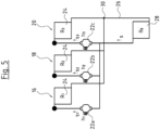
- the networking or linking for communication between the circulation pump units 22a, 22b and 22c can also be carried out in an alternative manner, for example in Fig. 4 is shown.
- the connection is made via a central control unit 46.
- the control unit 46 is each connected to the circulation pump units 22 via individual data connections 38'.
- the data connections 38' can in turn be wired or wireless, for example as radio connections.
- the central control unit 46 can be designed in such a way that it takes over the complete function of the control devices 12 in such a way that it specifies the respective speed for the drive motor 10 for the circulation pump units 22a, 22b, 22c, for example via a PWM signal input of the circulation pump units 22a, 22b and 22c.
- Such a central control and corresponding circulation pump units are not according to the invention.
- the control unit 46 only takes over the function of transmitting the state variables or signals between the circulation pump units 22, as described above, then the Fig. 4 illustrated embodiment and corresponding circulation pump units according to the invention. This can be particularly useful if the communication interfaces 40 of the control devices 12 are galvanically separated from the other parts of the control device, so that the communication connections 38' require an external power supply via the control unit 46.
- the communication between the circulation pump units 22a, 22b and 22c takes place hydraulically.
- the circulation pump units 22a, 22b, 22c do not require a communication interface 40.
- the signal generating device 44 generates a hydraulic signal when the respective circulation pump unit 22 is put into operation by putting the drive motor 10 into operation according to a predetermined pattern, for example, by briefly switching it on and off several times in a certain pattern before permanent operation.
- a circulation pump unit 22 in the system recognizes the pattern which signals the start-up of another circulation pump unit 22, it can recognize the change in the system characteristic curve A, B, C from its electrical variables or internal sensor signals in the manner described above and adapt the pump characteristic curve I, II, III accordingly, as described above. If necessary, such a hydraulic signal, which signals the operation of a pump unit, can also be generated at regular intervals by the signal generating device 44, so that the circulation pump units 22 can continuously monitor via their detection devices or detection modules 42 whether other circulation pump units 22 are in operation in the same hydraulic system.
Landscapes
- Engineering & Computer Science (AREA)
- Mechanical Engineering (AREA)
- General Engineering & Computer Science (AREA)
- Fluid-Pressure Circuits (AREA)
- Control Of Non-Positive-Displacement Pumps (AREA)
- Control Of Positive-Displacement Pumps (AREA)
Claims (15)
- Ensemble de pompe de circulation (22) avec un moteur d'entraînement électronique (10) et un système de commande électrique (12) pour commander le moteur d'entraînement (10), sachant que le système de commande (12) est constitué pour la régulation de régime du moteur d'entraînement (10) selon un schéma de régulation (I, II, III), sachant que le système de commande (12) comporte un système générateur de signaux (44), lequel est constitué pour générer un signal représentant la mise en marche et/ou l'arrêt ou une variation de régime du moteur d'entraînement (10), ainsi qu'une fonction de saisie (42) laquelle est constituée pour saisir une grandeur d'état représentant un état de fonctionnement d'au moins une branche hydraulique parallèle (16, 18, 20) avec un deuxième ensemble de pompe de circulation (22) du même type, en identifiant sous la forme d'une grandeur d'état un signal produit par le système générateur de signaux de l'autre ou de plusieurs ensembles de pompe de circulation , lequel représente la mise en marche et/ou l'arrêt ou une variation de régime d'au moins un deuxième ensemble de pompe de circulation (22), et
sachant que le système de commande (12) est constitué de telle manière qu'il peut adapter le schéma de régulation (I, II, III) propre sur la base d'une grandeur d'état saisie par la fonction de saisie (42) et le moteur d'entraînement (10) peut être commandé par le système de commande (12) en prenant en considération le signal saisi de telle sorte qu'une pression différentielle présente une valeur prédéfinie par le biais d'une résistance hydraulique appliquée dans une branche individuelle des branches hydrauliques. - Ensemble de pompe de circulation (22) selon la revendication 1, pour lequel la fonction de saisie (42) est constituée pour identifier un signal sous la forme d'au moins un modèle prédéterminé d'une charge hydraulique agissant sur l'ensemble de pompe de circulation (22).
- Ensemble de pompe de circulation (22) selon l'une quelconque des revendications précédentes, pour lequel le système de commande (12) comporte une interface de communication (40), laquelle est reliée à la fonction de saisie (42) de telle manière que la fonction de saisie (42) peut recevoir un signal par le biais de l'interface de communication (40).
- Ensemble de pompe de circulation (22) selon l'une quelconque des revendications précédentes, pour lequel le système générateur de signaux (44) est constitué pour produire un signal hydraulique.
- Ensemble de pompe de circulation (22) selon l'une quelconque des revendications précédentes, pour lequel le système de commande (12) comporte une interface de communication (40), laquelle est reliée au système générateur de signaux (44) de telle manière que le système générateur de signaux (44) peut émettre un signal ou une valeur par le biais de l'interface de communication (40).
- Ensemble de pompe de circulation (22) selon la revendication 5, pour lequel le système générateur de signaux (44) est constitué de telle manière qu'il émet par le biais de l'interface de communication (40) une valeur de débit représentant le débit actuel de l'ensemble de pompe de circulation (22).
- Ensemble de pompe de circulation (22) selon la revendication 6, pour lequel l'interface de communication (40) est constituée pour la liaison de communication d'une interface de communication (40) d'au moins un deuxième ensemble de pompe de circulation (22) de même type, le système de commande (12) est constitué de telle manière qu'il peut recevoir une grandeur d'état par le biais de l'interface de communication (40) et de la fonction de saisie (42) d'au moins un deuxième ensemble de pompe de circulation (22) de même type par le biais de l'interface de communication (40) et en ce que le système de commande (12) commande le moteur d'entraînement (10) en tenant compte de la grandeur d'état reçue par l'interface de communication (40).
- Ensemble de pompe de circulation (22) selon l'une quelconque des revendications précédentes, pour lequel le système de commande (12) est constitué de telle manière que le schéma de régulation (I, II, III), selon lequel le moteur d'entraînement (10) est réglé, comporte une caractéristique de pompage (I, II, III), laquelle est modifiée et de préférence déplacée sous la forme d'une grandeur d'état reçue en fonction d'un signal identifié ou reçu par la fonction de saisie (42).
- Ensemble de pompe de circulation selon la revendication 8, pour lequel le système de commande est constitué de telle manière que la caractéristique de pompage (I, II, III) est déplacée d'une valeur de correction, laquelle représente une fonction d'une grandeur d'état reçue ou saisie.
- Ensemble de pompe de circulation (22) selon l'une quelconque des revendications précédentes, pour lequel le système de commande (12) est constitué de telle manière qu'après réception d'un signal de la fonction de saisie (44), il modifie le schéma de régulation (I, II, III) automatiquement en fonction de la variation de la charge hydraulique et déplace en particulier une caractéristique de pompage (I, II, III) formant le schéma de régulation.
- Ensemble de pompe de circulation (22) selon l'une quelconque des revendications 6-10, pour lequel l'interface de communication (40) est constituée pour la communication avec plusieurs deuxièmes ensembles de pompe de circulation (22) de même type et le système de commande (12) commande le moteur d'entraînement (10) en tenant compte de toutes les grandeurs d'état reçues par l'interface de communication (40).
- Ensemble de pompe de circulation (22) selon l'une quelconque des revendications précédentes, pour lequel le système de commande (12) est constitué de telle manière qu'il modifie le schéma de régulation pour une grandeur d'état prédéterminée saisie par la fonction de saisie (42) de telle sorte que le moteur d'entraînement (10) est mis à l'arrêt.
- Agencement d'au moins deux ensembles de pompe de circulation (22) de même type selon l'une quelconque des revendications précédentes, pour lequel au moins les deux ensembles de pompe de circulation (22) dans un système circulatoire sont disposés dans deux branches parallèles l'une à l'autre (16, 18, 20) et les systèmes de commande (12) des ensembles de pompe de circulation (22) comportent respectivement un système générateur de signaux (44), lequel émet une grandeur d'état, laquelle représente un état de fonctionnement de cet ensemble de pompe de circulation (22) et les systèmes de commande (12) des ensembles de pompe de circulation (22) sont constitués de telle manière qu'ils commandent le moteur d'entraînement (10) respectif de l'ensemble de pompe de circulation (22) en tenant compte de la grandeur d'état saisie par sa fonction de saisie (44) et émise par l'autre ensembles de pompe de circulation (22) de telle manière qu'une pression différentielle comporte une valeur prédéfinie par le biais d'une résistance hydraulique appliquée dans une branche individuelle des branches hydrauliques.
- Procédé de commande d'au moins deux ensembles de pompe de circulation de même type disposés dans un système de circulation hydraulique dans des branches parallèles l'une à l'autre (16, 18, 20), de préférence deux branches de consommateurs parallèles l'une à l'autre (16, 18, 20), selon l'une quelconque des revendications 1-12, pour lequel lors de la mise en marche d'un deuxième ensemble de pompe de circulation (22), un schéma de régulation (I, II, III) selon lequel un premier ensemble de pompe de circulation (22) est commandé, est modifié en tenant compte de la puissance hydraulique fournie par le deuxième ensemble de pompe de circulation (22) et pour lequel au moins les deux branches parallèles (16, 18, 20) du système hydraulique débouchent dans une voie d'écoulement commune (26) et en ce qu'au moins le premier ensemble de pompe de circulation (22) et de préférence tous les ensemble de pompe de circulation (22) disposés dans les branches parallèles (16, 18, 20) sont commandés de telle manière que leur schéma de régulation (I, II, III) est adapté respectivement sur la base d'une perte hydraulique dans la voie d'écoulement commune de telle sorte qu'une pression différentielle comporte une valeur prédéfinie dans une résistance (24) hydraulique appliquée à une branche individuelle des branches hydrauliques (16, 18, 20).
- Procédé selon la revendication 14 pour lequel une grandeur de la puissance hydraulique fournie par le deuxième ensemble de pompe de circulation (22) est transmise par le deuxième ensemble de pompe de circulation (22) au premier ensemble de pompe de circulation (22) ou est déterminée par le premier ensemble de pompe de circulation (22) automatiquement à l'aide d'une variation de charge intervenant dans le premier ensemble de pompe de circulation (22).
Priority Applications (4)
| Application Number | Priority Date | Filing Date | Title |
|---|---|---|---|
| EP17159191.0A EP3369934B1 (fr) | 2017-03-03 | 2017-03-03 | Pompe de circulation |
| CN201880015575.7A CN110392787B (zh) | 2017-03-03 | 2018-02-26 | 循环泵机组 |
| US16/490,129 US11371509B2 (en) | 2017-03-03 | 2018-02-26 | Parallel circulation pump coordinating control assembly |
| PCT/EP2018/054693 WO2018158197A1 (fr) | 2017-03-03 | 2018-02-26 | Unité de pompe de circulation |
Applications Claiming Priority (1)
| Application Number | Priority Date | Filing Date | Title |
|---|---|---|---|
| EP17159191.0A EP3369934B1 (fr) | 2017-03-03 | 2017-03-03 | Pompe de circulation |
Publications (3)
| Publication Number | Publication Date |
|---|---|
| EP3369934A1 EP3369934A1 (fr) | 2018-09-05 |
| EP3369934B1 true EP3369934B1 (fr) | 2024-12-11 |
| EP3369934C0 EP3369934C0 (fr) | 2024-12-11 |
Family
ID=58228022
Family Applications (1)
| Application Number | Title | Priority Date | Filing Date |
|---|---|---|---|
| EP17159191.0A Active EP3369934B1 (fr) | 2017-03-03 | 2017-03-03 | Pompe de circulation |
Country Status (4)
| Country | Link |
|---|---|
| US (1) | US11371509B2 (fr) |
| EP (1) | EP3369934B1 (fr) |
| CN (1) | CN110392787B (fr) |
| WO (1) | WO2018158197A1 (fr) |
Families Citing this family (2)
| Publication number | Priority date | Publication date | Assignee | Title |
|---|---|---|---|---|
| DE102023107205A1 (de) * | 2023-03-22 | 2024-09-26 | KSB SE & Co. KGaA | Verfahren zur Regelung eines Pumpensystems, das zumindest zwei hydraulisch parallel betriebene Kreiselpumpen aufweist, sowie Mehrpumpensystem |
| DE102023113580A1 (de) * | 2023-05-24 | 2024-11-28 | KSB SE & Co. KGaA | Verfahren zum Betrieb einer Mehrpumpenanlage mit wenigstens zwei hydraulisch parallel betreibbaren Pumpen sowie Mehrpumpenanlage |
Citations (2)
| Publication number | Priority date | Publication date | Assignee | Title |
|---|---|---|---|---|
| US20020033420A1 (en) * | 2000-08-02 | 2002-03-21 | Somchai Paarporn | Decentralized pumping system |
| US20100300540A1 (en) * | 2006-09-01 | 2010-12-02 | Edgar Grosse Westhoff | Method for operating a network of pipes |
Family Cites Families (14)
| Publication number | Priority date | Publication date | Assignee | Title |
|---|---|---|---|---|
| US3511579A (en) * | 1968-07-22 | 1970-05-12 | Liquitrol Systems Inc | Control system for liquid pressure booster systems |
| JPH0737791B2 (ja) * | 1988-11-28 | 1995-04-26 | 株式会社日立製作所 | ポンプの逆流検出装置及び揚水設備のポンプ運転制御装置並びに可変速揚水発電電動装置 |
| DE19511170A1 (de) * | 1995-03-28 | 1996-10-02 | Wilo Gmbh | Doppelpumpe mit übergeordneter Steuerung |
| AU3053799A (en) * | 1998-04-03 | 1999-10-25 | Ebara Corporation | Diagnosing system for fluid machinery |
| US7010393B2 (en) * | 2002-06-20 | 2006-03-07 | Compressor Controls Corporation | Controlling multiple pumps operating in parallel or series |
| EP2229610B1 (fr) * | 2007-12-14 | 2019-03-06 | ITT Manufacturing Enterprises LLC | Equilibre de couple synchrone dans des systèmes de pompes multiples |
| FI127255B (en) * | 2011-11-02 | 2018-02-15 | Abb Technology Oy | Method and controller for operating the pump system |
| PL2708825T3 (pl) * | 2012-09-12 | 2017-08-31 | Grundfos Holding A/S | Sposób sterowania pompą obiegową w instalacji z co najmniej dwoma obwodami cyrkulacyjnymi |
| EP2895746B1 (fr) * | 2012-09-13 | 2019-01-02 | ABB Schweiz AG | Dispositif et procédé permettant de faire fonctionner des pompes centrifuges parallèles |
| SG11201503927RA (en) | 2012-12-12 | 2015-06-29 | Armstrong Ltd S A | Self learning control system and method for optimizing a consumable input variable |
| JP6184792B2 (ja) * | 2013-07-26 | 2017-08-23 | 株式会社荏原製作所 | 給水装置 |
| DK2871420T3 (en) * | 2013-11-07 | 2016-12-19 | Grundfos Holding As | Cirkulationspumpeaggregat to a heating and / or cooling system |
| NO20150759A1 (en) * | 2015-06-11 | 2016-10-24 | Fmc Kongsberg Subsea As | Load-sharing in parallel fluid pumps |
| FR3058479B1 (fr) * | 2016-11-08 | 2018-11-02 | Schneider Toshiba Inverter Europe Sas | Procede et systeme de commande d'un equipement multi-pompes |
-
2017
- 2017-03-03 EP EP17159191.0A patent/EP3369934B1/fr active Active
-
2018
- 2018-02-26 CN CN201880015575.7A patent/CN110392787B/zh active Active
- 2018-02-26 US US16/490,129 patent/US11371509B2/en active Active
- 2018-02-26 WO PCT/EP2018/054693 patent/WO2018158197A1/fr not_active Ceased
Patent Citations (2)
| Publication number | Priority date | Publication date | Assignee | Title |
|---|---|---|---|---|
| US20020033420A1 (en) * | 2000-08-02 | 2002-03-21 | Somchai Paarporn | Decentralized pumping system |
| US20100300540A1 (en) * | 2006-09-01 | 2010-12-02 | Edgar Grosse Westhoff | Method for operating a network of pipes |
Also Published As
| Publication number | Publication date |
|---|---|
| WO2018158197A1 (fr) | 2018-09-07 |
| EP3369934C0 (fr) | 2024-12-11 |
| CN110392787A (zh) | 2019-10-29 |
| EP3369934A1 (fr) | 2018-09-05 |
| US20200011330A1 (en) | 2020-01-09 |
| CN110392787B (zh) | 2022-03-25 |
| US11371509B2 (en) | 2022-06-28 |
Similar Documents
| Publication | Publication Date | Title |
|---|---|---|
| EP2960587B1 (fr) | Procédé de limitation du débit d'alimentation dans un système de transmission de chaleur | |
| EP1286240B1 (fr) | Méthode de détermination d'une caractéristique de pompe | |
| EP2871423B1 (fr) | Procédé de régulation pour un système de chauffage et/ou de refroidissement comprenant au moins un circuit de charge et dispositif de distribution pour un système de chauffage et/ou de refroidissement | |
| EP2469094B1 (fr) | Procédé de fonctionnement d'un agrégat de pompes doubles ou multipompes | |
| DE102008064490B4 (de) | Verfahren zum Steuern einer Kompressoranlage mittels rechnerischer Minimierung des Abschaltdrucks sowie Steuerungseinrichtung und Datensatz | |
| EP2085707A2 (fr) | Installation de chauffage et procédé destiné au fonctionnement d'une installation de chauffage | |
| EP1936288B1 (fr) | Procédé et système destinés à la détection d'un équilibrage hydraulique d'une installation de chauffage | |
| EP2708825B1 (fr) | Procédé de commande d'une pompe de recirculation dans une installation avec au moins deux circuits | |
| EP2863134B1 (fr) | Procédé d'adaptation d'une courbe de chauffe | |
| EP2806168B1 (fr) | Module de pompe de circulation et installation thermosolaire le comprenant | |
| EP2985536B1 (fr) | Procédé de réglage pour un groupe motopompe | |
| DE102015014378A1 (de) | Verfahren zur Regelung einer Kreiselpumpe sowie zugehöriges Pumpensystem | |
| EP2871539B1 (fr) | Procédé de diagnostic pour le diagnostic du fonctionnement correct d'un système de chauffage et/ou de refroidissement | |
| EP2187136A2 (fr) | Procédé de fonctionnement d'un système de transport d'énergie thermique sur un support fluide | |
| EP3101352B1 (fr) | Procede de fonctionnement d'une installation de chauffage et dispositif de regulation comprenant un capteur de difference de pression | |
| EP3369934B1 (fr) | Pompe de circulation | |
| EP3026352A1 (fr) | Procede de regulation hydraulique de plusieurs circuits de chauffe sur nourrices de distribution | |
| EP2871424B1 (fr) | Procédé de régulation pour un système de chauffage et/ou de refroidissement et dispositif de distribution pour un système de chauffage et/ou de refroidissement | |
| DE4312150C2 (de) | Verfahren zum Einstellen der Förderleistung einer Umwälzpumpe | |
| EP1191287A2 (fr) | Système de tuyauterie pour l'échange d'énergie thermique | |
| DE102010017148A1 (de) | Verfahren zum Betreiben einer Wärmegewinnungsanlage | |
| EP2795198A1 (fr) | Dispositif de commande d'une pompe de circulation de chauffage et procédé de commande associé | |
| EP3997389B1 (fr) | Procédé de commande d'un ensemble composé d'une pompe de chauffage et d'une vanne mélangeuse à trois voies | |
| DE102010047913A1 (de) | Intelligenter Heizkreisverteiler und Verfahren zum Betrieb desselben | |
| DE102005040792B3 (de) | Selbstlernender Temperaturregler |
Legal Events
| Date | Code | Title | Description |
|---|---|---|---|
| PUAI | Public reference made under article 153(3) epc to a published international application that has entered the european phase |
Free format text: ORIGINAL CODE: 0009012 |
|
| STAA | Information on the status of an ep patent application or granted ep patent |
Free format text: STATUS: THE APPLICATION HAS BEEN PUBLISHED |
|
| AK | Designated contracting states |
Kind code of ref document: A1 Designated state(s): AL AT BE BG CH CY CZ DE DK EE ES FI FR GB GR HR HU IE IS IT LI LT LU LV MC MK MT NL NO PL PT RO RS SE SI SK SM TR |
|
| AX | Request for extension of the european patent |
Extension state: BA ME |
|
| STAA | Information on the status of an ep patent application or granted ep patent |
Free format text: STATUS: REQUEST FOR EXAMINATION WAS MADE |
|
| 17P | Request for examination filed |
Effective date: 20190305 |
|
| RBV | Designated contracting states (corrected) |
Designated state(s): AL AT BE BG CH CY CZ DE DK EE ES FI FR GB GR HR HU IE IS IT LI LT LU LV MC MK MT NL NO PL PT RO RS SE SI SK SM TR |
|
| STAA | Information on the status of an ep patent application or granted ep patent |
Free format text: STATUS: EXAMINATION IS IN PROGRESS |
|
| 17Q | First examination report despatched |
Effective date: 20210312 |
|
| GRAP | Despatch of communication of intention to grant a patent |
Free format text: ORIGINAL CODE: EPIDOSNIGR1 |
|
| STAA | Information on the status of an ep patent application or granted ep patent |
Free format text: STATUS: GRANT OF PATENT IS INTENDED |
|
| RIC1 | Information provided on ipc code assigned before grant |
Ipc: F04D 15/02 20060101ALN20240201BHEP Ipc: F04D 13/06 20060101ALI20240201BHEP Ipc: F04D 15/00 20060101ALI20240201BHEP Ipc: F04D 13/12 20060101AFI20240201BHEP |
|
| INTG | Intention to grant announced |
Effective date: 20240214 |
|
| GRAJ | Information related to disapproval of communication of intention to grant by the applicant or resumption of examination proceedings by the epo deleted |
Free format text: ORIGINAL CODE: EPIDOSDIGR1 |
|
| STAA | Information on the status of an ep patent application or granted ep patent |
Free format text: STATUS: EXAMINATION IS IN PROGRESS |
|
| GRAP | Despatch of communication of intention to grant a patent |
Free format text: ORIGINAL CODE: EPIDOSNIGR1 |
|
| INTC | Intention to grant announced (deleted) | ||
| STAA | Information on the status of an ep patent application or granted ep patent |
Free format text: STATUS: GRANT OF PATENT IS INTENDED |
|
| RIC1 | Information provided on ipc code assigned before grant |
Ipc: F04D 15/02 20060101ALN20240618BHEP Ipc: F04D 13/06 20060101ALI20240618BHEP Ipc: F04D 15/00 20060101ALI20240618BHEP Ipc: F04D 13/12 20060101AFI20240618BHEP |
|
| INTG | Intention to grant announced |
Effective date: 20240718 |
|
| GRAS | Grant fee paid |
Free format text: ORIGINAL CODE: EPIDOSNIGR3 |
|
| GRAA | (expected) grant |
Free format text: ORIGINAL CODE: 0009210 |
|
| STAA | Information on the status of an ep patent application or granted ep patent |
Free format text: STATUS: THE PATENT HAS BEEN GRANTED |
|
| AK | Designated contracting states |
Kind code of ref document: B1 Designated state(s): AL AT BE BG CH CY CZ DE DK EE ES FI FR GB GR HR HU IE IS IT LI LT LU LV MC MK MT NL NO PL PT RO RS SE SI SK SM TR |
|
| REG | Reference to a national code |
Ref country code: GB Ref legal event code: FG4D Free format text: NOT ENGLISH |
|
| REG | Reference to a national code |
Ref country code: CH Ref legal event code: EP |
|
| REG | Reference to a national code |
Ref country code: DE Ref legal event code: R096 Ref document number: 502017016602 Country of ref document: DE |
|
| REG | Reference to a national code |
Ref country code: IE Ref legal event code: FG4D Free format text: LANGUAGE OF EP DOCUMENT: GERMAN |
|
| U01 | Request for unitary effect filed |
Effective date: 20250110 |
|
| U07 | Unitary effect registered |
Designated state(s): AT BE BG DE DK EE FI FR IT LT LU LV MT NL PT RO SE SI Effective date: 20250117 |
|
| U1O | Appointed representative for the unitary patent procedure deleted after the registration of the unitary effect | ||
| PG25 | Lapsed in a contracting state [announced via postgrant information from national office to epo] |
Ref country code: HR Free format text: LAPSE BECAUSE OF FAILURE TO SUBMIT A TRANSLATION OF THE DESCRIPTION OR TO PAY THE FEE WITHIN THE PRESCRIBED TIME-LIMIT Effective date: 20241211 |
|
| PG25 | Lapsed in a contracting state [announced via postgrant information from national office to epo] |
Ref country code: ES Free format text: LAPSE BECAUSE OF FAILURE TO SUBMIT A TRANSLATION OF THE DESCRIPTION OR TO PAY THE FEE WITHIN THE PRESCRIBED TIME-LIMIT Effective date: 20241211 |
|
| PG25 | Lapsed in a contracting state [announced via postgrant information from national office to epo] |
Ref country code: NO Free format text: LAPSE BECAUSE OF FAILURE TO SUBMIT A TRANSLATION OF THE DESCRIPTION OR TO PAY THE FEE WITHIN THE PRESCRIBED TIME-LIMIT Effective date: 20250311 |
|
| PG25 | Lapsed in a contracting state [announced via postgrant information from national office to epo] |
Ref country code: GR Free format text: LAPSE BECAUSE OF FAILURE TO SUBMIT A TRANSLATION OF THE DESCRIPTION OR TO PAY THE FEE WITHIN THE PRESCRIBED TIME-LIMIT Effective date: 20250312 |
|
| PG25 | Lapsed in a contracting state [announced via postgrant information from national office to epo] |
Ref country code: RS Free format text: LAPSE BECAUSE OF FAILURE TO SUBMIT A TRANSLATION OF THE DESCRIPTION OR TO PAY THE FEE WITHIN THE PRESCRIBED TIME-LIMIT Effective date: 20250311 |
|
| U20 | Renewal fee for the european patent with unitary effect paid |
Year of fee payment: 9 Effective date: 20250325 |
|
| PG25 | Lapsed in a contracting state [announced via postgrant information from national office to epo] |
Ref country code: SM Free format text: LAPSE BECAUSE OF FAILURE TO SUBMIT A TRANSLATION OF THE DESCRIPTION OR TO PAY THE FEE WITHIN THE PRESCRIBED TIME-LIMIT Effective date: 20241211 |
|
| PG25 | Lapsed in a contracting state [announced via postgrant information from national office to epo] |
Ref country code: PL Free format text: LAPSE BECAUSE OF FAILURE TO SUBMIT A TRANSLATION OF THE DESCRIPTION OR TO PAY THE FEE WITHIN THE PRESCRIBED TIME-LIMIT Effective date: 20241211 |
|
| PG25 | Lapsed in a contracting state [announced via postgrant information from national office to epo] |
Ref country code: IS Free format text: LAPSE BECAUSE OF FAILURE TO SUBMIT A TRANSLATION OF THE DESCRIPTION OR TO PAY THE FEE WITHIN THE PRESCRIBED TIME-LIMIT Effective date: 20250411 |
|
| PG25 | Lapsed in a contracting state [announced via postgrant information from national office to epo] |
Ref country code: SK Free format text: LAPSE BECAUSE OF FAILURE TO SUBMIT A TRANSLATION OF THE DESCRIPTION OR TO PAY THE FEE WITHIN THE PRESCRIBED TIME-LIMIT Effective date: 20241211 |
|
| PG25 | Lapsed in a contracting state [announced via postgrant information from national office to epo] |
Ref country code: CZ Free format text: LAPSE BECAUSE OF FAILURE TO SUBMIT A TRANSLATION OF THE DESCRIPTION OR TO PAY THE FEE WITHIN THE PRESCRIBED TIME-LIMIT Effective date: 20241211 |
|
| PG25 | Lapsed in a contracting state [announced via postgrant information from national office to epo] |
Ref country code: MC Free format text: LAPSE BECAUSE OF FAILURE TO SUBMIT A TRANSLATION OF THE DESCRIPTION OR TO PAY THE FEE WITHIN THE PRESCRIBED TIME-LIMIT Effective date: 20241211 |
|
| PLBE | No opposition filed within time limit |
Free format text: ORIGINAL CODE: 0009261 |
|
| STAA | Information on the status of an ep patent application or granted ep patent |
Free format text: STATUS: NO OPPOSITION FILED WITHIN TIME LIMIT |
|
| REG | Reference to a national code |
Ref country code: CH Ref legal event code: L10 Free format text: ST27 STATUS EVENT CODE: U-0-0-L10-L00 (AS PROVIDED BY THE NATIONAL OFFICE) Effective date: 20251022 |
|
| REG | Reference to a national code |
Ref country code: CH Ref legal event code: H13 Free format text: ST27 STATUS EVENT CODE: U-0-0-H10-H13 (AS PROVIDED BY THE NATIONAL OFFICE) Effective date: 20251023 |
|
| 26N | No opposition filed |
Effective date: 20250912 |
|
| PG25 | Lapsed in a contracting state [announced via postgrant information from national office to epo] |
Ref country code: CH Free format text: LAPSE BECAUSE OF NON-PAYMENT OF DUE FEES Effective date: 20250331 |
|
| PG25 | Lapsed in a contracting state [announced via postgrant information from national office to epo] |
Ref country code: IE Free format text: LAPSE BECAUSE OF NON-PAYMENT OF DUE FEES Effective date: 20250303 |
|
| PGFP | Annual fee paid to national office [announced via postgrant information from national office to epo] |
Ref country code: GB Payment date: 20260324 Year of fee payment: 10 |
|
| U20 | Renewal fee for the european patent with unitary effect paid |
Year of fee payment: 10 Effective date: 20260326 |