EP3370882B1 - Système cyclonique - Google Patents
Système cyclonique Download PDFInfo
- Publication number
- EP3370882B1 EP3370882B1 EP16810230.9A EP16810230A EP3370882B1 EP 3370882 B1 EP3370882 B1 EP 3370882B1 EP 16810230 A EP16810230 A EP 16810230A EP 3370882 B1 EP3370882 B1 EP 3370882B1
- Authority
- EP
- European Patent Office
- Prior art keywords
- cyclone
- cone
- wall
- flow
- cyclone system
- Prior art date
- Legal status (The legal status is an assumption and is not a legal conclusion. Google has not performed a legal analysis and makes no representation as to the accuracy of the status listed.)
- Active
Links
Images



Classifications
-
- B—PERFORMING OPERATIONS; TRANSPORTING
- B04—CENTRIFUGAL APPARATUS OR MACHINES FOR CARRYING-OUT PHYSICAL OR CHEMICAL PROCESSES
- B04C—APPARATUS USING FREE VORTEX FLOW, e.g. CYCLONES
- B04C5/00—Apparatus in which the axial direction of the vortex is reversed
- B04C5/08—Vortex chamber constructions
- B04C5/081—Shapes or dimensions
-
- B—PERFORMING OPERATIONS; TRANSPORTING
- B04—CENTRIFUGAL APPARATUS OR MACHINES FOR CARRYING-OUT PHYSICAL OR CHEMICAL PROCESSES
- B04C—APPARATUS USING FREE VORTEX FLOW, e.g. CYCLONES
- B04C5/00—Apparatus in which the axial direction of the vortex is reversed
- B04C5/02—Construction of inlets by which the vortex flow is generated, e.g. tangential admission, the fluid flow being forced to follow a downward path by spirally wound bulkheads, or with slightly downwardly-directed tangential admission
- B04C5/04—Tangential inlets
-
- B—PERFORMING OPERATIONS; TRANSPORTING
- B04—CENTRIFUGAL APPARATUS OR MACHINES FOR CARRYING-OUT PHYSICAL OR CHEMICAL PROCESSES
- B04C—APPARATUS USING FREE VORTEX FLOW, e.g. CYCLONES
- B04C5/00—Apparatus in which the axial direction of the vortex is reversed
- B04C5/14—Construction of the underflow ducting; Apex constructions; Discharge arrangements ; discharge through sidewall provided with a few slits or perforations
-
- B—PERFORMING OPERATIONS; TRANSPORTING
- B04—CENTRIFUGAL APPARATUS OR MACHINES FOR CARRYING-OUT PHYSICAL OR CHEMICAL PROCESSES
- B04C—APPARATUS USING FREE VORTEX FLOW, e.g. CYCLONES
- B04C5/00—Apparatus in which the axial direction of the vortex is reversed
- B04C5/14—Construction of the underflow ducting; Apex constructions; Discharge arrangements ; discharge through sidewall provided with a few slits or perforations
- B04C5/15—Construction of the underflow ducting; Apex constructions; Discharge arrangements ; discharge through sidewall provided with a few slits or perforations with swinging flaps or revolving sluices; Sluices; Check-valves
-
- B—PERFORMING OPERATIONS; TRANSPORTING
- B04—CENTRIFUGAL APPARATUS OR MACHINES FOR CARRYING-OUT PHYSICAL OR CHEMICAL PROCESSES
- B04C—APPARATUS USING FREE VORTEX FLOW, e.g. CYCLONES
- B04C5/00—Apparatus in which the axial direction of the vortex is reversed
- B04C5/14—Construction of the underflow ducting; Apex constructions; Discharge arrangements ; discharge through sidewall provided with a few slits or perforations
- B04C5/18—Construction of the underflow ducting; Apex constructions; Discharge arrangements ; discharge through sidewall provided with a few slits or perforations with auxiliary fluid assisting discharge
-
- B—PERFORMING OPERATIONS; TRANSPORTING
- B04—CENTRIFUGAL APPARATUS OR MACHINES FOR CARRYING-OUT PHYSICAL OR CHEMICAL PROCESSES
- B04C—APPARATUS USING FREE VORTEX FLOW, e.g. CYCLONES
- B04C5/00—Apparatus in which the axial direction of the vortex is reversed
- B04C5/14—Construction of the underflow ducting; Apex constructions; Discharge arrangements ; discharge through sidewall provided with a few slits or perforations
- B04C5/185—Dust collectors
-
- B—PERFORMING OPERATIONS; TRANSPORTING
- B04—CENTRIFUGAL APPARATUS OR MACHINES FOR CARRYING-OUT PHYSICAL OR CHEMICAL PROCESSES
- B04C—APPARATUS USING FREE VORTEX FLOW, e.g. CYCLONES
- B04C5/00—Apparatus in which the axial direction of the vortex is reversed
- B04C5/24—Multiple arrangement thereof
- B04C5/26—Multiple arrangement thereof for series flow
-
- D—TEXTILES; PAPER
- D21—PAPER-MAKING; PRODUCTION OF CELLULOSE
- D21B—FIBROUS RAW MATERIALS OR THEIR MECHANICAL TREATMENT
- D21B1/00—Fibrous raw materials or their mechanical treatment
- D21B1/04—Fibrous raw materials or their mechanical treatment by dividing raw materials into small particles, e.g. fibres
- D21B1/12—Fibrous raw materials or their mechanical treatment by dividing raw materials into small particles, e.g. fibres by wet methods, by the use of steam
- D21B1/30—Defibrating by other means
- D21B1/34—Kneading or mixing; Pulpers
-
- D—TEXTILES; PAPER
- D21—PAPER-MAKING; PRODUCTION OF CELLULOSE
- D21D—TREATMENT OF THE MATERIALS BEFORE PASSING TO THE PAPER-MAKING MACHINE
- D21D5/00—Purification of the pulp suspension by mechanical means; Apparatus therefor
- D21D5/18—Purification of the pulp suspension by mechanical means; Apparatus therefor with the aid of centrifugal force
- D21D5/24—Purification of the pulp suspension by mechanical means; Apparatus therefor with the aid of centrifugal force in cyclones
-
- B—PERFORMING OPERATIONS; TRANSPORTING
- B04—CENTRIFUGAL APPARATUS OR MACHINES FOR CARRYING-OUT PHYSICAL OR CHEMICAL PROCESSES
- B04C—APPARATUS USING FREE VORTEX FLOW, e.g. CYCLONES
- B04C9/00—Combinations with other devices, e.g. fans, expansion chambers, diffusors, water locks
- B04C2009/008—Combinations with other devices, e.g. fans, expansion chambers, diffusors, water locks with injection or suction of gas or liquid into the cyclone
Definitions
- the invention relates to a cyclone system.
- the invention relates to a rotary separator.
- Such systems are from the WO 2016/023536 A2 known.
- the invention relates to a cyclone as described there.
- a hydrocyclone with a particularly long lower cone is from the U.S. 3,612,276 A known.
- the use of a porous material in the cone describes the DE 10 92 886 B .
- the conditioner Before treating the particles in the cyclone, it is advantageous to treat them in a conditioner. Particles mixed with liquid, which are frayed in the conditioner, are particularly relevant here.
- the conditioner is then used for intensive blending and the friction of the particles against one another causes fiberization.
- the effectiveness of the conditioner and, in particular, the energy consumption required for the defibering depend heavily on the design of the conditioner.
- the particles washed out in the lower reaches of a conditioner can be further treated in a preferably single-stage or multi-stage hydrocyclone in order to separate out in particular sand-like particles.
- a hydrocyclone is simple in construction, leads to good efficiency and requires little energy.
- aluminum particles can also be discharged in such a hydrocyclone. Fibers that accumulate in the cyclone can either be separated in a disc filter or thickener or returned to the processor in the area of the upper reaches.
- a multi-stage wash can follow, which begins with a highly enriched wash water and ends with quasi fresh water.
- the DE 10 92 886 B describes a cyclone, the lower end of which is made of a porous material and is surrounded by a cylinder filled with water. This brings about an even supply of water on the inside of the porous material.
- the porous material causes an undirected, strongly damped water supply, which extends evenly over the entire conical area of the porous material.
- the invention is based on the object of improving the selectivity of a cyclone system. This is achieved by a cyclone system with the features of patent claim 1 and a method with the features of patent claim 8.
- the fractions be separated from the mixture in a liquid that is lighter or heavier than water. This can be achieved, for example, by adding salt or alcohol to the water.
- hydrophobic liquids such as oils can also be used.
- materials with a density greater than 1 g / cm 3 are deposited in the hydrocyclone.
- this can be influenced by special flow conditions.
- a liquid such as in particular water can be fed in at the lower end of the hydrocyclone in a tapering collecting cone or a discharge cone in order to achieve a countercurrent.
- the liquid is preferably supplied via nozzles or inflow openings. These can be distributed on the circumference in one or more levels.
- the inflow should be dimensioned in such a way that a laminar flow favors the separation.
- a cyclone system is created from several cyclones connected in series.
- the cyclones are preferably designed as cyclones in which a widening exit cone is connected to the central outlet.
- a batch fraction is treated first in a first cyclone and then in a second cyclone, with more liquid being supplied in countercurrent in the first cyclone to increase the selectivity than in the second cyclone.
- a high degree of selectivity can be achieved by means of a large amount of liquid fed in countercurrent, while the amount of liquid fed in can be reduced in the subsequent cyclone or in the subsequent cyclones.
- a regulation enables material, preferably as a pasty material, to be continuously removed from at least the first cyclone on the discharge cone.
- a discharge valve is only opened so far that a sediment of discharge material remains in the cyclone and the discharge is carried out continuously according to the input.
- sensors can determine the height of the sediment in the discharge in order to control the opening of the valve via a control device.
- the Figure 1 shows the integration of a conditioner 1 in a device with a large hydrocyclone 2.
- This hydrocyclone 2 has an inlet cone 3 and a head area 4. In the head area, a tangential inlet 5 and a central outlet 6 are provided.
- the inlet cone 3 can extend up to the head area 4, so that the head area is also conical. In an alternative embodiment, the inlet cone 3 can also be cylindrical.
- the conditioner 1 has a screw 13 in its upper area 12 and a sieve 14 underneath, which separates the upper area 12 from an underflow 15.
- the screw 13 is preferably designed as a spiral which only touches the screen plate directly above the screen 14 and drives the material radially outward.
- a screw leading to the spiral is preferably dispensed with in order to avoid the entry of air into the lower area of the conditioner and to facilitate the discharge of air in the conditioner.
- the substance mixture 16 treated in the conditioner 1 is discharged with a discharge screw 17 and conveyed to a buffer 18, which can hold a larger amount of the substance mixture in order to feed it to a collector 19 as required, from where the material is conveyed to the decentralized inlet 5 of the hydrocyclone 2 via a centrifugal pump 20.
- the collector 21 serves to dilute the circulated material with water 22 and then add it to the centrifugal pump 20 in liquid form.
- the collector 21 can therefore be designed as a screw conveyor to which liquid is added in order to achieve a consistency that can be conveyed via the centrifugal pump 20.
- discharge helix or discharge screw 17 and buffer 19 instead of discharge helix or discharge screw 17 and buffer 19, a particularly large discharge helix can be provided, which on the one hand makes it possible to withdraw material from the overflow of conditioner 1 and on the other hand to store as much material as possible, which is then gradually liquefied and the centrifugal pump 20 is added.
- the material first migrates in a spiral shape up to the constriction 7 and from there further into the exit cone 8, where a material fraction is removed via the lock 10. The remaining material migrates in a spiral shape in the exit cone 8 back up into the entrance cone 3 and via the central outlet 6 back to the conditioner 1.
- Feed openings 23 in the lower region 8 of the cyclone 2 allow water or another liquid to be fed in, in order to facilitate the separation of the material in the cyclone by means of a radial flow component directed from the outside to the inside.
- the feed openings can be designed as nozzles which allow a liquid to enter the cyclone in a defined flow direction.
- the main flow passes in an arc into the line 25 and from there to the circulation pump 26.
- This circulation pump 26 thus conveys from the central outlet 6 of the cyclone 2 to the tangential inlet 5 of the cyclone 2.
- the circuit between the hydrocyclone 2, the conditioner 1 and the centrifugal pump 20 makes it possible to treat the mixture 16 over a longer period of time and to remove different fractions from the circuit at the discharge opening 11.
- the sliding gate 18 is moved and the light material, such as in particular polyolefins such as polyethylene and polypropylene, is discharged.
- the light material such as in particular polyolefins such as polyethylene and polypropylene
- plastic materials can be separated in the hydrocyclone 2 simply by choosing the liquid 22.
- the plastics can be separated in a further cyclone which contains a liquid that is lighter or heavier than water.
- New material 28 is added as a mixture of substances either upstream of the centrifugal pump 20 to the collector 21 or at another point, for example at the buffer 19.
- the underflow 15 of the conditioner 1 is fed via a pump 29 to a small cyclone 30, where sand or, for example, aluminum 31 is separated and discharged, while a suspension 32 cleaned of coarse grain is fed to a second small cyclone 33, in which fine grain 34 sinks and is discharged, while cleaned pulp 35 is discharged via the overflow and fed to a filter 36.
- a small cyclone 30 where sand or, for example, aluminum 31 is separated and discharged, while a suspension 32 cleaned of coarse grain is fed to a second small cyclone 33, in which fine grain 34 sinks and is discharged, while cleaned pulp 35 is discharged via the overflow and fed to a filter 36.
- the fibrous materials are separated off, while the liquid reaches the collector 21 via the line 37 and from there to the centrifugal pump 20.
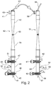
- the Figure 8 shows the use of two large cyclones connected in series.
- a small cyclone has a maximum diameter of less than 0.5 m and an inlet diameter of less than 100 mm, while a large cyclone has a maximum diameter of more than 0.7 m and a diameter at the inlet of more than 150 mm.
- the arrangement corresponds to that in Figure 1 described and it is different first a cyclone 2 and then a cyclone 2 'run through.
- cyclones are preferably connected in series.
- the material 40 to be treated enters the first cyclone 42 via the tangential inlet 41. In this, the flow separates the material into a suspension 43 and coarse grain 44, which has been cleaned of coarse grain and which can be removed from the first cyclone 42 through the discharge 45.
- a collecting container 46 at the lower end of the cyclone 42, which is delimited at the top and bottom by a slide 47 and 48, respectively.
- the openings 49 and 50 in the collecting container 46 are used for supplying and removing filling water and for venting.
- An opening 51 above the slide 47 and in the lower area of the cyclone 42 is used to supply countercurrent water to the cyclone 42 in the lower area.
- the cyclone 42 consists of an upper part 52 which is conical or cylindrical and a constriction 53 under which a conical cyclone element widens downwards.
- the second cyclone 55 is connected downstream of the first cyclone 42 and the suspension 43, which has been cleaned of coarse grain, on the upper reaches of the first cyclone 42 is fed to the tangential inlet 56 of the second cyclone 55.
- This second cyclone 55 is constructed like the first cyclone 42 and it is used to separate the fine grain 57 from the suspension 57 which has been cleaned of coarse grain and which is removed from the second cyclone 55 at the discharge 58. Coarse grain and fine grain are removed from the upper reaches of the second cyclone 55 Suspension 59 taken from the second cyclone 55.
- countercurrent water 60 supports the separation in the cyclone and sliders 61 and 62 delimit a collecting container 63 on which openings 64 and 65 are provided for ventilation and for filling water.
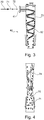
- the Figure 3 shows how coarse grain 70, fine grain 71 and fibrous material 72 are fed in at the tangential inlet 41.
- This pulp suspension 70, 71, 72 contaminated with coarse grain and fine grain is conveyed tangentially into the first cyclone 42 by means of a pump 29.
- a downwardly directed vortex 73 which is referred to as the primary vortex, is formed in the cyclone 42.
- This primary vortex initially pulls pulp, coarse grain and fine grain down.
- the particles with a higher specific gravity than that of the liquid are coarse grain 70 and fine grain 71 in the present case. These particles are pressed outwardly from the primary vortex 73 by the high centrifugal force and sink down at the edge of the cone 52.
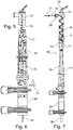
- the Figure 5 shows that the sinking of the lighter fine grain 71 is prevented from sinking by countercurrent water 51, which is supplied from below, and is initially held in suspension in cone 54.
- the lighter fine grain 71 then gets into the upward vortex 74 and is transported together with the fibrous material 72 via the upper reaches into the second cyclone 55.
- the heavier coarse grain 70 is not stopped by the countercurrent water 51 and continues to sink. This creates a pure coarse grain fraction 44 in the first cyclone 42, which can be drawn off in pasty form via the collecting container 46.
- the result of the fractionation can thus be determined by the amount of countercurrent water 51.
- the Figure 7 shows the separation in the second cyclone 55, at the tangential inlet 56 of which the pulp suspension made of pulp 72 and fine grain 71 is fed from the coarse grain.
- the pulp 72 and fine grain 71 form a primary vortex 76 in the upper part 75 of the second cyclone 55, and fine grain 71 is pushed outward out of the primary vortex 76 and sinks downwards at the edge of the cone 75.
- the cleaned fibrous material 72 is discharged with the secondary vortex 77 via the upper course 78.
- the fine grain 71 sinks in the second cyclone 55, so that a fine grain fraction arises in the lower region 79 of the second cyclone 55, which can be drawn off as a pasty fine grain fraction 80 via the collecting container 63.
- no countercurrent water is generally used in the second cyclone 55.
- the upper part of the cyclone can have a cylindrical area or even be completely cylindrical up to the constriction.
- this cylindrical area as a tube in the upper area of the cyclone could be shorter than the conical area below the constriction.
- the Figure 9 shows a hydrocyclone 90 which can be used as a small and in particular also as a large cyclone.
- the liquid to be treated enters the cyclone tangentially and migrates in a spiral shape on the conical wall 92, which can also be cylindrical, up to a point 93, after which an exit cone 94 adjoins.
- the small angle 95 of the wall 92 of 6 to 7 ° with respect to the central axis 96 ensures a sufficiently laminar flow in the outlet cone.
- the outer wall 98 has two inlets 100, 101 for water or gas and the inner wall 102 has an upper region 108 above the inlets 100 and 101 with a large number of feed openings 104. Since the feed openings are bores in the inner wall 103 which are perpendicular are bored into the wall, a feed flow 105 arises at a lift angle 106 of more than 0 ° and preferably less than 20 ° relative to a normal 107 of the central axis 96.
- the bores of the feed openings 104 have a diameter of 2 to 6 mm and preferably of about 4 mm.
- the inlets 100 and 101 lead to a flow which impacts against the opposite outer side of the inner wall 103 and is distributed between the inner wall 103 and the outer wall 98. This creates an overpressure between the walls, which ensures that a uniform and evenly distributed flow reaches the cyclone through the large number of feed openings 104, which flows slightly upwards to give the particles in the cyclone an upward impulse. This increases the effect that the light particles flow upwards while the heavier particles sink downwards.
Landscapes
- Engineering & Computer Science (AREA)
- Mechanical Engineering (AREA)
- Physics & Mathematics (AREA)
- Geometry (AREA)
- Life Sciences & Earth Sciences (AREA)
- Wood Science & Technology (AREA)
- Fluid Mechanics (AREA)
- Cyclones (AREA)
Claims (10)
- Système cyclonique, destiné notamment à un conditionneur (1), pourvu d'une zone haute (4), qui comporte une arrivée (5) décentrée, de préférence tangentielle, et une évacuation (6) centrale, et un cône de sortie (8) qui s'évase, doté d'un axe (96) central, caractérisé en ce qu 'une paroi (103) est à double paroi par endroits et comporte sur la paroi (98) extérieure au moins un orifice d'arrivée (100, 101) et comporte sur la paroi (103) intérieure une pluralité d'orifices d'alimentation (104), sur le cône de sortie (8) se raccordant un cône collecteur (9) se rétrécissant de nouveau, qui comporte l'orifice d'arrivée (100, 101) qui est placé dans une zone (108) dans laquelle la paroi (103) intérieure ne comporte aucun orifice d'alimentation (104), de telle sorte que la paroi (103) forme un déflecteur pour le milieu alimenté à travers l'orifice d'arrivée (100, 101).
- Système cyclonique selon la revendication 1, caractérisé en ce que la zone haute (4) est de forme cylindrique jusqu'au cône de sortie (8) qui s'évase.
- Système cyclonique selon l'une quelconque des revendications précédentes, caractérisé en ce que sur le cône de sortie (8) ou sur le cône collecteur (9) se raccorde un orifice de décharge (11) fermable.
- Système cyclonique selon la revendication 3, caractérisé en ce que l'orifice de décharge (11) comporte un sas (10).
- Système cyclonique selon la revendication 3 ou 4, caractérisé en ce que l'orifice de décharge (11) comporte une soupape qui permet une décharge réglée en continu.
- Système cyclonique selon l'une quelconque des revendications précédentes, caractérisé en ce que pour une arrivée d'un liquide ou d'un gaz, les orifices d'alimentation (104) sont placés dans la paroi (103) de sorte à donner naissance à un courant d'alimentation (105) sous un angle de flottabilité (106) de plus de 0° et de préférence, de moins de 20° en rapport à une normale (107) de l'axe (96) central.
- Système cyclonique selon l'une quelconque des revendications précédentes, caractérisé en ce que plusieurs cyclones (2, 2') de ce type, d'un diamètre maximum de plus de 0,7 m et pourvus d'une arrivée (5) tangentielle d'un diamètre de plus de 150 mm sont montés les uns derrière les autres, pour augmenter le taux d'épuration.
- Procédé, destiné à faire fonctionner successivement des cyclones (2, 2') pourvus de cônes de sortie (8, 8') qui s'évasent, dans les cônes de sortie (8, 8') qui s'évasent, le courant étant réglé de telle sorte qu'en service, le cône de sortie (8, 8') soit totalement rempli de liquide et que dans la zone extérieure, on soit en présence d'un courant dirigé en rotation vers le bas et dans la zone centrale, on soit en présence d'un courant dirigé vers le haut, caractérisé en ce que pour augmenter la sélectivité, une plus grande quantité de liquide est alimentée dans le premier cyclone que dans le deuxième cyclone.
- Procédé selon la revendication 8, caractérisé en ce qu'en service, également la zone haute (4) respective des cyclones est totalement remplie de liquide et dans la zone extérieure, on est en présence d'un courant dirigé en rotation vers le bas et dans la zone centrale, on est en présence d'un courant dirigé vers le haut.
- Procédé selon la revendication 8 ou 9, caractérisé en ce qu 'on prélève en continu de la matière, de préférence sous la forme d'une matière pâteuse sur l'orifice de décharge (11) au moins dans le premier cyclone.
Applications Claiming Priority (3)
| Application Number | Priority Date | Filing Date | Title |
|---|---|---|---|
| DE102015014285 | 2015-11-06 | ||
| DE102016007548.1A DE102016007548A1 (de) | 2015-11-06 | 2016-06-22 | Zyklonsystem |
| PCT/DE2016/000388 WO2017076384A1 (fr) | 2015-11-06 | 2016-11-07 | Système cyclonique |
Publications (2)
| Publication Number | Publication Date |
|---|---|
| EP3370882A1 EP3370882A1 (fr) | 2018-09-12 |
| EP3370882B1 true EP3370882B1 (fr) | 2021-01-06 |
Family
ID=58584427
Family Applications (1)
| Application Number | Title | Priority Date | Filing Date |
|---|---|---|---|
| EP16810230.9A Active EP3370882B1 (fr) | 2015-11-06 | 2016-11-07 | Système cyclonique |
Country Status (10)
| Country | Link |
|---|---|
| US (1) | US20190060918A1 (fr) |
| EP (1) | EP3370882B1 (fr) |
| JP (1) | JP2018533479A (fr) |
| KR (1) | KR20180090281A (fr) |
| AU (1) | AU2016351053A1 (fr) |
| CA (1) | CA3004375A1 (fr) |
| DE (2) | DE102016007548A1 (fr) |
| HK (1) | HK1253278A1 (fr) |
| RU (1) | RU2018120722A (fr) |
| WO (1) | WO2017076384A1 (fr) |
Cited By (1)
| Publication number | Priority date | Publication date | Assignee | Title |
|---|---|---|---|---|
| DE102022110164A1 (de) | 2021-08-26 | 2023-03-02 | Voith Patent Gmbh | Hydrozyklonanordnung |
Families Citing this family (2)
| Publication number | Priority date | Publication date | Assignee | Title |
|---|---|---|---|---|
| US11932816B2 (en) * | 2019-02-15 | 2024-03-19 | Exxonmobil Chemical Patents Inc. | Coke and tar removal from a furnace effluent |
| CA3153460A1 (fr) * | 2021-03-30 | 2022-09-30 | Kyata Capital Inc. | Systemes et methodes d'elimination de contaminants des surfaces de materiaux solides |
Citations (1)
| Publication number | Priority date | Publication date | Assignee | Title |
|---|---|---|---|---|
| GB2284165A (en) * | 1993-11-24 | 1995-05-31 | Winton Eurotech Limited | Dust Separator |
Family Cites Families (9)
| Publication number | Priority date | Publication date | Assignee | Title |
|---|---|---|---|---|
| US2735547A (en) * | 1956-02-21 | vissac | ||
| BE501733A (fr) * | 1950-03-09 | |||
| DE1092886B (de) * | 1953-09-16 | 1960-11-17 | Bauer Bros Company | Hydrozyklon zum Abtrennen von Faserstoffen aus einer Suspension |
| AT285486B (de) * | 1968-04-22 | 1970-10-27 | Oesterr Amerikan Magnesit | Verfahren und Zentrifugalkraftklassierer zum Trennen einer Trübe in mehrere Kornanteile |
| US3612276A (en) * | 1969-04-29 | 1971-10-12 | Bird Machine Co | Vortex-type separator apparatus |
| DE2410700A1 (de) * | 1974-03-06 | 1975-09-11 | Bayer Ag | Verfahren zur abscheidung von feststoffen aus einem gasstrom und dafuer geeignete vorrichtung |
| US4960525A (en) * | 1988-09-26 | 1990-10-02 | The United States Of America, As Represented By The Secretary Of Agriculture | Hydrocyclone for washing particles in liquid suspension |
| DE202005003104U1 (de) * | 2005-02-25 | 2005-05-12 | Voith Paper Patent Gmbh | Schwerteilaustragsvorrichtung für einen zum Abscheiden von Schwerteilen aus einer Faserstoffsuspension bestimmten Hydrozyklon |
| AT512479B1 (de) * | 2012-02-10 | 2013-11-15 | Andritz Energy & Environment Gmbh | Verfahren zur feinstoffreduktion im rea-gips |
-
2016
- 2016-06-22 DE DE102016007548.1A patent/DE102016007548A1/de not_active Withdrawn
- 2016-11-07 CA CA3004375A patent/CA3004375A1/fr not_active Abandoned
- 2016-11-07 RU RU2018120722A patent/RU2018120722A/ru not_active Application Discontinuation
- 2016-11-07 HK HK18112567.8A patent/HK1253278A1/zh unknown
- 2016-11-07 WO PCT/DE2016/000388 patent/WO2017076384A1/fr not_active Ceased
- 2016-11-07 JP JP2018543425A patent/JP2018533479A/ja active Pending
- 2016-11-07 KR KR1020187015992A patent/KR20180090281A/ko not_active Withdrawn
- 2016-11-07 US US15/773,622 patent/US20190060918A1/en not_active Abandoned
- 2016-11-07 AU AU2016351053A patent/AU2016351053A1/en not_active Abandoned
- 2016-11-07 DE DE112016005089.5T patent/DE112016005089A5/de not_active Withdrawn
- 2016-11-07 EP EP16810230.9A patent/EP3370882B1/fr active Active
Patent Citations (1)
| Publication number | Priority date | Publication date | Assignee | Title |
|---|---|---|---|---|
| GB2284165A (en) * | 1993-11-24 | 1995-05-31 | Winton Eurotech Limited | Dust Separator |
Cited By (1)
| Publication number | Priority date | Publication date | Assignee | Title |
|---|---|---|---|---|
| DE102022110164A1 (de) | 2021-08-26 | 2023-03-02 | Voith Patent Gmbh | Hydrozyklonanordnung |
Also Published As
| Publication number | Publication date |
|---|---|
| DE102016007548A1 (de) | 2017-05-11 |
| DE112016005089A5 (de) | 2018-07-26 |
| US20190060918A1 (en) | 2019-02-28 |
| EP3370882A1 (fr) | 2018-09-12 |
| AU2016351053A1 (en) | 2018-05-24 |
| HK1253278A1 (zh) | 2019-06-14 |
| RU2018120722A3 (fr) | 2020-05-18 |
| RU2018120722A (ru) | 2019-12-06 |
| WO2017076384A1 (fr) | 2017-05-11 |
| JP2018533479A (ja) | 2018-11-15 |
| KR20180090281A (ko) | 2018-08-10 |
| CA3004375A1 (fr) | 2017-05-11 |
Similar Documents
| Publication | Publication Date | Title |
|---|---|---|
| AT511837B1 (de) | Hydrozyklon mit feinstoffabreicherung im zyklonunterlauf | |
| DE754339C (de) | Verfahren und Vorrichtung zum Entfernen von schweren Teilchen unter Fliehkraftwirkung aus einer Aufschwemmung, insbesondere von Zellstoff, Papierstoff u. dgl. | |
| DE870531C (de) | Verfahren und Vorrichtung zum Trennen von in einer Fluessigkeit suspendierten Feststoffen oder Gasen | |
| DE1069116B (de) | Verfahren und Vorrichtung zum Abscheiden von feste Stoffe enthaltenden Faserstoffaufschwemmungen an einem Hydrozyklon | |
| DE1461196A1 (de) | Verfahren und Vorrichtung zum Abscheiden von Unreinigkeiten aus einem Papierbrei und aehnlichen faserhaltigen Aufschwemmungen | |
| EP3370882B1 (fr) | Système cyclonique | |
| DE4426159A1 (de) | Flotationseinrichtung | |
| DE3871905T2 (de) | Verfahren und vorrichtung zur abtrennung und gewinnung von partikeln. | |
| DE102009039238B3 (de) | Hydrozyklonanordnung | |
| EP0398864A2 (fr) | Procédé et dispositif de séparation de matières d'un milieu | |
| DE102004025149A1 (de) | Drucksortierter zum Sieben einer Faserstoffsuspension | |
| DE19706775B4 (de) | Hackschnitzelwaschanlage | |
| EP3180473B1 (fr) | Dispositif et procédé de traitement d'un mélange de matières | |
| DE10331683B3 (de) | Verfahren und Siebapparat zum Sortieren einer verschmutzten Papierfasersuspension | |
| DE69936605T2 (de) | Eine Abscheider-Zentrifuge | |
| DE69514836T2 (de) | Siebvorrichtung | |
| WO2020187652A1 (fr) | Ensemble filtre à la manière d'un séparateur centrifuge | |
| DE202006003421U1 (de) | Vorrichtung zum Austragen von Schwerteilen aus einem Apparat zur Behandlung einer Faserstoffsuspension, insbesondere aus einem zum Reinigen einer Faserstoffsuspension betreibbaren Hydrozyklon | |
| EP4042023B1 (fr) | Séparateur dental | |
| EP4041123B1 (fr) | Separateur dental | |
| DE102013100694B4 (de) | Verfahren und Vorrichtung zur Aufbereitung einer von Zusatzstoffen verunreinigten Basisflüssikeit | |
| DE10218377B4 (de) | Verfahren und Vorrichtung zur Schwerstoffabtrennung aus Aufschlämmungen | |
| CH385170A (de) | Verfahren zum Aufbereiten von Flüssigkeiten und Hydrozyklon zur Durchführung dieses Verfahrens | |
| WO2017174500A1 (fr) | Procédé et installation servant au traitement de cendres provenant d'un incinérateur de déchets | |
| DE102015114519A1 (de) | Tangential-Separator (TS) |
Legal Events
| Date | Code | Title | Description |
|---|---|---|---|
| STAA | Information on the status of an ep patent application or granted ep patent |
Free format text: STATUS: UNKNOWN |
|
| STAA | Information on the status of an ep patent application or granted ep patent |
Free format text: STATUS: THE INTERNATIONAL PUBLICATION HAS BEEN MADE |
|
| PUAI | Public reference made under article 153(3) epc to a published international application that has entered the european phase |
Free format text: ORIGINAL CODE: 0009012 |
|
| STAA | Information on the status of an ep patent application or granted ep patent |
Free format text: STATUS: REQUEST FOR EXAMINATION WAS MADE |
|
| 17P | Request for examination filed |
Effective date: 20180530 |
|
| AK | Designated contracting states |
Kind code of ref document: A1 Designated state(s): AL AT BE BG CH CY CZ DE DK EE ES FI FR GB GR HR HU IE IS IT LI LT LU LV MC MK MT NL NO PL PT RO RS SE SI SK SM TR |
|
| AX | Request for extension of the european patent |
Extension state: BA ME |
|
| DAV | Request for validation of the european patent (deleted) | ||
| DAX | Request for extension of the european patent (deleted) | ||
| REG | Reference to a national code |
Ref country code: HK Ref legal event code: DE Ref document number: 1253278 Country of ref document: HK |
|
| STAA | Information on the status of an ep patent application or granted ep patent |
Free format text: STATUS: EXAMINATION IS IN PROGRESS |
|
| 17Q | First examination report despatched |
Effective date: 20190719 |
|
| GRAP | Despatch of communication of intention to grant a patent |
Free format text: ORIGINAL CODE: EPIDOSNIGR1 |
|
| STAA | Information on the status of an ep patent application or granted ep patent |
Free format text: STATUS: GRANT OF PATENT IS INTENDED |
|
| INTG | Intention to grant announced |
Effective date: 20200827 |
|
| GRAS | Grant fee paid |
Free format text: ORIGINAL CODE: EPIDOSNIGR3 |
|
| GRAA | (expected) grant |
Free format text: ORIGINAL CODE: 0009210 |
|
| STAA | Information on the status of an ep patent application or granted ep patent |
Free format text: STATUS: THE PATENT HAS BEEN GRANTED |
|
| AK | Designated contracting states |
Kind code of ref document: B1 Designated state(s): AL AT BE BG CH CY CZ DE DK EE ES FI FR GB GR HR HU IE IS IT LI LT LU LV MC MK MT NL NO PL PT RO RS SE SI SK SM TR |
|
| REG | Reference to a national code |
Ref country code: GB Ref legal event code: FG4D Free format text: NOT ENGLISH |
|
| REG | Reference to a national code |
Ref country code: AT Ref legal event code: REF Ref document number: 1351791 Country of ref document: AT Kind code of ref document: T Effective date: 20210115 Ref country code: CH Ref legal event code: EP |
|
| REG | Reference to a national code |
Ref country code: DE Ref legal event code: R096 Ref document number: 502016012162 Country of ref document: DE |
|
| REG | Reference to a national code |
Ref country code: IE Ref legal event code: FG4D Free format text: LANGUAGE OF EP DOCUMENT: GERMAN |
|
| REG | Reference to a national code |
Ref country code: NL Ref legal event code: MP Effective date: 20210106 |
|
| REG | Reference to a national code |
Ref country code: LT Ref legal event code: MG9D |
|
| PG25 | Lapsed in a contracting state [announced via postgrant information from national office to epo] |
Ref country code: FI Free format text: LAPSE BECAUSE OF FAILURE TO SUBMIT A TRANSLATION OF THE DESCRIPTION OR TO PAY THE FEE WITHIN THE PRESCRIBED TIME-LIMIT Effective date: 20210106 Ref country code: GR Free format text: LAPSE BECAUSE OF FAILURE TO SUBMIT A TRANSLATION OF THE DESCRIPTION OR TO PAY THE FEE WITHIN THE PRESCRIBED TIME-LIMIT Effective date: 20210407 Ref country code: HR Free format text: LAPSE BECAUSE OF FAILURE TO SUBMIT A TRANSLATION OF THE DESCRIPTION OR TO PAY THE FEE WITHIN THE PRESCRIBED TIME-LIMIT Effective date: 20210106 Ref country code: NO Free format text: LAPSE BECAUSE OF FAILURE TO SUBMIT A TRANSLATION OF THE DESCRIPTION OR TO PAY THE FEE WITHIN THE PRESCRIBED TIME-LIMIT Effective date: 20210406 Ref country code: PT Free format text: LAPSE BECAUSE OF FAILURE TO SUBMIT A TRANSLATION OF THE DESCRIPTION OR TO PAY THE FEE WITHIN THE PRESCRIBED TIME-LIMIT Effective date: 20210506 Ref country code: LT Free format text: LAPSE BECAUSE OF FAILURE TO SUBMIT A TRANSLATION OF THE DESCRIPTION OR TO PAY THE FEE WITHIN THE PRESCRIBED TIME-LIMIT Effective date: 20210106 Ref country code: BG Free format text: LAPSE BECAUSE OF FAILURE TO SUBMIT A TRANSLATION OF THE DESCRIPTION OR TO PAY THE FEE WITHIN THE PRESCRIBED TIME-LIMIT Effective date: 20210406 |
|
| PG25 | Lapsed in a contracting state [announced via postgrant information from national office to epo] |
Ref country code: LV Free format text: LAPSE BECAUSE OF FAILURE TO SUBMIT A TRANSLATION OF THE DESCRIPTION OR TO PAY THE FEE WITHIN THE PRESCRIBED TIME-LIMIT Effective date: 20210106 Ref country code: RS Free format text: LAPSE BECAUSE OF FAILURE TO SUBMIT A TRANSLATION OF THE DESCRIPTION OR TO PAY THE FEE WITHIN THE PRESCRIBED TIME-LIMIT Effective date: 20210106 Ref country code: PL Free format text: LAPSE BECAUSE OF FAILURE TO SUBMIT A TRANSLATION OF THE DESCRIPTION OR TO PAY THE FEE WITHIN THE PRESCRIBED TIME-LIMIT Effective date: 20210106 Ref country code: SE Free format text: LAPSE BECAUSE OF FAILURE TO SUBMIT A TRANSLATION OF THE DESCRIPTION OR TO PAY THE FEE WITHIN THE PRESCRIBED TIME-LIMIT Effective date: 20210106 |
|
| PG25 | Lapsed in a contracting state [announced via postgrant information from national office to epo] |
Ref country code: IS Free format text: LAPSE BECAUSE OF FAILURE TO SUBMIT A TRANSLATION OF THE DESCRIPTION OR TO PAY THE FEE WITHIN THE PRESCRIBED TIME-LIMIT Effective date: 20210506 |
|
| REG | Reference to a national code |
Ref country code: DE Ref legal event code: R097 Ref document number: 502016012162 Country of ref document: DE |
|
| PG25 | Lapsed in a contracting state [announced via postgrant information from national office to epo] |
Ref country code: EE Free format text: LAPSE BECAUSE OF FAILURE TO SUBMIT A TRANSLATION OF THE DESCRIPTION OR TO PAY THE FEE WITHIN THE PRESCRIBED TIME-LIMIT Effective date: 20210106 Ref country code: CZ Free format text: LAPSE BECAUSE OF FAILURE TO SUBMIT A TRANSLATION OF THE DESCRIPTION OR TO PAY THE FEE WITHIN THE PRESCRIBED TIME-LIMIT Effective date: 20210106 Ref country code: SM Free format text: LAPSE BECAUSE OF FAILURE TO SUBMIT A TRANSLATION OF THE DESCRIPTION OR TO PAY THE FEE WITHIN THE PRESCRIBED TIME-LIMIT Effective date: 20210106 |
|
| PLBE | No opposition filed within time limit |
Free format text: ORIGINAL CODE: 0009261 |
|
| STAA | Information on the status of an ep patent application or granted ep patent |
Free format text: STATUS: NO OPPOSITION FILED WITHIN TIME LIMIT |
|
| PG25 | Lapsed in a contracting state [announced via postgrant information from national office to epo] |
Ref country code: RO Free format text: LAPSE BECAUSE OF FAILURE TO SUBMIT A TRANSLATION OF THE DESCRIPTION OR TO PAY THE FEE WITHIN THE PRESCRIBED TIME-LIMIT Effective date: 20210106 Ref country code: SK Free format text: LAPSE BECAUSE OF FAILURE TO SUBMIT A TRANSLATION OF THE DESCRIPTION OR TO PAY THE FEE WITHIN THE PRESCRIBED TIME-LIMIT Effective date: 20210106 Ref country code: DK Free format text: LAPSE BECAUSE OF FAILURE TO SUBMIT A TRANSLATION OF THE DESCRIPTION OR TO PAY THE FEE WITHIN THE PRESCRIBED TIME-LIMIT Effective date: 20210106 |
|
| 26N | No opposition filed |
Effective date: 20211007 |
|
| PG25 | Lapsed in a contracting state [announced via postgrant information from national office to epo] |
Ref country code: ES Free format text: LAPSE BECAUSE OF FAILURE TO SUBMIT A TRANSLATION OF THE DESCRIPTION OR TO PAY THE FEE WITHIN THE PRESCRIBED TIME-LIMIT Effective date: 20210106 Ref country code: AL Free format text: LAPSE BECAUSE OF FAILURE TO SUBMIT A TRANSLATION OF THE DESCRIPTION OR TO PAY THE FEE WITHIN THE PRESCRIBED TIME-LIMIT Effective date: 20210106 |
|
| PG25 | Lapsed in a contracting state [announced via postgrant information from national office to epo] |
Ref country code: SI Free format text: LAPSE BECAUSE OF FAILURE TO SUBMIT A TRANSLATION OF THE DESCRIPTION OR TO PAY THE FEE WITHIN THE PRESCRIBED TIME-LIMIT Effective date: 20210106 |
|
| PG25 | Lapsed in a contracting state [announced via postgrant information from national office to epo] |
Ref country code: IT Free format text: LAPSE BECAUSE OF FAILURE TO SUBMIT A TRANSLATION OF THE DESCRIPTION OR TO PAY THE FEE WITHIN THE PRESCRIBED TIME-LIMIT Effective date: 20210106 |
|
| PG25 | Lapsed in a contracting state [announced via postgrant information from national office to epo] |
Ref country code: IS Free format text: LAPSE BECAUSE OF FAILURE TO SUBMIT A TRANSLATION OF THE DESCRIPTION OR TO PAY THE FEE WITHIN THE PRESCRIBED TIME-LIMIT Effective date: 20210506 |
|
| PG25 | Lapsed in a contracting state [announced via postgrant information from national office to epo] |
Ref country code: MC Free format text: LAPSE BECAUSE OF FAILURE TO SUBMIT A TRANSLATION OF THE DESCRIPTION OR TO PAY THE FEE WITHIN THE PRESCRIBED TIME-LIMIT Effective date: 20210106 |
|
| REG | Reference to a national code |
Ref country code: CH Ref legal event code: PL |
|
| GBPC | Gb: european patent ceased through non-payment of renewal fee |
Effective date: 20211107 |
|
| PG25 | Lapsed in a contracting state [announced via postgrant information from national office to epo] |
Ref country code: LU Free format text: LAPSE BECAUSE OF NON-PAYMENT OF DUE FEES Effective date: 20211107 Ref country code: BE Free format text: LAPSE BECAUSE OF NON-PAYMENT OF DUE FEES Effective date: 20211130 |
|
| REG | Reference to a national code |
Ref country code: BE Ref legal event code: MM Effective date: 20211130 |
|
| PG25 | Lapsed in a contracting state [announced via postgrant information from national office to epo] |
Ref country code: IE Free format text: LAPSE BECAUSE OF NON-PAYMENT OF DUE FEES Effective date: 20211107 Ref country code: GB Free format text: LAPSE BECAUSE OF NON-PAYMENT OF DUE FEES Effective date: 20211107 |
|
| REG | Reference to a national code |
Ref country code: AT Ref legal event code: MM01 Ref document number: 1351791 Country of ref document: AT Kind code of ref document: T Effective date: 20211107 |
|
| PG25 | Lapsed in a contracting state [announced via postgrant information from national office to epo] |
Ref country code: AT Free format text: LAPSE BECAUSE OF NON-PAYMENT OF DUE FEES Effective date: 20211107 |
|
| PG25 | Lapsed in a contracting state [announced via postgrant information from national office to epo] |
Ref country code: HU Free format text: LAPSE BECAUSE OF FAILURE TO SUBMIT A TRANSLATION OF THE DESCRIPTION OR TO PAY THE FEE WITHIN THE PRESCRIBED TIME-LIMIT; INVALID AB INITIO Effective date: 20161107 |
|
| PG25 | Lapsed in a contracting state [announced via postgrant information from national office to epo] |
Ref country code: CY Free format text: LAPSE BECAUSE OF FAILURE TO SUBMIT A TRANSLATION OF THE DESCRIPTION OR TO PAY THE FEE WITHIN THE PRESCRIBED TIME-LIMIT Effective date: 20210106 Ref country code: NL Free format text: LAPSE BECAUSE OF NON-PAYMENT OF DUE FEES Effective date: 20210206 |
|
| PG25 | Lapsed in a contracting state [announced via postgrant information from national office to epo] |
Ref country code: LI Free format text: LAPSE BECAUSE OF NON-PAYMENT OF DUE FEES Effective date: 20220630 Ref country code: CH Free format text: LAPSE BECAUSE OF NON-PAYMENT OF DUE FEES Effective date: 20220630 |
|
| PG25 | Lapsed in a contracting state [announced via postgrant information from national office to epo] |
Ref country code: MK Free format text: LAPSE BECAUSE OF FAILURE TO SUBMIT A TRANSLATION OF THE DESCRIPTION OR TO PAY THE FEE WITHIN THE PRESCRIBED TIME-LIMIT Effective date: 20210106 |
|
| PG25 | Lapsed in a contracting state [announced via postgrant information from national office to epo] |
Ref country code: MT Free format text: LAPSE BECAUSE OF FAILURE TO SUBMIT A TRANSLATION OF THE DESCRIPTION OR TO PAY THE FEE WITHIN THE PRESCRIBED TIME-LIMIT Effective date: 20210106 |
|
| REG | Reference to a national code |
Ref country code: HK Ref legal event code: WD Ref document number: 1253278 Country of ref document: HK |
|
| PG25 | Lapsed in a contracting state [announced via postgrant information from national office to epo] |
Ref country code: TR Free format text: LAPSE BECAUSE OF FAILURE TO SUBMIT A TRANSLATION OF THE DESCRIPTION OR TO PAY THE FEE WITHIN THE PRESCRIBED TIME-LIMIT Effective date: 20210106 |
|
| PGFP | Annual fee paid to national office [announced via postgrant information from national office to epo] |
Ref country code: DE Payment date: 20251127 Year of fee payment: 10 |
|
| PGFP | Annual fee paid to national office [announced via postgrant information from national office to epo] |
Ref country code: FR Payment date: 20251126 Year of fee payment: 10 |