EP3371507B1 - Schutzring für gasflaschen - Google Patents
Schutzring für gasflaschen Download PDFInfo
- Publication number
- EP3371507B1 EP3371507B1 EP16798418.6A EP16798418A EP3371507B1 EP 3371507 B1 EP3371507 B1 EP 3371507B1 EP 16798418 A EP16798418 A EP 16798418A EP 3371507 B1 EP3371507 B1 EP 3371507B1
- Authority
- EP
- European Patent Office
- Prior art keywords
- ring
- protective ring
- wall
- protective
- stand
- Prior art date
- Legal status (The legal status is an assumption and is not a legal conclusion. Google has not performed a legal analysis and makes no representation as to the accuracy of the status listed.)
- Active
Links
Images


Classifications
-
- F—MECHANICAL ENGINEERING; LIGHTING; HEATING; WEAPONS; BLASTING
- F17—STORING OR DISTRIBUTING GASES OR LIQUIDS
- F17C—VESSELS FOR CONTAINING OR STORING COMPRESSED, LIQUEFIED OR SOLIDIFIED GASES; FIXED-CAPACITY GAS-HOLDERS; FILLING VESSELS WITH, OR DISCHARGING FROM VESSELS, COMPRESSED, LIQUEFIED, OR SOLIDIFIED GASES
- F17C13/00—Details of vessels or of the filling or discharging of vessels
- F17C13/08—Mounting arrangements for vessels
- F17C13/084—Mounting arrangements for vessels for small-sized storage vessels, e.g. compressed gas cylinders or bottles, disposable gas vessels, vessels adapted for automotive use
-
- F—MECHANICAL ENGINEERING; LIGHTING; HEATING; WEAPONS; BLASTING
- F17—STORING OR DISTRIBUTING GASES OR LIQUIDS
- F17C—VESSELS FOR CONTAINING OR STORING COMPRESSED, LIQUEFIED OR SOLIDIFIED GASES; FIXED-CAPACITY GAS-HOLDERS; FILLING VESSELS WITH, OR DISCHARGING FROM VESSELS, COMPRESSED, LIQUEFIED, OR SOLIDIFIED GASES
- F17C2201/00—Vessel construction, in particular geometry, arrangement or size
- F17C2201/05—Size
- F17C2201/058—Size portable (<30 l)
-
- F—MECHANICAL ENGINEERING; LIGHTING; HEATING; WEAPONS; BLASTING
- F17—STORING OR DISTRIBUTING GASES OR LIQUIDS
- F17C—VESSELS FOR CONTAINING OR STORING COMPRESSED, LIQUEFIED OR SOLIDIFIED GASES; FIXED-CAPACITY GAS-HOLDERS; FILLING VESSELS WITH, OR DISCHARGING FROM VESSELS, COMPRESSED, LIQUEFIED, OR SOLIDIFIED GASES
- F17C2203/00—Vessel construction, in particular walls or details thereof
- F17C2203/06—Materials for walls or layers thereof; Properties or structures of walls or their materials
- F17C2203/0634—Materials for walls or layers thereof
- F17C2203/0636—Metals
-
- F—MECHANICAL ENGINEERING; LIGHTING; HEATING; WEAPONS; BLASTING
- F17—STORING OR DISTRIBUTING GASES OR LIQUIDS
- F17C—VESSELS FOR CONTAINING OR STORING COMPRESSED, LIQUEFIED OR SOLIDIFIED GASES; FIXED-CAPACITY GAS-HOLDERS; FILLING VESSELS WITH, OR DISCHARGING FROM VESSELS, COMPRESSED, LIQUEFIED, OR SOLIDIFIED GASES
- F17C2205/00—Vessel construction, in particular mounting arrangements, attachments or identifications means
- F17C2205/01—Mounting arrangements
- F17C2205/0153—Details of mounting arrangements
- F17C2205/018—Supporting feet
-
- F—MECHANICAL ENGINEERING; LIGHTING; HEATING; WEAPONS; BLASTING
- F17—STORING OR DISTRIBUTING GASES OR LIQUIDS
- F17C—VESSELS FOR CONTAINING OR STORING COMPRESSED, LIQUEFIED OR SOLIDIFIED GASES; FIXED-CAPACITY GAS-HOLDERS; FILLING VESSELS WITH, OR DISCHARGING FROM VESSELS, COMPRESSED, LIQUEFIED, OR SOLIDIFIED GASES
- F17C2221/00—Handled fluid, in particular type of fluid
- F17C2221/03—Mixtures
- F17C2221/032—Hydrocarbons
- F17C2221/035—Propane butane, e.g. LPG, GPL
-
- F—MECHANICAL ENGINEERING; LIGHTING; HEATING; WEAPONS; BLASTING
- F17—STORING OR DISTRIBUTING GASES OR LIQUIDS
- F17C—VESSELS FOR CONTAINING OR STORING COMPRESSED, LIQUEFIED OR SOLIDIFIED GASES; FIXED-CAPACITY GAS-HOLDERS; FILLING VESSELS WITH, OR DISCHARGING FROM VESSELS, COMPRESSED, LIQUEFIED, OR SOLIDIFIED GASES
- F17C2223/00—Handled fluid before transfer, i.e. state of fluid when stored in the vessel or before transfer from the vessel
- F17C2223/01—Handled fluid before transfer, i.e. state of fluid when stored in the vessel or before transfer from the vessel characterised by the phase
- F17C2223/0146—Two-phase
- F17C2223/0153—Liquefied gas, e.g. LPG, GPL
-
- F—MECHANICAL ENGINEERING; LIGHTING; HEATING; WEAPONS; BLASTING
- F17—STORING OR DISTRIBUTING GASES OR LIQUIDS
- F17C—VESSELS FOR CONTAINING OR STORING COMPRESSED, LIQUEFIED OR SOLIDIFIED GASES; FIXED-CAPACITY GAS-HOLDERS; FILLING VESSELS WITH, OR DISCHARGING FROM VESSELS, COMPRESSED, LIQUEFIED, OR SOLIDIFIED GASES
- F17C2223/00—Handled fluid before transfer, i.e. state of fluid when stored in the vessel or before transfer from the vessel
- F17C2223/03—Handled fluid before transfer, i.e. state of fluid when stored in the vessel or before transfer from the vessel characterised by the pressure level
- F17C2223/033—Small pressure, e.g. for liquefied gas
-
- F—MECHANICAL ENGINEERING; LIGHTING; HEATING; WEAPONS; BLASTING
- F17—STORING OR DISTRIBUTING GASES OR LIQUIDS
- F17C—VESSELS FOR CONTAINING OR STORING COMPRESSED, LIQUEFIED OR SOLIDIFIED GASES; FIXED-CAPACITY GAS-HOLDERS; FILLING VESSELS WITH, OR DISCHARGING FROM VESSELS, COMPRESSED, LIQUEFIED, OR SOLIDIFIED GASES
- F17C2260/00—Purposes of gas storage and gas handling
- F17C2260/01—Improving mechanical properties or manufacturing
- F17C2260/015—Facilitating maintenance
-
- F—MECHANICAL ENGINEERING; LIGHTING; HEATING; WEAPONS; BLASTING
- F17—STORING OR DISTRIBUTING GASES OR LIQUIDS
- F17C—VESSELS FOR CONTAINING OR STORING COMPRESSED, LIQUEFIED OR SOLIDIFIED GASES; FIXED-CAPACITY GAS-HOLDERS; FILLING VESSELS WITH, OR DISCHARGING FROM VESSELS, COMPRESSED, LIQUEFIED, OR SOLIDIFIED GASES
- F17C2270/00—Applications
- F17C2270/07—Applications for household use
- F17C2270/0745—Gas bottles
Definitions
- the invention relates to a protective ring for the base ring of a gas cylinder, wherein the base ring has a circumferential wall which is connected to the gas cylinder via fastening elements, with a base surface whose inside is intended to receive the base ring of a gas cylinder, a wall circumferentially surrounding the base surface for contact with the wall of the base ring of a gas cylinder and a plurality of locking arms for fixing the protective ring to the base ring of a gas cylinder.
- Conventional gas cylinders consist of a cylinder with a valve at the top and a base ring at the bottom.
- the gas cylinder and base ring are usually made of metal, particularly steel suitable for the respective contents and pressure.
- the gas cylinder and base ring are usually welded together using fasteners, with openings or gaps remaining between individual fasteners.
- Stand rings typically have a wall surrounding the base, which is roughly aligned with the contour of the printing cylinder.
- the base is an inwardly deformed portion of the wall, which usually forms a ring with a width of about 1 cm.
- the friction between the base ring and the surface also causes damage to the base ring's paint, which primarily serves as corrosion protection. As a result, the base rings begin to rust, leaving traces of rust on the surface that are difficult to remove. Corrosion damage to the base rings requires extensive repair during gas cylinder inspections.
- a stand system for a gas cylinder according to US standards is known, in which a protective ring is snapped onto a ring-shaped collar.
- the collar rests on an outward-facing fleece of the gas cylinder's stand ring.
- the stand ring rests in the base of the protective ring.
- the invention is therefore based on the object of providing a protection for gas cylinder base rings that solves the problems described above.
- such protective devices should be easy to manufacture, preferably by injection molding, easy to attach, and permanently adhere to the gas cylinder.
- Protective rings according to the invention protect the base ring of a gas cylinder from damage caused by contact with the ground, and also protect the ground from damage caused by the gas cylinder. They can be manufactured using injection molding and are easy to install. The elasticity of the locking arms ensures a secure hold on the base ring of the gas cylinder, even under mechanical stress, such as when moving the gas cylinder on a hard surface or when it hits an edge.
- the protective ring essentially replicates the external shape of a gas cylinder's base ring—minus the fastening elements.
- the base of the gas cylinder's base ring rests on the base surface, and the outer wall of the protective ring rests against the side wall of the base ring.
- a rim can be provided on the inside of the base of the protective ring, which rests against the inner edge of the base ring's surface. Locking arms engage from the wall of the protective ring over the wall of the base ring and/or from the inner edge of the protective ring over the base ring's surface.
- the protective ring has a plurality of locking arms on its surrounding wall, which overlap the wall of the base ring.
- the annular shape of the protective ring ensures a secure fit of the protective ring on the base ring.
- the lateral notches next to the locking arms ensure a high degree of flexibility, allowing the protective ring to be easily slipped over the base ring.
- the inward-facing arms of the locking arms snap into the openings or gaps on the top side of the base ring wall between the base ring's fastening elements, ensuring a secure fit.
- the protective ring according to the invention has as many locking arms as there are fastening elements or openings between fastening elements of the base ring. Typically, this is six locking arms.
- the locking arms used according to the invention have an insertion bevel on the side facing the base ring, which facilitates slipping the protective ring over the base ring.
- the insertion bevel runs from top to bottom on the inside of the locking arm, i.e., toward the base of the gas cylinder.
- the locking arms are preferably flush with the wall of the protective ring, but extend beyond it. This creates a smooth curve on the outer wall of the protective ring, which both provides lateral protection and prevents damage to the locking arms if the gas cylinder collides with the side of a locking arm.
- the protective ring according to the invention can be equipped with locking arms on the outside and/or inside for locking with the base ring of the gas cylinder.
- Externally arranged locking arms are located at the upper end of the wall of the protective ring.
- Internally arranged locking arms are expediently arranged on an inner edge of the protective ring that extends beyond them and overlap the base surface.
- the locking arms are designed to be elastic, i.e., they are flanked by lateral notches. All locking arms expediently have insertion bevels.
- the protective ring according to the invention has locking arms both on the outside and on the inside.
- the inner locking arms are expediently offset from the outer locking arms.
- All locking arms are conveniently arranged above openings in the protective ring, which on the one hand increases flexibility and on the other hand creates a drainage option for water accumulating on the base surface.
- the protective rings according to the invention are advantageously made of a thermoplastic material that possesses sufficient elasticity and, at the same time, high strength.
- Preferred materials are polyalkylenes, such as polyethylene and polypropylene, especially HDPE. These materials can be used in injection molding, whereby the special design of the The protective rings allow for "dip-through” demolding, meaning they can be removed without the aid of additional mechanical elements or tools.
- Thermoplastic elastomers with a Shore hardness of 50 to 85 are also suitable.
- the ring can be easily pressed onto the gas cylinder base ring. You can either place the ring on the ground and press it into the cylinder, or turn the cylinder upside down and press the ring into place. Due to their high flexibility and spring-loaded segments, manufacturing tolerances of the gas cylinder base ring can be compensated for.
- the protective rings can also be easily removed, allowing for separate recycling of the protective ring and cylinder.
- the protective rings according to the invention are particularly suitable for attachment to propane gas cylinders for domestic use, such as those used for heating and grilling. They reliably prevent rust rings on the base and damage to both the base ring and the surface.
- Figure 1 shows a protective ring 1 according to the invention, snapped onto the base ring 2 of a gas cylinder, which is not shown for the sake of clarity.
- the base ring 2 has a base 3 which is surrounded by an outer wall 4.
- the outer wall 4 has six individual fastening elements 5 which are curved inwards and establish the connection to the gas cylinder.
- the gas cylinder and base ring 2 are made of metal and welded together via the fastening elements 5.
- the relatively high outer wall 4 gives the base ring 2 stability and also protects the curved cylinder base from contact with the ground.
- the base 3 can be surrounded on its inside by a small rising edge.
- the base 3 itself can be flat or have a slight outward curvature.
- the base ring 2 has six fastening elements 5 which are evenly distributed around the circumference and spaced apart from one another.
- the protective ring 1 is snapped onto the base ring 2, with an outer circumferential wall 7 and an inner circumferential edge 8.
- the base area 6, which connects the circumferential wall 7 and the edge 8, is covered by the base ring 2.
- the protective ring 1 has locking arms 9 at the upper end of the circumferential wall 7, which are aligned with the outer side of the wall 7 and have an inwardly pointing projection which engages over the upper edge of the outer wall 4 of the base ring 2 in the area of the gaps between the fastening elements 5.
- the inner edge 8 of the protective ring 1 also has locking arms 10 which interact with the inner peripheral edge 8 of the base ring 2.
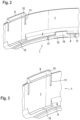
- Figure 2 shows a section of the protective ring 1 according to Figure 1 without fitted base ring 2.
- the base 6 is intended to accommodate the base 3 of the base ring 2 of the gas cylinder.
- the locking arm 9 is located on the outer circumferential wall 7, and the locking arm 10 is located on the inner circumferential edge 8.
- the locking arms 9, 10 are flanked laterally by notches 11, which give the locking arms a certain degree of flexibility and enable the protective ring 1 to be easily pushed onto the base ring 2.
- the length of the notches 11 depends on the degree of flexibility desired and is dependent on the material selected for the protective ring.
- openings 13 which also promote the flexibility of the locking arms 9, 10, but at the same time also provide a drainage option for rain and condensate water.
- Figure 3 shows a detailed section of the protective ring 1 with the outer wall 7, the base area 6 and the inner circumferential edge 8.
- the opening 13 can be seen, the lateral extent of which corresponds to the length of the locking arm 9.
- the locking arm 9 projects inwards by approximately the thickness of the wall 7 so that it can overlap the outer wall 4 of the base ring 2.
- the locking arm 9 has an insertion bevel 12 which makes it easier to slide it onto the base ring 2.
- the notches 11 are located in the immediate vicinity of the locking arm 9, but can also be offset further outwards. Their length is generally about 1 ⁇ 4 to 1 ⁇ 2 the height of the wall 7.
- Figure 4 shows in detail a locking arm 10 arranged on the inner edge 8 of the protective ring 2 with the insertion bevel 12 and the opening 13 located below it, which is located at the transition from the base surface 6 to the inner edge 8.
- the notches 11 are offset laterally outwards. This is necessary for stability reasons in order to ensure a sufficient distance from the opening 13.
- the curved design of the base surface 6 is also clearly visible.
- Figure 5 shows a cross-section of the interaction between protective ring 1 and base ring 2.
- the wall 7 of protective ring 1 lies closely against the outer wall 4 of base ring 2.
- the locking arm 9 engages over base ring 2 at the upper edge of outer wall 4 in the area of a gap between fastening elements 5.
- the opening 13 and an opening 14 in the base surface 3 of base ring 2, which serves for water drainage, can be seen.
- the base ring 2 itself has a vertically rising wall 4 extending from the curved base surface 3. On the inside, the base surface 3 is formed into a rising edge, against which the edge 8 of the protective ring 2 rests.
- the locking element 10 on the inner edge 8 of the protective ring 2 engages over the inner edge of the base ring 2.
- the insertion bevels 12 of the locking arms 9, 10 are clearly visible.
Landscapes
- Engineering & Computer Science (AREA)
- Mechanical Engineering (AREA)
- General Engineering & Computer Science (AREA)
- Details Of Rigid Or Semi-Rigid Containers (AREA)
- Filling Or Discharging Of Gas Storage Vessels (AREA)
Description
- Die Erfindung betrifft einen Schutzring für den Standring einer Gasflasche, wobei der Standring eine umlaufende Wandung aufweist, die über Befestigungselemente mit der Gasflasche verbunden ist, mit einer Grundfläche, deren Innenseite dazu bestimmt ist, den Standring einer Gasflasche aufzunehmen, einer außen um die Grundfläche umlaufenden Wandung zur Anlage an die Wandung des Standrings einer Gasflasche sowie einer Mehrzahl von Rastarmen zu Festlegung des Schutzrings am Standring einer Gasflasche.
- Herkömmliche Gasflaschen bestehen aus einem Zylinder, der am oberen Ende ein Ventil und am unteren Ende einen Standring aufweist. Gasflasche und Standring bestehen in der Regel aus Metall, insbesondere einem für den jeweiligen Inhalt und Druck geeigneten Stahl. Gasflasche und Standring sind in der Regel über Befestigungselemente miteinander verschweißt, wobei zwischen einzelnen Befestigungselementen Durchbrechungen oder Lücken bleiben.
- Standringe haben in der Regel eine um die Standfläche umlaufende Wandung, die in etwa mit dem Verlauf des Druckzylinders fluchtet. Dabei ist die Standfläche ein nach innen umgeformter Teil der Wandung, der in der Regel einen Ring mit einer Breite von etwa 1 cm ausbildet.
- Bedingt durch das Gewicht der Gasflasche und das Material - hochfester Stahl - können die Standringe erhebliche Schäden auf dem Untergrund verursachen. Dies ist insbesondere ein Problem bei im Hausgebrauch eingesetzten Gasflaschen, wie sie beispielsweise in Küchen für Gasherde und auf Terrassen zum Grillen eingesetzt werden.
- Aufgrund der Reibung des Standrings auf dem Untergrund kommt es zudem zu Schäden an der Lackierung des Standrings, die vor allem auch dem Korrosionsschutz dient. In der Folge fangen die Standringe an zu rosten und hinterlassen auf dem Untergrund schwer zu entfernende Rostspuren. Die Korrosionsschäden an Standringen müssen bei der Revision von Gasflaschen aufwendig bearbeitet werden.
- Schutzvorrichtungen für die Standringe von Gasflaschen sind an und für sich bekannt, konnten sich aber bislang nicht durchsetzen, weil sie aufwendig in der Herstellung, schwierig zu handhaben und wenig dauerhaft sind. Insbesondere erwiesen sich die bekannten Vorrichtungen als ungeeignet für die Herstellung im Spritzgussverfahren und die Halterungen am Standring der Gasflasche als unzuverlässig - bei der Handhabung von Gasflaschen lösten sich die Schutzvorrichtungen durch Anecken an Kanten und Reibung am Untergrund immer wieder ab.
- Aus der
US 2010/0147859 A1 ist ein Standsystem für eine Gasflasche nach US-Standard bekannt, bei dem ein Schutzring an einem ringförmigen Kragen angerastet wird. Der Kragen stützt sich auf einem nach außen weisendem Flausch des Standrings der Gasflasche ab. Der Standring ruht in dem Bodenteil des Schutzrings. - Damit liegt der Erfindung die Aufgabe zu Grunde, einen Schutz für Standringe von Gasflaschen bereitzustellen, der die oben geschilderten Probleme behebt. Insbesondere sollen derartige Schutzvorrichtungen einfach herzustellen sein, vorzugsweise im Spritzgussverfahren, einfach anzubringen sein und dauerhaft an der Gasflasche halten.
- Diese Aufgabe wird mit einem Schutzring mit den Merkmalen des Anspruchs 1 gelöst, und dessen Verwendung wie in Anspruch 10 definiert.
- Erfindungsgemäße Schutzringe schützen zum einen den Standring einer Gasflasche vor Schäden durch Kontakt mit dem Untergrund und zum anderen den Untergrund vor Beschädigung durch die Gasflasche. Sie können im Spritzgussverfahren hergestellt werden und sind einfach zu montieren. Aufgrund der Elastizität der Rastarme ist ein sicherer Halt am Standring der Gasflasche sichergestellt, auch bei mechanischer Beanspruchung, wie sie beim Verlagern der Gasflasche auf einem harten Untergrund oder beim Anecken an eine Kante auftritt.
- Der Schutzring bildet im Grunde genommen die äußere Form des Standrings einer Gasflasche - ohne die Befestigungselemente - nach. Auf der Grundfläche kommt die Standfläche des Standrings der Gasflasche zu stehen, an der seitlich umlaufenden Wandung des Standrings liegt die außen umlaufende Wandung des Schutzrings an. An der Innenseite der Grundfläche des Schutzrings kann ein Rand vorgesehen sein, der am Innenrand der Standfläche des Standrings anliegt. Rastarme greifen von der Wandung des Schutzrings über die Wandung des Standrings und/oder vom Innenrand des Schutzrings über die Standfläche des Standrings.
- Insbesondere weist der Schutzring eine Mehrzahl von Rastarmen an der umlaufenden Wandung auf, die die Wandung des Standrings übergreifen. Durch die ringförmige Gestalt des Schutzrings ist allein durch diese Maßnahme ein sicherer Sitz des Schutzrings am Standring sichergestellt. Durch die seitlichen Einschnitte neben den Rastarmen ist eine hohe Flexibilität sichergestellt, die ein einfaches Überstreifen des Schutzrings über den Standring ermöglicht. Die nach innen weisenden Arme der Rastarme schnappen in den zwischen den Befestigungselementen des Standrings vorhandenen Öffnungen oder Lücken an der Oberseite der Wandung des Standrings ein und gewähren einen sicheren Sitz.
- Insbesondere weist der erfindungsgemäße Schutzring so viele Rastarme auf, wie Befestigungselemente bzw. Durchbrechungen zwischen Befestigungselementen des Standrings vorhanden sind. In der Regel sind dies 6 Rastarme.
- Vorzugsweise weisen die erfindungsgemäß verwandten Rastarme an der dem Standring zugewandten Seite eine Einführschräge auf, die das Überstreifen des Schutzrings über den Standring erleichtert. Die Einführschräge verläuft auf der Innenseite des Rastarms von oben nach unten, d.h. in Richtung auf den Fuß der Gasflasche.
- Vorzugsweise fluchten die Rastarme mit der Wandung des Schutzrings, wobei sie aber über den Schutzring hinausragen. Damit bildet die Außenwandung des Schutzrings eine gleichmäßige Rundung aus, die zum einen einen seitlichen Schutz ausbildet und zum anderen verhindert, dass die Rastarme Schaden nehmen, wenn die Gasflasche seitlich im Bereich eines Rastarms aneckt.
- Der erfindungsgemäße Schutzring kann außen und/oder innen mit Rastarmen zur Rasterung mit dem Standring der Gasflasche ausgestattet sein. Außen angeordnete Rastarme befinden sich am oberen Ende der Wandung des Schutzrings. Innen angeordnete Rastarme sind zweckmäßigerweise an einem inneren Rand des Schutzrings, der sich ihnen erstreckt, angeordnet und übergreifen die Grundfläche. In jedem Fall sind die Rastarme elastisch ausgebildet, d.h. sie sind von seitlichen Einschnitten flankiert. Zweckmäßigerweise weisen alle Rastarme Einführschrägen auf.
- Vorzugsweise weist der erfindungsgemäße Schutzring die Rastarme sowohl außen als auch innen auf. In diesem Fall sind die inneren Rastarme gegenüber den äußeren Rastarmen zweckmäßigerweise versetzt.
- Alle Rastarme sind zweckmäßigerweise oberhalb von Durchbrechungen des Schutzrings angeordnet, was zum einen die Flexibilität erhöht und zum anderen eine Abflussmöglichkeit für auf der Grundfläche sich ansammelndes Wasser schafft.
- Die erfindungsgemäßen Schutzringe bestehen zweckmäßigerweise aus einem thermoplastischen Kunststoffmaterial, das eine hinreichende Elastizität bei gleichzeitig hoher Festigkeit besitzt. Bevorzugte Materialien sind Polyalkylene, etwa Polyethylen und Polypropylen, insbesondere HDPE. Diese Materialien sind im Spritzgussverfahren einsetzbar, wobei es das spezielle Design der Schutzringe erlaubt, die Schutzringe "durchtauchend" zu entformen, d.h. ohne Hilfe weiterer mechanischer Elemente oder Werkzeuge. In Frage kommen auch thermoplastische Elastomere mit einer Shore-Härte von 50 bis 85.
- Für die Montage des Schutzrings reicht ein Arbeitsschritt. Da die Rastarme federn und zusätzlich mit Einführschrägen versehen sind, kann der Ring einfach auf den Standring der Gasflasche aufgedrückt werden. Entweder man legt den Ring auf den Boden und drückt die Flasche ein oder man dreht die Flasche um und drückt den Ring auf. Aufgrund der hohen Flexibilität und der federnden Segmente können Fertigungstoleranzen des Standrings der Gasflasche ausgeglichen werden. Die Schutzringe sind auch ohne weiteres wieder abnehmbar, was ein separates Recycling von Schutzring und Flasche ermöglicht.
- Die erfindungsgemäßen Schutzringe sind besonders für die Anbringung an Propangasflaschen für den Hausgebrauch, wie sie zum Heizen und Grillen eingesetzt werden, geeignet. Sie verhindern zuverlässig Rostringe auf der Standfläche und Schäden sowohl am Standring als auch am Untergrund.
- Die Erfindung wird durch die beiliegenden Abbildungen näher erläutert. Es zeigen:
- Fig. 1
- einen erfindungsgemäßen Schutzring zusammen mit dem Standring einer Gasflasche;
- Fig. 2
- einen vergrößerten Ausschnitt des erfindungsgemäßen Schutzrings von
Fig. 1 ; - Fig. 3
- einen äußeren Rastarm des erfindungsgemäßen Schutzrings;
- Fig. 4
- einen inneren Rastarm des erfindungsgemäßen Schutzrings; und
- Fig. 5
- das Zusammenwirken von Schutzring und Standring der Gasflasche anhand einer Schnittzeichnung.
-
Figur 1 zeigt einen erfindungsgemäßen Schutzring 1, aufgerastet auf den Standring 2 einer Gasflasche, die der Übersichtlichkeit halber nicht dargestellt ist. - Der Standring 2 weist eine Standfläche 3 auf, die von einer Außenwandung 4 umgeben ist. Die Außenwandung 4 weist 6 einzelne Befestigungselemente 5 auf, die nach innen eingewölbt sind und die Verbindung zur Gasflasche herstellen. In der Regel sind Gasflasche und Standring 2 aus Metall gefertigt und über die Befestigungselemente 5 miteinander verschweißt. Die relativ hohe Außenwandung 4 verleiht zum einen dem Standring 2 Stabilität und bewahrt zum anderen den gewölbten Flaschenboden vor Bodenkontakt. Die Standfläche 3 kann auf ihrer Innenseite von einem kleinen aufgehenden Rand umgeben sein. Dabei kann die Standfläche 3 selbst eben ausgebildet oder mit einer leichten Außenwölbung versehen sein. Im dargestellten Fall weist der Standring 2 sechs Befestigungselemente 5 auf, die gleichmäßig über den Umfang verteilt sind und voneinander beabstandet sind.
- Auf den Standring 2 aufgerastet ist der Schutzring 1, mit einer außen umlaufenden Wandung 7 und einem innen umlaufenden Rand 8. Die Grundfläche 6, die die umlaufende Wandung 7 und den Rand 8 verbindet, ist durch den Standring 2 verdeckt.
- Der Schutzring 1 weist am oberen Ende der umlaufenden Wandung 7 Rastarme 9 auf, die mit der Außenseite der Wandung 7 fluchten und einen nach innen weisenden Vorsprung aufweisen, der über den oberen Rand der Außenwandung 4 des Standrings 2 im Bereich der Lücken zwischen den Befestigungselementen 5 greift.
- Der innere Rand 8 des Schutzrings 1 weist ebenfalls Rastarme 10 auf, die mit dem innen umlaufenden Rand 8 des Standrings 2 zusammenwirken.
- Alle Rastarme 9, 10 sind von Einschnitten 11 flankiert.
-
Figur 2 zeigt einen Ausschnitt des Schutzrings 1 gemäßFigur 1 ohne eingepassten Standring 2. Zu erkennen ist die leicht gewölbte Grundfläche 6 mit der außen umlaufenden Wandung 7 und dem innen umlaufenden Rand 8. Die Grundfläche 6 ist dazu bestimmt, die Standfläche 3 des Standrings 2 der Gasflasche aufzunehmen. - An der außen umlaufenden Wandung 7 befindet sich der Rastarm 9, am innen umlaufenden Rand 8 der Rastarm 10. Die Rastarme 9, 10 sind seitlich von Einschnitten 11 flankiert, die den Rastarmen eine gewisse Flexibilität verleihen und das problemlose Aufschieben des Schutzrings 1 auf den Standring 2 ermöglichen. Die Länge der Einschnitte 11 bemisst sich nach dem Grad der erwünschten Flexibilität und ist abhängig von dem für den Schutzring gewählten Material.
- Unterhalb der Rastarme 9, 10 befinden sich im Bereich des Übergangs der Grundfläche 6 zur äußeren Wandung 7 bzw. zum innen umlaufenden Rand 8 (verdeckt) Durchbrechungen 13, die ebenfalls die Flexibilität der Rastarme 9,10 fördern, zugleich aber auch eine Abflussmöglichkeit für Regen- und Kondenswasser bieten.
-
Figur 3 zeigt im Detail einen Ausschnitt aus dem Schutzring 1 mit der Außenwandung 7, der Grundfläche 6 und dem innen umlaufenden Rand 8. Zu erkennen ist die Durchbrechung 13, die in ihrer seitlichen Ausdehnung der Länge des Rastarms 9 entspricht. Rastarm 9 ragt um etwa die Wandstärke der Wandung 7 nach innen, sodass er die Außenwandung 4 des Standrings 2 übergreifen kann. Zur Innenseite hin weist der Rastarm 9 eine Einführschräge 12 auf, die das Aufschieben auf den Standring 2 erleichtert. Die Einschnitte 11 befinden sich in unmittelbarer Nachbarschaft zum Rastarm 9, können aber auch weiter nach außen versetzt sein. Ihre Länge beträgt generell etwa ¼ bis ½ der Höhe der Wandung 7. -
Figur 4 zeigt im Detail einen am inneren Rand 8 des Schutzrings 2 angeordneten Rastarm 10 mit der Einführschräge 12 und der darunter befindlichen Durchbrechung 13, die sich am Übergang der Grundfläche 6 zum inneren Rand 8 befindet. Im dargestellten Fall sind die Einschnitte 11 seitlich nach außen versetzt. Dies ist aus Stabilitätsgründen erforderlich, um einen hinreichenden Abstand zur Durchbrechung 13 herzu dasstellen. Deutlich zu erkennen ist auch die gekrümmte Ausführung der Grundfläche 6. - Es ist vorteilhaft, an der Wandung 7 und am Rand 8 angeordneten Rastarme 9,10 gegeneinander versetzen, da dies die Verrastung mit dem Standring 2 erleichtert.
-
Figur 5 zeigt im Schnitt das Zusammenwirken von Schutzring 1 und Standring 2. Die Wandung 7 des Schutzrings 1 liegt eng an der Außenwandung 4 des Standrings 2 an. Der Rastarm 9 übergreift den Standring 2 am oberen Rand der Außenwandung 4 im Bereich einer Lücke zwischen den Befestigungselementen 5. Zu erkennen ist die Durchbrechung 13 und eine Durchbrechung 14 in der Standfläche 3 des Standrings 2, die dem Wasserabfluss dient. - Der Standring 2 selbst hat eine senkrecht aufgehende Wandung 4, die von der gewölbten Stand Fläche 3 ausgeht. Auf der Innenseite ist die Standfläche 3 zu einem aufgehenden Rand umgeformt, an dem der Rand 8 des Schutzrings 2 anliegt. Das Rastelement 10 am inneren Rand 8 des Schutzrings 2 greift über den inneren Rand des Standrings 2. Deutlich zu erkennen sind die Einführschrägen 12 der Rastarme 9, 10.
Claims (10)
- Schutzring für den Standring (2) einer Gasflasche, wobei der Standring (2) eine Standfläche (3) und eine umlaufende Außenwandung (4) aufweist, die über Befestigungselemente (5) mit der Gasflasche verbunden ist, mit• einer Grundfläche (6), deren Innenseite dazu bestimmt ist, die Standfläche (3) des Standrings (2) der Gasflasche aufzunehmen,• einem innen um die Grundfläche (6) umlaufenden Rand (8)• eine außen um die Grundfläche (6) umlaufende Wandung (7), die zur Anlage an die Außenwandung (4) des Standrings einer Gasflasche bestimmt ist• einer Mehrzahl von Feststellelementen, wobei die Feststellelemente elastische Rastarme (9) sind, die beidseitig von Einschnitten (11) in den Schutzring (1) flankiert sind, wobei die Rastarme (9) an der umlaufenden Wandung (4) des Schutzrings (1) angeordnet sind, dadurch gekennzeichnet, dass die Rastarme (9) dazu bestimmt sind die Außenwandung (4) des Standrings (2) zu übergreifen und den Schutzring (1) am Standring (2) der Gasflasche festzulegen, wobei die Rastarme (9) nach innen weisende Arme aufweisen, die dazu bestimmt sind in den zwischen den Befestigungselementen (5) des Standrings (2), vorhandene Öffnungen oder Lücken einzuschnappen.
- Schutzring nach Anspruch 1, dadurch gekennzeichnet, dass die Rastarme (9, 10) an ihrer dem Standring (2) zugewandten Seite Einführschrägen (12) aufweisen.
- Schutzring nach Anspruch 1, dadurch gekennzeichnet, dass die Rastarme (9) an ihrer Außenseite mit der Wandung (7) des Schutzrings (1) fluchten und über die Wandung (7) hinausragen.
- Schutzring nach Anspruch 3, dadurch gekennzeichnet, dass unterhalb der Rastarme (9) im Bereich des Übergangs der Grundfläche (6) zur Wandung (7) des Schutzrings (1) Durchbrechungen (13) angeordnet sind, die in ihrer Länge der Ausdehnung der Rastarme (9) entsprechen.
- Schutzring nach einem der vorstehenden Ansprüche, dadurch gekennzeichnet, dass er einen innen um die Grundfläche (6) umlaufenden Rand (8) aufweist, der zur Anlage an den Innenrand des Standrings (2) einer Gasflasche bestimmt ist.
- Schutzring nach Anspruch 5, dadurch gekennzeichnet, dass unterhalb der Rastarme (10) im Bereich des Übergangs der Grundfläche (6) zum Rand (8) des Schutzrings (1) Durchbrechungen (13) angeordnet sind, die in ihrer Länge der Ausdehnung der Rastarme (10) entsprechen.
- Schutzring nach einem der vorstehenden Ansprüche, gefertigt im Spritzgussverfahren aus Polyalkylen.
- Gasflasche mit einem Schutzring (1) nach einem der Ansprüche 1 bis 8.
- Propangasflasche nach Anspruch 9.
- Verwendung von Schutzringen nach einem der Ansprüche 1 bis 7 zum Schutz von Standringen von Gasflaschen.
Applications Claiming Priority (2)
| Application Number | Priority Date | Filing Date | Title |
|---|---|---|---|
| DE202015105945.0U DE202015105945U1 (de) | 2015-11-06 | 2015-11-06 | Schutzring für Gasflaschen |
| PCT/EP2016/075930 WO2017076736A1 (de) | 2015-11-06 | 2016-10-27 | Schutzring für gasflaschen |
Publications (2)
| Publication Number | Publication Date |
|---|---|
| EP3371507A1 EP3371507A1 (de) | 2018-09-12 |
| EP3371507B1 true EP3371507B1 (de) | 2025-05-21 |
Family
ID=55638325
Family Applications (1)
| Application Number | Title | Priority Date | Filing Date |
|---|---|---|---|
| EP16798418.6A Active EP3371507B1 (de) | 2015-11-06 | 2016-10-27 | Schutzring für gasflaschen |
Country Status (5)
| Country | Link |
|---|---|
| EP (1) | EP3371507B1 (de) |
| DE (1) | DE202015105945U1 (de) |
| PL (1) | PL3371507T3 (de) |
| PT (1) | PT3371507T (de) |
| WO (1) | WO2017076736A1 (de) |
Families Citing this family (3)
| Publication number | Priority date | Publication date | Assignee | Title |
|---|---|---|---|---|
| US11473733B2 (en) * | 2019-02-27 | 2022-10-18 | Amtrol Licensing Inc. | Foot for a portable pressurized gas cylinder |
| CN113357527B (zh) * | 2021-07-02 | 2023-02-17 | 兰州空间技术物理研究所 | 一种用于大载重细长型缠绕气瓶的柔性紧固安装底罩 |
| USD1064179S1 (en) | 2022-08-05 | 2025-02-25 | Amtrol Licensing Inc. | Cylinder stand |
Family Cites Families (4)
| Publication number | Priority date | Publication date | Assignee | Title |
|---|---|---|---|---|
| US4907712A (en) * | 1988-09-19 | 1990-03-13 | Stempin David R | Tank stabilizer |
| DE60035407D1 (de) * | 2000-02-09 | 2007-08-16 | Amtrol Inc | Volle Auskleidung für Gaszylinder |
| US8215517B2 (en) * | 2008-12-17 | 2012-07-10 | Amtrol Licensing, Inc. | Compressed gas cylinder having conductive polymeric foot ring |
| ITMI20150062U1 (it) * | 2015-03-17 | 2016-09-17 | Faber Ind Spa | Bombola da gas |
-
2015
- 2015-11-06 DE DE202015105945.0U patent/DE202015105945U1/de not_active Expired - Lifetime
-
2016
- 2016-10-27 WO PCT/EP2016/075930 patent/WO2017076736A1/de not_active Ceased
- 2016-10-27 PT PT167984186T patent/PT3371507T/pt unknown
- 2016-10-27 EP EP16798418.6A patent/EP3371507B1/de active Active
- 2016-10-27 PL PL16798418.6T patent/PL3371507T3/pl unknown
Also Published As
| Publication number | Publication date |
|---|---|
| DE202015105945U1 (de) | 2016-03-16 |
| EP3371507A1 (de) | 2018-09-12 |
| PT3371507T (pt) | 2025-08-25 |
| PL3371507T3 (pl) | 2025-09-29 |
| WO2017076736A1 (de) | 2017-05-11 |
Similar Documents
| Publication | Publication Date | Title |
|---|---|---|
| BE1018955A5 (de) | Ventil fur einen behalter zur abgabe von unter druck stehendem fluid. | |
| WO2014044375A1 (de) | Palettencontainer | |
| DE1411626A1 (de) | Einwandiger Metallbehaelter,insbesondere Bierfass | |
| EP2117944B1 (de) | Behälter | |
| DE102015016814A1 (de) | Transport- und Lagerbehälter für Flüssigkeiten | |
| DE102012104395A1 (de) | Hochfester Rohrleitungsgewindeschutz | |
| WO2017076736A1 (de) | Schutzring für gasflaschen | |
| EP2000681A2 (de) | Stützhülse | |
| WO2016146517A1 (de) | Federträger | |
| EP1902181B1 (de) | Schachtoberteil | |
| EP3237786B1 (de) | Dichteinsatz für einen wasserablauf | |
| WO2003016154A1 (de) | Einweg-keg | |
| EP2369215A1 (de) | Steckverbindung | |
| EP3428540B1 (de) | Kochplattenvorrichtung mit einer kochplatte und kochfeld | |
| DE102015006691A1 (de) | Schutzvorrichtung für den Fußbereich von Gasflaschen mit Standfußanordnung | |
| AT236860B (de) | Metallener, einwandiger Behälter | |
| EP1722145B1 (de) | Rohrelement mit Schutzelement | |
| DE102009053652A1 (de) | Dach-Durchführung für eine Rohrleitung mit Kugelkopf und Kondensatablauf | |
| DE19949697B4 (de) | Vorrichtung zum Verschliessen von Rohrenden | |
| DE611326C (de) | Doppelwandiges Metallfass | |
| AT509798A1 (de) | Modulare schlauchbrücke | |
| EP3631269B1 (de) | Kupplung zur herstellung einer pressverbindung zwischen zwei rohren | |
| EP3037695A1 (de) | Dichteinsatz für einen wasserablauf | |
| CH639910A5 (en) | Transporting container for liquids, in particular beverages | |
| EP3412371A1 (de) | Bandlagervorrichtung |
Legal Events
| Date | Code | Title | Description |
|---|---|---|---|
| STAA | Information on the status of an ep patent application or granted ep patent |
Free format text: STATUS: UNKNOWN |
|
| STAA | Information on the status of an ep patent application or granted ep patent |
Free format text: STATUS: THE INTERNATIONAL PUBLICATION HAS BEEN MADE |
|
| PUAI | Public reference made under article 153(3) epc to a published international application that has entered the european phase |
Free format text: ORIGINAL CODE: 0009012 |
|
| STAA | Information on the status of an ep patent application or granted ep patent |
Free format text: STATUS: REQUEST FOR EXAMINATION WAS MADE |
|
| 17P | Request for examination filed |
Effective date: 20180606 |
|
| AK | Designated contracting states |
Kind code of ref document: A1 Designated state(s): AL AT BE BG CH CY CZ DE DK EE ES FI FR GB GR HR HU IE IS IT LI LT LU LV MC MK MT NL NO PL PT RO RS SE SI SK SM TR |
|
| AX | Request for extension of the european patent |
Extension state: BA ME |
|
| DAV | Request for validation of the european patent (deleted) | ||
| DAX | Request for extension of the european patent (deleted) | ||
| STAA | Information on the status of an ep patent application or granted ep patent |
Free format text: STATUS: EXAMINATION IS IN PROGRESS |
|
| 17Q | First examination report despatched |
Effective date: 20210512 |
|
| GRAP | Despatch of communication of intention to grant a patent |
Free format text: ORIGINAL CODE: EPIDOSNIGR1 |
|
| STAA | Information on the status of an ep patent application or granted ep patent |
Free format text: STATUS: GRANT OF PATENT IS INTENDED |
|
| INTG | Intention to grant announced |
Effective date: 20241217 |
|
| GRAS | Grant fee paid |
Free format text: ORIGINAL CODE: EPIDOSNIGR3 |
|
| GRAA | (expected) grant |
Free format text: ORIGINAL CODE: 0009210 |
|
| STAA | Information on the status of an ep patent application or granted ep patent |
Free format text: STATUS: THE PATENT HAS BEEN GRANTED |
|
| AK | Designated contracting states |
Kind code of ref document: B1 Designated state(s): AL AT BE BG CH CY CZ DE DK EE ES FI FR GB GR HR HU IE IS IT LI LT LU LV MC MK MT NL NO PL PT RO RS SE SI SK SM TR |
|
| REG | Reference to a national code |
Ref country code: GB Ref legal event code: FG4D Free format text: NOT ENGLISH |
|
| REG | Reference to a national code |
Ref country code: DE Ref legal event code: R081 Ref document number: 502016016983 Country of ref document: DE Owner name: SCHMITT PROF. MOEHLMANN & COLLEGEN WIRTSCHAFTS, DE Free format text: FORMER OWNER: ANMELDERANGABEN UNKLAR / UNVOLLSTAENDIG, 80297 MUENCHEN, DE |
|
| REG | Reference to a national code |
Ref country code: CH Ref legal event code: EP |
|
| REG | Reference to a national code |
Ref country code: DE Ref legal event code: R096 Ref document number: 502016016983 Country of ref document: DE |
|
| REG | Reference to a national code |
Ref country code: IE Ref legal event code: FG4D Free format text: LANGUAGE OF EP DOCUMENT: GERMAN |
|
| REG | Reference to a national code |
Ref country code: DE Ref legal event code: R081 Ref document number: 502016016983 Country of ref document: DE Owner name: SCHMITT PROF. MOEHLMANN & COLLEGEN WIRTSCHAFTS, DE Free format text: FORMER OWNER: SCHMITT PROF. MOEHLMANN & COLLEGEN WIRTSCHAFTSKANZLEI-INSOLVENZVERWALTER AKTIENGESELLSCHAFT, 08056 ZWICKAU, DE |
|
| P01 | Opt-out of the competence of the unified patent court (upc) registered |
Free format text: CASE NUMBER: APP_29697/2025 Effective date: 20250623 |
|
| REG | Reference to a national code |
Ref country code: PT Ref legal event code: SC4A Ref document number: 3371507 Country of ref document: PT Date of ref document: 20250825 Kind code of ref document: T Free format text: AVAILABILITY OF NATIONAL TRANSLATION Effective date: 20250818 |
|
| RAP4 | Party data changed (patent owner data changed or rights of a patent transferred) |
Owner name: SCHMITT PROF. MOEHLMANN & COLLEGENWIRTSCHAFTSKANZLEI - INSOLVENZVERWALTER GMBH |
|
| REG | Reference to a national code |
Ref country code: NL Ref legal event code: MP Effective date: 20250521 |
|
| PG25 | Lapsed in a contracting state [announced via postgrant information from national office to epo] |
Ref country code: ES Free format text: LAPSE BECAUSE OF FAILURE TO SUBMIT A TRANSLATION OF THE DESCRIPTION OR TO PAY THE FEE WITHIN THE PRESCRIBED TIME-LIMIT Effective date: 20250521 Ref country code: FI Free format text: LAPSE BECAUSE OF FAILURE TO SUBMIT A TRANSLATION OF THE DESCRIPTION OR TO PAY THE FEE WITHIN THE PRESCRIBED TIME-LIMIT Effective date: 20250521 |
|
| REG | Reference to a national code |
Ref country code: LT Ref legal event code: MG9D |
|
| PG25 | Lapsed in a contracting state [announced via postgrant information from national office to epo] |
Ref country code: GR Free format text: LAPSE BECAUSE OF FAILURE TO SUBMIT A TRANSLATION OF THE DESCRIPTION OR TO PAY THE FEE WITHIN THE PRESCRIBED TIME-LIMIT Effective date: 20250822 Ref country code: NO Free format text: LAPSE BECAUSE OF FAILURE TO SUBMIT A TRANSLATION OF THE DESCRIPTION OR TO PAY THE FEE WITHIN THE PRESCRIBED TIME-LIMIT Effective date: 20250821 |
|
| PG25 | Lapsed in a contracting state [announced via postgrant information from national office to epo] |
Ref country code: NL Free format text: LAPSE BECAUSE OF FAILURE TO SUBMIT A TRANSLATION OF THE DESCRIPTION OR TO PAY THE FEE WITHIN THE PRESCRIBED TIME-LIMIT Effective date: 20250521 |
|
| PG25 | Lapsed in a contracting state [announced via postgrant information from national office to epo] |
Ref country code: BG Free format text: LAPSE BECAUSE OF FAILURE TO SUBMIT A TRANSLATION OF THE DESCRIPTION OR TO PAY THE FEE WITHIN THE PRESCRIBED TIME-LIMIT Effective date: 20250521 |
|
| PG25 | Lapsed in a contracting state [announced via postgrant information from national office to epo] |
Ref country code: HR Free format text: LAPSE BECAUSE OF FAILURE TO SUBMIT A TRANSLATION OF THE DESCRIPTION OR TO PAY THE FEE WITHIN THE PRESCRIBED TIME-LIMIT Effective date: 20250521 |
|
| PG25 | Lapsed in a contracting state [announced via postgrant information from national office to epo] |
Ref country code: RS Free format text: LAPSE BECAUSE OF FAILURE TO SUBMIT A TRANSLATION OF THE DESCRIPTION OR TO PAY THE FEE WITHIN THE PRESCRIBED TIME-LIMIT Effective date: 20250821 |
|
| PG25 | Lapsed in a contracting state [announced via postgrant information from national office to epo] |
Ref country code: IS Free format text: LAPSE BECAUSE OF FAILURE TO SUBMIT A TRANSLATION OF THE DESCRIPTION OR TO PAY THE FEE WITHIN THE PRESCRIBED TIME-LIMIT Effective date: 20250921 |
|
| PG25 | Lapsed in a contracting state [announced via postgrant information from national office to epo] |
Ref country code: LV Free format text: LAPSE BECAUSE OF FAILURE TO SUBMIT A TRANSLATION OF THE DESCRIPTION OR TO PAY THE FEE WITHIN THE PRESCRIBED TIME-LIMIT Effective date: 20250521 |
|
| PGFP | Annual fee paid to national office [announced via postgrant information from national office to epo] |
Ref country code: PT Payment date: 20251016 Year of fee payment: 10 |
|
| REG | Reference to a national code |
Ref country code: AT Ref legal event code: PC Ref document number: 1797001 Country of ref document: AT Kind code of ref document: T Owner name: SCHMITT PROF. MOEHLMANN & COLLEGEN WIRTSCHAFTSK, DE Effective date: 20251103 |
|
| PGFP | Annual fee paid to national office [announced via postgrant information from national office to epo] |
Ref country code: DE Payment date: 20251021 Year of fee payment: 10 |
|
| PG25 | Lapsed in a contracting state [announced via postgrant information from national office to epo] |
Ref country code: DK Free format text: LAPSE BECAUSE OF FAILURE TO SUBMIT A TRANSLATION OF THE DESCRIPTION OR TO PAY THE FEE WITHIN THE PRESCRIBED TIME-LIMIT Effective date: 20250521 Ref country code: SM Free format text: LAPSE BECAUSE OF FAILURE TO SUBMIT A TRANSLATION OF THE DESCRIPTION OR TO PAY THE FEE WITHIN THE PRESCRIBED TIME-LIMIT Effective date: 20250521 |
|
| PGFP | Annual fee paid to national office [announced via postgrant information from national office to epo] |
Ref country code: AT Payment date: 20251022 Year of fee payment: 10 |
|
| PGFP | Annual fee paid to national office [announced via postgrant information from national office to epo] |
Ref country code: TR Payment date: 20251020 Year of fee payment: 10 |
|
| PG25 | Lapsed in a contracting state [announced via postgrant information from national office to epo] |
Ref country code: CZ Free format text: LAPSE BECAUSE OF FAILURE TO SUBMIT A TRANSLATION OF THE DESCRIPTION OR TO PAY THE FEE WITHIN THE PRESCRIBED TIME-LIMIT Effective date: 20250521 |
|
| PGFP | Annual fee paid to national office [announced via postgrant information from national office to epo] |
Ref country code: PL Payment date: 20251016 Year of fee payment: 10 |
|
| PG25 | Lapsed in a contracting state [announced via postgrant information from national office to epo] |
Ref country code: EE Free format text: LAPSE BECAUSE OF FAILURE TO SUBMIT A TRANSLATION OF THE DESCRIPTION OR TO PAY THE FEE WITHIN THE PRESCRIBED TIME-LIMIT Effective date: 20250521 |
|
| PG25 | Lapsed in a contracting state [announced via postgrant information from national office to epo] |
Ref country code: SK Free format text: LAPSE BECAUSE OF FAILURE TO SUBMIT A TRANSLATION OF THE DESCRIPTION OR TO PAY THE FEE WITHIN THE PRESCRIBED TIME-LIMIT Effective date: 20250521 Ref country code: RO Free format text: LAPSE BECAUSE OF FAILURE TO SUBMIT A TRANSLATION OF THE DESCRIPTION OR TO PAY THE FEE WITHIN THE PRESCRIBED TIME-LIMIT Effective date: 20250521 |
|
| PG25 | Lapsed in a contracting state [announced via postgrant information from national office to epo] |
Ref country code: IT Free format text: LAPSE BECAUSE OF FAILURE TO SUBMIT A TRANSLATION OF THE DESCRIPTION OR TO PAY THE FEE WITHIN THE PRESCRIBED TIME-LIMIT Effective date: 20250521 |
|
| REG | Reference to a national code |
Ref country code: DE Ref legal event code: R097 Ref document number: 502016016983 Country of ref document: DE |
|
| PLBE | No opposition filed within time limit |
Free format text: ORIGINAL CODE: 0009261 |
|
| STAA | Information on the status of an ep patent application or granted ep patent |
Free format text: STATUS: NO OPPOSITION FILED WITHIN TIME LIMIT |
|
| REG | Reference to a national code |
Ref country code: CH Ref legal event code: L10 Free format text: ST27 STATUS EVENT CODE: U-0-0-L10-L00 (AS PROVIDED BY THE NATIONAL OFFICE) Effective date: 20260402 |
|
| 26N | No opposition filed |
Effective date: 20260224 |
|
| REG | Reference to a national code |
Ref country code: CH Ref legal event code: H13 Free format text: ST27 STATUS EVENT CODE: U-0-0-H10-H13 (AS PROVIDED BY THE NATIONAL OFFICE) Effective date: 20260527 |
|
| PG25 | Lapsed in a contracting state [announced via postgrant information from national office to epo] |
Ref country code: LU Free format text: LAPSE BECAUSE OF NON-PAYMENT OF DUE FEES Effective date: 20251027 |
|
| REG | Reference to a national code |
Ref country code: BE Ref legal event code: MM Effective date: 20251031 |
|
| GBPC | Gb: european patent ceased through non-payment of renewal fee |
Effective date: 20251027 |
|
| PG25 | Lapsed in a contracting state [announced via postgrant information from national office to epo] |
Ref country code: LT Free format text: LAPSE BECAUSE OF FAILURE TO SUBMIT A TRANSLATION OF THE DESCRIPTION OR TO PAY THE FEE WITHIN THE PRESCRIBED TIME-LIMIT Effective date: 20250521 |
|
| PG25 | Lapsed in a contracting state [announced via postgrant information from national office to epo] |
Ref country code: MC Free format text: LAPSE BECAUSE OF FAILURE TO SUBMIT A TRANSLATION OF THE DESCRIPTION OR TO PAY THE FEE WITHIN THE PRESCRIBED TIME-LIMIT Effective date: 20250521 |
|
| PG25 | Lapsed in a contracting state [announced via postgrant information from national office to epo] |
Ref country code: GB Free format text: LAPSE BECAUSE OF NON-PAYMENT OF DUE FEES Effective date: 20251027 |
|
| PG25 | Lapsed in a contracting state [announced via postgrant information from national office to epo] |
Ref country code: BE Free format text: LAPSE BECAUSE OF NON-PAYMENT OF DUE FEES Effective date: 20251031 Ref country code: CH Free format text: LAPSE BECAUSE OF NON-PAYMENT OF DUE FEES Effective date: 20251031 |
|
| PG25 | Lapsed in a contracting state [announced via postgrant information from national office to epo] |
Ref country code: FR Free format text: LAPSE BECAUSE OF NON-PAYMENT OF DUE FEES Effective date: 20251031 |
|
| PG25 | Lapsed in a contracting state [announced via postgrant information from national office to epo] |
Ref country code: SE Free format text: LAPSE BECAUSE OF FAILURE TO SUBMIT A TRANSLATION OF THE DESCRIPTION OR TO PAY THE FEE WITHIN THE PRESCRIBED TIME-LIMIT Effective date: 20250521 |