EP3372343A1 - Anordnung aus einem reaktionsmomente ableitenden stützarm und einem drehschrauber - Google Patents
Anordnung aus einem reaktionsmomente ableitenden stützarm und einem drehschrauber Download PDFInfo
- Publication number
- EP3372343A1 EP3372343A1 EP18159366.6A EP18159366A EP3372343A1 EP 3372343 A1 EP3372343 A1 EP 3372343A1 EP 18159366 A EP18159366 A EP 18159366A EP 3372343 A1 EP3372343 A1 EP 3372343A1
- Authority
- EP
- European Patent Office
- Prior art keywords
- support arm
- transmission housing
- mounting flange
- screwdriver
- pin
- Prior art date
- Legal status (The legal status is an assumption and is not a legal conclusion. Google has not performed a legal analysis and makes no representation as to the accuracy of the status listed.)
- Granted
Links
Images

Classifications
-
- B—PERFORMING OPERATIONS; TRANSPORTING
- B25—HAND TOOLS; PORTABLE POWER-DRIVEN TOOLS; MANIPULATORS
- B25B—TOOLS OR BENCH DEVICES NOT OTHERWISE PROVIDED FOR, FOR FASTENING, CONNECTING, DISENGAGING OR HOLDING
- B25B21/00—Portable power-driven screw or nut setting or loosening tools; Attachments for drilling apparatus serving the same purpose
-
- B—PERFORMING OPERATIONS; TRANSPORTING
- B25—HAND TOOLS; PORTABLE POWER-DRIVEN TOOLS; MANIPULATORS
- B25B—TOOLS OR BENCH DEVICES NOT OTHERWISE PROVIDED FOR, FOR FASTENING, CONNECTING, DISENGAGING OR HOLDING
- B25B23/00—Details of, or accessories for, spanners, wrenches, screwdrivers
- B25B23/0078—Reaction arms
-
- B—PERFORMING OPERATIONS; TRANSPORTING
- B25—HAND TOOLS; PORTABLE POWER-DRIVEN TOOLS; MANIPULATORS
- B25B—TOOLS OR BENCH DEVICES NOT OTHERWISE PROVIDED FOR, FOR FASTENING, CONNECTING, DISENGAGING OR HOLDING
- B25B27/00—Hand tools, specially adapted for fitting together or separating parts or objects whether or not involving some deformation, not otherwise provided for
- B25B27/14—Hand tools, specially adapted for fitting together or separating parts or objects whether or not involving some deformation, not otherwise provided for for assembling objects other than by press fit or detaching same
-
- B—PERFORMING OPERATIONS; TRANSPORTING
- B25—HAND TOOLS; PORTABLE POWER-DRIVEN TOOLS; MANIPULATORS
- B25F—COMBINATION OR MULTI-PURPOSE TOOLS NOT OTHERWISE PROVIDED FOR; DETAILS OR COMPONENTS OF PORTABLE POWER-DRIVEN TOOLS NOT PARTICULARLY RELATED TO THE OPERATIONS PERFORMED AND NOT OTHERWISE PROVIDED FOR
- B25F5/00—Details or components of portable power-driven tools not particularly related to the operations performed and not otherwise provided for
- B25F5/001—Gearings, speed selectors, clutches or the like specially adapted for rotary tools
-
- B—PERFORMING OPERATIONS; TRANSPORTING
- B25—HAND TOOLS; PORTABLE POWER-DRIVEN TOOLS; MANIPULATORS
- B25F—COMBINATION OR MULTI-PURPOSE TOOLS NOT OTHERWISE PROVIDED FOR; DETAILS OR COMPONENTS OF PORTABLE POWER-DRIVEN TOOLS NOT PARTICULARLY RELATED TO THE OPERATIONS PERFORMED AND NOT OTHERWISE PROVIDED FOR
- B25F5/00—Details or components of portable power-driven tools not particularly related to the operations performed and not otherwise provided for
- B25F5/02—Construction of casings, bodies or handles
- B25F5/025—Construction of casings, bodies or handles with torque reaction bars for rotary tools
-
- F—MECHANICAL ENGINEERING; LIGHTING; HEATING; WEAPONS; BLASTING
- F16—ENGINEERING ELEMENTS AND UNITS; GENERAL MEASURES FOR PRODUCING AND MAINTAINING EFFECTIVE FUNCTIONING OF MACHINES OR INSTALLATIONS; THERMAL INSULATION IN GENERAL
- F16H—GEARING
- F16H57/00—General details of gearing
- F16H57/02—Gearboxes; Mounting gearing therein
- F16H2057/02026—Connection of auxiliaries with a gear case; Mounting of auxiliaries on the gearbox
-
- F—MECHANICAL ENGINEERING; LIGHTING; HEATING; WEAPONS; BLASTING
- F16—ENGINEERING ELEMENTS AND UNITS; GENERAL MEASURES FOR PRODUCING AND MAINTAINING EFFECTIVE FUNCTIONING OF MACHINES OR INSTALLATIONS; THERMAL INSULATION IN GENERAL
- F16H—GEARING
- F16H57/00—General details of gearing
- F16H57/02—Gearboxes; Mounting gearing therein
Definitions
- the invention relates to an arrangement of a reaction torque dissipating support arm and a screwdriver, which has a drive part and a transmission housing with an out leading out of the transmission housing output shaft and is provided around the gear housing around with an outer spline teeth whose backwards to a the gear housing extending around the circumference of the groove whose groove base is at a diameter which is smaller than the diameter described by the tips of the teeth, wherein the support arm has a mounting portion with an annular mounting flange and an internal spline, as well as a laterally offset to the output shaft arranged, can be applied against an external abutment support leg, wherein the spline of the mounting flange with the spline of the transmission housing cooperates such that the support arm is rotationally fixed to the transmission housing, wherein de m mounting flange is arranged a locking element which can assume a blocking or a release position, and wherein the support arm is fixed in the locking position in the longitudinal direction of the transmission housing.
- screwdrivers are usually held by an operator by a handle.
- the often considerable moment of reaction arising during the screwing process can be dissipated by means of a support arm fixed non-rotatably to the screwdriver.
- the support arm on an existing solid component, such as an adjacent screw, rest or support it.
- the adjacent screw then serves as an abutment.
- a transmission of reaction moments on the operator of the rotary wrench, for example via the handle avoided.
- the reaction moments occurring are difficult to predict in advance and can lead to an incalculable risk to the operator, and cause about a kickback of the rotary wrench.
- the reliability of the rotary wrench is increased by a corresponding support arm assembly on the screwdriver. Furthermore, this results in a more comfortable use of the rotary screwdriver.
- the support arm has an annular mounting flange with an internal toothing and can be pushed onto a transmission housing surrounding the output shaft with a corresponding external toothing. As a result, the support arm is rotationally fixed relative to the transmission housing.
- B arranged in a tooth or tooth base of the internal toothing a radially displaceably mounted ball.
- a spring-biased actuating pin receives the ball at least partially in a backdrop. In the actuated state of the actuating pin the ball jammed against the tooth flanks or tooth tips of the external teeth, and thus clamped the gear housing axially relative to the support arm.
- the disadvantage here is that the attachment in the longitudinal direction is based solely on clamping or friction forces. As a result, there is a risk that the fastening position is released with appropriate pressure or tensile load of the arm relative to the screwdriver, and the support arm slips together with the mounting flange of the gear housing of the rotary screwdriver. It also comes with such a clamping and friction-based attachment to increased material wear due to abrasion.
- the invention has for its object to provide an arrangement of a reaction torque dissipating support arm and a screwdriver, which allows a reliable, secure and low-wear attachment of the support arm to the screwdriver.
- the arrangement according to the invention initially consists of a reaction arm dissipating support arm and a screwdriver.
- the screwdriver has a drive part and a transmission housing with an outgoing from the gear housing output shaft.
- the screwdriver can have further components. These include a handle, in the case of an electrically driven rotary wrench a battery module, also controls and visual and / or audible indicators. But the invention can also be realized on a pneumatically driven screwdriver.
- the support arm has a mounting portion with an annular mounting flange and an internal spline, as well as an engageable against an external abutment support portion with a support leg which is arranged laterally offset from the output shaft.
- the internal spline on the mounting flange cooperates with the outer spline on the transmission housing such that the support arm is rotationally fixed to the transmission housing.
- a locking element On the mounting flange, a locking element is arranged, which can assume a blocking or a release position.
- the support arm is fixed in the blocking position in the longitudinal direction of the transmission housing.
- the locking element In the locking position, the locking element extends at least partially into the groove and thus locks the support arm in the longitudinal direction of the transmission housing, in a defined longitudinal position.
- a rotary shaft often used anyway on the gear housing groove is used to lock the support arm in a unique longitudinal position.
- the attachment is thus in contrast to the solution of the DE 10 2009 005 997 A1 not on a force-locking jamming and shows even in continuous use a little wear. It is also conceivable to arrange a plurality of such fixing devices circumferentially of the mounting flange, for example, to improve the positive locking again.
- the locking element is part of a further comprising an actuator fixing device, wherein the actuating element has a tangentially displaceable within the mounting flange, biased against a compression spring pin having a slot or recess for partially receiving the locking element in the release position.
- the tangential arrangement of the actuating element or pin facilitates the accessibility of the pin when actuated by the operator. From the prior art, an axial arrangement of such a pin is known. This can lead to a more difficult accessibility of the pen, depending on the screw situation. The operation of the pen may also be necessary in an acute stersituation, for example, for readjustment of the support arm. In particular, in tight spaces, it is advantageous to be able to actuate the pin from the side.
- the actuating element consists of the guided in a bore of the mounting flange pin and the end of the pin forming, widened head. Due to the bipartite nature of the actuating element, on the one hand a clean guidance of the actuating element in the bore is ensured, but on the other hand also an easy operability from outside.
- the pin and the head may be integral, or screwed together, for example.
- the head may have a bore with an internal thread into which the pin is screwed with an external thread.
- the compression spring is supported on the one hand on an end facing away from the head of the pin and on the other hand on a bore which closes the hole to the outside.
- the support of the compression spring at one end of the pin is absolutely necessary for the arrangement according to the invention. Only then can the locking element at least partially engage in the locking position in the groove. The spring force thus holds the pin independently in the necessary for the blocking position of the fixing device position.
- the further support of the compression spring on a plug which closes the bore to the outside is advantageous in that when the plug is removed, both the compression spring and the pin or the locking element can be easily removed from the bore and exchanged, for example.
- further outgoing from the bore to the outside leading channels or holes may be provided, which are also closed with plugs.
- the plug is pressed into the bore or fastened by screwing.
- This allows a simple and quick removal of the plug as needed, for example, when the pin, the locking element or the compression spring for maintenance purposes removed from the bore and / or replaced.
- further arranged in the mounting holes, which are in communication with the guide bore of the pin, can be closed with plugs so that they are pressed or screwed in the respective hole.
- Components of the arrangement according to the invention are a screwdriver 2 and a screwing moments receiving support arm 1.
- Die Fig. 1 shows a corresponding screwdriver 2 with an attached support arm 1.
- the screwdriver 2 is initially composed of a drive part 3 and a transmission housing 4 together. Both components can also be connected to each other, for example via a rotary joint.
- a motor device for operating the rotary screwdriver 2 may be provided in the drive part 3.
- a pneumatic or electrical operation can also be considered in principle.
- a handle 5 and a battery 6 or a battery may be provided in proximity to the drive part 3.
- a battery 6 can be exchangeably attached to the screwdriver 2.
- the battery 6 provides the required electrical energy for the operation of the rotary screwdriver 2 available.
- a screwdriver 2 can also be supplied with electrical energy via a corresponding cable connection.
- transmission components necessary for the operation of the rotary wrench 2 e.g. a torque converter and a transmission can be arranged.
- An essential component is also a forward out of the gear housing 4 leading output shaft 7. This concludes at its front end with a polygon 12 for exchangeable attachment of a tool.
- the support arm 1 can be attached to the screwdriver 2 or at the front end of the transmission housing 4. In essence, the support arm 1 is arranged laterally offset from the axis of rotation of the output shaft 7.
- the support arm 1 has a fastening portion 15 designed as an annular fastening flange 16 and a support portion 19 with a support leg 18, which can be placed against an external abutment.
- the external abutment can be formed by existing machinery or components, such as the mother of a neighboring screw.
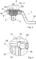
- a locking member 20 and an actuator 21 comprehensive fixing device 25 is arranged on the mounting flange 16 .
- the actuator 21 is pin-shaped and is arranged in the mounting flange 16 tangentially to the axis of rotation 7 of the output shaft slidably.
- a displacement of the actuating element 21 can be generated by pressure on a radially enlarged head 37 of the actuating element 21 forming the pin 31.
- the actuator 21 is preferably formed in two parts, and then consists of the guided in a bore 36 of the mounting flange 16 pin 31 and the end of the pin forming, widened head 37.
- the head 37 is outside the bore 36, and in this way by hand.
- FIG. 3 and FIG. 4 shows that around the gear housing 4 around an outer spline 8 is arranged, the mutually parallel and each having the same circumferential spacing teeth 9 to the rear, ie in the direction of the drive part 3, only up to a surrounding the transmission housing 4 over its entire circumference Groove 10 extend.
- the groove base 11 of the groove 10 is located on a diameter D1 which is smaller than the diameter D2 described by the tips 13 of the teeth 9.
- the spline 8 is a series of teeth 9 arranged circumferentially around the transmission housing 4, all of which extend in the longitudinal direction.
- the individual teeth 9 are each formed by tooth flanks 23 and a tooth tip 13.
- the teeth 9 are separated by gaps and tooth roots 24 and have equal distances from each other.
- an internal spline is arranged on the annular mounting flange 16. This cooperates with the spline 8 on the transmission housing 4 such that the support arm 1 is rotationally fixed to the transmission housing 4. Specifically, this means that the teeth of the internal spline of the mounting flange 16 in the intervene between the individual tooth flanks 23 of the teeth 9 of the spline 8 of the gear housing 4 interdental spaces, and vice versa.
- the fixing device 25 can assume a blocking or a release position, wherein the support arm 1 is fixed in the blocking position in the longitudinal direction of the rotation axis or output shaft 7 to the transmission housing 4.
- the locking element 20, preferably a ball, in the blocking position of the fixing device 25 extends partially into the groove 10 ( Fig. 4 ). Partially remains the locking member 20, even in the locked position, in the mounting flange sixteenth
- the actuating element 21 In order to move from the blocking position into a release position of the fixing device 25, which allows the support arm 1 or fastening flange 16 to be pulled down from the transmission housing 4, the actuating element 21 has to be actuated by the operator.
- the actuator 21 is within the mounting flange 16 tangentially to the axis of rotation 7 of the rotary screw displaceably arranged pin 31 which is biased against a compression spring 30.
- the pin 31 has a link or a recess 35 into which the ball 20 projects with a part of its spherical volume.
- the actuator 21 is composed of the guided in the bore 36 of the mounting flange 16 pin 31 and the end of the pen forming, enlarged head 37 together.
- Pin 31 and head 37 are preferably in two parts, but may also be formed in one piece or in one piece.
- the head 37 is extended in comparison to the pin 31, for example radially expanded.
- the radially expanded portion of the head 37 is located outside the bore 36 of the mounting flange 16 and can thus be operated by the operator.
- the head 37 can receive the pin 31 in a bore 41 of the head 37, for example by a screw connection.
- pin 31 are connected to head 37 in operative connection.
- the pin 31 is pressed against the force of a spring 30 in the bore 36.
- a compression spring 30 is supported, which is supported on its other side to a stopper 40 which closes the bore 36 outwardly.
- the plug 40 may be compressed in the bore 36 or fastened by screwing. When screwing the plug 40 has a corresponding external thread and the bore 36 to a corresponding internal thread.
- additional openings may be provided on the mounting flange 16, which allow access from the outside to the bore 36.
- a corresponding opening 45 can be arranged laterally of the pin 31 in the fastening flange 16.
- This bore 36 can be closed with a stopper 46. If the plugs 40, 46 are removed, the components arranged inside the bore 36 or in the fastening flange 16, in particular the pressure spring 30, the actuating element 21 and the locking element 20 can be removed from the bore 36 or the flange 16 and replaced. This is advantageous in particular for maintenance purposes.
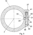
- Fig. 5 is the mounting flange 16 together with fixing device 25 in the sectional plane VV gem.
- Fig. 3 shown. The viewing direction to be considered is indicated by corresponding arrows in Fig. 3 characterized.
- the fixing device 25 is in its blocking position. If the actuating element 21 is actuated, the head 37 together with the pin 31 shifts in the direction of the compression spring 30. The compression spring 30 is compressed or compressed and the locking element 20 or the ball can escape into the slot or recess 35 on the pin 31, and Although radially relative to the axis of rotation 7. As a result, the locking member 20 is in its release position. In this, the locking element 20 no longer extends into the groove 10 in contrast to the blocking position, and the support arm 1 can be withdrawn in the longitudinal direction of the output shaft 7 of the screwdriver 2.
- the locking element 20 and the actuating element 21 may be made of the same material or of different materials.
- the locking element 20 and the actuating element 21 may be made of metal.
Landscapes
- Engineering & Computer Science (AREA)
- Mechanical Engineering (AREA)
- Details Of Spanners, Wrenches, And Screw Drivers And Accessories (AREA)
- Snaps, Bayonet Connections, Set Pins, And Snap Rings (AREA)
- Gear Transmission (AREA)
- General Details Of Gearings (AREA)
Abstract
Description
- Die Erfindung betrifft eine Anordnung aus einem Reaktionsmomente ableitenden Stützarm und einem Drehschrauber, welcher ein Antriebsteil und ein Getriebegehäuse mit einer nach vorne aus dem Getriebegehäuse herausgeführten Ausgangswelle aufweist und um das Getriebegehäuse herum mit einer äußeren Keilverzahnung versehen ist, deren Zähne sich nach hinten bis an eine das Getriebegehäuse über dessen Umfang umgebende Nut erstrecken, deren Nutgrund auf einem Durchmesser liegt, der kleiner ist als der von den Spitzen der Zähne beschriebene Durchmesser, wobei der Stützarm einen Befestigungsabschnitt mit einem ringförmigen Befestigungsflansch und einer inneren Keilverzahnung, sowie einen seitlich versetzt zu der Ausgangswelle angeordneten, gegen ein externes Widerlager anlegbaren Stützfuß aufweist, wobei die Keilverzahnung des Befestigungsflansches mit der Keilverzahnung des Getriebegehäuses derart zusammenwirkt, dass der Stützarm drehfest zu dem Getriebegehäuse ist, wobei an dem Befestigungsflansch ein Arretierelement angeordnet ist, welches eine Sperr- oder eine Lösestellung einnehmen kann, und wobei der Stützarm in der Sperrstellung in Längsrichtung an dem Getriebegehäuse festgelegt ist.
- Während eines Schraubvorgangs werden Drehschrauber in der Regel von einem Bediener über einen Handgriff gehalten. Das beim Schraubprozess entstehende, oft erhebliche Reaktionsmoment kann über einen drehfest an dem Drehschrauber befestigten Stützarm abgeleitet werden. Dazu muss der Stützarm an einem vorhandenen festen Bauteil, etwa einer benachbarten Verschraubung, anliegen bzw. sich daran abstützen. Die benachbarte Verschraubung dient dann als Widerlager. Dadurch wird eine Übertragung von Reaktionsmomenten auf den Bediener des Drehschraubers, z.B. über den Handgriff, vermieden. Oft sind die auftretenden Reaktionsmomente vorab schwer einzuschätzen und können zu einem unkalkulierbaren Risiko für den Bediener führen, und etwa ein Rückschlagen des Drehschraubers hervorrufen. Somit wird die Betriebssicherheit des Drehschraubers durch eine entsprechende Stützarm-Anordnung an dem Drehschrauber erhöht. Ferner ergibt sich daraus auch eine komfortablere Nutzung des Drehschraubers.
- Zur Befestigung eines solchen Stützarmes an einem Drehschrauber ist aus der
DE 10 2009 005 997 A1 bekannt, dass der Stützarm einen ringförmigen Befestigungsflansch mit einer Innenverzahnung aufweist und auf ein die Ausgangswelle umgebendes Getriebegehäuse mit einer entsprechenden Außenverzahnung aufschiebbar ist. Dadurch ist der Stützarm drehfest gegenüber dem Getriebegehäuse. Zur Fixierung des Stützarmes auch in Längsrichtung der Ausgangswelle ist z. B. in einem Zahn oder Zahngrund der Innenverzahnung eine radial verschieblich gelagerte Kugel angeordnet. Ein federvorgespannter Betätigungsstift nimmt die Kugel zumindest teilweise in einer Kulisse auf. Im betätigten Zustand des Betätigungsstifts verklemmt die Kugel gegen die Zahnflanken oder Zahnspitzen der Außenverzahnung, und verklemmt so das Getriebegehäuse axial gegenüber dem Stützarm. - Nachteilig dabei kann sein, dass die Befestigung in der Längsrichtung allein auf Klemm- bzw. Reibkräften beruht. Dadurch besteht die Gefahr, dass bei entsprechender Druck- oder Zugbelastung des Arms gegenüber dem Drehschrauber die Befestigungsstellung gelöst wird, und der Stützarm samt Befestigungsflansch vom Getriebegehäuse des Drehschraubers abrutscht. Auch kommt es bei einer solchen auf Klemm- und Reibkräften basierenden Befestigung zu einer erhöhten Materialabnutzung durch Materialabrieb.
- Der Erfindung liegt die Aufgabe zugrunde, eine Anordnung aus einem Reaktionsmomente ableitenden Stützarm und einem Drehschrauber bereitzustellen, die eine zuverlässige, sichere und abnutzungsarme Befestigung des Stützarmes an dem Drehschrauber ermöglicht.
- Zur Lösung dieser Aufgabe wird eine Anordnung aus einem Reaktionsmomente ableitenden Stützarm und einem Drehschrauber mit den in Patentanspruch 1 angegebenen Merkmalen vorgeschlagen.
- Die erfindungsgemäße Anordnung besteht zunächst aus einem Reaktionsmomente ableitenden Stützarm und einem Drehschrauber. Der Drehschrauber weist ein Antriebsteil und ein Getriebegehäuse mit einer nach vorne aus dem Getriebegehäuse herausgeführten Ausgangswelle auf. Ferner kann der Drehschrauber weitere Komponenten aufweisen. Zu diesen zählen ein Handgriff, im Fall eines elektrisch angetriebenen Drehschraubers ein Akkumodul, ferner Bedienelemente sowie visuelle und/oder akustische Anzeigen. Die Erfindung ist aber auch an einem pneumatisch angetriebenen Drehschrauber realisierbar.
- Um das Getriebegehäuse herum ist eine äußere Keilverzahnung angeordnet, deren Zähne sich nach hinten bis an eine das Getriebegehäuse über dessen gesamten Umfang umgebende Nut erstrecken, deren Nutgrund auf einem Durchmesser liegt, der kleiner ist als der Durchmesser, den die Zahnspitzen der äußeren Keilverzahnung beschreiben.
- Der Stützarm weist einen Befestigungsabschnitt mit einem ringförmigen Befestigungsflansch und einer inneren Keilverzahnung, sowie einen gegen ein externes Widerlager anlegbaren Stützabschnitt mit einem Stützfuß auf, der seitlich versetzt zu der Ausgangswelle angeordnet ist. Die innere Keilverzahnung an dem Befestigungsflansch wirkt mit der äußeren Keilverzahnung an dem Getriebegehäuse derart zusammen, dass der Stützarm drehfest zu dem Getriebegehäuse ist.
- An dem Befestigungsflansch ist ein Arretierelement angeordnet, welches eine Sperr- oder eine Lösestellung einnehmen kann. Der Stützarm ist in der Sperrstellung in Längsrichtung an dem Getriebegehäuse festgelegt. In der Sperrstellung erstreckt sich das Arretierelement zumindest teilweise in die Nut hinein und verriegelt so den Stützarm in Längsrichtung an dem Getriebegehäuse, und zwar in einer definierten Längsposition.
- Mit der Erfindung wird eine bei Drehschraubern oft ohnehin an dem Getriebegehäuse vorhandene Nut genutzt, um den Stützarm in einer eindeutigen Längsposition zu arretieren. Die Befestigung beruht somit im Gegensatz zur Lösung aus der
DE 10 2009 005 997 A1 nicht auf einem nur kraftschlüssigen Verklemmen und zeigt auch bei dauerhaftem Einsatz eine geringe Abnutzung. Vorstellbar ist es auch, mehrere solcher Fixiervorrichtungen umfänglich des Befestigungsflansches anzuordnen, beispielsweise um die formschlüssige Arretierung nochmals zu verbessern. - Gemäß einer bevorzugten Ausgestaltung der Erfindung ist das Arretierelement Bestandteil einer außerdem ein Betätigungselement umfassenden Fixiervorrichtung, wobei das Betätigungselement ein innerhalb des Befestigungsflansches tangential verschiebbar angeordneter, gegen eine Druckfeder vorgespannter Stift, der eine Kulisse oder Ausnehmung zur teilweisen Aufnahme des Arretierelements in der Lösestellung aufweist. Durch die tangentiale Anordnung des Betätigungselements bzw. Stifts wird die Zugänglichkeit des Stifts bei Betätigung durch den Bediener erleichtert. Aus dem Stand der Technik ist eine axiale Anordnung eines solchen Stifts bekannt. Dies kann je nach Schraubsituation zu einer schwierigeren Zugänglichkeit des Stifts führen. Die Betätigung des Stifts kann auch in einer akuten Schraubsituation notwendig werden, beispielsweise zur Nachjustierung des Stützarmes. Insbesondere bei engen Platzverhältnissen ist es dann vorteilhaft, den Stift von der Seite betätigen zu können.
- Nach einer weiteren Ausgestaltung der Erfindung ist vorteilhaft, dass sich das Betätigungselement aus dem in einer Bohrung des Befestigungsflansches geführten Stift sowie einem das Stiftende bildenden, erweiterten Kopf zusammensetzt. Durch die Zweiteiligkeit des Betätigungselements wird einerseits eine saubere Führung des Betätigungselements in der Bohrung gewährleistet, andererseits aber auch eine leichte Betätigbarkeit von außen. Der Stift und der Kopf können einstückig sein, oder beispielsweise miteinander verschraubt sein. So kann der Kopf eine Bohrung mit einem Innengewinde aufweisen, in welches der Stift mit einem Außengewinde eingeschraubt wird.
- Vorteilhaft ist es zudem, wenn sich die Druckfeder einerseits an einem dem Kopf abgewandten Ende des Stifts und andererseits an einem die Bohrung nach außen abschließenden Stopfen abstützt. Die Abstützung der Druckfeder an einem Ende des Stifts ist für die erfindungsgemäße Anordnung zwingend notwendig. Nur so kann das Arretierelement in der Sperrstellung zumindest teilweise in die Nut eingreifen. Die Federkraft hält den Stift also selbstständig in der für die Sperrstellung der Fixiervorrichtung notwendigen Position. Die weitere Abstützung der Druckfeder an einem die Bohrung nach außen abschließenden Stopfen ist dahingehend vorteilhaft, dass bei Entfernung des Stopfens, sowohl die Druckfeder, als auch der Stift oder das Arretierelement in einfacher Weise aus der Bohrung entfernt und zum Beispiel ausgetauscht werden kann. Zusätzlich können weitere ausgehend von der Bohrung nach außen führende Kanäle oder Bohrungen vorgesehen sein, die ebenfalls mit Stopfen verschließbar sind.
- Gemäß einer weiteren Ausgestaltung der Erfindung ist der Stopfen in der Bohrung verpresst oder durch Verschraubung befestigt. Dies ermöglicht ein einfaches und schnelles Entfernen des Stopfens bei Bedarf, beispielsweise wenn der Stift, das Arretierelement oder die Druckfeder zu Wartungszwecken aus der Bohrung entfernt und/oder ausgetauscht werden müssen. Selbstverständlich können auch weitere in dem Befestigungsflansch angeordnete Bohrungen, die in Verbindung zu der Führungsbohrung des Stifts stehen, mit Stopfen derart verschlossen werden, dass diese in der jeweiligen Bohrung verpresst oder verschraubt sind.
- Weitere Einzelheiten und Vorteile der Erfindung ergeben sich aus der nachfolgenden Beschreibung der zugehörigen Zeichnungen, in denen ein Ausführungsbeispiel der erfindungsgemäßen Anordnung dargestellt ist. In den Zeichnungen zeigen:
- Fig. 1
- eine schematische Darstellung einer Anordnung aus einem Drehschrauber und einem daran befestigten Stützarm;
- Fig. 2
- eine schematische Darstellung des Getriebegehäuses des Drehschraubers samt daran befestigtem Sützarm;
- Fig. 3
- eine vergrößerte Seitenansichtansicht des Befestigungsbereiches zwischen Stützarm und Getriebegehäuse;
- Fig. 4
- eine vergrößerte Detailansicht der Einzelheit IV aus
Fig. 3 ; - Fig. 5
- ein Querschnitt durch den Befestigungsflansch gemäß Blickrichtung V-V in
Fig. 3 . - Bestandteile der erfindungsgemäßen Anordnung sind ein Drehschrauber 2 und ein die Verschraubungsmomente aufnehmender Stützarm 1. Die
Fig. 1 zeigt einen entsprechenden Drehschrauber 2 mit einem daran befestigten Stützarm 1. Der Drehschrauber 2 setzt sich zunächst aus einem Antriebsteil 3 und einem Getriebegehäuse 4 zusammen. Beide Komponenten können auch z.B. über ein Drehgelenk miteinander verbunden sein. - In dem Antriebsteil 3 kann eine motorische Einrichtung zum Betrieb des Drehschraubers 2 vorgesehen sein. Auch eine pneumatische oder elektrische Betriebsweise kann prinzipiell in Betracht kommen. Zudem kann in Nähe zu dem Antriebsteil 3 ein Handgriff 5 und ein Akku 6 bzw. eine Batterie vorgesehen sein. Ein solcher Akku 6 kann austauschbar an dem Drehschrauber 2 befestigt sein. Der Akku 6 stellt die benötigte elektrische Energie zum Betrieb des Drehschraubers 2 zur Verfügung. Selbstverständlich kann ein solcher Drehschrauber 2 auch über eine entsprechende Kabelverbindung mit elektrischer Energie versorgt werden. Innerhalb des Getriebegehäuses 4 können für den Betrieb des Drehschraubers 2 notwendige Getriebebestandteile, z.B. ein Drehmomentwandler und ein Getriebe angeordnet sein.
- Ein wesentlicher Bestandteil ist ferner eine nach vorne aus dem Getriebegehäuse 4 herausführende Ausgangswelle 7. Diese schließt an ihrem vorderen Ende mit einem Mehrkant 12 zur austauschbaren Befestigung eines Werkzeugs ab.
- Zum Betrieb des Drehschraubers 2 hält der Bediener den Drehschrauber 2 über den Handgriff 5 in seiner Hand. Die Aktivierung des Drehschraubers 2 bzw. die Steuerung des Schraubvorgangs findet in erster Linie durch Betätigung eines entsprechenden Schalters 14 statt. Über einen zusätzlichen Schalter 17 kann die Drehrichtung der Ausgangswelle 7 umgeschaltet werden.
- Wie ebenfalls aus
Fig. 1 ersichtlich ist, kann an dem Drehschrauber 2 bzw. am vorderen Ende des Getriebegehäuses 4 der Stützarm 1 befestigt werden. Im Wesentlichen ist der Stützarm 1 seitlich versetzt zu der Drehachse der Ausgangswelle 7 angeordnet. Der Stützarm 1 weist einen als ringförmiger Befestigungsflansch 16 ausgebildeten Befestigungsabschnitt 15 sowie einen Stützabschnitt 19 mit einem Stützfuß 18 auf, der gegen ein externes Widerlager anlegbar ist. Das externe Widerlager kann durch vorhandene Maschinen- oder Bauteile gebildet werden, beispielsweise die Mutter einer benachbarten Verschraubung. - Wie insbesondere in den
Figuren 2 und3 zu erkennen, ist an dem Befestigungsflansch 16 eine ein Arretierelement 20 und ein Betätigungselement 21 umfassende Fixiervorrichtung 25 angeordnet. Das Betätigungselement 21 ist stiftförmig und ist in dem Befestigungsflansch 16 tangential zur Drehachse 7 der Ausgangswelle verschiebbar angeordnet. Eine Verschiebung des Betätigungselements 21 kann durch Druck auf einen radial erweiterten Kopf 37 des das Betätigungselement 21 bildenden Stifts 31 erzeugt werden. - Das Betätigungselement 21 ist vorzugsweise zweiteilig ausgebildet, und besteht dann aus dem in einer Bohrung 36 des Befestigungsflansches 16 geführten Stift 31 sowie dem das Stiftende bildenden, erweiterten Kopf 37. Der Kopf 37 ist außerhalb der Bohrung 36, und auf diese Weise von Hand greifbar.
- Aus
Figur 3 und Figur 4 geht hervor, dass um das Getriebegehäuse 4 herum eine äußere Keilverzahnung 8 angeordnet ist, deren zueinander parallele und jeweils gleiche Umfangsabstände aufweisenden Zähne 9 sich nach hinten, also in Richtung zu dem Antriebsteil 3, nur bis an eine das Getriebegehäuse 4 über dessen gesamten Umfang umgebende Nut 10 erstrecken. Der Nutgrund 11 der Nut 10 liegt auf einem Durchmesser D1, der kleiner ist als der von den Spitzen 13 der Zähne 9 beschriebene Durchmesser D2. - Die Keilverzahnung 8 ist eine umfänglich um das Getriebegehäuse 4 herum angeordnete Folge von Zähnen 9, die sich alle in Längsrichtung erstrecken. Die einzelnen Zähne 9 werden jeweils von Zahnflanken 23 und einer Zahnspitze 13 gebildet. Die Zähne 9 sind durch Zwischenräume und Zahngründe 24 getrennt und weisen gleiche Abstände zueinander auf.
- Korrespondierend ist eine innere Keilverzahnung an dem ringförmigen Befestigungsflansch 16 angeordnet. Diese wirkt mit der Keilverzahnung 8 an dem Getriebegehäuse 4 derart zusammen, dass der Stützarm 1 drehfest zu dem Getriebegehäuse 4 ist. Konkret bedeutet dies, dass die Zähne der inneren Keilverzahnung des Befestigungsflansches 16 in die zwischen den einzelnen Zahnflanken 23 der Zähne 9 der Keilverzahnung 8 des Getriebegehäuses 4 befindlichen Zahnzwischenräume eingreifen, und umgekehrt.
- Die Fixiervorrichtung 25 kann eine Sperr- oder eine Lösestellung einnehmen, wobei der Stützarm 1 in der Sperrstellung in Längsrichtung der Drehachse bzw. Ausgangswelle 7 an dem Getriebegehäuse 4 festgelegt ist. Dazu erstreckt sich das Arretierelement 20, vorzugsweise eine Kugel, in der Sperrstellung der Fixiervorrichtung 25 teilweise in die Nut 10 hinein (
Fig. 4 ). Teilweise verbleibt das Arretierelement 20, auch in der Sperrstellung, in dem Befestigungsflansch 16. - Um von der Sperrstellung in eine Lösestellung der Fixiervorrichtung 25 zu gelangen, welche ein Herunterziehen des Stützarmes 1 bzw. Befestigungsflansches 16 von dem Getriebegehäuse 4 ermöglicht, muss das Betätigungselement 21 durch den Bediener betätigt werden.
- Wie insbesondere in
Fig. 5 dargestellt, ist das Betätigungselement 21 der innerhalb des Befestigungsflansches 16 tangential zur Drehachse 7 des Drehschraubers verschiebbar angeordnete Stift 31, der gegen eine Druckfeder 30 vorgespannt ist. Der Stift 31 weist eine Kulisse oder eine Ausnehmung 35 auf, in die die Kugel 20 mit einem Teil ihres Kugelvolumens ragt. - Vorzugsweise setzt sich das Betätigungselement 21 aus dem in der Bohrung 36 des Befestigungsflansches 16 geführten Stift 31 sowie dem das Stiftende bildenden, erweiterten Kopf 37 zusammen. Stift 31 und Kopf 37 sind vorzugsweise zweiteilig, können aber auch einteilig bzw. einstückig ausgebildet sein. Der Kopf 37 ist im Vergleich zum Stift 31 erweitert, beispielsweise radial erweitert. Der radial erweiterte Teil des Kopfes 37 liegt außerhalb der Bohrung 36 des Befestigungsflansches 16 und kann so von dem Bediener betätigt werden.
- Wie
Figur 5 zeigt, kann der Kopf 37 in einer Bohrung 41 des Kopfes 37 den Stift 31 aufnehmen, zum Beispiel durch eine Schraubverbindung. Somit stehen Stift 31 mit Kopf 37 in Wirkverbindung. Bei Betätigung des Betätigungselements 21, also des Kopfes 37, wird der Stift 31 entgegen der Kraft einer Feder 30 in die Bohrung 36 hineingedrückt. An dem dem Kopf 37 des Stifts 31 abgewandten Ende des Stifts 31 stützt sich eine Druckfeder 30 ab, die zu ihrer anderen Seite an einem die Bohrung 36 nach außen verschließenden Stopfen 40 abgestützt ist. Der Stopfen 40 kann in der Bohrung 36 verpresst oder durch Verschraubung befestigt sein. Bei Verschraubung weist der Stopfen 40 ein entsprechendes Außengewinde und die Bohrung 36 ein dazu korrespondierendes Innengewinde auf. - Es können zusätzlich auch weitere Öffnungen an dem Befestigungsflansch 16 vorgesehen sein, die einen Zugang von außen zur Bohrung 36 ermöglichen. So kann beispielsweise eine entsprechende Öffnung 45 seitlich des Stifts 31 in dem Befestigungsflansch 16 angeordnet sein. Auch diese Bohrung 36 kann mit einem Stopfen 46 verschlossen werden. Werden die Stopfen 40, 46 entfernt, so können die innerhalb der Bohrung 36 bzw. im Befestigungsflansch 16 angeordneten Bauteile, insbesondere die Druckfeder 30, das Betätigungselement 21 und das Arretierelement 20 aus der Bohrung 36 bzw. dem Flansch 16 entfernt und ausgetauscht werden. Insbesondere für Wartungszwecke ist dies vorteilhaft.
- In
Fig. 5 ist der Befestigungsflansch 16 samt Fixiervorrichtung 25 in der Schnittebene V-V gem.Fig. 3 dargestellt. Die zu berücksichtigende Blickrichtung ist durch entsprechende Pfeile inFig. 3 gekennzeichnet. - Bei
Fig. 5 befindet sich die Fixiervorrichtung 25 in ihrer Sperrstellung. Wird das Betätigungselement 21 betätigt, verschiebt sich der Kopf 37 samt Stift 31 in Richtung zu der Druckfeder 30. Die Druckfeder 30 wird komprimiert bzw. gestaucht und das Arretierelement 20 bzw. die Kugel kann in die Kulisse oder Ausnehmung 35 am Stift 31 ausweichen, und zwar radial in Bezug auf die Drehachse 7. Dadurch gelangt das Arretierelement 20 in seine Lösestellung. In dieser erstreckt sich das Arretierelement 20 im Gegensatz zur Sperrstellung nicht mehr in die Nut 10 hinein, und der Stützarm 1 kann in Längsrichtung der Ausgangswelle 7 von dem Drehschrauber 2 abgezogen werden. - In der Sperrstellung ist diese Bewegung nicht möglich, da das Arretierelement 20 bzw. die Kugel durch ihr teilweises Hineinragen in die Nut 10 die hinteren Zahnenden übergreift und den Stützarm 1 gegenüber dem Getriebegehäuse 4 bzw. dem Drehschrauber 2 in einer eindeutigen Längsposition arretiert, und zwar mittels Formschluss.
- Das Arretierelement 20 und das Betätigungselement 21 können aus demselben Material oder aus unterschiedlichen Materialien gefertigt sein. Insbesondere können das Arretierelement 20 und das Betätigungselement 21 aus Metall gefertigt sein.
-
- 1
- Stützarm
- 2
- Drehschrauber
- 3
- Antriebsteil
- 4
- Getriebegehäuse
- 5
- Handgriff
- 6
- Akku
- 7
- Ausgangswelle, Drehachse
- 8
- äußere Keilverzahnung
- 9
- Zahn
- 10
- Nut
- 11
- Nutgrund
- 12
- Mehrkant
- 13
- Spitze
- 14
- Schalter
- 15
- Befestigungsabschnitt
- 16
- Befestigungsflansch
- 17
- Schalter
- 18
- Stützfuß
- 19
- Stützabschnitt
- 20
- Arretierelement, Kugel
- 21
- Betätigungselement
- 23
- Zahnflanke
- 24
- Zahngrund
- 25
- Fixiervorrichtung
- 30
- Druckfeder
- 31
- Stift
- 35
- Ausnehmung
- 36
- Bohrung
- 37
- Kopf
- 40
- Stopfen
- 41
- Bohrung
- 45
- Öffnung
- 46
- Stopfen
- D1
- Durchmesser
- D2
- Durchmesser
Claims (5)
- Anordnung aus einem Reaktionsmomente ableitenden Stützarm (1) und einem Drehschrauber (2), welcher ein Antriebsteil (3) und ein Getriebegehäuse (4) mit einer nach vorne aus dem Getriebegehäuse (4) herausgeführten Ausgangswelle (7) aufweist und um das Getriebegehäuse (4) herum mit einer äußeren Keilverzahnung (8) versehen ist, deren Zähne (9) sich nach hinten bis an eine das Getriebegehäuse (4) über dessen Umfang umgebende Nut (10) erstrecken, deren Nutgrund (11) auf einem Durchmesser (D1) liegt, der kleiner ist als der von den Spitzen (13) der Zähne (9) beschriebene Durchmesser (D2), wobei der Stützarm (1) einen Befestigungsabschnitt (15) mit einem ringförmigen Befestigungsflansch (16) und einer inneren Keilverzahnung, sowie einen seitlich versetzt zu der Ausgangswelle (7) angeordneten, gegen ein externes Widerlager anlegbaren Stützfuß (18) aufweist, wobei die Keilverzahnung des Befestigungsflansches (16) mit der Keilverzahnung (8) des Getriebegehäuses (4) derart zusammenwirkt, dass der Stützarm (1) drehfest zu dem Getriebegehäuse (4) ist, wobei an dem Befestigungsflansch (16) ein Arretierelement (20) angeordnet ist, welches eine Sperr- oder eine Lösestellung einnehmen kann, und wobei der Stützarm (1) in der Sperrstellung in Längsrichtung an dem Getriebegehäuse (4) festgelegt ist, dadurch gekennzeichnet, dass sich das Arretierelement (20) in der Sperrstellung teilweise oder ganz in die Nut (10) hinein erstreckt und so den Stützarm (1) in Längsrichtung an dem Getriebegehäuse (4) verriegelt.
- Anordnung nach Anspruch 1, dadurch gekennzeichnet, dass das Arretierelement (20) Bestandteil einer außerdem ein Betätigungselement (21) umfassenden Fixiervorrichtung (25) ist, wobei das Betätigungselement (21) ein innerhalb des Befestigungsflansches (16) tangential verschiebbar angeordneter, gegen eine Druckfeder (30) vorgespannter Stift (31) ist, der eine Kulisse oder Ausnehmung (35) zur teilweisen Aufnahme des Arretierelements (20) in der Lösestellung aufweist.
- Anordnung nach einem der Ansprüche, dadurch gekennzeichnet, dass sich das Betätigungselement (21) aus dem in einer Bohrung (36) des Befestigungsflansches (16) geführten Stift (31) sowie einem das Stiftende bildenden, erweiterten Kopf (37) zusammensetzt.
- Anordnung nach Anspruch 3, dadurch gekennzeichnet, dass sich die Druckfeder (30) einerseits an einem dem Kopf (37) abgewandten Ende des Stifts (31) und andererseits an einem die Bohrung (36) nach außen abschließenden Stopfen (40) abstützt.
- Anordnung nach Anspruch 4, dadurch gekennzeichnet, dass der Stopfen (40) in der Bohrung (36) verpresst oder durch Verschraubung befestigt ist.
Applications Claiming Priority (1)
| Application Number | Priority Date | Filing Date | Title |
|---|---|---|---|
| DE102017105025.6A DE102017105025A1 (de) | 2017-03-09 | 2017-03-09 | Anordnung aus einem Reaktionsmomente ableitenden Stützarm und einem Drehschrauber |
Publications (2)
| Publication Number | Publication Date |
|---|---|
| EP3372343A1 true EP3372343A1 (de) | 2018-09-12 |
| EP3372343B1 EP3372343B1 (de) | 2022-05-04 |
Family
ID=61526703
Family Applications (1)
| Application Number | Title | Priority Date | Filing Date |
|---|---|---|---|
| EP18159366.6A Active EP3372343B1 (de) | 2017-03-09 | 2018-03-01 | Anordnung aus einem reaktionsmomente ableitenden stützarm und einem drehschrauber |
Country Status (8)
| Country | Link |
|---|---|
| US (1) | US10888980B2 (de) |
| EP (1) | EP3372343B1 (de) |
| JP (1) | JP7033959B2 (de) |
| KR (1) | KR102550874B1 (de) |
| CN (1) | CN108568772B (de) |
| DE (1) | DE102017105025A1 (de) |
| DK (1) | DK3372343T3 (de) |
| ES (1) | ES2913925T3 (de) |
Cited By (2)
| Publication number | Priority date | Publication date | Assignee | Title |
|---|---|---|---|---|
| CN110293503A (zh) * | 2019-07-03 | 2019-10-01 | 刘安胜 | 具有调节结构的螺栓拧动装置 |
| FR3105414A1 (fr) | 2019-12-24 | 2021-06-25 | Etablissements Georges Renault | Procédé de détermination du couple de serrage minimal d’un dispositif de vissage/dévissage, et dispositif correspondant |
Families Citing this family (1)
| Publication number | Priority date | Publication date | Assignee | Title |
|---|---|---|---|---|
| US20250162123A1 (en) * | 2023-11-17 | 2025-05-22 | Milwaukee Electric Tool Corporation | Reaction arm power tool with clutch mechanism |
Citations (5)
| Publication number | Priority date | Publication date | Assignee | Title |
|---|---|---|---|---|
| US4794825A (en) * | 1986-11-03 | 1989-01-03 | Atlantic-Caribbean Products, Inc. | Hydraulic power wrench |
| EP1329293A2 (de) * | 2002-01-22 | 2003-07-23 | John K. Junkers | Einstellbarer Reaktionsarm für ein angetriebenes Drehmomentwerkzeug und hiermit versehenes angetriebenes Drehmomentwerkzeug |
| DE20301759U1 (de) * | 2003-02-05 | 2004-06-17 | Wagner, Paul-Heinz | Kraftschrauber |
| EP2210709A2 (de) * | 2009-01-23 | 2010-07-28 | Lösomat Schraubtechnik Neef GmbH | Stützfuß für Kraftschrauber |
| DE202013004157U1 (de) * | 2013-05-06 | 2013-06-24 | LÖSOMAT-Schraubtechnik Neef GmbH | Vorrichtung zur Axialsicherung verzahnter Elemente |
Family Cites Families (11)
| Publication number | Priority date | Publication date | Assignee | Title |
|---|---|---|---|---|
| US4155278A (en) * | 1977-09-06 | 1979-05-22 | Cooper Industries, Inc. | Swivel head reaction bar nut runner |
| US7225707B2 (en) * | 2005-09-14 | 2007-06-05 | Brian Knopp | Torque wrench with quick-release gear set |
| CN2843767Y (zh) * | 2005-10-24 | 2006-12-06 | 山东同力达机电装备有限公司 | 电动定扭矩扳手自动定位反力机构 |
| US7451672B2 (en) * | 2006-01-11 | 2008-11-18 | Jetyd Corp. | Link attachment to torque wrench |
| SE531646C2 (sv) * | 2007-10-17 | 2009-06-16 | Atlas Copco Tools Ab | Skruvdragare med organ för övervakning av en reaktionsarm |
| US8042434B2 (en) * | 2008-01-24 | 2011-10-25 | Junkers John K | Safety torque intensifying tool |
| US7832310B2 (en) * | 2008-07-18 | 2010-11-16 | Junkers John K | Torque power tool |
| KR101165343B1 (ko) * | 2010-04-19 | 2012-07-18 | (주)세원피엠텍 | 왼나사 및 오른나사 겸용 토크 제어용 렌치 |
| SE535307C2 (sv) * | 2010-07-14 | 2012-06-26 | Atlas Copco Tools Ab | Låsmutter för en reaktionsarm |
| DE102015111570A1 (de) * | 2015-07-16 | 2017-01-19 | Jörg Hohmann | Drehschrauber |
| CN205415470U (zh) * | 2016-03-21 | 2016-08-03 | 上海虎啸电动工具有限公司 | 一种电动扭矩扳手 |
-
2017
- 2017-03-09 DE DE102017105025.6A patent/DE102017105025A1/de not_active Withdrawn
-
2018
- 2018-03-01 ES ES18159366T patent/ES2913925T3/es active Active
- 2018-03-01 DK DK18159366.6T patent/DK3372343T3/da active
- 2018-03-01 EP EP18159366.6A patent/EP3372343B1/de active Active
- 2018-03-03 US US15/911,073 patent/US10888980B2/en active Active
- 2018-03-07 JP JP2018040610A patent/JP7033959B2/ja active Active
- 2018-03-08 KR KR1020180027515A patent/KR102550874B1/ko active Active
- 2018-03-09 CN CN201810192394.3A patent/CN108568772B/zh active Active
Patent Citations (5)
| Publication number | Priority date | Publication date | Assignee | Title |
|---|---|---|---|---|
| US4794825A (en) * | 1986-11-03 | 1989-01-03 | Atlantic-Caribbean Products, Inc. | Hydraulic power wrench |
| EP1329293A2 (de) * | 2002-01-22 | 2003-07-23 | John K. Junkers | Einstellbarer Reaktionsarm für ein angetriebenes Drehmomentwerkzeug und hiermit versehenes angetriebenes Drehmomentwerkzeug |
| DE20301759U1 (de) * | 2003-02-05 | 2004-06-17 | Wagner, Paul-Heinz | Kraftschrauber |
| EP2210709A2 (de) * | 2009-01-23 | 2010-07-28 | Lösomat Schraubtechnik Neef GmbH | Stützfuß für Kraftschrauber |
| DE202013004157U1 (de) * | 2013-05-06 | 2013-06-24 | LÖSOMAT-Schraubtechnik Neef GmbH | Vorrichtung zur Axialsicherung verzahnter Elemente |
Cited By (2)
| Publication number | Priority date | Publication date | Assignee | Title |
|---|---|---|---|---|
| CN110293503A (zh) * | 2019-07-03 | 2019-10-01 | 刘安胜 | 具有调节结构的螺栓拧动装置 |
| FR3105414A1 (fr) | 2019-12-24 | 2021-06-25 | Etablissements Georges Renault | Procédé de détermination du couple de serrage minimal d’un dispositif de vissage/dévissage, et dispositif correspondant |
Also Published As
| Publication number | Publication date |
|---|---|
| KR20180103740A (ko) | 2018-09-19 |
| JP7033959B2 (ja) | 2022-03-11 |
| US10888980B2 (en) | 2021-01-12 |
| KR102550874B1 (ko) | 2023-07-03 |
| DE102017105025A1 (de) | 2018-09-13 |
| CN108568772A (zh) | 2018-09-25 |
| CN108568772B (zh) | 2021-07-30 |
| DK3372343T3 (da) | 2022-06-20 |
| ES2913925T3 (es) | 2022-06-06 |
| EP3372343B1 (de) | 2022-05-04 |
| JP2018149672A (ja) | 2018-09-27 |
| US20180257204A1 (en) | 2018-09-13 |
Similar Documents
| Publication | Publication Date | Title |
|---|---|---|
| EP2750873B1 (de) | Schnellkupplungssystem zur befestigung eines wechselkopfes an einem presswerkzeug | |
| DE102007044251B4 (de) | Drehmomentwerkzeug und Verfahren zum Festziehen oder Lösen von Verbindungen | |
| EP3205454B1 (de) | Montagewerkzeug, dessen verwendung und verfahren zur befestigung eines gewindeeinsatzes | |
| DE202010017882U1 (de) | Spannfutter für ein Werkzeug | |
| EP2837467A1 (de) | Spanneinheit, insbesondere zur Verwendung in einem Bearbeitungszentrum bzw. einem Dreh- bzw. Fräszentrum | |
| EP2897763B1 (de) | Spannsystem mit einem rotationsantrieb | |
| EP3372343B1 (de) | Anordnung aus einem reaktionsmomente ableitenden stützarm und einem drehschrauber | |
| DE102009000901B4 (de) | Dreistufige Ventilschaltanordnung | |
| DE102012218530A1 (de) | Aufsatzvorrichtung für ein Bohrsystem sowie Bohrsystem zum Ausbohren eines Verbindungselementes | |
| DE102019103917A1 (de) | Greif- oder Spannvorrichtung mit einer Brems und/oder Festsetzeinheit | |
| EP2216555B1 (de) | Spanneinrichtung | |
| EP1566238B1 (de) | Elektrischer Linearantrieb mit einer Steckkupplung zwischen einem Spindeltrieb und einem Motormodul | |
| DE202012101492U1 (de) | Nietsetzgerät mit abnehmbarer Hülse | |
| DE102010060790A1 (de) | Werkzeug zur Montage eines Sicherungsrings | |
| EP2514564A1 (de) | Vorrichtung zum Anziehen oder Lösen einer Mutter | |
| DE102007023807B4 (de) | Umschaltmittel für Schrauber mit zwei Abtrieben | |
| DE102008001252A1 (de) | Werkzeugmaschine, insbesondere Handwerkzeugmaschine | |
| DE102007007636B3 (de) | Abzieher | |
| DE19942292C2 (de) | Zwischenglied für eine Handschrauberwelle | |
| DE202016106681U1 (de) | Montagewerkzeug zur Befestigung eines Gewindeeinsatzes | |
| DE19819251B4 (de) | Handnietgerät zum Setzen von Blindnietmuttern | |
| EP2949427A1 (de) | Werkzeug zum Befestigen eines Schraubverbinders an einem elektrischen Kabel | |
| DE202012101491U1 (de) | Nietsetzgerät mit einem abnehmbaren Zylinder | |
| EP4010604B1 (de) | Verbindungsvorrichtung zum starren verbinden zweier wellen und wellenanordnung mit einer verbindungsvorrichtung | |
| EP3409839B1 (de) | Schnellwechsler zum verbinden eines baggerarms mit einem arbeitsgerät |
Legal Events
| Date | Code | Title | Description |
|---|---|---|---|
| PUAI | Public reference made under article 153(3) epc to a published international application that has entered the european phase |
Free format text: ORIGINAL CODE: 0009012 |
|
| STAA | Information on the status of an ep patent application or granted ep patent |
Free format text: STATUS: THE APPLICATION HAS BEEN PUBLISHED |
|
| AK | Designated contracting states |
Kind code of ref document: A1 Designated state(s): AL AT BE BG CH CY CZ DE DK EE ES FI FR GB GR HR HU IE IS IT LI LT LU LV MC MK MT NL NO PL PT RO RS SE SI SK SM TR |
|
| AX | Request for extension of the european patent |
Extension state: BA ME |
|
| STAA | Information on the status of an ep patent application or granted ep patent |
Free format text: STATUS: REQUEST FOR EXAMINATION WAS MADE |
|
| 17P | Request for examination filed |
Effective date: 20190215 |
|
| RBV | Designated contracting states (corrected) |
Designated state(s): AL AT BE BG CH CY CZ DE DK EE ES FI FR GB GR HR HU IE IS IT LI LT LU LV MC MK MT NL NO PL PT RO RS SE SI SK SM TR |
|
| STAA | Information on the status of an ep patent application or granted ep patent |
Free format text: STATUS: EXAMINATION IS IN PROGRESS |
|
| 17Q | First examination report despatched |
Effective date: 20200723 |
|
| GRAP | Despatch of communication of intention to grant a patent |
Free format text: ORIGINAL CODE: EPIDOSNIGR1 |
|
| STAA | Information on the status of an ep patent application or granted ep patent |
Free format text: STATUS: GRANT OF PATENT IS INTENDED |
|
| INTG | Intention to grant announced |
Effective date: 20211117 |
|
| GRAS | Grant fee paid |
Free format text: ORIGINAL CODE: EPIDOSNIGR3 |
|
| GRAA | (expected) grant |
Free format text: ORIGINAL CODE: 0009210 |
|
| STAA | Information on the status of an ep patent application or granted ep patent |
Free format text: STATUS: THE PATENT HAS BEEN GRANTED |
|
| AK | Designated contracting states |
Kind code of ref document: B1 Designated state(s): AL AT BE BG CH CY CZ DE DK EE ES FI FR GB GR HR HU IE IS IT LI LT LU LV MC MK MT NL NO PL PT RO RS SE SI SK SM TR |
|
| REG | Reference to a national code |
Ref country code: GB Ref legal event code: FG4D Free format text: NOT ENGLISH |
|
| REG | Reference to a national code |
Ref country code: CH Ref legal event code: EP |
|
| REG | Reference to a national code |
Ref country code: AT Ref legal event code: REF Ref document number: 1488518 Country of ref document: AT Kind code of ref document: T Effective date: 20220515 |
|
| REG | Reference to a national code |
Ref country code: DE Ref legal event code: R096 Ref document number: 502018009534 Country of ref document: DE |
|
| REG | Reference to a national code |
Ref country code: IE Ref legal event code: FG4D Free format text: LANGUAGE OF EP DOCUMENT: GERMAN |
|
| REG | Reference to a national code |
Ref country code: ES Ref legal event code: FG2A Ref document number: 2913925 Country of ref document: ES Kind code of ref document: T3 Effective date: 20220606 |
|
| REG | Reference to a national code |
Ref country code: DK Ref legal event code: T3 Effective date: 20220614 |
|
| REG | Reference to a national code |
Ref country code: FI Ref legal event code: FGE |
|
| REG | Reference to a national code |
Ref country code: LT Ref legal event code: MG9D |
|
| REG | Reference to a national code |
Ref country code: NL Ref legal event code: MP Effective date: 20220504 |
|
| PG25 | Lapsed in a contracting state [announced via postgrant information from national office to epo] |
Ref country code: SE Free format text: LAPSE BECAUSE OF FAILURE TO SUBMIT A TRANSLATION OF THE DESCRIPTION OR TO PAY THE FEE WITHIN THE PRESCRIBED TIME-LIMIT Effective date: 20220504 Ref country code: PT Free format text: LAPSE BECAUSE OF FAILURE TO SUBMIT A TRANSLATION OF THE DESCRIPTION OR TO PAY THE FEE WITHIN THE PRESCRIBED TIME-LIMIT Effective date: 20220905 Ref country code: NO Free format text: LAPSE BECAUSE OF FAILURE TO SUBMIT A TRANSLATION OF THE DESCRIPTION OR TO PAY THE FEE WITHIN THE PRESCRIBED TIME-LIMIT Effective date: 20220804 Ref country code: NL Free format text: LAPSE BECAUSE OF FAILURE TO SUBMIT A TRANSLATION OF THE DESCRIPTION OR TO PAY THE FEE WITHIN THE PRESCRIBED TIME-LIMIT Effective date: 20220504 Ref country code: LT Free format text: LAPSE BECAUSE OF FAILURE TO SUBMIT A TRANSLATION OF THE DESCRIPTION OR TO PAY THE FEE WITHIN THE PRESCRIBED TIME-LIMIT Effective date: 20220504 Ref country code: HR Free format text: LAPSE BECAUSE OF FAILURE TO SUBMIT A TRANSLATION OF THE DESCRIPTION OR TO PAY THE FEE WITHIN THE PRESCRIBED TIME-LIMIT Effective date: 20220504 Ref country code: BG Free format text: LAPSE BECAUSE OF FAILURE TO SUBMIT A TRANSLATION OF THE DESCRIPTION OR TO PAY THE FEE WITHIN THE PRESCRIBED TIME-LIMIT Effective date: 20220804 |
|
| PG25 | Lapsed in a contracting state [announced via postgrant information from national office to epo] |
Ref country code: RS Free format text: LAPSE BECAUSE OF FAILURE TO SUBMIT A TRANSLATION OF THE DESCRIPTION OR TO PAY THE FEE WITHIN THE PRESCRIBED TIME-LIMIT Effective date: 20220504 Ref country code: PL Free format text: LAPSE BECAUSE OF FAILURE TO SUBMIT A TRANSLATION OF THE DESCRIPTION OR TO PAY THE FEE WITHIN THE PRESCRIBED TIME-LIMIT Effective date: 20220504 Ref country code: LV Free format text: LAPSE BECAUSE OF FAILURE TO SUBMIT A TRANSLATION OF THE DESCRIPTION OR TO PAY THE FEE WITHIN THE PRESCRIBED TIME-LIMIT Effective date: 20220504 Ref country code: IS Free format text: LAPSE BECAUSE OF FAILURE TO SUBMIT A TRANSLATION OF THE DESCRIPTION OR TO PAY THE FEE WITHIN THE PRESCRIBED TIME-LIMIT Effective date: 20220904 |
|
| PG25 | Lapsed in a contracting state [announced via postgrant information from national office to epo] |
Ref country code: SM Free format text: LAPSE BECAUSE OF FAILURE TO SUBMIT A TRANSLATION OF THE DESCRIPTION OR TO PAY THE FEE WITHIN THE PRESCRIBED TIME-LIMIT Effective date: 20220504 Ref country code: SK Free format text: LAPSE BECAUSE OF FAILURE TO SUBMIT A TRANSLATION OF THE DESCRIPTION OR TO PAY THE FEE WITHIN THE PRESCRIBED TIME-LIMIT Effective date: 20220504 Ref country code: RO Free format text: LAPSE BECAUSE OF FAILURE TO SUBMIT A TRANSLATION OF THE DESCRIPTION OR TO PAY THE FEE WITHIN THE PRESCRIBED TIME-LIMIT Effective date: 20220504 Ref country code: EE Free format text: LAPSE BECAUSE OF FAILURE TO SUBMIT A TRANSLATION OF THE DESCRIPTION OR TO PAY THE FEE WITHIN THE PRESCRIBED TIME-LIMIT Effective date: 20220504 Ref country code: CZ Free format text: LAPSE BECAUSE OF FAILURE TO SUBMIT A TRANSLATION OF THE DESCRIPTION OR TO PAY THE FEE WITHIN THE PRESCRIBED TIME-LIMIT Effective date: 20220504 |
|
| REG | Reference to a national code |
Ref country code: DE Ref legal event code: R097 Ref document number: 502018009534 Country of ref document: DE |
|
| PLBE | No opposition filed within time limit |
Free format text: ORIGINAL CODE: 0009261 |
|
| STAA | Information on the status of an ep patent application or granted ep patent |
Free format text: STATUS: NO OPPOSITION FILED WITHIN TIME LIMIT |
|
| PG25 | Lapsed in a contracting state [announced via postgrant information from national office to epo] |
Ref country code: AL Free format text: LAPSE BECAUSE OF FAILURE TO SUBMIT A TRANSLATION OF THE DESCRIPTION OR TO PAY THE FEE WITHIN THE PRESCRIBED TIME-LIMIT Effective date: 20220504 |
|
| 26N | No opposition filed |
Effective date: 20230207 |
|
| PG25 | Lapsed in a contracting state [announced via postgrant information from national office to epo] |
Ref country code: SI Free format text: LAPSE BECAUSE OF FAILURE TO SUBMIT A TRANSLATION OF THE DESCRIPTION OR TO PAY THE FEE WITHIN THE PRESCRIBED TIME-LIMIT Effective date: 20220504 |
|
| P01 | Opt-out of the competence of the unified patent court (upc) registered |
Effective date: 20230530 |
|
| PG25 | Lapsed in a contracting state [announced via postgrant information from national office to epo] |
Ref country code: MC Free format text: LAPSE BECAUSE OF FAILURE TO SUBMIT A TRANSLATION OF THE DESCRIPTION OR TO PAY THE FEE WITHIN THE PRESCRIBED TIME-LIMIT Effective date: 20220504 |
|
| REG | Reference to a national code |
Ref country code: CH Ref legal event code: PL |
|
| REG | Reference to a national code |
Ref country code: BE Ref legal event code: MM Effective date: 20230331 |
|
| PG25 | Lapsed in a contracting state [announced via postgrant information from national office to epo] |
Ref country code: LU Free format text: LAPSE BECAUSE OF NON-PAYMENT OF DUE FEES Effective date: 20230301 |
|
| REG | Reference to a national code |
Ref country code: IE Ref legal event code: MM4A |
|
| PG25 | Lapsed in a contracting state [announced via postgrant information from national office to epo] |
Ref country code: LI Free format text: LAPSE BECAUSE OF NON-PAYMENT OF DUE FEES Effective date: 20230331 Ref country code: IE Free format text: LAPSE BECAUSE OF NON-PAYMENT OF DUE FEES Effective date: 20230301 Ref country code: CH Free format text: LAPSE BECAUSE OF NON-PAYMENT OF DUE FEES Effective date: 20230331 |
|
| PG25 | Lapsed in a contracting state [announced via postgrant information from national office to epo] |
Ref country code: BE Free format text: LAPSE BECAUSE OF NON-PAYMENT OF DUE FEES Effective date: 20230331 |
|
| REG | Reference to a national code |
Ref country code: AT Ref legal event code: MM01 Ref document number: 1488518 Country of ref document: AT Kind code of ref document: T Effective date: 20230301 |
|
| PG25 | Lapsed in a contracting state [announced via postgrant information from national office to epo] |
Ref country code: AT Free format text: LAPSE BECAUSE OF NON-PAYMENT OF DUE FEES Effective date: 20230301 |
|
| PG25 | Lapsed in a contracting state [announced via postgrant information from national office to epo] |
Ref country code: AT Free format text: LAPSE BECAUSE OF NON-PAYMENT OF DUE FEES Effective date: 20230301 |
|
| PG25 | Lapsed in a contracting state [announced via postgrant information from national office to epo] |
Ref country code: BG Free format text: LAPSE BECAUSE OF FAILURE TO SUBMIT A TRANSLATION OF THE DESCRIPTION OR TO PAY THE FEE WITHIN THE PRESCRIBED TIME-LIMIT Effective date: 20220504 |
|
| PG25 | Lapsed in a contracting state [announced via postgrant information from national office to epo] |
Ref country code: BG Free format text: LAPSE BECAUSE OF FAILURE TO SUBMIT A TRANSLATION OF THE DESCRIPTION OR TO PAY THE FEE WITHIN THE PRESCRIBED TIME-LIMIT Effective date: 20220504 |
|
| PGFP | Annual fee paid to national office [announced via postgrant information from national office to epo] |
Ref country code: ES Payment date: 20250429 Year of fee payment: 8 |
|
| PG25 | Lapsed in a contracting state [announced via postgrant information from national office to epo] |
Ref country code: CY Free format text: LAPSE BECAUSE OF FAILURE TO SUBMIT A TRANSLATION OF THE DESCRIPTION OR TO PAY THE FEE WITHIN THE PRESCRIBED TIME-LIMIT; INVALID AB INITIO Effective date: 20180301 |
|
| PG25 | Lapsed in a contracting state [announced via postgrant information from national office to epo] |
Ref country code: HU Free format text: LAPSE BECAUSE OF FAILURE TO SUBMIT A TRANSLATION OF THE DESCRIPTION OR TO PAY THE FEE WITHIN THE PRESCRIBED TIME-LIMIT; INVALID AB INITIO Effective date: 20180301 |
|
| PG25 | Lapsed in a contracting state [announced via postgrant information from national office to epo] |
Ref country code: GR Free format text: LAPSE BECAUSE OF FAILURE TO SUBMIT A TRANSLATION OF THE DESCRIPTION OR TO PAY THE FEE WITHIN THE PRESCRIBED TIME-LIMIT; INVALID AB INITIO Effective date: 20180301 |
|
| PG25 | Lapsed in a contracting state [announced via postgrant information from national office to epo] |
Ref country code: TR Free format text: LAPSE BECAUSE OF FAILURE TO SUBMIT A TRANSLATION OF THE DESCRIPTION OR TO PAY THE FEE WITHIN THE PRESCRIBED TIME-LIMIT Effective date: 20220504 |
|
| PGFP | Annual fee paid to national office [announced via postgrant information from national office to epo] |
Ref country code: GB Payment date: 20260324 Year of fee payment: 9 |
|
| PGFP | Annual fee paid to national office [announced via postgrant information from national office to epo] |
Ref country code: DE Payment date: 20260319 Year of fee payment: 9 Ref country code: DK Payment date: 20260324 Year of fee payment: 9 |
|
| PGFP | Annual fee paid to national office [announced via postgrant information from national office to epo] |
Ref country code: FI Payment date: 20260323 Year of fee payment: 9 Ref country code: IT Payment date: 20260319 Year of fee payment: 9 |
|
| PGFP | Annual fee paid to national office [announced via postgrant information from national office to epo] |
Ref country code: FR Payment date: 20260320 Year of fee payment: 9 |