EP3372343A1 - Dispositif comportant un bras de support déviant le moment de réaction et un tournevis - Google Patents
Dispositif comportant un bras de support déviant le moment de réaction et un tournevis Download PDFInfo
- Publication number
- EP3372343A1 EP3372343A1 EP18159366.6A EP18159366A EP3372343A1 EP 3372343 A1 EP3372343 A1 EP 3372343A1 EP 18159366 A EP18159366 A EP 18159366A EP 3372343 A1 EP3372343 A1 EP 3372343A1
- Authority
- EP
- European Patent Office
- Prior art keywords
- support arm
- transmission housing
- mounting flange
- screwdriver
- pin
- Prior art date
- Legal status (The legal status is an assumption and is not a legal conclusion. Google has not performed a legal analysis and makes no representation as to the accuracy of the status listed.)
- Granted
Links
Images

Classifications
-
- B—PERFORMING OPERATIONS; TRANSPORTING
- B25—HAND TOOLS; PORTABLE POWER-DRIVEN TOOLS; MANIPULATORS
- B25B—TOOLS OR BENCH DEVICES NOT OTHERWISE PROVIDED FOR, FOR FASTENING, CONNECTING, DISENGAGING OR HOLDING
- B25B21/00—Portable power-driven screw or nut setting or loosening tools; Attachments for drilling apparatus serving the same purpose
-
- B—PERFORMING OPERATIONS; TRANSPORTING
- B25—HAND TOOLS; PORTABLE POWER-DRIVEN TOOLS; MANIPULATORS
- B25B—TOOLS OR BENCH DEVICES NOT OTHERWISE PROVIDED FOR, FOR FASTENING, CONNECTING, DISENGAGING OR HOLDING
- B25B23/00—Details of, or accessories for, spanners, wrenches, screwdrivers
- B25B23/0078—Reaction arms
-
- B—PERFORMING OPERATIONS; TRANSPORTING
- B25—HAND TOOLS; PORTABLE POWER-DRIVEN TOOLS; MANIPULATORS
- B25B—TOOLS OR BENCH DEVICES NOT OTHERWISE PROVIDED FOR, FOR FASTENING, CONNECTING, DISENGAGING OR HOLDING
- B25B27/00—Hand tools, specially adapted for fitting together or separating parts or objects whether or not involving some deformation, not otherwise provided for
- B25B27/14—Hand tools, specially adapted for fitting together or separating parts or objects whether or not involving some deformation, not otherwise provided for for assembling objects other than by press fit or detaching same
-
- B—PERFORMING OPERATIONS; TRANSPORTING
- B25—HAND TOOLS; PORTABLE POWER-DRIVEN TOOLS; MANIPULATORS
- B25F—COMBINATION OR MULTI-PURPOSE TOOLS NOT OTHERWISE PROVIDED FOR; DETAILS OR COMPONENTS OF PORTABLE POWER-DRIVEN TOOLS NOT PARTICULARLY RELATED TO THE OPERATIONS PERFORMED AND NOT OTHERWISE PROVIDED FOR
- B25F5/00—Details or components of portable power-driven tools not particularly related to the operations performed and not otherwise provided for
- B25F5/001—Gearings, speed selectors, clutches or the like specially adapted for rotary tools
-
- B—PERFORMING OPERATIONS; TRANSPORTING
- B25—HAND TOOLS; PORTABLE POWER-DRIVEN TOOLS; MANIPULATORS
- B25F—COMBINATION OR MULTI-PURPOSE TOOLS NOT OTHERWISE PROVIDED FOR; DETAILS OR COMPONENTS OF PORTABLE POWER-DRIVEN TOOLS NOT PARTICULARLY RELATED TO THE OPERATIONS PERFORMED AND NOT OTHERWISE PROVIDED FOR
- B25F5/00—Details or components of portable power-driven tools not particularly related to the operations performed and not otherwise provided for
- B25F5/02—Construction of casings, bodies or handles
-
- B—PERFORMING OPERATIONS; TRANSPORTING
- B25—HAND TOOLS; PORTABLE POWER-DRIVEN TOOLS; MANIPULATORS
- B25F—COMBINATION OR MULTI-PURPOSE TOOLS NOT OTHERWISE PROVIDED FOR; DETAILS OR COMPONENTS OF PORTABLE POWER-DRIVEN TOOLS NOT PARTICULARLY RELATED TO THE OPERATIONS PERFORMED AND NOT OTHERWISE PROVIDED FOR
- B25F5/00—Details or components of portable power-driven tools not particularly related to the operations performed and not otherwise provided for
- B25F5/02—Construction of casings, bodies or handles
- B25F5/025—Construction of casings, bodies or handles with torque reaction bars for rotary tools
-
- F—MECHANICAL ENGINEERING; LIGHTING; HEATING; WEAPONS; BLASTING
- F16—ENGINEERING ELEMENTS AND UNITS; GENERAL MEASURES FOR PRODUCING AND MAINTAINING EFFECTIVE FUNCTIONING OF MACHINES OR INSTALLATIONS; THERMAL INSULATION IN GENERAL
- F16H—GEARING
- F16H57/00—General details of gearing
- F16H57/02—Gearboxes; Mounting gearing therein
- F16H2057/02026—Connection of auxiliaries with a gear case; Mounting of auxiliaries on the gearbox
-
- F—MECHANICAL ENGINEERING; LIGHTING; HEATING; WEAPONS; BLASTING
- F16—ENGINEERING ELEMENTS AND UNITS; GENERAL MEASURES FOR PRODUCING AND MAINTAINING EFFECTIVE FUNCTIONING OF MACHINES OR INSTALLATIONS; THERMAL INSULATION IN GENERAL
- F16H—GEARING
- F16H57/00—General details of gearing
- F16H57/02—Gearboxes; Mounting gearing therein
Definitions
- the invention relates to an arrangement of a reaction torque dissipating support arm and a screwdriver, which has a drive part and a transmission housing with an out leading out of the transmission housing output shaft and is provided around the gear housing around with an outer spline teeth whose backwards to a the gear housing extending around the circumference of the groove whose groove base is at a diameter which is smaller than the diameter described by the tips of the teeth, wherein the support arm has a mounting portion with an annular mounting flange and an internal spline, as well as a laterally offset to the output shaft arranged, can be applied against an external abutment support leg, wherein the spline of the mounting flange with the spline of the transmission housing cooperates such that the support arm is rotationally fixed to the transmission housing, wherein de m mounting flange is arranged a locking element which can assume a blocking or a release position, and wherein the support arm is fixed in the locking position in the longitudinal direction of the transmission housing.
- screwdrivers are usually held by an operator by a handle.
- the often considerable moment of reaction arising during the screwing process can be dissipated by means of a support arm fixed non-rotatably to the screwdriver.
- the support arm on an existing solid component, such as an adjacent screw, rest or support it.
- the adjacent screw then serves as an abutment.
- a transmission of reaction moments on the operator of the rotary wrench, for example via the handle avoided.
- the reaction moments occurring are difficult to predict in advance and can lead to an incalculable risk to the operator, and cause about a kickback of the rotary wrench.
- the reliability of the rotary wrench is increased by a corresponding support arm assembly on the screwdriver. Furthermore, this results in a more comfortable use of the rotary screwdriver.
- the support arm has an annular mounting flange with an internal toothing and can be pushed onto a transmission housing surrounding the output shaft with a corresponding external toothing. As a result, the support arm is rotationally fixed relative to the transmission housing.
- B arranged in a tooth or tooth base of the internal toothing a radially displaceably mounted ball.
- a spring-biased actuating pin receives the ball at least partially in a backdrop. In the actuated state of the actuating pin the ball jammed against the tooth flanks or tooth tips of the external teeth, and thus clamped the gear housing axially relative to the support arm.
- the disadvantage here is that the attachment in the longitudinal direction is based solely on clamping or friction forces. As a result, there is a risk that the fastening position is released with appropriate pressure or tensile load of the arm relative to the screwdriver, and the support arm slips together with the mounting flange of the gear housing of the rotary screwdriver. It also comes with such a clamping and friction-based attachment to increased material wear due to abrasion.
- the invention has for its object to provide an arrangement of a reaction torque dissipating support arm and a screwdriver, which allows a reliable, secure and low-wear attachment of the support arm to the screwdriver.
- the arrangement according to the invention initially consists of a reaction arm dissipating support arm and a screwdriver.
- the screwdriver has a drive part and a transmission housing with an outgoing from the gear housing output shaft.
- the screwdriver can have further components. These include a handle, in the case of an electrically driven rotary wrench a battery module, also controls and visual and / or audible indicators. But the invention can also be realized on a pneumatically driven screwdriver.
- the support arm has a mounting portion with an annular mounting flange and an internal spline, as well as an engageable against an external abutment support portion with a support leg which is arranged laterally offset from the output shaft.
- the internal spline on the mounting flange cooperates with the outer spline on the transmission housing such that the support arm is rotationally fixed to the transmission housing.
- a locking element On the mounting flange, a locking element is arranged, which can assume a blocking or a release position.
- the support arm is fixed in the blocking position in the longitudinal direction of the transmission housing.
- the locking element In the locking position, the locking element extends at least partially into the groove and thus locks the support arm in the longitudinal direction of the transmission housing, in a defined longitudinal position.
- a rotary shaft often used anyway on the gear housing groove is used to lock the support arm in a unique longitudinal position.
- the attachment is thus in contrast to the solution of the DE 10 2009 005 997 A1 not on a force-locking jamming and shows even in continuous use a little wear. It is also conceivable to arrange a plurality of such fixing devices circumferentially of the mounting flange, for example, to improve the positive locking again.
- the locking element is part of a further comprising an actuator fixing device, wherein the actuating element has a tangentially displaceable within the mounting flange, biased against a compression spring pin having a slot or recess for partially receiving the locking element in the release position.
- the tangential arrangement of the actuating element or pin facilitates the accessibility of the pin when actuated by the operator. From the prior art, an axial arrangement of such a pin is known. This can lead to a more difficult accessibility of the pen, depending on the screw situation. The operation of the pen may also be necessary in an acute stersituation, for example, for readjustment of the support arm. In particular, in tight spaces, it is advantageous to be able to actuate the pin from the side.
- the actuating element consists of the guided in a bore of the mounting flange pin and the end of the pin forming, widened head. Due to the bipartite nature of the actuating element, on the one hand a clean guidance of the actuating element in the bore is ensured, but on the other hand also an easy operability from outside.
- the pin and the head may be integral, or screwed together, for example.
- the head may have a bore with an internal thread into which the pin is screwed with an external thread.
- the compression spring is supported on the one hand on an end facing away from the head of the pin and on the other hand on a bore which closes the hole to the outside.
- the support of the compression spring at one end of the pin is absolutely necessary for the arrangement according to the invention. Only then can the locking element at least partially engage in the locking position in the groove. The spring force thus holds the pin independently in the necessary for the blocking position of the fixing device position.
- the further support of the compression spring on a plug which closes the bore to the outside is advantageous in that when the plug is removed, both the compression spring and the pin or the locking element can be easily removed from the bore and exchanged, for example.
- further outgoing from the bore to the outside leading channels or holes may be provided, which are also closed with plugs.
- the plug is pressed into the bore or fastened by screwing.
- This allows a simple and quick removal of the plug as needed, for example, when the pin, the locking element or the compression spring for maintenance purposes removed from the bore and / or replaced.
- further arranged in the mounting holes, which are in communication with the guide bore of the pin, can be closed with plugs so that they are pressed or screwed in the respective hole.
- Components of the arrangement according to the invention are a screwdriver 2 and a screwing moments receiving support arm 1.
- Die Fig. 1 shows a corresponding screwdriver 2 with an attached support arm 1.
- the screwdriver 2 is initially composed of a drive part 3 and a transmission housing 4 together. Both components can also be connected to each other, for example via a rotary joint.
- a motor device for operating the rotary screwdriver 2 may be provided in the drive part 3.
- a pneumatic or electrical operation can also be considered in principle.
- a handle 5 and a battery 6 or a battery may be provided in proximity to the drive part 3.
- a battery 6 can be exchangeably attached to the screwdriver 2.
- the battery 6 provides the required electrical energy for the operation of the rotary screwdriver 2 available.
- a screwdriver 2 can also be supplied with electrical energy via a corresponding cable connection.
- transmission components necessary for the operation of the rotary wrench 2 e.g. a torque converter and a transmission can be arranged.
- An essential component is also a forward out of the gear housing 4 leading output shaft 7. This concludes at its front end with a polygon 12 for exchangeable attachment of a tool.
- the support arm 1 can be attached to the screwdriver 2 or at the front end of the transmission housing 4. In essence, the support arm 1 is arranged laterally offset from the axis of rotation of the output shaft 7.
- the support arm 1 has a fastening portion 15 designed as an annular fastening flange 16 and a support portion 19 with a support leg 18, which can be placed against an external abutment.
- the external abutment can be formed by existing machinery or components, such as the mother of a neighboring screw.
- a locking member 20 and an actuator 21 comprehensive fixing device 25 is arranged on the mounting flange 16 .
- the actuator 21 is pin-shaped and is arranged in the mounting flange 16 tangentially to the axis of rotation 7 of the output shaft slidably.
- a displacement of the actuating element 21 can be generated by pressure on a radially enlarged head 37 of the actuating element 21 forming the pin 31.
- the actuator 21 is preferably formed in two parts, and then consists of the guided in a bore 36 of the mounting flange 16 pin 31 and the end of the pin forming, widened head 37.
- the head 37 is outside the bore 36, and in this way by hand.
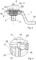
- FIG. 3 and FIG. 4 shows that around the gear housing 4 around an outer spline 8 is arranged, the mutually parallel and each having the same circumferential spacing teeth 9 to the rear, ie in the direction of the drive part 3, only up to a surrounding the transmission housing 4 over its entire circumference Groove 10 extend.
- the groove base 11 of the groove 10 is located on a diameter D1 which is smaller than the diameter D2 described by the tips 13 of the teeth 9.
- the spline 8 is a series of teeth 9 arranged circumferentially around the transmission housing 4, all of which extend in the longitudinal direction.
- the individual teeth 9 are each formed by tooth flanks 23 and a tooth tip 13.
- the teeth 9 are separated by gaps and tooth roots 24 and have equal distances from each other.
- an internal spline is arranged on the annular mounting flange 16. This cooperates with the spline 8 on the transmission housing 4 such that the support arm 1 is rotationally fixed to the transmission housing 4. Specifically, this means that the teeth of the internal spline of the mounting flange 16 in the intervene between the individual tooth flanks 23 of the teeth 9 of the spline 8 of the gear housing 4 interdental spaces, and vice versa.
- the fixing device 25 can assume a blocking or a release position, wherein the support arm 1 is fixed in the blocking position in the longitudinal direction of the rotation axis or output shaft 7 to the transmission housing 4.
- the locking element 20, preferably a ball, in the blocking position of the fixing device 25 extends partially into the groove 10 ( Fig. 4 ). Partially remains the locking member 20, even in the locked position, in the mounting flange sixteenth
- the actuating element 21 In order to move from the blocking position into a release position of the fixing device 25, which allows the support arm 1 or fastening flange 16 to be pulled down from the transmission housing 4, the actuating element 21 has to be actuated by the operator.
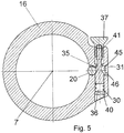
- the actuator 21 is within the mounting flange 16 tangentially to the axis of rotation 7 of the rotary screw displaceably arranged pin 31 which is biased against a compression spring 30.
- the pin 31 has a link or a recess 35 into which the ball 20 projects with a part of its spherical volume.
- the actuator 21 is composed of the guided in the bore 36 of the mounting flange 16 pin 31 and the end of the pen forming, enlarged head 37 together.
- Pin 31 and head 37 are preferably in two parts, but may also be formed in one piece or in one piece.
- the head 37 is extended in comparison to the pin 31, for example radially expanded.
- the radially expanded portion of the head 37 is located outside the bore 36 of the mounting flange 16 and can thus be operated by the operator.
- the head 37 can receive the pin 31 in a bore 41 of the head 37, for example by a screw connection.
- pin 31 are connected to head 37 in operative connection.
- the pin 31 is pressed against the force of a spring 30 in the bore 36.
- a compression spring 30 is supported, which is supported on its other side to a stopper 40 which closes the bore 36 outwardly.
- the plug 40 may be compressed in the bore 36 or fastened by screwing. When screwing the plug 40 has a corresponding external thread and the bore 36 to a corresponding internal thread.
- additional openings may be provided on the mounting flange 16, which allow access from the outside to the bore 36.
- a corresponding opening 45 can be arranged laterally of the pin 31 in the fastening flange 16.
- This bore 36 can be closed with a stopper 46. If the plugs 40, 46 are removed, the components arranged inside the bore 36 or in the fastening flange 16, in particular the pressure spring 30, the actuating element 21 and the locking element 20 can be removed from the bore 36 or the flange 16 and replaced. This is advantageous in particular for maintenance purposes.
- Fig. 5 is the mounting flange 16 together with fixing device 25 in the sectional plane VV gem.
- Fig. 3 shown. The viewing direction to be considered is indicated by corresponding arrows in Fig. 3 characterized.
- the fixing device 25 is in its blocking position. If the actuating element 21 is actuated, the head 37 together with the pin 31 shifts in the direction of the compression spring 30. The compression spring 30 is compressed or compressed and the locking element 20 or the ball can escape into the slot or recess 35 on the pin 31, and Although radially relative to the axis of rotation 7. As a result, the locking member 20 is in its release position. In this, the locking element 20 no longer extends into the groove 10 in contrast to the blocking position, and the support arm 1 can be withdrawn in the longitudinal direction of the output shaft 7 of the screwdriver 2.
- the locking element 20 and the actuating element 21 may be made of the same material or of different materials.
- the locking element 20 and the actuating element 21 may be made of metal.
Landscapes
- Engineering & Computer Science (AREA)
- Mechanical Engineering (AREA)
- Details Of Spanners, Wrenches, And Screw Drivers And Accessories (AREA)
- Snaps, Bayonet Connections, Set Pins, And Snap Rings (AREA)
- Gear Transmission (AREA)
- General Details Of Gearings (AREA)
Applications Claiming Priority (1)
| Application Number | Priority Date | Filing Date | Title |
|---|---|---|---|
| DE102017105025.6A DE102017105025A1 (de) | 2017-03-09 | 2017-03-09 | Anordnung aus einem Reaktionsmomente ableitenden Stützarm und einem Drehschrauber |
Publications (2)
| Publication Number | Publication Date |
|---|---|
| EP3372343A1 true EP3372343A1 (fr) | 2018-09-12 |
| EP3372343B1 EP3372343B1 (fr) | 2022-05-04 |
Family
ID=61526703
Family Applications (1)
| Application Number | Title | Priority Date | Filing Date |
|---|---|---|---|
| EP18159366.6A Active EP3372343B1 (fr) | 2017-03-09 | 2018-03-01 | Dispositif comportant un bras de support déviant le moment de réaction et un tournevis |
Country Status (8)
| Country | Link |
|---|---|
| US (1) | US10888980B2 (fr) |
| EP (1) | EP3372343B1 (fr) |
| JP (1) | JP7033959B2 (fr) |
| KR (1) | KR102550874B1 (fr) |
| CN (1) | CN108568772B (fr) |
| DE (1) | DE102017105025A1 (fr) |
| DK (1) | DK3372343T3 (fr) |
| ES (1) | ES2913925T3 (fr) |
Cited By (2)
| Publication number | Priority date | Publication date | Assignee | Title |
|---|---|---|---|---|
| CN110293503A (zh) * | 2019-07-03 | 2019-10-01 | 刘安胜 | 具有调节结构的螺栓拧动装置 |
| FR3105414A1 (fr) | 2019-12-24 | 2021-06-25 | Etablissements Georges Renault | Procédé de détermination du couple de serrage minimal d’un dispositif de vissage/dévissage, et dispositif correspondant |
Families Citing this family (1)
| Publication number | Priority date | Publication date | Assignee | Title |
|---|---|---|---|---|
| US20250162123A1 (en) * | 2023-11-17 | 2025-05-22 | Milwaukee Electric Tool Corporation | Reaction arm power tool with clutch mechanism |
Citations (5)
| Publication number | Priority date | Publication date | Assignee | Title |
|---|---|---|---|---|
| US4794825A (en) * | 1986-11-03 | 1989-01-03 | Atlantic-Caribbean Products, Inc. | Hydraulic power wrench |
| EP1329293A2 (fr) * | 2002-01-22 | 2003-07-23 | John K. Junkers | Bras de réaction ajustable pour outil de coulpe motorisé et outil de couple motorisé pourvu d'un tel bras |
| DE20301759U1 (de) * | 2003-02-05 | 2004-06-17 | Wagner, Paul-Heinz | Kraftschrauber |
| EP2210709A2 (fr) * | 2009-01-23 | 2010-07-28 | Lösomat Schraubtechnik Neef GmbH | Pied de support pour visseuses |
| DE202013004157U1 (de) * | 2013-05-06 | 2013-06-24 | LÖSOMAT-Schraubtechnik Neef GmbH | Vorrichtung zur Axialsicherung verzahnter Elemente |
Family Cites Families (11)
| Publication number | Priority date | Publication date | Assignee | Title |
|---|---|---|---|---|
| US4155278A (en) * | 1977-09-06 | 1979-05-22 | Cooper Industries, Inc. | Swivel head reaction bar nut runner |
| US7225707B2 (en) * | 2005-09-14 | 2007-06-05 | Brian Knopp | Torque wrench with quick-release gear set |
| CN2843767Y (zh) * | 2005-10-24 | 2006-12-06 | 山东同力达机电装备有限公司 | 电动定扭矩扳手自动定位反力机构 |
| US7451672B2 (en) * | 2006-01-11 | 2008-11-18 | Jetyd Corp. | Link attachment to torque wrench |
| SE531646C2 (sv) * | 2007-10-17 | 2009-06-16 | Atlas Copco Tools Ab | Skruvdragare med organ för övervakning av en reaktionsarm |
| US8042434B2 (en) * | 2008-01-24 | 2011-10-25 | Junkers John K | Safety torque intensifying tool |
| US7832310B2 (en) * | 2008-07-18 | 2010-11-16 | Junkers John K | Torque power tool |
| KR101165343B1 (ko) * | 2010-04-19 | 2012-07-18 | (주)세원피엠텍 | 왼나사 및 오른나사 겸용 토크 제어용 렌치 |
| SE535307C2 (sv) * | 2010-07-14 | 2012-06-26 | Atlas Copco Tools Ab | Låsmutter för en reaktionsarm |
| DE102015111570A1 (de) * | 2015-07-16 | 2017-01-19 | Jörg Hohmann | Drehschrauber |
| CN205415470U (zh) * | 2016-03-21 | 2016-08-03 | 上海虎啸电动工具有限公司 | 一种电动扭矩扳手 |
-
2017
- 2017-03-09 DE DE102017105025.6A patent/DE102017105025A1/de not_active Withdrawn
-
2018
- 2018-03-01 ES ES18159366T patent/ES2913925T3/es active Active
- 2018-03-01 DK DK18159366.6T patent/DK3372343T3/da active
- 2018-03-01 EP EP18159366.6A patent/EP3372343B1/fr active Active
- 2018-03-03 US US15/911,073 patent/US10888980B2/en active Active
- 2018-03-07 JP JP2018040610A patent/JP7033959B2/ja active Active
- 2018-03-08 KR KR1020180027515A patent/KR102550874B1/ko active Active
- 2018-03-09 CN CN201810192394.3A patent/CN108568772B/zh active Active
Patent Citations (5)
| Publication number | Priority date | Publication date | Assignee | Title |
|---|---|---|---|---|
| US4794825A (en) * | 1986-11-03 | 1989-01-03 | Atlantic-Caribbean Products, Inc. | Hydraulic power wrench |
| EP1329293A2 (fr) * | 2002-01-22 | 2003-07-23 | John K. Junkers | Bras de réaction ajustable pour outil de coulpe motorisé et outil de couple motorisé pourvu d'un tel bras |
| DE20301759U1 (de) * | 2003-02-05 | 2004-06-17 | Wagner, Paul-Heinz | Kraftschrauber |
| EP2210709A2 (fr) * | 2009-01-23 | 2010-07-28 | Lösomat Schraubtechnik Neef GmbH | Pied de support pour visseuses |
| DE202013004157U1 (de) * | 2013-05-06 | 2013-06-24 | LÖSOMAT-Schraubtechnik Neef GmbH | Vorrichtung zur Axialsicherung verzahnter Elemente |
Cited By (2)
| Publication number | Priority date | Publication date | Assignee | Title |
|---|---|---|---|---|
| CN110293503A (zh) * | 2019-07-03 | 2019-10-01 | 刘安胜 | 具有调节结构的螺栓拧动装置 |
| FR3105414A1 (fr) | 2019-12-24 | 2021-06-25 | Etablissements Georges Renault | Procédé de détermination du couple de serrage minimal d’un dispositif de vissage/dévissage, et dispositif correspondant |
Also Published As
| Publication number | Publication date |
|---|---|
| KR20180103740A (ko) | 2018-09-19 |
| JP7033959B2 (ja) | 2022-03-11 |
| US10888980B2 (en) | 2021-01-12 |
| KR102550874B1 (ko) | 2023-07-03 |
| DE102017105025A1 (de) | 2018-09-13 |
| CN108568772A (zh) | 2018-09-25 |
| CN108568772B (zh) | 2021-07-30 |
| DK3372343T3 (da) | 2022-06-20 |
| ES2913925T3 (es) | 2022-06-06 |
| EP3372343B1 (fr) | 2022-05-04 |
| JP2018149672A (ja) | 2018-09-27 |
| US20180257204A1 (en) | 2018-09-13 |
Similar Documents
| Publication | Publication Date | Title |
|---|---|---|
| EP2750873B1 (fr) | Système de couplage rapide pour la fixation d'une tête interchangeable sur un outil de pressage | |
| DE102007044251B4 (de) | Drehmomentwerkzeug und Verfahren zum Festziehen oder Lösen von Verbindungen | |
| EP3205454B1 (fr) | Outil de montage, son utilisation et procédé de fixation d'une douille filetée | |
| DE202010017882U1 (de) | Spannfutter für ein Werkzeug | |
| EP2837467A1 (fr) | Unité de serrage, en particulier pour l'utilisation dans un centre d'usinage ou un centre de tournage ou fraisage | |
| EP2897763B1 (fr) | Système de serrage à entraînement rotatif | |
| EP3372343B1 (fr) | Dispositif comportant un bras de support déviant le moment de réaction et un tournevis | |
| DE102009000901B4 (de) | Dreistufige Ventilschaltanordnung | |
| DE102012218530A1 (de) | Aufsatzvorrichtung für ein Bohrsystem sowie Bohrsystem zum Ausbohren eines Verbindungselementes | |
| DE102019103917A1 (de) | Greif- oder Spannvorrichtung mit einer Brems und/oder Festsetzeinheit | |
| EP2216555B1 (fr) | Dispositif de serrage | |
| EP1566238B1 (fr) | Système électrique de mouvement linéaire avec un accouplement direct entre un système vis-écrou et un module moteur | |
| DE202012101492U1 (de) | Nietsetzgerät mit abnehmbarer Hülse | |
| DE102010060790A1 (de) | Werkzeug zur Montage eines Sicherungsrings | |
| EP2514564A1 (fr) | Dispositif de vissage et de dévissage d'un écrou | |
| DE102007023807B4 (de) | Umschaltmittel für Schrauber mit zwei Abtrieben | |
| DE102008001252A1 (de) | Werkzeugmaschine, insbesondere Handwerkzeugmaschine | |
| DE102007007636B3 (de) | Abzieher | |
| DE19942292C2 (de) | Zwischenglied für eine Handschrauberwelle | |
| DE202016106681U1 (de) | Montagewerkzeug zur Befestigung eines Gewindeeinsatzes | |
| DE19819251B4 (de) | Handnietgerät zum Setzen von Blindnietmuttern | |
| EP2949427A1 (fr) | Outil destiné à fixer un connecteur à vis sur un câble électrique | |
| DE202012101491U1 (de) | Nietsetzgerät mit einem abnehmbaren Zylinder | |
| EP4010604B1 (fr) | Accouplement pour établir une liaison rigide entre deux arbres et agencement d'arbres avec un accouplement | |
| EP3409839B1 (fr) | Système de changement rapide pour attacher le bras d'une pelleteuse à un outil de travail |
Legal Events
| Date | Code | Title | Description |
|---|---|---|---|
| PUAI | Public reference made under article 153(3) epc to a published international application that has entered the european phase |
Free format text: ORIGINAL CODE: 0009012 |
|
| STAA | Information on the status of an ep patent application or granted ep patent |
Free format text: STATUS: THE APPLICATION HAS BEEN PUBLISHED |
|
| AK | Designated contracting states |
Kind code of ref document: A1 Designated state(s): AL AT BE BG CH CY CZ DE DK EE ES FI FR GB GR HR HU IE IS IT LI LT LU LV MC MK MT NL NO PL PT RO RS SE SI SK SM TR |
|
| AX | Request for extension of the european patent |
Extension state: BA ME |
|
| STAA | Information on the status of an ep patent application or granted ep patent |
Free format text: STATUS: REQUEST FOR EXAMINATION WAS MADE |
|
| 17P | Request for examination filed |
Effective date: 20190215 |
|
| RBV | Designated contracting states (corrected) |
Designated state(s): AL AT BE BG CH CY CZ DE DK EE ES FI FR GB GR HR HU IE IS IT LI LT LU LV MC MK MT NL NO PL PT RO RS SE SI SK SM TR |
|
| STAA | Information on the status of an ep patent application or granted ep patent |
Free format text: STATUS: EXAMINATION IS IN PROGRESS |
|
| 17Q | First examination report despatched |
Effective date: 20200723 |
|
| GRAP | Despatch of communication of intention to grant a patent |
Free format text: ORIGINAL CODE: EPIDOSNIGR1 |
|
| STAA | Information on the status of an ep patent application or granted ep patent |
Free format text: STATUS: GRANT OF PATENT IS INTENDED |
|
| INTG | Intention to grant announced |
Effective date: 20211117 |
|
| GRAS | Grant fee paid |
Free format text: ORIGINAL CODE: EPIDOSNIGR3 |
|
| GRAA | (expected) grant |
Free format text: ORIGINAL CODE: 0009210 |
|
| STAA | Information on the status of an ep patent application or granted ep patent |
Free format text: STATUS: THE PATENT HAS BEEN GRANTED |
|
| AK | Designated contracting states |
Kind code of ref document: B1 Designated state(s): AL AT BE BG CH CY CZ DE DK EE ES FI FR GB GR HR HU IE IS IT LI LT LU LV MC MK MT NL NO PL PT RO RS SE SI SK SM TR |
|
| REG | Reference to a national code |
Ref country code: GB Ref legal event code: FG4D Free format text: NOT ENGLISH |
|
| REG | Reference to a national code |
Ref country code: CH Ref legal event code: EP |
|
| REG | Reference to a national code |
Ref country code: AT Ref legal event code: REF Ref document number: 1488518 Country of ref document: AT Kind code of ref document: T Effective date: 20220515 |
|
| REG | Reference to a national code |
Ref country code: DE Ref legal event code: R096 Ref document number: 502018009534 Country of ref document: DE |
|
| REG | Reference to a national code |
Ref country code: IE Ref legal event code: FG4D Free format text: LANGUAGE OF EP DOCUMENT: GERMAN |
|
| REG | Reference to a national code |
Ref country code: ES Ref legal event code: FG2A Ref document number: 2913925 Country of ref document: ES Kind code of ref document: T3 Effective date: 20220606 |
|
| REG | Reference to a national code |
Ref country code: DK Ref legal event code: T3 Effective date: 20220614 |
|
| REG | Reference to a national code |
Ref country code: FI Ref legal event code: FGE |
|
| REG | Reference to a national code |
Ref country code: LT Ref legal event code: MG9D |
|
| REG | Reference to a national code |
Ref country code: NL Ref legal event code: MP Effective date: 20220504 |
|
| PG25 | Lapsed in a contracting state [announced via postgrant information from national office to epo] |
Ref country code: SE Free format text: LAPSE BECAUSE OF FAILURE TO SUBMIT A TRANSLATION OF THE DESCRIPTION OR TO PAY THE FEE WITHIN THE PRESCRIBED TIME-LIMIT Effective date: 20220504 Ref country code: PT Free format text: LAPSE BECAUSE OF FAILURE TO SUBMIT A TRANSLATION OF THE DESCRIPTION OR TO PAY THE FEE WITHIN THE PRESCRIBED TIME-LIMIT Effective date: 20220905 Ref country code: NO Free format text: LAPSE BECAUSE OF FAILURE TO SUBMIT A TRANSLATION OF THE DESCRIPTION OR TO PAY THE FEE WITHIN THE PRESCRIBED TIME-LIMIT Effective date: 20220804 Ref country code: NL Free format text: LAPSE BECAUSE OF FAILURE TO SUBMIT A TRANSLATION OF THE DESCRIPTION OR TO PAY THE FEE WITHIN THE PRESCRIBED TIME-LIMIT Effective date: 20220504 Ref country code: LT Free format text: LAPSE BECAUSE OF FAILURE TO SUBMIT A TRANSLATION OF THE DESCRIPTION OR TO PAY THE FEE WITHIN THE PRESCRIBED TIME-LIMIT Effective date: 20220504 Ref country code: HR Free format text: LAPSE BECAUSE OF FAILURE TO SUBMIT A TRANSLATION OF THE DESCRIPTION OR TO PAY THE FEE WITHIN THE PRESCRIBED TIME-LIMIT Effective date: 20220504 Ref country code: BG Free format text: LAPSE BECAUSE OF FAILURE TO SUBMIT A TRANSLATION OF THE DESCRIPTION OR TO PAY THE FEE WITHIN THE PRESCRIBED TIME-LIMIT Effective date: 20220804 |
|
| PG25 | Lapsed in a contracting state [announced via postgrant information from national office to epo] |
Ref country code: RS Free format text: LAPSE BECAUSE OF FAILURE TO SUBMIT A TRANSLATION OF THE DESCRIPTION OR TO PAY THE FEE WITHIN THE PRESCRIBED TIME-LIMIT Effective date: 20220504 Ref country code: PL Free format text: LAPSE BECAUSE OF FAILURE TO SUBMIT A TRANSLATION OF THE DESCRIPTION OR TO PAY THE FEE WITHIN THE PRESCRIBED TIME-LIMIT Effective date: 20220504 Ref country code: LV Free format text: LAPSE BECAUSE OF FAILURE TO SUBMIT A TRANSLATION OF THE DESCRIPTION OR TO PAY THE FEE WITHIN THE PRESCRIBED TIME-LIMIT Effective date: 20220504 Ref country code: IS Free format text: LAPSE BECAUSE OF FAILURE TO SUBMIT A TRANSLATION OF THE DESCRIPTION OR TO PAY THE FEE WITHIN THE PRESCRIBED TIME-LIMIT Effective date: 20220904 |
|
| PG25 | Lapsed in a contracting state [announced via postgrant information from national office to epo] |
Ref country code: SM Free format text: LAPSE BECAUSE OF FAILURE TO SUBMIT A TRANSLATION OF THE DESCRIPTION OR TO PAY THE FEE WITHIN THE PRESCRIBED TIME-LIMIT Effective date: 20220504 Ref country code: SK Free format text: LAPSE BECAUSE OF FAILURE TO SUBMIT A TRANSLATION OF THE DESCRIPTION OR TO PAY THE FEE WITHIN THE PRESCRIBED TIME-LIMIT Effective date: 20220504 Ref country code: RO Free format text: LAPSE BECAUSE OF FAILURE TO SUBMIT A TRANSLATION OF THE DESCRIPTION OR TO PAY THE FEE WITHIN THE PRESCRIBED TIME-LIMIT Effective date: 20220504 Ref country code: EE Free format text: LAPSE BECAUSE OF FAILURE TO SUBMIT A TRANSLATION OF THE DESCRIPTION OR TO PAY THE FEE WITHIN THE PRESCRIBED TIME-LIMIT Effective date: 20220504 Ref country code: CZ Free format text: LAPSE BECAUSE OF FAILURE TO SUBMIT A TRANSLATION OF THE DESCRIPTION OR TO PAY THE FEE WITHIN THE PRESCRIBED TIME-LIMIT Effective date: 20220504 |
|
| REG | Reference to a national code |
Ref country code: DE Ref legal event code: R097 Ref document number: 502018009534 Country of ref document: DE |
|
| PLBE | No opposition filed within time limit |
Free format text: ORIGINAL CODE: 0009261 |
|
| STAA | Information on the status of an ep patent application or granted ep patent |
Free format text: STATUS: NO OPPOSITION FILED WITHIN TIME LIMIT |
|
| PG25 | Lapsed in a contracting state [announced via postgrant information from national office to epo] |
Ref country code: AL Free format text: LAPSE BECAUSE OF FAILURE TO SUBMIT A TRANSLATION OF THE DESCRIPTION OR TO PAY THE FEE WITHIN THE PRESCRIBED TIME-LIMIT Effective date: 20220504 |
|
| 26N | No opposition filed |
Effective date: 20230207 |
|
| PG25 | Lapsed in a contracting state [announced via postgrant information from national office to epo] |
Ref country code: SI Free format text: LAPSE BECAUSE OF FAILURE TO SUBMIT A TRANSLATION OF THE DESCRIPTION OR TO PAY THE FEE WITHIN THE PRESCRIBED TIME-LIMIT Effective date: 20220504 |
|
| P01 | Opt-out of the competence of the unified patent court (upc) registered |
Effective date: 20230530 |
|
| PG25 | Lapsed in a contracting state [announced via postgrant information from national office to epo] |
Ref country code: MC Free format text: LAPSE BECAUSE OF FAILURE TO SUBMIT A TRANSLATION OF THE DESCRIPTION OR TO PAY THE FEE WITHIN THE PRESCRIBED TIME-LIMIT Effective date: 20220504 |
|
| REG | Reference to a national code |
Ref country code: CH Ref legal event code: PL |
|
| REG | Reference to a national code |
Ref country code: BE Ref legal event code: MM Effective date: 20230331 |
|
| PG25 | Lapsed in a contracting state [announced via postgrant information from national office to epo] |
Ref country code: LU Free format text: LAPSE BECAUSE OF NON-PAYMENT OF DUE FEES Effective date: 20230301 |
|
| REG | Reference to a national code |
Ref country code: IE Ref legal event code: MM4A |
|
| PG25 | Lapsed in a contracting state [announced via postgrant information from national office to epo] |
Ref country code: LI Free format text: LAPSE BECAUSE OF NON-PAYMENT OF DUE FEES Effective date: 20230331 Ref country code: IE Free format text: LAPSE BECAUSE OF NON-PAYMENT OF DUE FEES Effective date: 20230301 Ref country code: CH Free format text: LAPSE BECAUSE OF NON-PAYMENT OF DUE FEES Effective date: 20230331 |
|
| PG25 | Lapsed in a contracting state [announced via postgrant information from national office to epo] |
Ref country code: BE Free format text: LAPSE BECAUSE OF NON-PAYMENT OF DUE FEES Effective date: 20230331 |
|
| REG | Reference to a national code |
Ref country code: AT Ref legal event code: MM01 Ref document number: 1488518 Country of ref document: AT Kind code of ref document: T Effective date: 20230301 |
|
| PG25 | Lapsed in a contracting state [announced via postgrant information from national office to epo] |
Ref country code: AT Free format text: LAPSE BECAUSE OF NON-PAYMENT OF DUE FEES Effective date: 20230301 |
|
| PG25 | Lapsed in a contracting state [announced via postgrant information from national office to epo] |
Ref country code: AT Free format text: LAPSE BECAUSE OF NON-PAYMENT OF DUE FEES Effective date: 20230301 |
|
| PG25 | Lapsed in a contracting state [announced via postgrant information from national office to epo] |
Ref country code: BG Free format text: LAPSE BECAUSE OF FAILURE TO SUBMIT A TRANSLATION OF THE DESCRIPTION OR TO PAY THE FEE WITHIN THE PRESCRIBED TIME-LIMIT Effective date: 20220504 |
|
| PG25 | Lapsed in a contracting state [announced via postgrant information from national office to epo] |
Ref country code: BG Free format text: LAPSE BECAUSE OF FAILURE TO SUBMIT A TRANSLATION OF THE DESCRIPTION OR TO PAY THE FEE WITHIN THE PRESCRIBED TIME-LIMIT Effective date: 20220504 |
|
| PGFP | Annual fee paid to national office [announced via postgrant information from national office to epo] |
Ref country code: ES Payment date: 20250429 Year of fee payment: 8 |
|
| PG25 | Lapsed in a contracting state [announced via postgrant information from national office to epo] |
Ref country code: CY Free format text: LAPSE BECAUSE OF FAILURE TO SUBMIT A TRANSLATION OF THE DESCRIPTION OR TO PAY THE FEE WITHIN THE PRESCRIBED TIME-LIMIT; INVALID AB INITIO Effective date: 20180301 |
|
| PG25 | Lapsed in a contracting state [announced via postgrant information from national office to epo] |
Ref country code: HU Free format text: LAPSE BECAUSE OF FAILURE TO SUBMIT A TRANSLATION OF THE DESCRIPTION OR TO PAY THE FEE WITHIN THE PRESCRIBED TIME-LIMIT; INVALID AB INITIO Effective date: 20180301 |
|
| PG25 | Lapsed in a contracting state [announced via postgrant information from national office to epo] |
Ref country code: GR Free format text: LAPSE BECAUSE OF FAILURE TO SUBMIT A TRANSLATION OF THE DESCRIPTION OR TO PAY THE FEE WITHIN THE PRESCRIBED TIME-LIMIT; INVALID AB INITIO Effective date: 20180301 |
|
| PG25 | Lapsed in a contracting state [announced via postgrant information from national office to epo] |
Ref country code: TR Free format text: LAPSE BECAUSE OF FAILURE TO SUBMIT A TRANSLATION OF THE DESCRIPTION OR TO PAY THE FEE WITHIN THE PRESCRIBED TIME-LIMIT Effective date: 20220504 |
|
| PGFP | Annual fee paid to national office [announced via postgrant information from national office to epo] |
Ref country code: GB Payment date: 20260324 Year of fee payment: 9 |
|
| PGFP | Annual fee paid to national office [announced via postgrant information from national office to epo] |
Ref country code: DE Payment date: 20260319 Year of fee payment: 9 Ref country code: DK Payment date: 20260324 Year of fee payment: 9 |
|
| PGFP | Annual fee paid to national office [announced via postgrant information from national office to epo] |
Ref country code: FI Payment date: 20260323 Year of fee payment: 9 Ref country code: IT Payment date: 20260319 Year of fee payment: 9 |
|
| PGFP | Annual fee paid to national office [announced via postgrant information from national office to epo] |
Ref country code: FR Payment date: 20260320 Year of fee payment: 9 |