EP3376038A1 - Groupe motopompe - Google Patents
Groupe motopompe Download PDFInfo
- Publication number
- EP3376038A1 EP3376038A1 EP17160837.5A EP17160837A EP3376038A1 EP 3376038 A1 EP3376038 A1 EP 3376038A1 EP 17160837 A EP17160837 A EP 17160837A EP 3376038 A1 EP3376038 A1 EP 3376038A1
- Authority
- EP
- European Patent Office
- Prior art keywords
- pressure
- valve element
- suction
- openings
- switching
- Prior art date
- Legal status (The legal status is an assumption and is not a legal conclusion. Google has not performed a legal analysis and makes no representation as to the accuracy of the status listed.)
- Granted
Links
Images













Classifications
-
- F—MECHANICAL ENGINEERING; LIGHTING; HEATING; WEAPONS; BLASTING
- F04—POSITIVE - DISPLACEMENT MACHINES FOR LIQUIDS; PUMPS FOR LIQUIDS OR ELASTIC FLUIDS
- F04D—NON-POSITIVE-DISPLACEMENT PUMPS
- F04D1/00—Radial-flow pumps, e.g. centrifugal pumps; Helico-centrifugal pumps
-
- F—MECHANICAL ENGINEERING; LIGHTING; HEATING; WEAPONS; BLASTING
- F04—POSITIVE - DISPLACEMENT MACHINES FOR LIQUIDS; PUMPS FOR LIQUIDS OR ELASTIC FLUIDS
- F04D—NON-POSITIVE-DISPLACEMENT PUMPS
- F04D29/00—Details, component parts, or accessories
- F04D29/40—Casings; Connections of working fluid
- F04D29/42—Casings; Connections of working fluid for radial or helico-centrifugal pumps
- F04D29/426—Casings; Connections of working fluid for radial or helico-centrifugal pumps especially adapted for liquid pumps
- F04D29/4293—Details of fluid inlet or outlet
-
- F—MECHANICAL ENGINEERING; LIGHTING; HEATING; WEAPONS; BLASTING
- F04—POSITIVE - DISPLACEMENT MACHINES FOR LIQUIDS; PUMPS FOR LIQUIDS OR ELASTIC FLUIDS
- F04D—NON-POSITIVE-DISPLACEMENT PUMPS
- F04D13/00—Pumping installations or systems
- F04D13/02—Units comprising pumps and their driving means
- F04D13/06—Units comprising pumps and their driving means the pump being electrically driven
-
- F—MECHANICAL ENGINEERING; LIGHTING; HEATING; WEAPONS; BLASTING
- F04—POSITIVE - DISPLACEMENT MACHINES FOR LIQUIDS; PUMPS FOR LIQUIDS OR ELASTIC FLUIDS
- F04D—NON-POSITIVE-DISPLACEMENT PUMPS
- F04D13/00—Pumping installations or systems
- F04D13/02—Units comprising pumps and their driving means
- F04D13/06—Units comprising pumps and their driving means the pump being electrically driven
- F04D13/0686—Mechanical details of the pump control unit
-
- F—MECHANICAL ENGINEERING; LIGHTING; HEATING; WEAPONS; BLASTING
- F04—POSITIVE - DISPLACEMENT MACHINES FOR LIQUIDS; PUMPS FOR LIQUIDS OR ELASTIC FLUIDS
- F04D—NON-POSITIVE-DISPLACEMENT PUMPS
- F04D15/00—Control, e.g. regulation, of pumps, pumping installations or systems
- F04D15/0005—Control, e.g. regulation, of pumps, pumping installations or systems by using valves
-
- F—MECHANICAL ENGINEERING; LIGHTING; HEATING; WEAPONS; BLASTING
- F04—POSITIVE - DISPLACEMENT MACHINES FOR LIQUIDS; PUMPS FOR LIQUIDS OR ELASTIC FLUIDS
- F04D—NON-POSITIVE-DISPLACEMENT PUMPS
- F04D15/00—Control, e.g. regulation, of pumps, pumping installations or systems
- F04D15/0005—Control, e.g. regulation, of pumps, pumping installations or systems by using valves
- F04D15/0016—Control, e.g. regulation, of pumps, pumping installations or systems by using valves mixing-reversing- or deviation valves
-
- F—MECHANICAL ENGINEERING; LIGHTING; HEATING; WEAPONS; BLASTING
- F04—POSITIVE - DISPLACEMENT MACHINES FOR LIQUIDS; PUMPS FOR LIQUIDS OR ELASTIC FLUIDS
- F04D—NON-POSITIVE-DISPLACEMENT PUMPS
- F04D15/00—Control, e.g. regulation, of pumps, pumping installations or systems
- F04D15/0005—Control, e.g. regulation, of pumps, pumping installations or systems by using valves
- F04D15/0022—Control, e.g. regulation, of pumps, pumping installations or systems by using valves throttling valves or valves varying the pump inlet opening or the outlet opening
-
- F—MECHANICAL ENGINEERING; LIGHTING; HEATING; WEAPONS; BLASTING
- F04—POSITIVE - DISPLACEMENT MACHINES FOR LIQUIDS; PUMPS FOR LIQUIDS OR ELASTIC FLUIDS
- F04D—NON-POSITIVE-DISPLACEMENT PUMPS
- F04D15/00—Control, e.g. regulation, of pumps, pumping installations or systems
- F04D15/0066—Control, e.g. regulation, of pumps, pumping installations or systems by changing the speed, e.g. of the driving engine
-
- F—MECHANICAL ENGINEERING; LIGHTING; HEATING; WEAPONS; BLASTING
- F04—POSITIVE - DISPLACEMENT MACHINES FOR LIQUIDS; PUMPS FOR LIQUIDS OR ELASTIC FLUIDS
- F04D—NON-POSITIVE-DISPLACEMENT PUMPS
- F04D29/00—Details, component parts, or accessories
- F04D29/08—Sealings
- F04D29/16—Sealings between pressure and suction sides
- F04D29/165—Sealings between pressure and suction sides especially adapted for liquid pumps
- F04D29/167—Sealings between pressure and suction sides especially adapted for liquid pumps of a centrifugal flow wheel
-
- F—MECHANICAL ENGINEERING; LIGHTING; HEATING; WEAPONS; BLASTING
- F04—POSITIVE - DISPLACEMENT MACHINES FOR LIQUIDS; PUMPS FOR LIQUIDS OR ELASTIC FLUIDS
- F04D—NON-POSITIVE-DISPLACEMENT PUMPS
- F04D29/00—Details, component parts, or accessories
- F04D29/40—Casings; Connections of working fluid
- F04D29/42—Casings; Connections of working fluid for radial or helico-centrifugal pumps
- F04D29/44—Fluid-guiding means, e.g. diffusers
- F04D29/46—Fluid-guiding means, e.g. diffusers adjustable
- F04D29/48—Fluid-guiding means, e.g. diffusers adjustable for unidirectional fluid flow in reversible pumps
- F04D29/486—Fluid-guiding means, e.g. diffusers adjustable for unidirectional fluid flow in reversible pumps especially adapted for liquid pumps
-
- F—MECHANICAL ENGINEERING; LIGHTING; HEATING; WEAPONS; BLASTING
- F04—POSITIVE - DISPLACEMENT MACHINES FOR LIQUIDS; PUMPS FOR LIQUIDS OR ELASTIC FLUIDS
- F04D—NON-POSITIVE-DISPLACEMENT PUMPS
- F04D29/00—Details, component parts, or accessories
- F04D29/70—Suction grids; Strainers; Dust separation; Cleaning
- F04D29/708—Suction grids; Strainers; Dust separation; Cleaning specially for liquid pumps
Definitions
- the invention relates to a pump unit with at least one rotationally driven impeller and a valve element, which is rotatable between at least two switching positions.
- circulating pump units which have integrated valve means to switch flow paths through the pump unit can.
- a circulation pump is for example off DE 1 958 277 known.
- the pump unit shown there has a valve element, which is connected in a first switching position so that water is pumped in a heating system by a boiler and then by subsequent heating circuits and back into the boiler. In a second switching position, the water is only circulated in the heating circuit. That is, here the valve element can switch between two suction ports.
- the pump unit according to the invention has at least one rotationally driven impeller, that is, it is designed as a centrifugal pump unit. More preferably, the pump unit is designed as Um Georglzpumpenaggregat, in particular as Bankungsum stiilzpumpenaggregat.
- the pump unit may preferably have an electric drive motor. This can be further preferably designed as a wet-running electric drive motor, in which a split tube or a split pot separates the rotor space from the stator, so that the rotor rotates in the liquid to be conveyed.
- the pump unit according to the invention also has a valve device with at least one movable valve element, which is rotatable about an axis of rotation between at least two switching positions.
- the valve element has a first end face extending transversely to its axis of rotation. In this first end face, a suction opening is formed in the central area, which is in engagement with a suction mouth of the impeller, so that the liquid conveyed by the impeller enters through the suction opening into the suction mouth of the impeller.
- the valve element has, at its first end face, in addition to an annular pressure surface surrounding the suction opening, which adjoins a pressure chamber surrounding the impeller. That is, the valve element is acted upon at this pressure surface by the output-side pressure of the impeller.
- This embodiment allows additional functionalities of the valve device or the valve element, because the pressure prevailing on the output side of the impeller can for example be exploited to cause movements of the valve element.
- it is possible to perform also pressure-side switching operations since the valve element faces the pressure chamber and is in communication with the pressure side.
- the valve element can perform suction-side switching or actuating functions, since the valve element is also connected via the suction opening to the suction side of the impeller.
- the valve element thus according to the invention has contact with the suction side and the pressure side, which allows a variety of switching functions.
- the axis of rotation of the valve element is located in alignment with a rotational axis of the impeller.
- the impeller is preferably designed as a closed impeller in such a way that the impeller is closed in a region surrounding the suction mouth frontally by a cover plate.
- the impeller is thus closed at that end face, which faces the valve element, through the cover plate in the peripheral region of the suction mouth.
- a peripheral edge of the suction mouth is sealingly engaged with a peripheral edge of the suction opening.
- an axially projecting collar of the suction mouth engage in an axially projecting collar of the suction opening or, conversely, an axially protruding collar of the suction opening can engage, for example, in a corresponding collar of the suction mouth.
- At least one pressure opening may be formed in the pressure surface of the valve element, which is flow-connected in at least one of the switching positions of the valve element with at least one pressure connection of the pump unit.
- a switching function can be achieved on the pressure side by liquid from a surrounding the impeller pressure chamber is guided through the pressure port through the valve element to the pressure port of the pump unit.
- the pressure connection can be closed so that the pressure opening is no longer in flow-conducting connection with the pressure connection, so that the flow path is interrupted.
- the valve element is further preferably drum-shaped with a circumferentially extending around the rotation axis peripheral wall, said first end face and one of these facing away in the direction of the axis of rotation second end face formed, wherein the peripheral wall is preferably formed closed.
- the peripheral wall may preferably have the shape of a circular cylinder, but could for example also have a conical shape, wherein it further preferably tapers in the direction away from the impeller. It is possible to provide required openings for the valve functionality only in the end faces of the valve element. Alternatively or additionally, however, switching openings can also be arranged in the peripheral wall, in particular if these are conical Has shape. Due to the drum-shaped structure, there is space for different channels or flow paths in the interior of the valve element in order to be able to provide different switching functions.
- the valve element is opposite at least two connection openings and has at least one connection in its interior, which depending on the positioning or switching position of the valve element either one of the connection openings with the suction port or optionally one of the connection openings with a pressure opening in the pressure surface or connects at least two connection openings with each other.
- the valve element can be designed for a wide variety of switching functionalities.
- a switching function and in particular switching function can be realized on the pressure side in the manner described above.
- connection openings By selectively connecting one or more connection openings with the suction opening of the valve element can be performed by changing the switching position of the valve element, a switching function on the suction side of the impeller, for example, a flow path between two suction-side inputs are switched.
- a switching function on the suction side of the impeller, for example, a flow path between two suction-side inputs are switched.
- a switching function can be made independent of the flow path through the impeller. It is also conceivable to design the valve element with one or more connections in such a way that it can be brought into contact with the suction side or the pressure side of the impeller by changing the switching position.
- two connections may be provided be, one to a pressure port and a suction port, which each terminate in a switching opening, so that either the switching opening to the suction port or the switching port, which is in communication with the pressure port, can be brought into connection with one and the same port opening.
- connection openings of a peripheral wall or preferably the said second end face of the valve element, which is remote from the impeller are opposite.
- the connection openings are preferably formed on the inner wall of a valve and / or pump housing. If now openings or switching openings are formed in the corresponding peripheral wall or end face of the valve element, these can be brought into coincidence by rotation of the valve element with the connection openings, so that a flow path is opened, or be moved away from the switching openings so that a closed wall the connection openings opposite, so that they are closed and the respective flow path is interrupted.
- the suction opening of the valve element is connected via a connection in the interior of the valve element with at least one suction-side switching opening and preferably with at least two suction-side switching openings in the valve element, wherein the switching opening is arranged or the switching openings are arranged so that they depend on the Positioning of the valve element with two suction-side connection openings can be brought to cover different.
- a switching function is possible by opening a flow path when a switching port is opposed to a port, or the flow path is closed when the switching opening is moved away from the connection opening, so that the connection opening is closed by a wall of the valve element.
- a mixing function can be achieved in which the degree of overlap of at least one switching opening with two connection openings is varied so that the cross-sectional ratio of the two free connection openings is changed to each other, so that flows from the two connection openings changed in their relation to each other and mixed in different ratio can be.
- the at least two suction-side switching openings are radially spaced from the axis of rotation of the valve element at different distances. This is particularly advantageous when the switching openings are formed in said second end face of the valve element.
- two substantially annular zones with connection openings can be created in the valve or pump housing opposite to these switching openings, wherein each zone conveys liquid of a different temperature, which are then mixed differently by the valve position in the manner described.
- This embodiment is also advantageous if such mixing functionalities distributed over the circumference at different angular positions of the valve element to be realized.
- the pressure surface of the valve element preferably at least one and more preferably a plurality of pressure openings are formed, which are connected via a connection in the interior of the valve element with one or more pressure-side switching openings, which are arranged such that they depend on the switching position of the valve element in each case with a pressure-side Connection opening can be brought to cover.
- the pressure-side switching openings are also preferred in the second axial end face of the valve element, that is, the end facing away from the impeller and / or located in a circumferential surface of the valve element. Switching functions on the pressure side of the impeller, that is, on the output side of the pump unit, can be provided via these pressure openings and pressure-side switching openings, for example in order to selectively convey heating water into different heating circuits. This functionality can be realized particularly preferably simultaneously with the mixing functionality on the suction side of the impeller, as described above.
- the pressure-side switching openings are radially further spaced from the axis of rotation of the valve element than the suction-side switching openings. This makes it possible to arrange the pressure-side and suction-side switching openings in the same, preferably the second end face of the valve element, so that they do not interfere with their functionality.
- the plurality of pressure-side connection openings and a plurality of pressure-side switching openings are arranged such that in a first switching position of the valve element, only a pressure-side switching opening of a pressure-side connection opening is opposite and in at least a second switching position at least two pressure-side switching openings each opposite a pressure-side connection opening.
- connection openings can also be realized with more than two connection openings, wherein in a plurality of connection openings preferably as many possible switching positions of the valve element are provided, that each of the connection openings can be opened individually, wherein the other switching openings are closed at the same time, and moreover preferably in other switching positions several or all switching openings can be opened simultaneously.
- the arrangement is chosen so that all possible combinations of connection openings can be opened simultaneously. This can be achieved for example by appropriate distribution of the switching openings and connection openings along a circular line in certain angular positions about the axis of rotation of the valve element.
- the pressure-side switching openings and pressure-side connection openings are arranged such that each of the pressure-side connection openings in each case a specific switching position of the valve element individually opposite to a pressure-side switching opening and preferably opposite in at least one other switching position more of the pressure-side connection openings each a pressure-side switching opening.
- different heating circuits can be opened independently and in combination if the pump unit is used as a heating circulation pump unit in a heating system.
- the suction-side switching openings are arranged such that in each of the switching positions of the valve element, in which one or more pressure-side switching openings in each case opposite a pressure-side connection opening, opposite at least one suction-side switching opening of a suction-side connection opening.
- the switching positions are defined by the angular position of the pressure-side switching openings and pressure-side connection openings.
- the change in the degree of opening of a suction-side flow path is then effected by a change in the positioning of the valve element within this switching position by the valve element can be rotated by a certain amount to an angular position defining the switching position back and forth.
- the flow in the region of the suction-side switching opening can be varied by changing the positioning and, in particular, a change in a mixture between two flow paths can be varied by changing the positioning from two suction-side connection openings. That is, the movement required to change the positioning for influencing the flow on the suction side is superimposed on the movement of the valve element between the switching positions which perform switching functions on the pressure side.
- the suction-side switching openings are arranged such that in each of the switching positions of the valve element at least one suction-side switching opening is opposite to two suction-side connection openings. More preferably, two suction-side switching openings may be arranged so that each switching opening in each case faces a suction-side connection opening.
- the arrangement is such that by changing the positioning of the valve element within the switching position of the degree of overlap of the suction-side switching opening and the suction-side switching openings can be varied with the suction-side connection openings.
- one of the suction-side connection openings can be further released, for example, and at the same time the other suction-side connection opening can be closed further, so that the mixture of the liquid flows from the two connection openings can be changed.
- the pressure-side switching opening remains in the desired switching position, that is, in register with a desired pressure-side connection opening, so that the switching position on the pressure side of the pump unit remains unchanged from the change in the mixing ratio.
- the valve element between the individual switching positions is always moved by a predetermined angle, so that the set positioning of the suction-side switching openings is maintained even in the new switching position, that is, in particular a mixing ratio of two flows on the suction side of the change of Switch position on the pressure side is not affected.
- the valve element or the valve device in the pump unit according to the invention is preferably designed such that a change in the positioning of the valve element by its rotation takes place in an angular range which is smaller than an angle between the switching positions.
- the angle between two switching positions can be 18 °, while the angular range in which the positioning for influencing the flow on the suction side takes place in the range of +/- 5 ° to the angular position defined by the switching position.
- the valve element can be coupled to its movement by a magnetic, mechanical and / or hydraulic coupling with a rotor of a drive motor driving the impeller.
- the valve element can be driven by its own adjusting motor, which is preferably designed as a stepper motor.
- the separate adjusting motor and / or a coupling to the rotor of the impeller can also act via a gear on the valve element, so preferably takes place between the drive and the valve element, a reduction or translation into slow.
- the adjustment motor used or an electric drive motor of the pump unit, when it is used for movement of the valve element, is preferably equipped with a control device, which makes it possible to control the variable displacement motor or electric drive motor so that it in the desired angular steps can be rotated to move the valve element in desired angular steps between the switching positions and / or the various positions within the switching positions in the manner described above.
- An additional adjusting motor can preferably be controlled by the control device of the pump unit, which controls its drive motor.
- the valve element or the valve device with the valve element is designed and arranged such that the rotation angle between the individual switch positions correspond to a fixed uniform angular step or correspond to a multiple of a fixed angle step. So can the individual switch positions for example, at certain regular angles, for example 30 °, 45 °, 18 ° or the like apart. In this case, it is not necessary to have a switching position at each of these regular angular positions, but rather it is also possible for two switching positions to be spaced apart by a multiple or an integral multiple of a predefined fixed angular step. If a control device is present in the manner described above, then this is further preferably designed so that it can control the respective motor so that the valve element can be moved in the mentioned angular steps.
- the valve element is mounted so that it is linearly movable along its axis of rotation between an adjacent position in which the valve element rests against at least one contact surface, and a released position in which the valve element is spaced from the contact surface.
- a frictional connection between the valve element and contact surface can be achieved, which holds the valve element in the achieved angular position.
- Said movement can preferably be achieved by acting on the pressure surface pressure on the output side of the impeller.
- a return element for example in the form of a spring, which acts on the valve element in the opposite direction with a restoring force, so that it, when the pressure in the pressure chamber falls below a predetermined value, is moved back into a dissolved starting position.
- the contact surface is at least one sealing surface and more preferably a sealing surface surrounding a connection opening.
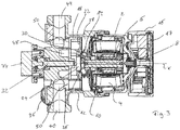
- the first embodiment according to Fig. 1 to 6 shows a pump unit in the form of a centrifugal pump unit, in which a valve device is integrated, which allows switching between four different heating circuits.
- the centrifugal pump unit or pump unit 1 has a stator or motor housing 2, in which an electric drive motor with a stator 4 and a rotor 6 is arranged.
- the rotor 6 is rotatably mounted on a rotor shaft 8.
- the electric drive motor shown is designed as a wet-running electric drive motor with a can or gap tube 10, which separates the stator with the stator 4 of the rotor chamber with the rotor 6 disposed therein, so that the rotor 6 rotates in the liquid to be conveyed.
- the motor housing 2 is connected to a pump housing 12, which simultaneously forms a valve housing. In the pump housing 12 rotates a rotatably connected to the rotor shaft 8 impeller 14th
- an electronics housing 16 is arranged with a control device 17 arranged therein.
- the control device 17 is used in particular for the control or regulation of the electric drive motor, wherein the electric drive motor is variable in particular in its rotational speed, to which the control device 17 may have a frequency converter. It is to be understood that the electronics housing 16 need not necessarily be arranged at the axial end of the motor housing 2, but could also be arranged at a different position.
- a valve element 18 is arranged next to the impeller 14.
- the valve element 18 is drum-shaped with a cup-shaped lower part 20 and the lower part 20 at its end facing the impeller 14 closing lid 22.
- the cover 22 has a central suction opening 24, which is in engagement with the suction mouth 26 of the impeller 14, wherein In this embodiment, an axially projecting collar of the suction opening 24 engages in the interior of the suction mouth 26.
- the area surrounding the suction opening 24 of the lid 22 forms a pressure surface which the Pressure chamber 28 in the vicinity of the impeller 14 faces.
- the pressure chamber 28 is that pressure chamber in which the liquid exits the impeller 14, that is, the space on the output side of the impeller 14, in which there is a higher pressure than on the suction side.
- the valve element 18 is thus connected both to the suction side in the region of the suction opening 24 in connection and to the pressure side on the pressure chamber 28 via the pressure surface formed by the cover 22.
- the impeller 14 is formed closed, that is, it is closed at its the valve element 18 facing side in the vicinity of the suction mouth 26 of an annular cover plate 30.
- the cover plate 30 ensures a separation between the suction and pressure area on the impeller 14.
- the valve member 18 is rotatably mounted on a shaft 32, wherein it can move to a certain extent in the axial direction X on the shaft 32.
- the shaft 32 is connected to an adjusting motor 34, which is preferably formed as a stepping motor with reduction gear.
- the adjusting motor 34 is likewise controlled by the control device 17.
- the pump housing 12 has a suction port or inlet 36 and four outputs or pressure ports 38, 40, 42 and 44.
- a regulating valve 46 is arranged in each case to adjust the flow through the respective pressure port 38, 40, 42, 44.
- the suction port 36 opens into an annular suction-side connection opening 48, which extends annularly around the axis of rotation X of the rotor 6, which is simultaneously the axis of rotation of the shaft 32 and thus of the valve element 18.
- the pressure ports 38, 40, 42, 44 open in the interior of the pump housing in a bottom surface, which extends transversely to the axis of rotation X, in each case in a pressure-side connection opening 50.
- pressure-side connection openings 50 there are four pressure-side connection openings 50, which are each offset by 90 ° at the angular positions of the pressure connections.
- the pressure-side connection openings are located in the bottom of the pump housing 2 on an annular surface which is arranged radially outside of the suction-side connection opening.
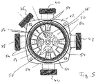
- the valve element 18 has in its interior a plurality, in this case twelve, connections which extend parallel to the axis of rotation X of a respective pressure opening 52 to a pressure-side switching opening 54 on the opposite, that is the impeller 14 facing away from the front end of the valve element 18.
- a pressure-side switching opening 54 on the opposite, that is the impeller 14 facing away from the front end of the valve element 18.
- four further suction-side switching openings 56 are arranged radially further inwardly to the pressure-side switching openings.
- connections between the pressure-side switching openings 54 and the pressure openings 52 are separated by walls from the remaining interior of the valve element 18, so that in the axial direction through the Valve element for a pressure-side connections between the pressure openings 52 and the pressure-side switching openings 54 and a suction-side connection of the suction-side switching openings 56 to the suction port 54 are made.
- the pressure-side switching openings 54 are arranged at the bottom of the valve element 18 so that they are spaced from the axis of rotation X as far as the pressure-side port openings 50 in the bottom of the pump housing 12. That is, the pressure-side port openings 50 are on a ring portion such that they a ring portion, in which the pressure-side switching openings 54 are arranged, opposite. Further, the pressure-side switching openings 54 and the pressure-side connection openings 50 suitably dimensioned to one another, so that they can be brought by appropriate rotation of the valve element 18 to cover.
- the suction-side switching openings 56 face the annular suction-side connection opening 48, so that there is always a connection from the suction connection 36 to the suction-side switching openings 56 and above to the suction opening 34.
- FIG. 6a shows a first switching position in which only the pressure port 40 is open or connected to the pressure chamber 38.
- the valve element 18 is rotated so that the pressure-side switching opening 54a is congruent to the pressure-side connection opening 50, which is connected to the pressure port 40.
- All other pressure-side switching openings 54 in the lower part 20 of the valve element 18, however, are opposite to the bottom regions of the pump housing 12. In particular, the remaining pressure-side connection openings 50 are covered and closed by the bottom of the lower part 20.
- the suction-side switching openings 56 are in communication with the suction-side connection opening 48, so that in this switching position the impeller 14 conveys liquid through the suction connection 36 toward the pressure connection 40.
- In the second switching position according to Fig. 6b are two pressure-side switching openings 54b, which are arranged diametrically opposite to each other, congruent to the pressure-side port openings 50 of the pressure ports 40 and 44 located so that the pump unit from the suction port 36 into the open outputs 40 and 44 promotes.
- Fig. 6d shows a further switching position in which only three of the pressure ports 38, 40, 42 and 44, namely the three pressure ports 38, 40 and 44 are open.
- the three pressure-side switching openings 54d are brought to coincide with the pressure-side connection openings 50 of the pressure connections 38, 40 and 44.
- the three pressure-side switching openings 54d each offset by 90 ° to each other, so that no pressure-side switching opening is formed in the lower part 20 at the associated fourth 90 ° position and so at this point the fourth remaining pressure-side connection opening 50 from the bottom of the lower part 20 and covers is closed. It is to be understood that by rotation of the valve element 18 by 90 ° each, the three other possible combinations, three of the pressure ports 38, 40, 42 and 44 to open, could be realized via the pressure-side switching openings 54d.
- Fig. 6e shows a further switching position in which two adjacent pressure ports are open at the same time.
- two further pressure-side switching openings 54e are formed in the valve element 18, which are offset by 90 ° to each other. Again, no corresponding pressure-side switching openings are formed at the two remaining associated 90 ° angle positions in the lower part 20, so that in this position, the two remaining pressure-side connection openings 50 are closed.
- the pressure-side switching openings 54e on the pressure side Connection openings 50 of the pressure ports 38 and 40 By turning the valve element 18 by 90 ° and the other three possible combinations of adjacent pressure ports on the pressure-side switching ports 54e can be opened.
- valve element 18 By appropriate angular position of the valve element 18 all possible combinations of the four pressure ports 38, 40, 42, 44 can be opened individually and in combination. Thus, a very simple distribution valve is created, which requires only a single drive and beyond can be integrated directly into the pump housing 12.
- the switching openings 54 are arranged in a grid of 18 ° steps, so that the various switching positions can be changed by rotation of the valve element 18 in steps of 18 ° or a multiple of 18 °.
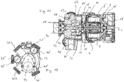
- the second embodiment according to Fig. 8 to 15 differs from the embodiment described above in that only three pressure-side circuits or connections can be supplied, but in addition a mixing valve is integrated into the pump unit.
- the pump housing 12 has in this embodiment, two suction ports 36a and 36b. Further, three pressure ports 38 ', 40' and 42 'are arranged on the pump housing 12, which open in the interior of the pump housing 12 in three offset by 120 ° to each other arranged pressure-side connection openings 50.
- the suction port 36a is in the bottom of the pump assembly 12 in communication with an outer annular opening 58, while the suction port 36b is in communication with an inner annular opening 60.
- a control disk 62 is arranged in this embodiment, which is in a fixed angular position, so that openings which form the pressure-side connection openings 50, the pressure-side connection openings 50 in the bottom of the pump housing 12 'are opposite.
- suction-side port openings 48 a are arranged in the control disk radially inwardly, which are in communication with the suction port 36 a, by facing the inner ring opening 60.
- three suction-side connection openings 48b are arranged at three angularly distributed angular positions. These suction-side port openings 48b are in communication with the suction port 36b.
- the valve element 18 ' has a similar construction to the valve element 18 according to the first embodiment, except that in this exemplary embodiment only six connections between six pressure openings 52 in the pressure surface formed by the cover 22' extend to six pressure-side switching openings 54 '.
- suction-side switching openings 56'a and 56'b are arranged at the bottom of the lower part 20 ', with the suction-side switching openings 56'a lying radially inward at a radial position corresponding to the positioning of the suction-side connection openings 48a.
- the suction-side switching openings 56'b are arranged radially further outward in an annular region, which lies opposite a ring region, in which the suction-side port openings 48b are located.
- the pressure-side switching openings are arranged in a grid of 20 ° increments, so that there are angular increments of 20 ° or a multiple of 20 ° between the switching positions.
- the remaining structure of the pump unit corresponds to the structure of the pump unit according to the first embodiment, so that reference is made to the relevant description.
- Fig. 12a to 12c three switching positions are shown, in each of which one of the pressure ports 38 ', 40' and 42 'is opened.
- the pressure port 40 ' is opened by facing the pressure-side switching port 54'a of a pressure-side port 50, which is connected to the pressure port 40'.
- the pressure-side switching opening 54'a is located in the bottom of the lower part 20 'of the valve element 18' so that starting from the pressure-side switching opening 54'a by 120 ° spaced no switching openings are provided, so that in this valve position or switching position, the other two pressure-side connection openings 50 are covered by the bottom of the lower part 20 'and thus closed.
- valve element 18 is the valve element 18 'rotated by 120 °, so that the pressure-side switching opening 54' a of the pressure port, which is connected to the pressure port 42 ', opposite.
- Fig. 12c shows a third switching position in which the valve element 18 'is again rotated by 180 ° about the axis of rotation X, so that the pressure-side switching opening 54'a the pressure-side port opening 50, which is connected to the pressure port 38', opposite.
- the valve element 18 can be slightly changed in its position by a small angular range (eg +/- 5 °), so that the opposite suction-side port openings 48a are slightly changed in coverage, so that the flow increases or can be downsized.
- the suction-side switching openings 56'b in their
- two of the three pressure ports 38 ', 40' and 42 ' are open in each case.
- two further pressure-side switching openings 54'b in the bottom of the lower part 20 'of the valve element 18' are used. These two switching openings 54'b are spaced apart by 120 °, wherein no switching opening is provided at the third associated position spaced apart by 120 °, so that in each case one of the pressure-side connection openings 50 is covered and closed.
- the two pressure-side switching openings 54'b cover the pressure-side connection openings 50 of the pressure connections 38 'and 40'.
- Fig. 13b In the switching position according to Fig. 13b is the valve element 18 'rotated by 120 °, so that in a similar manner, the pressure ports 40' and 42 'are opened by the switching openings 54'b cover the associated connection openings 50.
- the third possible shift position is in Fig. 13c shown, there are the pressure ports 38 'and 42' simultaneously open, while the third pressure port 40 'is closed.
- the mixing ratio of the flows from the two suction ports 36a and 36b can be changed by slightly changing the angular position about the reached switching position by the suction-side port openings 48a and 48b with the suction-side switching ports 56'a and 56'b different overlapping to be brought.
- the change in positioning is significantly smaller in angle than the change in the switching position.
- Fig. 14a to 14c Based on Fig. 14a to 14c another possible switching position is described in which all three pressure ports 38 ', 40', 42 'are opened.
- three pressure-side switching openings 54'c in the bottom of the lower part 20 'of the valve element 18' are used, which are arranged at 120 ° apart from each other.
- the pressure-side switching openings 54 described above are placed in this switching position so that they do not face any of the pressure-side connection openings 50, as in FIG Fig. 14a characterized.
- the pressure-side switching openings 54'c are each opposite one of the three pressure-side connection openings 50, these overlapping at least partially.
- FIG. 14c shows exactly the middle of the switching position in which the switching openings 54'c cover the pressure-side connection openings 50 exactly.
- the Figs. 14a and 14b show therefrom in two opposite directions of rotation slightly different positions, in which the mixing ratio is changed on the suction side in the manner previously described. In these positions, the pressure-side switching openings 54'c overlap the pressure-side connection openings 50 only partially.
- the suction-side connection openings 48a which lie radially inward, are completely closed. In this position, liquid will only come out of the suction port 36b sucked.
- the positioning according to Fig. 14b and Fig. 14c show different overlaps of the port openings 48a and 48b with the suction side switching ports 56'a and 56'b representing different mixture ratios.
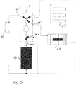
- a pump unit 1 according to the second embodiment can be used for example in a heating system, which in Fig. 15 is shown.
- the heating system has a heat source 64, which may be, for example, a gas boiler.
- a heat source 64 which may be, for example, a gas boiler.
- a secondary heat exchanger 70 is still provided for heating domestic water.
- the first suction port 36 a of the pump unit 1 is connected to the output of the heat source 64.
- the second suction port 36b is connected to the return of the heating circuits 66, 68 and the secondary heat exchanger 70 and thus supplies cooled water to the suction port 36b while supplying heated water to the suction port 36a.
- the first heating circuit 66 is connected to the pressure connection 38 ', the second heating circuit 68 and the pressure connection 42' of the secondary heat exchanger 70 are connected to the pressure connection 40 '. It can thus be switched between these three heating circuits, wherein in the manner described two or all three can be operated in parallel. At the same time a temperature adjustment by the mixture is possible.
- a mixing valve as it can be used for example for temperature adjustment for underfloor heating.
- the motor housing 2 with the electronics housing 16 corresponds to the embodiment described above .
- the pump housing 12 has two suction ports 72, 74, which terminate in the interior in each case at a suction-side connection opening 76 (76 a and 76 b).
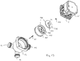
- the valve element 18 c is also drum-shaped in this third embodiment and consists of a cup-shaped lower part 20 c, which is closed on its side facing the impeller 14 by a cover 22 c. In the central region of the lid 22c, a suction opening 36 is formed.
- the valve element 18 c is rotatably mounted on an axis 78, which is arranged in the bottom of the pump housing 12.
- valve element 18c As in the examples described above, the axis of rotation X of the rotor shaft 8.
- the valve element 18c is also axially displaceable along the axis X and by a spring 80 in the in Fig. 20 shown rest position, in which the valve element 18 c is in a released position in which the lower part 20 c is not applied to the bottom of the pump housing 12, so that the valve element 18 c is substantially freely rotatable about the axis 78.
- the front end of the rotor shaft 8 which is designed as a coupling 82.
- the clutch 82 engages with a counter-coupling 110, which is non-rotatably arranged on the valve element 18c in engagement.
- the coupling 82 has tapered coupling surfaces, which essentially describe a saw tooth profile along a circumferential line in such a way that torque transmission from the coupling 82 to the counter coupling 110 is possible only in one direction of rotation, namely in the direction of rotation A in FIG Fig. 18 , In the opposite direction of rotation B, however, the clutch slips through, resulting in an axial movement of the valve element 18c.
- the direction of rotation B is the direction of rotation in which the pump unit is driven in normal operation.
- the direction of rotation A is used for targeted adjustment of the valve element 18c.
- the counter-coupling 110 from the clutch 82 by the pressure in the pressure chamber 28 except Intervention If the pressure in the pressure chamber 28 increases, acts as a pressure surface on the cover 22c, a pressure force which is opposite to the spring force of the spring 80 and exceeds, so that the valve element 18c is pressed into the applied position, which in Fig. 19 is shown.
- the lower part 20c is located on the bottom side of the pump housing 12, so that on the one hand, the valve member 18c is frictionally held and on the other hand a tight contact is achieved, which seals the pressure and the suction side in the manner described below against each other.
- the pump housing 12 has two suction ports 72 and 74, of which the suction port 72 in a suction-side connection opening 76a and the suction port 74 in a suction-side connection opening 76b in the bottom of the pump housing 12 in the interior, that is, the suction chamber opens into it.
- the lower part 20c of the valve element 18c has in its bottom an arcuate switching opening or opening 112, which extends substantially through 90 °.
- Fig. 21 a shows a first switching position, in which the opening 112 covers only the connection opening 76b, so that a flow path is given only from the suction connection 72 to the suction opening 24 and thus to the suction mouth 26 of the impeller 14.
- the second connection opening 76a is tightly closed by the bottom of the valve element 18c resting against its peripheral area.
- Fig. 21c shows the second switching position in which the opening 112 covers only the connection opening 76a, while the connection opening 76b is closed. In this switching position, only one flow path from the suction port 74 to the suction port 26 is open.
- Fig. 21b now shows an intermediate position in which the opening 112 covers both connection openings 76a and 76b, wherein the connection opening 76b is only partially released.
- a mixing ratio between the flows from the port ports 76a and 76b can be changed.
- the valve element 18 c can be adjusted in small steps to change the mixing ratio.
- Such a stepwise adjustment of the rotor shaft 8 can be caused in a special operating mode by the control device 17 in the electronics housing 16. That is, it is dispensed with a separate variable displacement motor.
- the drive motor is operated in the special operating mode in open-loop operation, wherein it can be controlled so that it can be rotated stepwise in desired angular positions.
- the required angular positions for setting the desired mixing ratio can be approached in a targeted manner, wherein regulation could take place via an output-side temperature sensor (not shown here).
- the centrifugal pump assembly with the integrated valve, as described above, characterized by the dashed line 1.
- the hydraulic circuit has a heat source 114 in the form of, for example, a gas boiler, the output of which opens into, for example, the suction connection 74 of the pump housing 12.
- a floor heating circuit 116 connects to the pressure connection 115 of the centrifugal pump assembly 1, the return of which is connected both to the inlet of the heat source 114 and to the suction connection 72 of the centrifugal pump assembly 1.
- a further heating circuit 120 can be supplied with a heat carrier, which has the output-side temperature of the heat source 114.
- the floor heating circuit 116 can be regulated in its flow temperature by mixing cold water from the return to the hot water on the output side of the heat source 114, changing the opening ratios of the suction-side connection openings 76a and 76b in the manner described above, the mixing ratio can be changed by rotation of the valve element 18c.
- the impeller 14 has a cover plate 30, so that a separation between the pressure chamber 28 and the suction region of the pump unit is given, wherein the surface of the lid 22c faces the pressure chamber 28 as a pressure surface.
- the suction opening 24 is also here with the suction mouth 26 in sealing engagement.
- the fourth embodiment according to Fig. 23 to 29 shows a pump unit or centrifugal pump unit, which in addition to the above-described mixer functionality in the third embodiment still has a switching functionality for additional supply of a secondary heat exchanger for domestic water heating.
- valve element 18d has, in addition to the opening 112, a passage 122 which extends from an opening 124 in the cover 22d to an opening in the bottom of the base 20d and thus connects the two axial ends of the valve element 18d. Furthermore, in the valve element 18d is still an only to the bottom, that is, to the bottom of the lower part 20d and thus to the suction chamber open arcuate bridging opening 126 is formed, which is closed to the pressure chamber 26 through the lid 22d.
- the pump housing 12 has, in addition to the pressure port 115 and the two previously described suction ports 74 and 72, a further port 128.
- the connection 128 opens into a connection opening or an inlet 130 in the bottom of the pump housing 12 in addition to the connection openings 76a and 76b into the suction chamber.
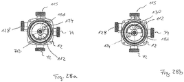
- the lid 22 d of the valve element 18 d is shown partially open to illustrate the position of the underlying openings.
- Fig. 28a shows a first switching position, in which the opening 112 of the connection opening 76b opposite, so that a flow connection from the suction port 12 to the suction port 26 of the impeller 14 is made. In the switching position according to Fig.
- the opening 112 is above the inlet 130, so that a flow connection from the port 128 to the suction port 24 and through this into the suction port 26 of the impeller 14 is provided.
- the opening 112 is located above the connection opening 76b, so that in turn a flow connection from the suction port 72 to the suction mouth 26 of the impeller 14 is given.
- a partial overlap of the switching opening or opening 124 and the through hole 122 with the input 76a takes place, so that a connection between the pressure chamber 28 and the suction port 74 is made, which acts as a pressure port.
- the bypass opening 126 covers the input 130 and a portion of the input 76a, thus also providing a connection from the terminal 128 via the input 130, the bypass opening 126 and the input 76a to the terminal 74.
- Fig. 28d shows a fourth switching position in which the passageway 122 completely covers the entrance 76a, so that the port 74 is connected via the passage 122 and the opening 124 with the pressure chamber 28. At the same time, the bridging opening 126 only covers the entrance 130. The opening 112 also covers the entrance 76b.
- the heating system in turn has a primary heat exchanger or a heat source 114, which may be, for example, a gas boiler.
- a first heating circuit 120 On the output side of the flow path is in a first heating circuit 120, which may be formed for example by conventional radiators or radiators.
- a flow path branches off to a secondary heat exchanger 70 for heating service water.
- the heating system further includes a floor heating circuit 116. The returns of the heating circuit 120 and the floor heating circuit 116 open into the suction port 72 on the pump housing 12. The return from the secondary heat exchanger 70 opens into the port 128, which, as will be described below, offers two functionalities.
- the connection 74 of the pump housing 12 is connected to the flow of the underfloor heating circuit 116.
- the impeller 14 promotes liquid from the suction port 72 via the pressure port 115 through the heat source 140 and the heating circuit 120 and back to the suction port 72.
- the valve element 18d in the second switching position which in Fig. 28b is shown, the plant is switched to domestic water operation, in this state, the pump assembly or the impeller 14 promotes liquid from the port 128, which serves as a suction port, through the pressure port 115, via the heat source 114 through the secondary heat exchanger 70 and back to the terminal 128.
- the valve element 18d in the third switching position which in Fig. 28c is shown, the underfloor heating circuit 116 is additionally supplied.
- the water flows into the suction mouth 26 of the impeller 14 and is supplied via the pressure connection 115 via the heat source 114 promoted in the manner described by the first heating circuit 120.
- the liquid on the output side of the impeller 14 exits from the pressure chamber 28 into the opening 124 and through the through-passage 122 and thus flows to the connection 74 and via this into the underfloor heating circuit 116.
- Fig. 28c The switch position shown flows simultaneously via the bridging opening 126 fluid via the port 128 and the input 130 into the port 74. That is, here water flows through the heat source 114 through the secondary heat exchanger 70 and the port 128 to the port 74. Since in this heating mode Secondary heat exchanger 70 is removed substantially no heat, so the port 74 hot water in addition to the cold water, which flows from the pressure chamber 28 via the passage 122 to the port 74, mixed. By varying the degree of opening via the valve position 18d, the amount of mixed warm water at the port 74 can be varied.
- Fig. 28d shows a switching position in which the admixture is turned off and the port 74 is exclusively in communication with the pressure chamber 28 directly.
- the various embodiments described above may be combined in various ways.
- the different types of drive described the valve element with different geometrical configurations of the valve element, as they have also been described above, can be combined essentially arbitrarily.
- the various valve functionalities (for example, mixing and switching) can also be implemented and combined with different drive types.
- These various combination possibilities which result from the preceding embodiments, are insofar expressly included in the invention.
- the pump housing is formed integrally with the housing in which the valve element is arranged. It is to be understood that in a corresponding manner a multi-part construction is possible.
- a separate housing from the pump housing could be provided for the valve element, which is connected via a pressure and a suction connection to the pump housing.
Landscapes
- Engineering & Computer Science (AREA)
- Mechanical Engineering (AREA)
- General Engineering & Computer Science (AREA)
- Physics & Mathematics (AREA)
- Fluid Mechanics (AREA)
- Structures Of Non-Positive Displacement Pumps (AREA)
Priority Applications (4)
| Application Number | Priority Date | Filing Date | Title |
|---|---|---|---|
| EP17160837.5A EP3376038B1 (fr) | 2017-03-14 | 2017-03-14 | Groupe motopompe |
| CN201880018580.3A CN110418894B (zh) | 2017-03-14 | 2018-03-12 | 泵机组 |
| PCT/EP2018/056082 WO2018166971A1 (fr) | 2017-03-14 | 2018-03-12 | Groupe motopompe |
| US16/493,177 US11512712B2 (en) | 2017-03-14 | 2018-03-12 | Pump assembly |
Applications Claiming Priority (1)
| Application Number | Priority Date | Filing Date | Title |
|---|---|---|---|
| EP17160837.5A EP3376038B1 (fr) | 2017-03-14 | 2017-03-14 | Groupe motopompe |
Publications (2)
| Publication Number | Publication Date |
|---|---|
| EP3376038A1 true EP3376038A1 (fr) | 2018-09-19 |
| EP3376038B1 EP3376038B1 (fr) | 2021-07-28 |
Family
ID=58347147
Family Applications (1)
| Application Number | Title | Priority Date | Filing Date |
|---|---|---|---|
| EP17160837.5A Active EP3376038B1 (fr) | 2017-03-14 | 2017-03-14 | Groupe motopompe |
Country Status (4)
| Country | Link |
|---|---|
| US (1) | US11512712B2 (fr) |
| EP (1) | EP3376038B1 (fr) |
| CN (1) | CN110418894B (fr) |
| WO (1) | WO2018166971A1 (fr) |
Families Citing this family (9)
| Publication number | Priority date | Publication date | Assignee | Title |
|---|---|---|---|---|
| CN111795004A (zh) * | 2020-05-11 | 2020-10-20 | 河海大学 | 一种带有双出口式蜗壳的中比转速离心泵 |
| US12297843B2 (en) * | 2022-06-08 | 2025-05-13 | Cooper-Standard Automotive Inc. | Multiport fluid pump with integrated valve |
| US20240068481A1 (en) * | 2022-08-24 | 2024-02-29 | Cooper-Standard Automotive Inc | Multiport fluid pump with reserve capacity impeller |
| US20240227502A9 (en) * | 2022-10-20 | 2024-07-11 | Cooper-Standard Automotive Inc | Pump with integrated valve and temperature sensor and a thermal management system including such a pump |
| CN116006521A (zh) * | 2023-02-08 | 2023-04-25 | 广东中南钢铁股份有限公司 | 一种立式泵用过滤装置及立式泵 |
| FR3146972B1 (fr) * | 2023-03-22 | 2025-05-23 | Valeo Systemes Thermiques | Dispositif combiné de vanne multivoies et de pompe |
| DE102023207225A1 (de) * | 2023-07-28 | 2025-01-30 | Robert Bosch Gesellschaft mit beschränkter Haftung | Pumpe zur Förderung eines Fluids |
| US12359606B2 (en) * | 2023-09-23 | 2025-07-15 | Cooper-Standard Automotive Inc. | Flow scheme with pump and switch |
| US12085081B1 (en) * | 2023-09-23 | 2024-09-10 | Cooper-Standard Automotive Inc. | Fluid pump and valve switch |
Citations (5)
| Publication number | Priority date | Publication date | Assignee | Title |
|---|---|---|---|---|
| DE7212196U (fr) * | Grundfos As | |||
| CH463896A (de) * | 1963-09-21 | 1968-10-15 | Louis Dipl Ing Siber | Misch- und Temperaturregelvorrichtung in einem Gehäuse mit mehreren Anschluss-Stutzen für Warmwasserheizungs- und -bereitungsanlagen |
| DE1958277B1 (de) | 1969-11-20 | 1971-02-25 | Karl Schichl | Umwaelzpumpe fuer warmwasser heizungsanlagen mit einem im pumpengehaeuse angeordneten vierwegemischerventil |
| FR2074692A2 (fr) * | 1970-01-19 | 1971-10-08 | Materiel Telephonique | Pompe-vanne, en particulier pour le chaffage central |
| DE4418153A1 (de) * | 1994-05-25 | 1995-11-30 | Wilo Gmbh | Kreiselpumpe |
Family Cites Families (5)
| Publication number | Priority date | Publication date | Assignee | Title |
|---|---|---|---|---|
| US5924432A (en) * | 1995-10-17 | 1999-07-20 | Whirlpool Corporation | Dishwasher having a wash liquid recirculation system |
| DE19809123B4 (de) * | 1998-03-04 | 2005-12-01 | Daimlerchrysler Ag | Wasserpumpe für den Kühlkreislauf einer Brennkraftmaschine |
| US9347369B2 (en) * | 2013-03-15 | 2016-05-24 | Gotek Energy, Inc. | Systems and methods for controlling compression in an engine, compressor, or pump |
| EP2818726B1 (fr) * | 2013-06-27 | 2017-08-23 | Grundfos Holding A/S | Pompe centrifuge avec roue à aubes déplaçable axialement pour l'alimentation de circuits différents |
| CN105745450B (zh) * | 2013-11-16 | 2017-10-24 | 博泽沃尔兹堡汽车零部件有限公司 | 电动冷却剂泵 |
-
2017
- 2017-03-14 EP EP17160837.5A patent/EP3376038B1/fr active Active
-
2018
- 2018-03-12 WO PCT/EP2018/056082 patent/WO2018166971A1/fr not_active Ceased
- 2018-03-12 CN CN201880018580.3A patent/CN110418894B/zh not_active Expired - Fee Related
- 2018-03-12 US US16/493,177 patent/US11512712B2/en active Active
Patent Citations (5)
| Publication number | Priority date | Publication date | Assignee | Title |
|---|---|---|---|---|
| DE7212196U (fr) * | Grundfos As | |||
| CH463896A (de) * | 1963-09-21 | 1968-10-15 | Louis Dipl Ing Siber | Misch- und Temperaturregelvorrichtung in einem Gehäuse mit mehreren Anschluss-Stutzen für Warmwasserheizungs- und -bereitungsanlagen |
| DE1958277B1 (de) | 1969-11-20 | 1971-02-25 | Karl Schichl | Umwaelzpumpe fuer warmwasser heizungsanlagen mit einem im pumpengehaeuse angeordneten vierwegemischerventil |
| FR2074692A2 (fr) * | 1970-01-19 | 1971-10-08 | Materiel Telephonique | Pompe-vanne, en particulier pour le chaffage central |
| DE4418153A1 (de) * | 1994-05-25 | 1995-11-30 | Wilo Gmbh | Kreiselpumpe |
Also Published As
| Publication number | Publication date |
|---|---|
| CN110418894B (zh) | 2021-11-05 |
| US11512712B2 (en) | 2022-11-29 |
| WO2018166971A1 (fr) | 2018-09-20 |
| US20200072238A1 (en) | 2020-03-05 |
| EP3376038B1 (fr) | 2021-07-28 |
| CN110418894A (zh) | 2019-11-05 |
Similar Documents
| Publication | Publication Date | Title |
|---|---|---|
| EP3376038B1 (fr) | Groupe motopompe | |
| EP0162342B1 (fr) | Insert de contrôle pour mélangeur sanitaire | |
| EP4058703B1 (fr) | Ensemble soupape de commande pour le réglage d'au moins deux écoulements de fluide dans un système de conduites | |
| EP3376037B1 (fr) | Groupe pompe centrifuge | |
| EP3376050B1 (fr) | Groupe pompe centrifuge | |
| WO2018167043A1 (fr) | Groupe motopompe | |
| EP3376036A1 (fr) | Groupe motopompe | |
| DE102016004706B3 (de) | Drehschieberventil | |
| DE102006053310A1 (de) | Ventil zur Steuerung von Volumenströmen | |
| EP3376051B1 (fr) | Groupe motopompe | |
| EP2932142B1 (fr) | Vanne mélangeuse multivoie et procédé de commande temporelle d'une vanne mélangeuse multivoie | |
| EP3267042A1 (fr) | Groupe motopompe | |
| EP3662205A1 (fr) | Dispositif de mélange et procédé de régulation de températion d'un écoulement de liquide | |
| EP3325859B1 (fr) | Module de répartition d'un agent de refroidissement pour un circuit de refroidissement | |
| WO2018166969A1 (fr) | Groupe motopompe | |
| EP3662204A1 (fr) | Unité de pompe de circulation | |
| WO1989002027A1 (fr) | Ventilateur a embrayage hydraulique a temperature controlee | |
| EP3376082B1 (fr) | Dispositif de soupape | |
| EP2080455A1 (fr) | Dispositif de verrouillage à plusieurs trajectoires pour liquides, notamment pour l'utilisation dans des automates de boissons | |
| EP2659169B1 (fr) | Soupape de commande de débits volumétriques | |
| EP2659168B1 (fr) | Soupape de commande de débits volumétriques | |
| EP3596342B1 (fr) | Groupe pompe centrifuge | |
| EP3376039B1 (fr) | Groupe pompe centrifuge | |
| WO2018166970A1 (fr) | Station domestique | |
| EP3438558A1 (fr) | Procédé de fonctionnement d'un dispositif mélangeur et ledit dispositif mélangeur |
Legal Events
| Date | Code | Title | Description |
|---|---|---|---|
| PUAI | Public reference made under article 153(3) epc to a published international application that has entered the european phase |
Free format text: ORIGINAL CODE: 0009012 |
|
| STAA | Information on the status of an ep patent application or granted ep patent |
Free format text: STATUS: THE APPLICATION HAS BEEN PUBLISHED |
|
| AK | Designated contracting states |
Kind code of ref document: A1 Designated state(s): AL AT BE BG CH CY CZ DE DK EE ES FI FR GB GR HR HU IE IS IT LI LT LU LV MC MK MT NL NO PL PT RO RS SE SI SK SM TR |
|
| AX | Request for extension of the european patent |
Extension state: BA ME |
|
| STAA | Information on the status of an ep patent application or granted ep patent |
Free format text: STATUS: REQUEST FOR EXAMINATION WAS MADE |
|
| 17P | Request for examination filed |
Effective date: 20190318 |
|
| RBV | Designated contracting states (corrected) |
Designated state(s): AL AT BE BG CH CY CZ DE DK EE ES FI FR GB GR HR HU IE IS IT LI LT LU LV MC MK MT NL NO PL PT RO RS SE SI SK SM TR |
|
| STAA | Information on the status of an ep patent application or granted ep patent |
Free format text: STATUS: EXAMINATION IS IN PROGRESS |
|
| 17Q | First examination report despatched |
Effective date: 20200625 |
|
| GRAP | Despatch of communication of intention to grant a patent |
Free format text: ORIGINAL CODE: EPIDOSNIGR1 |
|
| STAA | Information on the status of an ep patent application or granted ep patent |
Free format text: STATUS: GRANT OF PATENT IS INTENDED |
|
| INTG | Intention to grant announced |
Effective date: 20210303 |
|
| GRAS | Grant fee paid |
Free format text: ORIGINAL CODE: EPIDOSNIGR3 |
|
| GRAA | (expected) grant |
Free format text: ORIGINAL CODE: 0009210 |
|
| STAA | Information on the status of an ep patent application or granted ep patent |
Free format text: STATUS: THE PATENT HAS BEEN GRANTED |
|
| AK | Designated contracting states |
Kind code of ref document: B1 Designated state(s): AL AT BE BG CH CY CZ DE DK EE ES FI FR GB GR HR HU IE IS IT LI LT LU LV MC MK MT NL NO PL PT RO RS SE SI SK SM TR |
|
| REG | Reference to a national code |
Ref country code: GB Ref legal event code: FG4D Free format text: NOT ENGLISH |
|
| REG | Reference to a national code |
Ref country code: CH Ref legal event code: EP |
|
| REG | Reference to a national code |
Ref country code: DE Ref legal event code: R096 Ref document number: 502017010998 Country of ref document: DE |
|
| REG | Reference to a national code |
Ref country code: AT Ref legal event code: REF Ref document number: 1414966 Country of ref document: AT Kind code of ref document: T Effective date: 20210815 |
|
| REG | Reference to a national code |
Ref country code: IE Ref legal event code: FG4D Free format text: LANGUAGE OF EP DOCUMENT: GERMAN |
|
| REG | Reference to a national code |
Ref country code: LT Ref legal event code: MG9D |
|
| REG | Reference to a national code |
Ref country code: NL Ref legal event code: MP Effective date: 20210728 |
|
| PG25 | Lapsed in a contracting state [announced via postgrant information from national office to epo] |
Ref country code: SE Free format text: LAPSE BECAUSE OF FAILURE TO SUBMIT A TRANSLATION OF THE DESCRIPTION OR TO PAY THE FEE WITHIN THE PRESCRIBED TIME-LIMIT Effective date: 20210728 Ref country code: RS Free format text: LAPSE BECAUSE OF FAILURE TO SUBMIT A TRANSLATION OF THE DESCRIPTION OR TO PAY THE FEE WITHIN THE PRESCRIBED TIME-LIMIT Effective date: 20210728 Ref country code: NO Free format text: LAPSE BECAUSE OF FAILURE TO SUBMIT A TRANSLATION OF THE DESCRIPTION OR TO PAY THE FEE WITHIN THE PRESCRIBED TIME-LIMIT Effective date: 20211028 Ref country code: NL Free format text: LAPSE BECAUSE OF FAILURE TO SUBMIT A TRANSLATION OF THE DESCRIPTION OR TO PAY THE FEE WITHIN THE PRESCRIBED TIME-LIMIT Effective date: 20210728 Ref country code: PT Free format text: LAPSE BECAUSE OF FAILURE TO SUBMIT A TRANSLATION OF THE DESCRIPTION OR TO PAY THE FEE WITHIN THE PRESCRIBED TIME-LIMIT Effective date: 20211129 Ref country code: HR Free format text: LAPSE BECAUSE OF FAILURE TO SUBMIT A TRANSLATION OF THE DESCRIPTION OR TO PAY THE FEE WITHIN THE PRESCRIBED TIME-LIMIT Effective date: 20210728 Ref country code: FI Free format text: LAPSE BECAUSE OF FAILURE TO SUBMIT A TRANSLATION OF THE DESCRIPTION OR TO PAY THE FEE WITHIN THE PRESCRIBED TIME-LIMIT Effective date: 20210728 Ref country code: ES Free format text: LAPSE BECAUSE OF FAILURE TO SUBMIT A TRANSLATION OF THE DESCRIPTION OR TO PAY THE FEE WITHIN THE PRESCRIBED TIME-LIMIT Effective date: 20210728 Ref country code: BG Free format text: LAPSE BECAUSE OF FAILURE TO SUBMIT A TRANSLATION OF THE DESCRIPTION OR TO PAY THE FEE WITHIN THE PRESCRIBED TIME-LIMIT Effective date: 20211028 Ref country code: LT Free format text: LAPSE BECAUSE OF FAILURE TO SUBMIT A TRANSLATION OF THE DESCRIPTION OR TO PAY THE FEE WITHIN THE PRESCRIBED TIME-LIMIT Effective date: 20210728 |
|
| PG25 | Lapsed in a contracting state [announced via postgrant information from national office to epo] |
Ref country code: PL Free format text: LAPSE BECAUSE OF FAILURE TO SUBMIT A TRANSLATION OF THE DESCRIPTION OR TO PAY THE FEE WITHIN THE PRESCRIBED TIME-LIMIT Effective date: 20210728 Ref country code: LV Free format text: LAPSE BECAUSE OF FAILURE TO SUBMIT A TRANSLATION OF THE DESCRIPTION OR TO PAY THE FEE WITHIN THE PRESCRIBED TIME-LIMIT Effective date: 20210728 Ref country code: GR Free format text: LAPSE BECAUSE OF FAILURE TO SUBMIT A TRANSLATION OF THE DESCRIPTION OR TO PAY THE FEE WITHIN THE PRESCRIBED TIME-LIMIT Effective date: 20211029 |
|
| PG25 | Lapsed in a contracting state [announced via postgrant information from national office to epo] |
Ref country code: DK Free format text: LAPSE BECAUSE OF FAILURE TO SUBMIT A TRANSLATION OF THE DESCRIPTION OR TO PAY THE FEE WITHIN THE PRESCRIBED TIME-LIMIT Effective date: 20210728 |
|
| REG | Reference to a national code |
Ref country code: DE Ref legal event code: R097 Ref document number: 502017010998 Country of ref document: DE |
|
| PG25 | Lapsed in a contracting state [announced via postgrant information from national office to epo] |
Ref country code: SM Free format text: LAPSE BECAUSE OF FAILURE TO SUBMIT A TRANSLATION OF THE DESCRIPTION OR TO PAY THE FEE WITHIN THE PRESCRIBED TIME-LIMIT Effective date: 20210728 Ref country code: SK Free format text: LAPSE BECAUSE OF FAILURE TO SUBMIT A TRANSLATION OF THE DESCRIPTION OR TO PAY THE FEE WITHIN THE PRESCRIBED TIME-LIMIT Effective date: 20210728 Ref country code: RO Free format text: LAPSE BECAUSE OF FAILURE TO SUBMIT A TRANSLATION OF THE DESCRIPTION OR TO PAY THE FEE WITHIN THE PRESCRIBED TIME-LIMIT Effective date: 20210728 Ref country code: EE Free format text: LAPSE BECAUSE OF FAILURE TO SUBMIT A TRANSLATION OF THE DESCRIPTION OR TO PAY THE FEE WITHIN THE PRESCRIBED TIME-LIMIT Effective date: 20210728 Ref country code: CZ Free format text: LAPSE BECAUSE OF FAILURE TO SUBMIT A TRANSLATION OF THE DESCRIPTION OR TO PAY THE FEE WITHIN THE PRESCRIBED TIME-LIMIT Effective date: 20210728 Ref country code: AL Free format text: LAPSE BECAUSE OF FAILURE TO SUBMIT A TRANSLATION OF THE DESCRIPTION OR TO PAY THE FEE WITHIN THE PRESCRIBED TIME-LIMIT Effective date: 20210728 |
|
| PLBE | No opposition filed within time limit |
Free format text: ORIGINAL CODE: 0009261 |
|
| STAA | Information on the status of an ep patent application or granted ep patent |
Free format text: STATUS: NO OPPOSITION FILED WITHIN TIME LIMIT |
|
| 26N | No opposition filed |
Effective date: 20220429 |
|
| REG | Reference to a national code |
Ref country code: DE Ref legal event code: R082 Ref document number: 502017010998 Country of ref document: DE |
|
| PG25 | Lapsed in a contracting state [announced via postgrant information from national office to epo] |
Ref country code: MC Free format text: LAPSE BECAUSE OF FAILURE TO SUBMIT A TRANSLATION OF THE DESCRIPTION OR TO PAY THE FEE WITHIN THE PRESCRIBED TIME-LIMIT Effective date: 20210728 |
|
| REG | Reference to a national code |
Ref country code: CH Ref legal event code: PL |
|
| REG | Reference to a national code |
Ref country code: BE Ref legal event code: MM Effective date: 20220331 |
|
| PG25 | Lapsed in a contracting state [announced via postgrant information from national office to epo] |
Ref country code: LU Free format text: LAPSE BECAUSE OF NON-PAYMENT OF DUE FEES Effective date: 20220314 Ref country code: LI Free format text: LAPSE BECAUSE OF NON-PAYMENT OF DUE FEES Effective date: 20220331 Ref country code: IE Free format text: LAPSE BECAUSE OF NON-PAYMENT OF DUE FEES Effective date: 20220314 Ref country code: CH Free format text: LAPSE BECAUSE OF NON-PAYMENT OF DUE FEES Effective date: 20220331 |
|
| PG25 | Lapsed in a contracting state [announced via postgrant information from national office to epo] |
Ref country code: BE Free format text: LAPSE BECAUSE OF NON-PAYMENT OF DUE FEES Effective date: 20220331 |
|
| REG | Reference to a national code |
Ref country code: AT Ref legal event code: MM01 Ref document number: 1414966 Country of ref document: AT Kind code of ref document: T Effective date: 20220314 |
|
| PG25 | Lapsed in a contracting state [announced via postgrant information from national office to epo] |
Ref country code: AT Free format text: LAPSE BECAUSE OF NON-PAYMENT OF DUE FEES Effective date: 20220314 |
|
| PG25 | Lapsed in a contracting state [announced via postgrant information from national office to epo] |
Ref country code: HU Free format text: LAPSE BECAUSE OF FAILURE TO SUBMIT A TRANSLATION OF THE DESCRIPTION OR TO PAY THE FEE WITHIN THE PRESCRIBED TIME-LIMIT; INVALID AB INITIO Effective date: 20170314 |
|
| PG25 | Lapsed in a contracting state [announced via postgrant information from national office to epo] |
Ref country code: MK Free format text: LAPSE BECAUSE OF FAILURE TO SUBMIT A TRANSLATION OF THE DESCRIPTION OR TO PAY THE FEE WITHIN THE PRESCRIBED TIME-LIMIT Effective date: 20210728 Ref country code: CY Free format text: LAPSE BECAUSE OF FAILURE TO SUBMIT A TRANSLATION OF THE DESCRIPTION OR TO PAY THE FEE WITHIN THE PRESCRIBED TIME-LIMIT Effective date: 20210728 |
|
| PGFP | Annual fee paid to national office [announced via postgrant information from national office to epo] |
Ref country code: DE Payment date: 20240320 Year of fee payment: 8 Ref country code: GB Payment date: 20240320 Year of fee payment: 8 |
|
| PGFP | Annual fee paid to national office [announced via postgrant information from national office to epo] |
Ref country code: IT Payment date: 20240329 Year of fee payment: 8 Ref country code: FR Payment date: 20240328 Year of fee payment: 8 |
|
| PG25 | Lapsed in a contracting state [announced via postgrant information from national office to epo] |
Ref country code: TR Free format text: LAPSE BECAUSE OF FAILURE TO SUBMIT A TRANSLATION OF THE DESCRIPTION OR TO PAY THE FEE WITHIN THE PRESCRIBED TIME-LIMIT Effective date: 20210728 |
|
| PG25 | Lapsed in a contracting state [announced via postgrant information from national office to epo] |
Ref country code: MT Free format text: LAPSE BECAUSE OF FAILURE TO SUBMIT A TRANSLATION OF THE DESCRIPTION OR TO PAY THE FEE WITHIN THE PRESCRIBED TIME-LIMIT Effective date: 20210728 |
|
| REG | Reference to a national code |
Ref country code: DE Ref legal event code: R119 Ref document number: 502017010998 Country of ref document: DE |
|
| GBPC | Gb: european patent ceased through non-payment of renewal fee |
Effective date: 20250314 |
|
| PG25 | Lapsed in a contracting state [announced via postgrant information from national office to epo] |
Ref country code: DE Free format text: LAPSE BECAUSE OF NON-PAYMENT OF DUE FEES Effective date: 20251001 |
|
| PG25 | Lapsed in a contracting state [announced via postgrant information from national office to epo] |
Ref country code: GB Free format text: LAPSE BECAUSE OF NON-PAYMENT OF DUE FEES Effective date: 20250314 |
|
| PG25 | Lapsed in a contracting state [announced via postgrant information from national office to epo] |
Ref country code: FR Free format text: LAPSE BECAUSE OF NON-PAYMENT OF DUE FEES Effective date: 20250331 Ref country code: IT Free format text: LAPSE BECAUSE OF NON-PAYMENT OF DUE FEES Effective date: 20250314 |