EP3376108B1 - Feuerstätte - Google Patents
Feuerstätte Download PDFInfo
- Publication number
- EP3376108B1 EP3376108B1 EP18000239.6A EP18000239A EP3376108B1 EP 3376108 B1 EP3376108 B1 EP 3376108B1 EP 18000239 A EP18000239 A EP 18000239A EP 3376108 B1 EP3376108 B1 EP 3376108B1
- Authority
- EP
- European Patent Office
- Prior art keywords
- exhaust gas
- stove
- catalyst
- combustion chamber
- catalyst elements
- Prior art date
- Legal status (The legal status is an assumption and is not a legal conclusion. Google has not performed a legal analysis and makes no representation as to the accuracy of the status listed.)
- Active
Links
Images



Classifications
-
- F—MECHANICAL ENGINEERING; LIGHTING; HEATING; WEAPONS; BLASTING
- F24—HEATING; RANGES; VENTILATING
- F24B—DOMESTIC STOVES OR RANGES FOR SOLID FUELS; IMPLEMENTS FOR USE IN CONNECTION WITH STOVES OR RANGES
- F24B1/00—Stoves or ranges
- F24B1/006—Stoves or ranges incorporating a catalytic combustor
-
- F—MECHANICAL ENGINEERING; LIGHTING; HEATING; WEAPONS; BLASTING
- F23—COMBUSTION APPARATUS; COMBUSTION PROCESSES
- F23M—CASINGS, LININGS, WALLS OR DOORS SPECIALLY ADAPTED FOR COMBUSTION CHAMBERS, e.g. FIREBRIDGES; DEVICES FOR DEFLECTING AIR, FLAMES OR COMBUSTION PRODUCTS IN COMBUSTION CHAMBERS; SAFETY ARRANGEMENTS SPECIALLY ADAPTED FOR COMBUSTION APPARATUS; DETAILS OF COMBUSTION CHAMBERS, NOT OTHERWISE PROVIDED FOR
- F23M11/00—Safety arrangements
- F23M11/02—Preventing emission of flames or hot gases, or admission of air, through working or charging apertures
Definitions
- the invention relates to a fireplace, in particular a fireplace or tiled stove, fireplace insert or the like.
- Device for burning solid fuels such as logs, pressed wood such as brickets or pellets or mineral fuels such as coal or anthracite, with a fireplace body in which one of side walls, a rear wall, a floor and a combustion chamber door is provided, and with an exhaust gas duct connected to the combustion chamber, which is preferably arranged within an exhaust gas dome, and with a catalytic converter module assigned to the exhaust gas duct.
- fireplaces with a catalyst are known which are provided outside the fireplace.
- the fireplace of the type mentioned is characterized in that the catalytic converter module has several catalytic converter elements, that the catalytic converter elements are arranged at a distance from one another and each have a throughflow space for exhaust gas between them, the catalytic converter elements with intervals of at least 5 mm and a maximum of 40 mm to each other, so that there is a flow gap for exhaust gases, the catalyst elements being porous.
- the catalytic converter module contains catalytic converter elements which can be designed in a variety of ways depending on the application and possible arrangement in the exhaust gas duct or an exhaust gas dome of a fireplace.
- the catalyst module has several z. B. formed as catalyst plates on catalyst elements. These can be made from a wire mesh or a foam ceramic and be coated, for example, with a catalytically active material. These are arranged at a distance from one another with a minimum distance of 5 mm. Practical testing has shown that the distance should not be greater than 40 mm, however, in order to avoid blockages in the exhaust gas path and to ensure a sufficient supply of exhaust gas, preferably with a minimum distance of 10-20 mm.
- the flow resistance within the exhaust system must be kept low, whereby the exhaust gas cleaning effect is less than with forced flow through catalyst elements, but a diffusion effect in the form of a molecular movement of gas molecules and also of fine dust can cause a reduction in CO and also a reduction in fine dust and fine dust Hydrocarbon emissions.
- the fireplace is generally designated 1, which has a combustion chamber door 1.1, side walls 1.2 and a combustion chamber 1.3 located behind the combustion chamber door 1.1.
- An exhaust gas dome 2 with an exhaust gas nozzle 3 is connected to the combustion chamber 1.3 and thus contains an internal exhaust gas duct.
- the combustion chamber can be connected to a combustion air duct.
- a catalyst module generally numbered 4 is to be arranged within the exhaust gas dome 2 via a holding device, the holding device being designed in different ways can, for example, is circular, or has a rectangular frame and has several, in the exemplary embodiment shown, plate-shaped catalyst module elements 4.1, which are spaced apart from one another, so that there is therefore a through-flow gap for exhaust gases.
- FIG. 5 an embodiment of a fireplace insert is shown as a fireplace 1, wherein in Fig. 5 partially cut open a view into the combustion chamber 1.3 is made possible with the combustion chamber door 1.2, the side walls 1.3, the rear wall 1.4 and the combustion chamber floor 1.5.
- a transition from the combustion chamber 1.3 to the exhaust gas duct 7 is arranged in the exhaust gas dome 2, the catalytic converter module 4 with the catalytic converter module elements 4.1, specifically at a distance from one another so that the exhaust gas can flow through it.
Landscapes
- Engineering & Computer Science (AREA)
- Chemical & Material Sciences (AREA)
- Combustion & Propulsion (AREA)
- Mechanical Engineering (AREA)
- General Engineering & Computer Science (AREA)
- Chemical Kinetics & Catalysis (AREA)
- Chimneys And Flues (AREA)
Description
- Die Erfindung bezieht sich auf eine Feuerstätte, insbesondere einen Kamin- oder Kachelofen, Kamineinsatz oder dgl. Vorrichtung zur Verbrennung fester Brennstoffe wie Scheitholz, Holzpresslinge wie Brickets oder Pellets oder mineralischer Brennstoffe wie Kohle oder Anthrazit, mit einem Feuerstättenkorpus, in dem ein von Seitenwänden, einer Rückwand, einem Boden sowie einer Brennraumtür umgrenzter Brennraum vorgesehen ist, und der mit einer an den Brennraum angeschlossenen Abgasführung, die vorzugsweise innerhalb eines Abgasdomes angeordnet ist, und mit einem der Abgasführung zugeordneten Katalysatormodul.
- Mit Biomasse und mit Holz betriebene Feuerstätten leisten einen großen Beitrag zur Nutzung regenerativer Energien. Aus diesem Grund und auch wegen der damit einhergehenden Verbesserung der Wärmeversorgungssicherheiten in privaten Haushalten erfreuen sich diese Feuerstätten zunehmender Beliebtheit.
- Um die Emissionswerte bei solchen mit regenerativen Brennstoffen betriebenen Feuerstätten zu verringern, sind Feuerstätten mit einem Katalysator bekannt, die außerhalb der Feuerstätte vorgesehen sind.
- Aus der
GB 2 085 153 A US 4,319,556 A , derUS 2011/247,533 A1 , derUS 4,458,662 A , derWO 83/01673 A EP 2 166 287 A2 sind jeweils Feuerstätten der eingangs genannten Art bekannt, bei denen im Abgasweg jeweils ein Katalysatormodul vorgesehen ist, das in aller Regel aus einem Schaumfilter besteht. - Es ist Aufgabe der vorliegenden Erfindung eine Feuerstätte zur Verfügung zu stellen mit einem Katalysator, der Bestandteil der Feuerstätte sein kann.
- Zur Lösung dieser Aufgabe zeichnet sich die Feuerstätte der eingangs genannten Art dadurch aus, dass das Katalysatormodul mehrere Katalysatorelemente aufweist, dass die Katalvsatorelemente mit Abstand zueinander angeordnet sind und zwischen sich je einen Durchströmraum für Abgas aufweisen, wobei die Katalysatorelemente mit Abständen von mindestens 5 mm und maximal 40 mm zueinander angeordnet sind, so dass ein Durchströmspalt für Abgase gegeben ist, wobei die Katalysatorelemente porös ausgebildet sind.
- Damit ist eine Feuerstätte zur Verfügung gestellt, bei der das Katalysatormodul integraler Bestandteil der Feuerstätte ist und mit z. B. einer geeigneten Haltevorrichtung in der Abgasführung oder einem Abgasdom, der die Abgasführung aufweist, derart leicht montierbar und demontierbar integriert sein kann, dass eine optimale Abgasbehandlung ermöglicht ist. Das Katalysatormodul hat Katalysatorelemente enthalten, die variationsreich gestaltet sein können je nach Anwendungszweck und Anordnungsmöglichkeit in der Abgasführung bzw. eines Abgasdomes einer Feuerstätte.
- Das Katalysatormodul weist mehrere z. B. als Katalysatorplatten ausgebildete Katalysatorelemente auf. Diese können aus einem Drahtgestrick oder einer Schaumkeramik bestehen und beispielsweise mit einem katalytisch aktiven Material beschichtet sein. Diese sind mit einem Abstand zueinander angeordnet mit einem Mindestabstand von 5 mm. Aus der praktischen Erprobung hat sich gezeigt, dass der Abstand jedoch nicht größer als 40 mm betragen sollte, um Verblockungen des Abgasweges zu vermeiden und um eine hinreichende Abgaszufuhr sicherzustellen, bevorzugt mit einem Mindestabstand von 10 - 20 mm. Der Strömungswiderstand ist innerhalb der Abgasführung gering zu halten, wobei die Abgasreinigungswirkung zwar geringer ist als bei zwangsweiser Durchströmung von Katalysatorelementen, jedoch kann eine Diffusionswirkung in Gestalt einer Molekularbewegung von Gasmolekülen und auch von Feinstaub eine CO-Minderung hervorrufen und auch eine Verminderung von Feinstaub- und Kohlenwassersstoffemissionen.
- Weitere Vorteile und Ausgestaltungen der Erfindung ergeben sich aus weiteren Unteransprüchen, der nachfolgenden Beschreibung und der Zeichnung. In der Zeichnung zeigen:
- Fig. 1
- eine Vorderansicht auf ein Ausführungsbeispiel einer Feuerstätte nach der Erfindung;
- Fig. 2
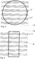
- eine Draufsicht auf ein Ausführungsbeispiel einer Haltevorrichtung mit Katalysatorplatten;
- Fig. 3
- eine Draufsicht auf ein alternatives Ausführungsbeispiel einer Haltevorrichtung mit Katalysatorplatten;
- Fig. 4
- eine Draufsicht auf ein weiteres Ausführungsbeispiel einer Haltevorrichtung mit integrierten Katalysatorplatten;
- Fig. 5
- eine perspektivisch Darstellung eines (teilweise geöffnet dargestellten) Ausführungsbeispiels einer Feuerstätte mit integrierten Katalysatorplatten;
- Fig. 6
- eine Ansicht von hinten auf das Ausführungsbeispiel nach
Fig. 5 und - Fig. 7
- eine Seitenansicht des Ausführungsbeispiels nach
Fig. 5 . - In der Zeichnung sind grundsätzlich übereinstimmende Teile mit übereinstimmenden Bezugsziffern versehen.
- In
Fig. 1 ist allgemein mit 1 die Feuerstätte bezeichnet, die eine Brennraumtür 1.1 aufweist, Seitenwände 1.2 und einen hinter der Brennraumtür 1.1 gelegenen Brennraum 1.3. An den Brennraum 1.3 ist ein Abgasdom 2 mit einem Abgasstutzen 3 angeschlossen, der mithin eine innere Abgasführung beinhaltet. Zudem kann der Brennraum an eine Verbrennungsluftführung angeschlossen sein. Innerhalb des Abgasdomes 2 ist über eine Haltevorrichtung ein allgemein mit 4 beziffertes Katalysatormodul anzuordnen, wobei die Haltevorrichtung verschiedenfach gestaltet sein kann, beispielsweise kreisrund ist, oder einen rechteckigen Rahmen aufweist und mehrere, in dem gezeigten Ausführungsbeispiel plattenförmig ausgebildete Katalysatormodulelemente 4.1 aufweist, die zueinander einen Abstand aufweisen, so dass mithin ein Durchströmspalt für Abgase gegeben ist. - In den
Figuren 5 bis 7 ist ein Ausführungsbeispiel eines Kamineinsatzes als Feuerstätte 1 dargestellt, wobei inFig. 5 teilweise aufgeschnitten ein Blick in den Brennraum 1.3 ermöglicht ist mit der Brennraumtür 1.2, den Seitenwänden 1.3, der Rückwand 1.4 und dem Brennraumboden 1.5. An dem Brennraum 1.3 schließt sich die Abgasführung 7 an, zu der auch der Abgasdom 2 gehört. Ein Übergang von Brennraum 1.3 in die Abgasführung 7 ist in dem Abgasdom 2 das Katalysatormodul 4 mit den Katalysatormodulelementen 4.1 angeordnet, und zwar mit Abstand zueinander, so dass es von dem Abgas durchströmbar ist.
Claims (10)
- Feuerstätte (1), insbesondere Kamin- oder Kachelofen, Kamineinsatz oder dgl. Vorrichtung zur Verbrennung fester Brennstoffe wie Scheitholz, Holzpresslinge wie Brickets oder Pellets oder mineralischer Brennstoffe wie Kohle oder Anthrazit, mit einem Feuerstättenkorpus, in dem ein von Seitenwänden (1.2), einer Rückwand (1.4), einem Boden (1.5) sowie einer Brennraumtür (1.1) umgrenzter Brennraum (1.3) vorgesehen ist, und mit einer an den Brennraum (1.3) angeschlossenen Abgasführung (7), die vorzugsweise zumindest teilweise innerhalb eines Abgasdomes (2) anordenbar ist, wobei der Abgasführung (7) ein Katalysatormodul (4) zugeordnet ist, wobei das Katalysatormodul (4) mehrere Katalysatorelemente (4.1) aufweist, wobei die Katalysatorelemente (4.1) mit Abständen von mindestens 5 mm und maximal 40 mm zueinander angeordnet sind und zwischen sich einen Durchströmraum für Abgas aufweisen, so dass ein Durchströmspalt für Abgase gegeben ist, dadurch gekennzeichnet, dass die Katalysatorelemente (4.1) porös ausgebildet sind.
- Feuerstätte (1) nach Anspruch 1, dadurch gekennzeichnet, dass das Katalysatormodul (4) zwischen dem Brennraum (1.3) und dem Eintritt in die Abgasführung (7) vorgesehen ist.
- Feuerstätte nach Anspruch 1 oder 2, dadurch gekennzeichnet, dass die Katalysatorelemente (4.1) als poröse Schaumkeramik- oder Drahtgestrickelemente ausgebildet sind.
- Feuerstätte nach einem der Ansprüche 1 bis 3, dadurch gekennzeichnet, dass die Katalysatorelemente (4.1) mit katalytisch aktivem Material belegt oder beschichtet sind.
- Feuerstätte nach einem der Ansprüche 1 bis 4, dadurch gekennzeichnet, dass die Katalysatorelemente (4.1) mit Abständen von mindestens 10 mm bis 20 mm zueinander angeordnet sind.
- Feuerstätte nach einem der Ansprüche 1 bis 5, dadurch gekennzeichnet, dass die Katalysatorelemente (4.1) als Katalysatorplatten ausgebildet sind.
- Feuerstätte nach einem der Ansprüche 1 bis 6, dadurch gekennzeichnet, dass die Katalysatorelemente (4.1) in einer Haltevorrichtung (5) angeordnet sind.
- Feuerstätte nach Anspruch 7, dadurch gekennzeichnet, dass die Haltevorrichtung (5) durch Schnellvorschlüsse montierbar und demontierbar ist.
- Feuerstätte nach Anspruch 7 oder 8, dadurch gekennzeichnet, dass die Haltevorrichtung (5) über einem Bajonettverschluss an einem Abgasdom (2) der Feuerstätte (1) befestigbar ist.
- Feuerstätte nach einem der Ansprüche 7 bis 9, dadurch gekennzeichnet, dass die Haltevorrichtung (5) über eine Steckverbindung (6) im Abgasdom (2) befestigbar ist.
Priority Applications (1)
| Application Number | Priority Date | Filing Date | Title |
|---|---|---|---|
| PL18000239T PL3376108T3 (pl) | 2017-03-14 | 2018-03-09 | Instalacja spalania |
Applications Claiming Priority (1)
| Application Number | Priority Date | Filing Date | Title |
|---|---|---|---|
| DE202017001335.5U DE202017001335U1 (de) | 2017-03-14 | 2017-03-14 | Feuerstätte |
Publications (2)
| Publication Number | Publication Date |
|---|---|
| EP3376108A1 EP3376108A1 (de) | 2018-09-19 |
| EP3376108B1 true EP3376108B1 (de) | 2021-06-23 |
Family
ID=58774000
Family Applications (1)
| Application Number | Title | Priority Date | Filing Date |
|---|---|---|---|
| EP18000239.6A Active EP3376108B1 (de) | 2017-03-14 | 2018-03-09 | Feuerstätte |
Country Status (3)
| Country | Link |
|---|---|
| EP (1) | EP3376108B1 (de) |
| DE (1) | DE202017001335U1 (de) |
| PL (1) | PL3376108T3 (de) |
Families Citing this family (1)
| Publication number | Priority date | Publication date | Assignee | Title |
|---|---|---|---|---|
| DE102021130740A1 (de) * | 2021-11-24 | 2023-05-25 | Ulrich Brunner Ofen- und Heiztechnik Gesellschaft für Guß- und Stahlkonstruktionen mbH | Einzelfeuerstätte mit einer Abgashaube |
Family Cites Families (6)
| Publication number | Priority date | Publication date | Assignee | Title |
|---|---|---|---|---|
| US4373507A (en) * | 1980-10-09 | 1983-02-15 | Jamestown Group | Stove construction |
| US4319556A (en) * | 1981-03-09 | 1982-03-16 | Jamestown Group | Catalytic stove |
| US4458662A (en) * | 1981-10-28 | 1984-07-10 | Condar Co. | Catalytic stove |
| WO1983001673A1 (en) * | 1981-10-28 | 1983-05-11 | Barnett, Stockton, G. | Catalytic stove |
| FR2939870B1 (fr) * | 2008-12-17 | 2013-06-07 | Fondis Sa | Boite a fumees pour un appareil de chauffage domestique a combustible solide |
| EP2166287A2 (de) * | 2008-12-24 | 2010-03-24 | KAGO-Kamine-Kachelofen GmbH & Co. Deutsche Wärmesysteme KG | Festbrennstoff-Feuerstätte für Gebäude sowie für eine derartige Festbrennstoff-Feuerstätte |
-
2017
- 2017-03-14 DE DE202017001335.5U patent/DE202017001335U1/de not_active Expired - Lifetime
-
2018
- 2018-03-09 PL PL18000239T patent/PL3376108T3/pl unknown
- 2018-03-09 EP EP18000239.6A patent/EP3376108B1/de active Active
Non-Patent Citations (1)
| Title |
|---|
| None * |
Also Published As
| Publication number | Publication date |
|---|---|
| EP3376108A1 (de) | 2018-09-19 |
| DE202017001335U1 (de) | 2017-05-10 |
| PL3376108T3 (pl) | 2022-03-14 |
Similar Documents
| Publication | Publication Date | Title |
|---|---|---|
| EP0852316B1 (de) | Gasbrenner | |
| DE19902915A1 (de) | Schalldämpfer für Kraftmaschine mit Innenverbrennung | |
| DE202007016125U1 (de) | Rußpartikelfilter mit variabel gesteuerter Rußabbrennung | |
| EP3376108B1 (de) | Feuerstätte | |
| DE2117337B2 (de) | Brenner fuer gasbeheizte geraete | |
| DE212015000243U1 (de) | Luftzufuhreinheit zur Brennkammer eines Pellet-Brenners | |
| DE202008000034U1 (de) | Heizkessel für Bio-Festbrennstoffe | |
| DE102012106580B4 (de) | Rauchgasbetriebene Backofen-Vorrichtung | |
| DE692003C (de) | Raeuchervorrichtung | |
| DE102013102885A1 (de) | Gargerät | |
| DE102011013949B4 (de) | Vorrichtung zum Verbrennen von festen Brennstoffen | |
| DE212012000123U1 (de) | Fahrzeugkraftstoffbrennraum | |
| DE202013103423U1 (de) | Aufnahmevorrichtung für brennbares Material | |
| DE1116336B (de) | Verbrennungsluftzufuehrung fuer Flammrohrkessel-Feuerungen | |
| DE102011009966B4 (de) | Verbrennungssystem mit Anbau | |
| WO2002016831A1 (de) | Gasstrahlungsbrenner | |
| DE202011051990U1 (de) | Kaminofen mit verbessertem Wirkungsgrad | |
| AT261854B (de) | Brennertopf für mit Öl beheizte Geräte | |
| DE202014102374U1 (de) | Herd-Vorrichtung | |
| DE69514916T2 (de) | Brennerkopf insbesondere für Gasbrenner | |
| DE102004044445B4 (de) | Gasbeheiztes Wärmegerät | |
| DE949192C (de) | Ofen mit Fuellschacht | |
| DE102021106739A1 (de) | Vorrichtung und Verfahren zur Einleitung von Regenerationsluft in einen Abgasstrang | |
| DE112015006014B4 (de) | Grill | |
| DE102005060361A1 (de) | Kochgerät |
Legal Events
| Date | Code | Title | Description |
|---|---|---|---|
| PUAI | Public reference made under article 153(3) epc to a published international application that has entered the european phase |
Free format text: ORIGINAL CODE: 0009012 |
|
| STAA | Information on the status of an ep patent application or granted ep patent |
Free format text: STATUS: THE APPLICATION HAS BEEN PUBLISHED |
|
| AK | Designated contracting states |
Kind code of ref document: A1 Designated state(s): AL AT BE BG CH CY CZ DE DK EE ES FI FR GB GR HR HU IE IS IT LI LT LU LV MC MK MT NL NO PL PT RO RS SE SI SK SM TR |
|
| AX | Request for extension of the european patent |
Extension state: BA ME |
|
| STAA | Information on the status of an ep patent application or granted ep patent |
Free format text: STATUS: REQUEST FOR EXAMINATION WAS MADE |
|
| 17P | Request for examination filed |
Effective date: 20190306 |
|
| RBV | Designated contracting states (corrected) |
Designated state(s): AL AT BE BG CH CY CZ DE DK EE ES FI FR GB GR HR HU IE IS IT LI LT LU LV MC MK MT NL NO PL PT RO RS SE SI SK SM TR |
|
| STAA | Information on the status of an ep patent application or granted ep patent |
Free format text: STATUS: EXAMINATION IS IN PROGRESS |
|
| 17Q | First examination report despatched |
Effective date: 20200318 |
|
| GRAP | Despatch of communication of intention to grant a patent |
Free format text: ORIGINAL CODE: EPIDOSNIGR1 |
|
| STAA | Information on the status of an ep patent application or granted ep patent |
Free format text: STATUS: GRANT OF PATENT IS INTENDED |
|
| INTG | Intention to grant announced |
Effective date: 20210112 |
|
| GRAS | Grant fee paid |
Free format text: ORIGINAL CODE: EPIDOSNIGR3 |
|
| GRAA | (expected) grant |
Free format text: ORIGINAL CODE: 0009210 |
|
| STAA | Information on the status of an ep patent application or granted ep patent |
Free format text: STATUS: THE PATENT HAS BEEN GRANTED |
|
| AK | Designated contracting states |
Kind code of ref document: B1 Designated state(s): AL AT BE BG CH CY CZ DE DK EE ES FI FR GB GR HR HU IE IS IT LI LT LU LV MC MK MT NL NO PL PT RO RS SE SI SK SM TR |
|
| REG | Reference to a national code |
Ref country code: GB Ref legal event code: FG4D Free format text: NOT ENGLISH |
|
| REG | Reference to a national code |
Ref country code: CH Ref legal event code: EP |
|
| REG | Reference to a national code |
Ref country code: DE Ref legal event code: R096 Ref document number: 502018005776 Country of ref document: DE Ref country code: AT Ref legal event code: REF Ref document number: 1404613 Country of ref document: AT Kind code of ref document: T Effective date: 20210715 |
|
| REG | Reference to a national code |
Ref country code: IE Ref legal event code: FG4D Free format text: LANGUAGE OF EP DOCUMENT: GERMAN |
|
| REG | Reference to a national code |
Ref country code: SE Ref legal event code: TRGR |
|
| REG | Reference to a national code |
Ref country code: LT Ref legal event code: MG9D |
|
| PG25 | Lapsed in a contracting state [announced via postgrant information from national office to epo] |
Ref country code: FI Free format text: LAPSE BECAUSE OF FAILURE TO SUBMIT A TRANSLATION OF THE DESCRIPTION OR TO PAY THE FEE WITHIN THE PRESCRIBED TIME-LIMIT Effective date: 20210623 Ref country code: LT Free format text: LAPSE BECAUSE OF FAILURE TO SUBMIT A TRANSLATION OF THE DESCRIPTION OR TO PAY THE FEE WITHIN THE PRESCRIBED TIME-LIMIT Effective date: 20210623 Ref country code: BG Free format text: LAPSE BECAUSE OF FAILURE TO SUBMIT A TRANSLATION OF THE DESCRIPTION OR TO PAY THE FEE WITHIN THE PRESCRIBED TIME-LIMIT Effective date: 20210923 Ref country code: HR Free format text: LAPSE BECAUSE OF FAILURE TO SUBMIT A TRANSLATION OF THE DESCRIPTION OR TO PAY THE FEE WITHIN THE PRESCRIBED TIME-LIMIT Effective date: 20210623 |
|
| PG25 | Lapsed in a contracting state [announced via postgrant information from national office to epo] |
Ref country code: RS Free format text: LAPSE BECAUSE OF FAILURE TO SUBMIT A TRANSLATION OF THE DESCRIPTION OR TO PAY THE FEE WITHIN THE PRESCRIBED TIME-LIMIT Effective date: 20210623 Ref country code: NO Free format text: LAPSE BECAUSE OF FAILURE TO SUBMIT A TRANSLATION OF THE DESCRIPTION OR TO PAY THE FEE WITHIN THE PRESCRIBED TIME-LIMIT Effective date: 20210923 Ref country code: LV Free format text: LAPSE BECAUSE OF FAILURE TO SUBMIT A TRANSLATION OF THE DESCRIPTION OR TO PAY THE FEE WITHIN THE PRESCRIBED TIME-LIMIT Effective date: 20210623 Ref country code: GR Free format text: LAPSE BECAUSE OF FAILURE TO SUBMIT A TRANSLATION OF THE DESCRIPTION OR TO PAY THE FEE WITHIN THE PRESCRIBED TIME-LIMIT Effective date: 20210924 |
|
| REG | Reference to a national code |
Ref country code: NL Ref legal event code: MP Effective date: 20210623 |
|
| PG25 | Lapsed in a contracting state [announced via postgrant information from national office to epo] |
Ref country code: PT Free format text: LAPSE BECAUSE OF FAILURE TO SUBMIT A TRANSLATION OF THE DESCRIPTION OR TO PAY THE FEE WITHIN THE PRESCRIBED TIME-LIMIT Effective date: 20211025 Ref country code: RO Free format text: LAPSE BECAUSE OF FAILURE TO SUBMIT A TRANSLATION OF THE DESCRIPTION OR TO PAY THE FEE WITHIN THE PRESCRIBED TIME-LIMIT Effective date: 20210623 Ref country code: NL Free format text: LAPSE BECAUSE OF FAILURE TO SUBMIT A TRANSLATION OF THE DESCRIPTION OR TO PAY THE FEE WITHIN THE PRESCRIBED TIME-LIMIT Effective date: 20210623 Ref country code: ES Free format text: LAPSE BECAUSE OF FAILURE TO SUBMIT A TRANSLATION OF THE DESCRIPTION OR TO PAY THE FEE WITHIN THE PRESCRIBED TIME-LIMIT Effective date: 20210623 Ref country code: EE Free format text: LAPSE BECAUSE OF FAILURE TO SUBMIT A TRANSLATION OF THE DESCRIPTION OR TO PAY THE FEE WITHIN THE PRESCRIBED TIME-LIMIT Effective date: 20210623 Ref country code: SK Free format text: LAPSE BECAUSE OF FAILURE TO SUBMIT A TRANSLATION OF THE DESCRIPTION OR TO PAY THE FEE WITHIN THE PRESCRIBED TIME-LIMIT Effective date: 20210623 Ref country code: SM Free format text: LAPSE BECAUSE OF FAILURE TO SUBMIT A TRANSLATION OF THE DESCRIPTION OR TO PAY THE FEE WITHIN THE PRESCRIBED TIME-LIMIT Effective date: 20210623 |
|
| REG | Reference to a national code |
Ref country code: DE Ref legal event code: R097 Ref document number: 502018005776 Country of ref document: DE |
|
| PG25 | Lapsed in a contracting state [announced via postgrant information from national office to epo] |
Ref country code: DK Free format text: LAPSE BECAUSE OF FAILURE TO SUBMIT A TRANSLATION OF THE DESCRIPTION OR TO PAY THE FEE WITHIN THE PRESCRIBED TIME-LIMIT Effective date: 20210623 |
|
| PLBE | No opposition filed within time limit |
Free format text: ORIGINAL CODE: 0009261 |
|
| STAA | Information on the status of an ep patent application or granted ep patent |
Free format text: STATUS: NO OPPOSITION FILED WITHIN TIME LIMIT |
|
| 26N | No opposition filed |
Effective date: 20220324 |
|
| PG25 | Lapsed in a contracting state [announced via postgrant information from national office to epo] |
Ref country code: AL Free format text: LAPSE BECAUSE OF FAILURE TO SUBMIT A TRANSLATION OF THE DESCRIPTION OR TO PAY THE FEE WITHIN THE PRESCRIBED TIME-LIMIT Effective date: 20210623 |
|
| PG25 | Lapsed in a contracting state [announced via postgrant information from national office to epo] |
Ref country code: IT Free format text: LAPSE BECAUSE OF FAILURE TO SUBMIT A TRANSLATION OF THE DESCRIPTION OR TO PAY THE FEE WITHIN THE PRESCRIBED TIME-LIMIT Effective date: 20210623 |
|
| PGFP | Annual fee paid to national office [announced via postgrant information from national office to epo] |
Ref country code: CH Payment date: 20220627 Year of fee payment: 5 |
|
| PG25 | Lapsed in a contracting state [announced via postgrant information from national office to epo] |
Ref country code: MC Free format text: LAPSE BECAUSE OF FAILURE TO SUBMIT A TRANSLATION OF THE DESCRIPTION OR TO PAY THE FEE WITHIN THE PRESCRIBED TIME-LIMIT Effective date: 20210623 |
|
| GBPC | Gb: european patent ceased through non-payment of renewal fee |
Effective date: 20220309 |
|
| REG | Reference to a national code |
Ref country code: BE Ref legal event code: MM Effective date: 20220331 |
|
| PG25 | Lapsed in a contracting state [announced via postgrant information from national office to epo] |
Ref country code: LU Free format text: LAPSE BECAUSE OF NON-PAYMENT OF DUE FEES Effective date: 20220309 Ref country code: IE Free format text: LAPSE BECAUSE OF NON-PAYMENT OF DUE FEES Effective date: 20220309 Ref country code: GB Free format text: LAPSE BECAUSE OF NON-PAYMENT OF DUE FEES Effective date: 20220309 |
|
| PG25 | Lapsed in a contracting state [announced via postgrant information from national office to epo] |
Ref country code: BE Free format text: LAPSE BECAUSE OF NON-PAYMENT OF DUE FEES Effective date: 20220331 |
|
| PGFP | Annual fee paid to national office [announced via postgrant information from national office to epo] |
Ref country code: CZ Payment date: 20230118 Year of fee payment: 6 Ref country code: AT Payment date: 20230310 Year of fee payment: 6 |
|
| REG | Reference to a national code |
Ref country code: CH Ref legal event code: PL |
|
| PG25 | Lapsed in a contracting state [announced via postgrant information from national office to epo] |
Ref country code: LI Free format text: LAPSE BECAUSE OF NON-PAYMENT OF DUE FEES Effective date: 20230331 Ref country code: CH Free format text: LAPSE BECAUSE OF NON-PAYMENT OF DUE FEES Effective date: 20230331 |
|
| PG25 | Lapsed in a contracting state [announced via postgrant information from national office to epo] |
Ref country code: HU Free format text: LAPSE BECAUSE OF FAILURE TO SUBMIT A TRANSLATION OF THE DESCRIPTION OR TO PAY THE FEE WITHIN THE PRESCRIBED TIME-LIMIT; INVALID AB INITIO Effective date: 20180309 |
|
| PG25 | Lapsed in a contracting state [announced via postgrant information from national office to epo] |
Ref country code: MK Free format text: LAPSE BECAUSE OF FAILURE TO SUBMIT A TRANSLATION OF THE DESCRIPTION OR TO PAY THE FEE WITHIN THE PRESCRIBED TIME-LIMIT Effective date: 20210623 Ref country code: CY Free format text: LAPSE BECAUSE OF FAILURE TO SUBMIT A TRANSLATION OF THE DESCRIPTION OR TO PAY THE FEE WITHIN THE PRESCRIBED TIME-LIMIT Effective date: 20210623 |
|
| PG25 | Lapsed in a contracting state [announced via postgrant information from national office to epo] |
Ref country code: TR Free format text: LAPSE BECAUSE OF FAILURE TO SUBMIT A TRANSLATION OF THE DESCRIPTION OR TO PAY THE FEE WITHIN THE PRESCRIBED TIME-LIMIT Effective date: 20210623 |
|
| PG25 | Lapsed in a contracting state [announced via postgrant information from national office to epo] |
Ref country code: MT Free format text: LAPSE BECAUSE OF FAILURE TO SUBMIT A TRANSLATION OF THE DESCRIPTION OR TO PAY THE FEE WITHIN THE PRESCRIBED TIME-LIMIT Effective date: 20210623 |
|
| PG25 | Lapsed in a contracting state [announced via postgrant information from national office to epo] |
Ref country code: CZ Free format text: LAPSE BECAUSE OF NON-PAYMENT OF DUE FEES Effective date: 20240309 |
|
| PG25 | Lapsed in a contracting state [announced via postgrant information from national office to epo] |
Ref country code: CZ Free format text: LAPSE BECAUSE OF NON-PAYMENT OF DUE FEES Effective date: 20240309 |
|
| REG | Reference to a national code |
Ref country code: AT Ref legal event code: MM01 Ref document number: 1404613 Country of ref document: AT Kind code of ref document: T Effective date: 20240309 |
|
| PG25 | Lapsed in a contracting state [announced via postgrant information from national office to epo] |
Ref country code: AT Free format text: LAPSE BECAUSE OF NON-PAYMENT OF DUE FEES Effective date: 20240309 |
|
| PG25 | Lapsed in a contracting state [announced via postgrant information from national office to epo] |
Ref country code: AT Free format text: LAPSE BECAUSE OF NON-PAYMENT OF DUE FEES Effective date: 20240309 |
|
| PGFP | Annual fee paid to national office [announced via postgrant information from national office to epo] |
Ref country code: SE Payment date: 20250311 Year of fee payment: 8 |
|
| PGFP | Annual fee paid to national office [announced via postgrant information from national office to epo] |
Ref country code: FR Payment date: 20250324 Year of fee payment: 8 Ref country code: PL Payment date: 20250228 Year of fee payment: 8 |
|
| PGFP | Annual fee paid to national office [announced via postgrant information from national office to epo] |
Ref country code: DE Payment date: 20260319 Year of fee payment: 9 |