EP3376148A1 - Modulare verdampferreservoireinheit - Google Patents
Modulare verdampferreservoireinheit Download PDFInfo
- Publication number
- EP3376148A1 EP3376148A1 EP17160723.7A EP17160723A EP3376148A1 EP 3376148 A1 EP3376148 A1 EP 3376148A1 EP 17160723 A EP17160723 A EP 17160723A EP 3376148 A1 EP3376148 A1 EP 3376148A1
- Authority
- EP
- European Patent Office
- Prior art keywords
- evaporator
- wick
- reservoir
- unit according
- primary
- Prior art date
- Legal status (The legal status is an assumption and is not a legal conclusion. Google has not performed a legal analysis and makes no representation as to the accuracy of the status listed.)
- Granted
Links
- 239000007788 liquid Substances 0.000 claims abstract description 41
- 238000005304 joining Methods 0.000 claims abstract description 4
- 230000008878 coupling Effects 0.000 claims description 13
- 238000010168 coupling process Methods 0.000 claims description 13
- 238000005859 coupling reaction Methods 0.000 claims description 13
- 239000013305 flexible fiber Substances 0.000 claims 1
- 238000013461 design Methods 0.000 description 22
- 238000001704 evaporation Methods 0.000 description 6
- 230000008020 evaporation Effects 0.000 description 6
- 238000005516 engineering process Methods 0.000 description 5
- 239000012530 fluid Substances 0.000 description 5
- 238000000034 method Methods 0.000 description 5
- 238000005086 pumping Methods 0.000 description 5
- 238000007789 sealing Methods 0.000 description 5
- 238000005245 sintering Methods 0.000 description 5
- 238000010586 diagram Methods 0.000 description 4
- 239000000835 fiber Substances 0.000 description 3
- 238000007726 management method Methods 0.000 description 3
- 238000004519 manufacturing process Methods 0.000 description 3
- 230000008569 process Effects 0.000 description 3
- 238000003466 welding Methods 0.000 description 3
- PXHVJJICTQNCMI-UHFFFAOYSA-N Nickel Chemical compound [Ni] PXHVJJICTQNCMI-UHFFFAOYSA-N 0.000 description 2
- 238000013459 approach Methods 0.000 description 2
- 230000008901 benefit Effects 0.000 description 2
- 238000005219 brazing Methods 0.000 description 2
- 238000001816 cooling Methods 0.000 description 2
- 239000002184 metal Substances 0.000 description 2
- 229910052751 metal Inorganic materials 0.000 description 2
- 230000005486 microgravity Effects 0.000 description 2
- 230000035699 permeability Effects 0.000 description 2
- 239000011148 porous material Substances 0.000 description 2
- 238000005476 soldering Methods 0.000 description 2
- 230000007704 transition Effects 0.000 description 2
- 239000002918 waste heat Substances 0.000 description 2
- RYGMFSIKBFXOCR-UHFFFAOYSA-N Copper Chemical compound [Cu] RYGMFSIKBFXOCR-UHFFFAOYSA-N 0.000 description 1
- RTAQQCXQSZGOHL-UHFFFAOYSA-N Titanium Chemical compound [Ti] RTAQQCXQSZGOHL-UHFFFAOYSA-N 0.000 description 1
- 230000004308 accommodation Effects 0.000 description 1
- 230000009471 action Effects 0.000 description 1
- 239000012080 ambient air Substances 0.000 description 1
- 238000005452 bending Methods 0.000 description 1
- 230000033228 biological regulation Effects 0.000 description 1
- 238000009835 boiling Methods 0.000 description 1
- 230000002860 competitive effect Effects 0.000 description 1
- 239000002131 composite material Substances 0.000 description 1
- 238000009833 condensation Methods 0.000 description 1
- 230000005494 condensation Effects 0.000 description 1
- 229910052802 copper Inorganic materials 0.000 description 1
- 239000010949 copper Substances 0.000 description 1
- 238000011161 development Methods 0.000 description 1
- 230000018109 developmental process Effects 0.000 description 1
- 230000000694 effects Effects 0.000 description 1
- 230000005484 gravity Effects 0.000 description 1
- 230000017525 heat dissipation Effects 0.000 description 1
- 238000009434 installation Methods 0.000 description 1
- 230000010354 integration Effects 0.000 description 1
- 239000007791 liquid phase Substances 0.000 description 1
- 238000003754 machining Methods 0.000 description 1
- 239000000463 material Substances 0.000 description 1
- 239000002923 metal particle Substances 0.000 description 1
- 229910052759 nickel Inorganic materials 0.000 description 1
- 230000035515 penetration Effects 0.000 description 1
- 239000012071 phase Substances 0.000 description 1
- 239000000843 powder Substances 0.000 description 1
- 238000003825 pressing Methods 0.000 description 1
- 238000000926 separation method Methods 0.000 description 1
- 229910001220 stainless steel Inorganic materials 0.000 description 1
- 239000010935 stainless steel Substances 0.000 description 1
- 239000010936 titanium Substances 0.000 description 1
- 229910052719 titanium Inorganic materials 0.000 description 1
- 238000012546 transfer Methods 0.000 description 1
- 230000001052 transient effect Effects 0.000 description 1
- XLYOFNOQVPJJNP-UHFFFAOYSA-N water Substances O XLYOFNOQVPJJNP-UHFFFAOYSA-N 0.000 description 1
Images


Classifications
-
- F—MECHANICAL ENGINEERING; LIGHTING; HEATING; WEAPONS; BLASTING
- F28—HEAT EXCHANGE IN GENERAL
- F28D—HEAT-EXCHANGE APPARATUS, NOT PROVIDED FOR IN ANOTHER SUBCLASS, IN WHICH THE HEAT-EXCHANGE MEDIA DO NOT COME INTO DIRECT CONTACT
- F28D15/00—Heat-exchange apparatus with the intermediate heat-transfer medium in closed tubes passing into or through the conduit walls ; Heat-exchange apparatus employing intermediate heat-transfer medium or bodies
- F28D15/02—Heat-exchange apparatus with the intermediate heat-transfer medium in closed tubes passing into or through the conduit walls ; Heat-exchange apparatus employing intermediate heat-transfer medium or bodies in which the medium condenses and evaporates, e.g. heat pipes
- F28D15/04—Heat-exchange apparatus with the intermediate heat-transfer medium in closed tubes passing into or through the conduit walls ; Heat-exchange apparatus employing intermediate heat-transfer medium or bodies in which the medium condenses and evaporates, e.g. heat pipes with tubes having a capillary structure
- F28D15/043—Heat-exchange apparatus with the intermediate heat-transfer medium in closed tubes passing into or through the conduit walls ; Heat-exchange apparatus employing intermediate heat-transfer medium or bodies in which the medium condenses and evaporates, e.g. heat pipes with tubes having a capillary structure forming loops, e.g. capillary pumped loops
-
- F—MECHANICAL ENGINEERING; LIGHTING; HEATING; WEAPONS; BLASTING
- F28—HEAT EXCHANGE IN GENERAL
- F28D—HEAT-EXCHANGE APPARATUS, NOT PROVIDED FOR IN ANOTHER SUBCLASS, IN WHICH THE HEAT-EXCHANGE MEDIA DO NOT COME INTO DIRECT CONTACT
- F28D15/00—Heat-exchange apparatus with the intermediate heat-transfer medium in closed tubes passing into or through the conduit walls ; Heat-exchange apparatus employing intermediate heat-transfer medium or bodies
- F28D15/02—Heat-exchange apparatus with the intermediate heat-transfer medium in closed tubes passing into or through the conduit walls ; Heat-exchange apparatus employing intermediate heat-transfer medium or bodies in which the medium condenses and evaporates, e.g. heat pipes
- F28D15/04—Heat-exchange apparatus with the intermediate heat-transfer medium in closed tubes passing into or through the conduit walls ; Heat-exchange apparatus employing intermediate heat-transfer medium or bodies in which the medium condenses and evaporates, e.g. heat pipes with tubes having a capillary structure
- F28D15/046—Heat-exchange apparatus with the intermediate heat-transfer medium in closed tubes passing into or through the conduit walls ; Heat-exchange apparatus employing intermediate heat-transfer medium or bodies in which the medium condenses and evaporates, e.g. heat pipes with tubes having a capillary structure characterised by the material or the construction of the capillary structure
-
- F—MECHANICAL ENGINEERING; LIGHTING; HEATING; WEAPONS; BLASTING
- F28—HEAT EXCHANGE IN GENERAL
- F28D—HEAT-EXCHANGE APPARATUS, NOT PROVIDED FOR IN ANOTHER SUBCLASS, IN WHICH THE HEAT-EXCHANGE MEDIA DO NOT COME INTO DIRECT CONTACT
- F28D15/00—Heat-exchange apparatus with the intermediate heat-transfer medium in closed tubes passing into or through the conduit walls ; Heat-exchange apparatus employing intermediate heat-transfer medium or bodies
- F28D15/02—Heat-exchange apparatus with the intermediate heat-transfer medium in closed tubes passing into or through the conduit walls ; Heat-exchange apparatus employing intermediate heat-transfer medium or bodies in which the medium condenses and evaporates, e.g. heat pipes
- F28D15/0266—Heat-exchange apparatus with the intermediate heat-transfer medium in closed tubes passing into or through the conduit walls ; Heat-exchange apparatus employing intermediate heat-transfer medium or bodies in which the medium condenses and evaporates, e.g. heat pipes with separate evaporating and condensing chambers connected by at least one conduit; Loop-type heat pipes; with multiple or common evaporating or condensing chambers
Definitions
- the present invention generally relates to the field of thermal management systems and, more particularly, to an evaporator-reservoir modular unit according to the preamble of claim 1.
- Heat loops also known as capillary pumped loops and loop heat pipes
- a thermal source for instance, power electronic block
- a thermal sink ambient air, cold plate, chilled water, etc.
- heat loops are widely used for thermal management in many fields. Doubtless, the most recognized heat loop application today is in spacecraft thermal control systems, but these devices also have very high potential for terrestrial applications (especially micro- and power electronics).
- thermal designers often prefer to use alternative, much less efficient, but more common, easily reconfigurable, and less expensive technologies.
- the proposed modular approach in evaporator design and manufacturing allows to overcome this tendency and to offer a unitized and standardized, competitive, and fast deliverable product to the market.
- a typical heat loop is a hermetically sealed closed circuit charged by a specified amount of working fluid. Heat loop functioning is based on the same physical phenomena as for heat pipes. As soon as waste heat from an equipment is applied to an evaporator and heat sink is activated, the working fluid circulation is started. Closed evaporation/condensation cycle associated with corresponding mass and heat flows from heat source to heat sink is realized inside of the operating heat loop. Liquid evaporates in the evaporator. Generated vapor moves to condenser through the vapor line due to pressure drop, driven by positive temperature difference between the evaporator and condenser. Then heat is released in the condenser by means of vapor-liquid transition.
- Condensed liquid returns back to the evaporator through the liquid line as a result of capillary pumping action developed by a microporous wick which is located in the evaporator.
- the wick provides necessary capillary potential to overcome all pressure losses during vapor and liquid circulation movement round the heat loop.
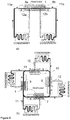
- a heat loop consists of five major elements: evaporator, reservoir, condenser, liquid transport line and vapor transport line ( Figure 1 ).
- Transport lines and condenser are generally a small inner diameter (1-8mm) simple metallic tubing.
- Typical reservoir design is cylindrical volume which can be directly attached to the evaporator (most common heat loop architecture, named in technical literature loop heat pipe, Figure 1a ) or the reservoir can be distantly separated from the evaporator and located along the liquid transport line (Less popular design, named capillary pumped loop, Figure 1b ).
- Evaporator 1 is the principal and the most complex element of the heat loop. It has two functions: to absorb the waste heat by liquid-to-vapor transition (evaporation) and to supply the liquid from a condenser (not shown) (pumping).
- the heat source often has flat geometry (for instance, side of an electronic box, a printed circuit board, chip, etc.). Since the heat loop works on a working fluid saturation line, the internal pressure can significantly vary during operation with temperature changes. To withstand high pressures levels, cylindrical geometry is preferable for heat loop elements and is the most typical.
- a saddle 3 is an interface unit between the cylindrical shape evaporator 1 and the flat (or other shaped) heat source (not shown).
- Evaporation process takes place on the outer surface of a primary wick 4 .
- vapor moves through vapor collecting grooves 6 to an evaporator outlet 12 .
- Liquid returned from the condenser enters liquid inlet 11 , moved inside central channel 7 through secondary wick 5 and primary wick 4 to evaporation surface, formed by outer surface of the primary wick 4 .
- Reservoir 9 is necessary to manage liquid volume variations due to operational and ambient temperature changes. If the heat loop is working in unfavorable gravitational conditions (reservoir 9 below evaporator 1 ) a tertiary wick 10 will supply the liquid to the secondary wick 5 and the secondary wick 5 will supply liquid to the primary wick 4 .
- the primary wick 4 has the smallest pore size among the wicks and tertiary wick 10 has the biggest porous size.
- typical overall pressure drop over the loop is in the range of ⁇ 0.1 up to 1-2 bar.
- the porous size (effective diameter of the pores) of the primary wick 4 should be in the range of 1-10 microns.
- the smaller the porous size the higher capillary potential of the wick.
- the decrease of porous size also leads to reducing wick permeability. It means that overall pressure drop in the loop is increasing and more pumping capacity is required from the primary wick 4 .
- certain optimal ratio between wick porous size and permeability values should be found in practical applications.
- Primary wick 4 is usually manufactured from metal particles or fibers by the sintering process. Then it is machined to specified dimensions and inserted into an evaporator case 2 . High and low pressure sides of the primary wick 4 (external vapor surface and internal liquid central channel) should be well separated. The capillary pumping will not work properly if there is any leakage between two sides larger than primary wick 4 porous size. A sealing 8 provides such separation. Sealing can be performed by different techniques: welding, soldering, co-sintering, pressing, etc.
- the evaporator design is asymmetric: liquid inlet 11 and evaporator vapor outlet 12 are placed on opposite sides of the evaporator 1 , each primary and secondary wicks 4,5 have one open and one closed end, the reservoir 9 is attached to one side.
- This design is not flexible. Every heat loop has to be designed for the given thermal task. If the specifications of a new thermal system have different geometry, different distance between heat source and heat sink, or power and conductance requirements, then the design should be started from the beginning and generally a new evaporator should be developed with other capillary pumps (primary, secondary and tertiary wicks), dimensions and geometry of reservoir.
- the type of evaporator described here cannot serve as a universal building block for various applications.
- the modular capillary evaporator design is proposed in order to expand applications of heat loops and overcome current technology limits.
- FIG. 3 illustrates the overall design of the evaporator-reservoir modular unit for heat loops to which the present invention is applied. Separate features of this embodiment are applicable for each of the following embodiments unless otherwise specified.
- a simple unit which consists of one evaporator 1 and two reservoirs 9a, 9b (reservoir-evaporator-reservoir: R-E-R) is shown in Figure 3a .
- Subcooled liquid from a condenser (not shown) enters into a liquid inlet 11 , then flows through a secondary wick 5 to a primary wick 4 . Evaporation takes place on the outer surface of the primary wick 4 . Vapor moves through vapor collecting grooves 6 toward an evaporator outlet 12 .
- the longitudinal vapor collecting grooves 6 are joined together by a circumferential groove 20 arranged between the outer surface of the primary wick 4 and inner surface of the evaporator envelope 2 in the plane of the evaporator outlet 12 . At least one vapor collecting groove 6 has to be machined on the outer surface of the primary wick 4 or/and on the inner surface of evaporator envelope 2 .
- the connecting circumferential groove 20 is necessary if there are more than one longitudinal vapor collecting grooves 6 , if evaporator outlet 12 is not on the same line with vapor collecting groove 6 or if there are more than one evaporator outlet 12 .
- the evaporator outlet 12 can be positioned in any place of the outer surface of the evaporator envelope 2: inside or outside of an evaporator saddle 3 zone. This position is usually defined by customer specification. However, the preferable position is in the middle of the evaporator 1 as it is shown in Figure 3a . In this case, the vapor pressure drop in the vapor collecting groove(s) 6 has the lowest value since the vapor passing distance before entering into the evaporator outlet 12 is the shortest.
- the evaporator-reservoir modular unit design has at least two sealings 8 which are assigned on two cap ends of every primary wick 4 , covering thereby at least part of end surface of the primary wick 4 .
- the heat loop has one condenser (not shown), all side evaporator outlets 12 of several evaporators 1 should be joined together by a common manifold line 14 which is connected to the condenser.
- the example is a linear design of the evaporator-reservoir modular unit with two evaporators 1 and two reservoirs 9a, 9b, which is illustrated by Figure 3b .
- the secondary wick 5 can be manufactured by the same manner as the primary wick 4 : by sintering from metal powder or fiber.
- the secondary wick 5 is not flexible and the evaporator-reservoir modular unit has a linear configuration: All evaporators 1 and reservoirs 9 are put on the same straight secondary wick 5 , side by side wherein the two next surfaces of two primary wicks 4 contact each other via the sealings 8 and two opposite surfaces of the primary wicks 4 each contact the corresponding reservoir 9a, 9b via the sealings 8 .
- All reservoirs and evaporators of a modular unit have to be hermetically joined (for instance by welding brazing or soldering).
- the configuration of the evaporator-reservoir modular unit includes a highly thermally conductive (for instance, metallic) bayonet tube 30 placed into the central liquid channel 7 .
- a highly thermally conductive (for instance, metallic) bayonet tube 30 placed into the central liquid channel 7 .
- This design permits to cool down fluid, which is accumulated in the end-capping reservoirs 9a and 9b by the subcooled liquid returned from the condenser before the liquid arrives to primary wick 4 .
- the cooling effect of liquid in the chambers is achieved by conductive heat exchange through the bayonet tube wall. This helps to avoid intense boiling on the inner part of the primary wick 4 and to achieve better functional stability and overall performances of the heat loop.
- the bayonet tube 30 can have lateral apertures (not shown).
- the cooling can be additionally intensified by the convection heat transfer in the reservoirs 9a and 9b .
- the evaporator outlets 12 connect vapor collecting groove(s) 6 of each primary wick 4 with the common manifold 14 being connected to the condenser.
- the secondary wick 5 is made from wires of fibers, it is possible to perform bends between multiple evaporators/reservoirs of the modular unit as it is shown in a further particular embodiment, in Figure 3c .
- the secondary wick 5 is manufactured in the shape of rolled metallic or non-metallic woven-wire mesh or in the shape of braided sleeving. This flexible design allows to perform different angle 2- and 3-dimensional bends between evaporators 1 or/and reservoirs 9a, b of the modular unit.
- the straight flexible secondary wick 5 should be inserted into reservoir(s) 9 , fluid-tight coupling element(s) 15 and the central hole(s) 13 of primary wick(s) 4 and then, bending of coupling element(s) 15 with internal flexible secondary wick 5 should be performed.
- three primary wicks 4 each inside of evaporator 1 , are serially connected to each other by means of a common secondary wick 5 , wherein outer end surfaces of two last primary wicks 4 are connected to an own reservoir 9a, 9b , one of which, namely the first reservoir 9a is connected to a condenser via a liquid inlet 11 and the other one, the second reservoir 9b , is blank flanged.
- the secondary wick 5 can also have a composite design: The internal part in the evaporator 1 and the reservoir 9 is inflexible (for instance, sintered), but it is attached (by co-sintering, welding, brazing etc.) to flexible portions located inside of the coupling elements 15 .
- the coupling element 15 designs It can be rigid (bended metallic tube) and flexible (metallic bellows) as it is demonstrated in Figure 3c .
- all coupling elements 15 can be rigid or flexible (not shown).
- FIG. 1 Three evaporator outlets 12a, b, c are connected together via the common manifold 14 to the condenser (not shown). Vapor outlets 12a and 12b are in the central part of the primary wicks 4 (and, consequently, in the middle of the saddles 3 ), but outlet 12c is located outside of the saddle 3 , on the right side of the primary wick 4 .
- Figure 3c also illustrates possible alternatives in the evaporator outlet 12 positioning on the side of the evaporator envelope 2 as it was discussed above. It gives added advantage (better design flexibility) to the evaporator-reservoir modular unit thermal architecture against present-day evaporator thermal systems because the evaporator outlet 12 can be mounted in any point along the evaporator 1 .
- Figure 4 shows the possible linear evaporator-reservoir modular unit arrangements for one evaporator E ( Figure 4b ), two evaporators E ( Figure 4a, c, d, e ), and three-evaporators E ( Figure 4f-j ).
- Evaporator E in this embodiment corresponds to a separate primary wick 4 settled on a single secondary wick 5 for the whole evaporator-reservoir modular unit in combination with corresponding evaporator outlet 12 .
- the modular units reservoirs R are located alternately with the at least one evaporator E and/or in the ends of the unit.
- FIG. 5 Three curved evaporator-reservoir modular units, in further particular embodiments, are shown in Figure 5 to demonstrate the flexibility of the proposed approach in relation to accommodation on different heat generating elements/surfaces.
- R-E-E-R-E-E-R modular unit with two 90° coupling elements 15 in Figure 5a illustrates a possible U-shape system configuration for large heat generating rectangular areas, wherein two pairs of segmentally connected evaporators E are arranged in the legs of "U", two reservoirs R - at the ends and one reservoir R - at the bottom of the U-shaped portion of the modular unit, wherein the opposed arrangement of the reservoirs 9 allows to operate this unit in any spatial orientation.
- One common manifold 14 joins all four evaporator outlets 12 .
- Figure 5b depicts a curved R-E-E-E-R modular unit with two 180° bends of coupling elements 15 .
- Such an S-shaped arrangement can be used for elongated heat generating surfaces and the design can be customized for specific areas by increasing the number of intermediate evaporators E2 and coupling elements 15 .
- the intermediate second evaporator E2 has two evaporator outlets 12-2 and 12-3 , which are interconnected via circumferential groove 20 (not shown in the figures) of evaporator E2 and connected to the circumferential grooves 20 (not shown in the figures) in the plane of the evaporator outlets of evaporators E1 and E3 correspondingly.
- Evaporator outlet 12-1 connects the first evaporator E1 with the condenser. It allows to avoid tee-type connections in the heat loop and complex vapor line manifold routing.
- Modular square-shaped looped unit R-E-R-E-R-E-R-E-R-E with four 90° bends ( Figure 5c ) has a single closed secondary wick 5 , wherein evaporator outlets 12 of each evaporator E are joined by common manifold 14 .
- every evaporator E can be connected to one side of the cooled electronic box (not shown).
- Figure 6 demonstrates another advantage of the invention: The possibility to develop multi-evaporator, multi-condenser heat loops based on evaporator-reservoir modular unit technology.
- the linear R-E-E-R modular unit shown in Figure 6a , has two evaporator outlets 12a,b and two liquid inlets 11a,b .
- Two evaporators 1 are joined together at one end, and joined to reservoirs 9a and 9b at another end.
- the individual evaporator outlets 12a and 12b are linked with two independent condensers C1 and C2 . Returned from every condenser C1 and C2 liquid is entering the separate liquid inlets 11a , b which are located on the end caps of two opposite reservoirs 9a, b .
- the configuration of a curved four-sided modular unit in Figure 6b is presented, which is similar to the unit in Figure 5c but instead of common manifold 14 it has multiple liquid outlets 11 .
- the square-shaped unit has four linear single reservoir R - evaporator E modules which are linked to each other by four 90° coupling elements 15 .
- the closed circuit R-E-R-E-R-E-R-E is formed as a result of such arrangement, wherein all reservoirs 9 and evaporators 1 are interconnected via the common central liquid channel 7 located inside of the common closed secondary wick 5 .
- Every evaporator E is connected to the inlet of dedicated condenser C1, C2, C3, C4 and every coupling element 15 (between the adjacent evaporator E and reservoir R ) is connected to the outlet of dedicated condenser C1 , C2, C3, C4 via corresponding liquid outlet 11 .
- This configuration can be used, for instance, for spacecraft electronics thermal control.
- Evaporators E have to be connected to internal panels or to four sides of the electronic box inside a satellite (not shown), and the condensers C have to be connected to four external radiators (not shown), for instance, to East-West-North South panels for a geostationary satellite. This gives the possibility to use efficiently all available external spacecraft surfaces for heat dissipation by means of a single heat loop.
- liquid inlet 11 can be located on any of three basic components of the modular unit: on the end cap of the reservoir 9 (see, for instance Figures 3a,b,c , 4b ), on the end cap of evaporator 1 ( Figure 4a ) or on the side of coupling element 15 ( Figure 6b ).
- the evaporator outlet 12 can be placed only on the outer side surface of the evaporator 1 .
- Active control of the evaporator-reservoir modular unit heat loop operating temperature can be achieved by installing the heater on any one of the reservoirs R in the unit.
- the controlled reservoir R will always have two phases (vapor and liquid) inside during temperature regulation but other reservoirs R can be totally filled by liquid phase.
- the temperature of this reservoir R will drive the pressure inside of the heat loop and, consequently, temperatures of all evaporators E in the unit. Large heat dissipating areas can be thermally controlled by this method.
Landscapes
- Engineering & Computer Science (AREA)
- Life Sciences & Earth Sciences (AREA)
- Sustainable Development (AREA)
- Physics & Mathematics (AREA)
- Thermal Sciences (AREA)
- Mechanical Engineering (AREA)
- General Engineering & Computer Science (AREA)
- Cooling Or The Like Of Semiconductors Or Solid State Devices (AREA)
- Cooling Or The Like Of Electrical Apparatus (AREA)
Priority Applications (1)
| Application Number | Priority Date | Filing Date | Title |
|---|---|---|---|
| EP17160723.7A EP3376148B1 (de) | 2017-03-14 | 2017-03-14 | Modulare verdampferreservoireinheit |
Applications Claiming Priority (1)
| Application Number | Priority Date | Filing Date | Title |
|---|---|---|---|
| EP17160723.7A EP3376148B1 (de) | 2017-03-14 | 2017-03-14 | Modulare verdampferreservoireinheit |
Publications (2)
| Publication Number | Publication Date |
|---|---|
| EP3376148A1 true EP3376148A1 (de) | 2018-09-19 |
| EP3376148B1 EP3376148B1 (de) | 2019-09-11 |
Family
ID=58347104
Family Applications (1)
| Application Number | Title | Priority Date | Filing Date |
|---|---|---|---|
| EP17160723.7A Active EP3376148B1 (de) | 2017-03-14 | 2017-03-14 | Modulare verdampferreservoireinheit |
Country Status (1)
| Country | Link |
|---|---|
| EP (1) | EP3376148B1 (de) |
Cited By (6)
| Publication number | Priority date | Publication date | Assignee | Title |
|---|---|---|---|---|
| CN110030860A (zh) * | 2019-05-15 | 2019-07-19 | 北京航空航天大学 | 一种双引管型双储液器环路热管 |
| JP2021188760A (ja) * | 2020-05-26 | 2021-12-13 | 新光電気工業株式会社 | ループ型ヒートパイプ |
| CN114646234A (zh) * | 2022-03-23 | 2022-06-21 | 北京航空航天大学 | 一种顺次冷却型双储液器环路热管 |
| JP2023087411A (ja) * | 2021-12-13 | 2023-06-23 | 株式会社村田製作所 | ループヒートパイプ用の蒸発器及びループヒートパイプ |
| IT202200003092A1 (it) * | 2022-02-18 | 2023-08-18 | Thales Alenia Space Italia Spa Con Unico Socio | Gruppo evaporatore modulare per un sistema di controllo termico a tubo di calore ad anello chiuso |
| CN119022695A (zh) * | 2024-10-29 | 2024-11-26 | 中国科学院上海技术物理研究所 | 一种环路热管蒸发器装置及环路热管系统 |
Citations (5)
| Publication number | Priority date | Publication date | Assignee | Title |
|---|---|---|---|---|
| US6330907B1 (en) * | 1997-03-07 | 2001-12-18 | Mitsubishi Denki Kabushiki Kaisha | Evaporator and loop-type heat pipe using the same |
| WO2002002201A2 (en) * | 2000-06-30 | 2002-01-10 | Swales Aerospace | Phase control in the capillary evaporators |
| JP2014114962A (ja) * | 2012-12-06 | 2014-06-26 | Mitsubishi Electric Corp | 宇宙用ループ形ヒートパイプ |
| EP2940416A1 (de) * | 2012-12-28 | 2015-11-04 | Ibérica del Espacio, S.A. | Schlaufenwärmerohrvorrichtung zur wärmeübertragung und wärmeregelung |
| EP2985556A1 (de) * | 2014-08-14 | 2016-02-17 | Ibérica del Espacio, S.A. | Erweiterte zweiphasige Steuerungswärmeübertragungsschleife |
-
2017
- 2017-03-14 EP EP17160723.7A patent/EP3376148B1/de active Active
Patent Citations (5)
| Publication number | Priority date | Publication date | Assignee | Title |
|---|---|---|---|---|
| US6330907B1 (en) * | 1997-03-07 | 2001-12-18 | Mitsubishi Denki Kabushiki Kaisha | Evaporator and loop-type heat pipe using the same |
| WO2002002201A2 (en) * | 2000-06-30 | 2002-01-10 | Swales Aerospace | Phase control in the capillary evaporators |
| JP2014114962A (ja) * | 2012-12-06 | 2014-06-26 | Mitsubishi Electric Corp | 宇宙用ループ形ヒートパイプ |
| EP2940416A1 (de) * | 2012-12-28 | 2015-11-04 | Ibérica del Espacio, S.A. | Schlaufenwärmerohrvorrichtung zur wärmeübertragung und wärmeregelung |
| EP2985556A1 (de) * | 2014-08-14 | 2016-02-17 | Ibérica del Espacio, S.A. | Erweiterte zweiphasige Steuerungswärmeübertragungsschleife |
Cited By (9)
| Publication number | Priority date | Publication date | Assignee | Title |
|---|---|---|---|---|
| CN110030860A (zh) * | 2019-05-15 | 2019-07-19 | 北京航空航天大学 | 一种双引管型双储液器环路热管 |
| JP2021188760A (ja) * | 2020-05-26 | 2021-12-13 | 新光電気工業株式会社 | ループ型ヒートパイプ |
| JP7336416B2 (ja) | 2020-05-26 | 2023-08-31 | 新光電気工業株式会社 | ループ型ヒートパイプ |
| JP2023087411A (ja) * | 2021-12-13 | 2023-06-23 | 株式会社村田製作所 | ループヒートパイプ用の蒸発器及びループヒートパイプ |
| IT202200003092A1 (it) * | 2022-02-18 | 2023-08-18 | Thales Alenia Space Italia Spa Con Unico Socio | Gruppo evaporatore modulare per un sistema di controllo termico a tubo di calore ad anello chiuso |
| WO2023156976A1 (en) * | 2022-02-18 | 2023-08-24 | Thales Alenia Space Italia S.P.A. Con Unico Socio | Modular evaporator assembly for a loop heat pipe thermal control system |
| US20250164194A1 (en) * | 2022-02-18 | 2025-05-22 | Thales Alenia Space Italia S.P.A. Con Unico Socio | Modular Evaporator Assembly for a Loop Heat Pipe Thermal Control System |
| CN114646234A (zh) * | 2022-03-23 | 2022-06-21 | 北京航空航天大学 | 一种顺次冷却型双储液器环路热管 |
| CN119022695A (zh) * | 2024-10-29 | 2024-11-26 | 中国科学院上海技术物理研究所 | 一种环路热管蒸发器装置及环路热管系统 |
Also Published As
| Publication number | Publication date |
|---|---|
| EP3376148B1 (de) | 2019-09-11 |
Similar Documents
| Publication | Publication Date | Title |
|---|---|---|
| EP3376148B1 (de) | Modulare verdampferreservoireinheit | |
| US10259064B2 (en) | Methods of forming a thermal storage unit | |
| US8272233B2 (en) | Heat exchanger and refrigerating air conditioner | |
| US9200852B2 (en) | Evaporator including a wick for use in a two-phase heat transfer system | |
| EP2241849B1 (de) | Mikrokanalwärmetauscher nach Rohr-Rippen-Block Bauart mit besonderer Führung des Rücklaufrohres | |
| CN102245995B (zh) | 具有相互连通的毛细热管网络的热控器件 | |
| US4770238A (en) | Capillary heat transport and fluid management device | |
| US20170094843A1 (en) | Cooling device and method for cooling at least two power electronic devices | |
| KR20170005164A (ko) | 마이크로스케일 열 또는 열 및 물질 전달 시스템 | |
| EP3186574B1 (de) | Thermosiphon mit integrierten komponenten | |
| KR20150060780A (ko) | 응축기 | |
| EP3141859B1 (de) | Mikrokanalwärmetauscher | |
| EP3473963A1 (de) | Wärmetauscher und klimaanlage | |
| US7661464B2 (en) | Evaporator for use in a heat transfer system | |
| ES2453904T3 (es) | Sistema de transferencia de calor | |
| CN112584671A (zh) | 用于冷却电子构件的均温板 | |
| EP1682309B1 (de) | Herstellung eines verdampfers für ein wärmeübertragungssystem | |
| KR100995419B1 (ko) | 평판형 양면 증발면을 가지는 루프 히트 파이프 장치의 증발기 | |
| KR102749268B1 (ko) | 열교환기 및 냉동 사이클 장치 | |
| EP4479699B1 (de) | Modulare verdampferanordnung für ein kreislaufwärmerohrwärmesteuerungssystem | |
| KR101336346B1 (ko) | 냉매 시스템 | |
| EP3086074A1 (de) | Rohrelement und wärmetauscher | |
| KR101357938B1 (ko) | 냉매 시스템 | |
| KR20240075169A (ko) | 우주장치 냉각용 진동형 히트파이프 | |
| KR20190142855A (ko) | 응축기 |
Legal Events
| Date | Code | Title | Description |
|---|---|---|---|
| PUAI | Public reference made under article 153(3) epc to a published international application that has entered the european phase |
Free format text: ORIGINAL CODE: 0009012 |
|
| STAA | Information on the status of an ep patent application or granted ep patent |
Free format text: STATUS: REQUEST FOR EXAMINATION WAS MADE |
|
| 17P | Request for examination filed |
Effective date: 20180404 |
|
| AK | Designated contracting states |
Kind code of ref document: A1 Designated state(s): AL AT BE BG CH CY CZ DE DK EE ES FI FR GB GR HR HU IE IS IT LI LT LU LV MC MK MT NL NO PL PT RO RS SE SI SK SM TR |
|
| AX | Request for extension of the european patent |
Extension state: BA ME |
|
| GRAP | Despatch of communication of intention to grant a patent |
Free format text: ORIGINAL CODE: EPIDOSNIGR1 |
|
| STAA | Information on the status of an ep patent application or granted ep patent |
Free format text: STATUS: GRANT OF PATENT IS INTENDED |
|
| RIC1 | Information provided on ipc code assigned before grant |
Ipc: F28D 15/04 20060101AFI20190409BHEP Ipc: F28D 15/02 20060101ALN20190409BHEP |
|
| INTG | Intention to grant announced |
Effective date: 20190430 |
|
| GRAS | Grant fee paid |
Free format text: ORIGINAL CODE: EPIDOSNIGR3 |
|
| GRAA | (expected) grant |
Free format text: ORIGINAL CODE: 0009210 |
|
| STAA | Information on the status of an ep patent application or granted ep patent |
Free format text: STATUS: THE PATENT HAS BEEN GRANTED |
|
| AK | Designated contracting states |
Kind code of ref document: B1 Designated state(s): AL AT BE BG CH CY CZ DE DK EE ES FI FR GB GR HR HU IE IS IT LI LT LU LV MC MK MT NL NO PL PT RO RS SE SI SK SM TR |
|
| REG | Reference to a national code |
Ref country code: GB Ref legal event code: FG4D |
|
| REG | Reference to a national code |
Ref country code: CH Ref legal event code: EP |
|
| REG | Reference to a national code |
Ref country code: AT Ref legal event code: REF Ref document number: 1178981 Country of ref document: AT Kind code of ref document: T Effective date: 20190915 |
|
| REG | Reference to a national code |
Ref country code: DE Ref legal event code: R096 Ref document number: 602017006844 Country of ref document: DE Ref country code: IE Ref legal event code: FG4D |
|
| REG | Reference to a national code |
Ref country code: NL Ref legal event code: MP Effective date: 20190911 |
|
| REG | Reference to a national code |
Ref country code: LT Ref legal event code: MG4D |
|
| PG25 | Lapsed in a contracting state [announced via postgrant information from national office to epo] |
Ref country code: BG Free format text: LAPSE BECAUSE OF FAILURE TO SUBMIT A TRANSLATION OF THE DESCRIPTION OR TO PAY THE FEE WITHIN THE PRESCRIBED TIME-LIMIT Effective date: 20191211 Ref country code: NO Free format text: LAPSE BECAUSE OF FAILURE TO SUBMIT A TRANSLATION OF THE DESCRIPTION OR TO PAY THE FEE WITHIN THE PRESCRIBED TIME-LIMIT Effective date: 20191211 Ref country code: SE Free format text: LAPSE BECAUSE OF FAILURE TO SUBMIT A TRANSLATION OF THE DESCRIPTION OR TO PAY THE FEE WITHIN THE PRESCRIBED TIME-LIMIT Effective date: 20190911 Ref country code: HR Free format text: LAPSE BECAUSE OF FAILURE TO SUBMIT A TRANSLATION OF THE DESCRIPTION OR TO PAY THE FEE WITHIN THE PRESCRIBED TIME-LIMIT Effective date: 20190911 Ref country code: LT Free format text: LAPSE BECAUSE OF FAILURE TO SUBMIT A TRANSLATION OF THE DESCRIPTION OR TO PAY THE FEE WITHIN THE PRESCRIBED TIME-LIMIT Effective date: 20190911 Ref country code: FI Free format text: LAPSE BECAUSE OF FAILURE TO SUBMIT A TRANSLATION OF THE DESCRIPTION OR TO PAY THE FEE WITHIN THE PRESCRIBED TIME-LIMIT Effective date: 20190911 |
|
| PG25 | Lapsed in a contracting state [announced via postgrant information from national office to epo] |
Ref country code: LV Free format text: LAPSE BECAUSE OF FAILURE TO SUBMIT A TRANSLATION OF THE DESCRIPTION OR TO PAY THE FEE WITHIN THE PRESCRIBED TIME-LIMIT Effective date: 20190911 Ref country code: ES Free format text: LAPSE BECAUSE OF FAILURE TO SUBMIT A TRANSLATION OF THE DESCRIPTION OR TO PAY THE FEE WITHIN THE PRESCRIBED TIME-LIMIT Effective date: 20190911 Ref country code: RS Free format text: LAPSE BECAUSE OF FAILURE TO SUBMIT A TRANSLATION OF THE DESCRIPTION OR TO PAY THE FEE WITHIN THE PRESCRIBED TIME-LIMIT Effective date: 20190911 Ref country code: GR Free format text: LAPSE BECAUSE OF FAILURE TO SUBMIT A TRANSLATION OF THE DESCRIPTION OR TO PAY THE FEE WITHIN THE PRESCRIBED TIME-LIMIT Effective date: 20191212 Ref country code: AL Free format text: LAPSE BECAUSE OF FAILURE TO SUBMIT A TRANSLATION OF THE DESCRIPTION OR TO PAY THE FEE WITHIN THE PRESCRIBED TIME-LIMIT Effective date: 20190911 |
|
| REG | Reference to a national code |
Ref country code: AT Ref legal event code: MK05 Ref document number: 1178981 Country of ref document: AT Kind code of ref document: T Effective date: 20190911 |
|
| PG25 | Lapsed in a contracting state [announced via postgrant information from national office to epo] |
Ref country code: NL Free format text: LAPSE BECAUSE OF FAILURE TO SUBMIT A TRANSLATION OF THE DESCRIPTION OR TO PAY THE FEE WITHIN THE PRESCRIBED TIME-LIMIT Effective date: 20190911 Ref country code: EE Free format text: LAPSE BECAUSE OF FAILURE TO SUBMIT A TRANSLATION OF THE DESCRIPTION OR TO PAY THE FEE WITHIN THE PRESCRIBED TIME-LIMIT Effective date: 20190911 Ref country code: AT Free format text: LAPSE BECAUSE OF FAILURE TO SUBMIT A TRANSLATION OF THE DESCRIPTION OR TO PAY THE FEE WITHIN THE PRESCRIBED TIME-LIMIT Effective date: 20190911 Ref country code: IT Free format text: LAPSE BECAUSE OF FAILURE TO SUBMIT A TRANSLATION OF THE DESCRIPTION OR TO PAY THE FEE WITHIN THE PRESCRIBED TIME-LIMIT Effective date: 20190911 Ref country code: RO Free format text: LAPSE BECAUSE OF FAILURE TO SUBMIT A TRANSLATION OF THE DESCRIPTION OR TO PAY THE FEE WITHIN THE PRESCRIBED TIME-LIMIT Effective date: 20190911 Ref country code: PT Free format text: LAPSE BECAUSE OF FAILURE TO SUBMIT A TRANSLATION OF THE DESCRIPTION OR TO PAY THE FEE WITHIN THE PRESCRIBED TIME-LIMIT Effective date: 20200113 Ref country code: PL Free format text: LAPSE BECAUSE OF FAILURE TO SUBMIT A TRANSLATION OF THE DESCRIPTION OR TO PAY THE FEE WITHIN THE PRESCRIBED TIME-LIMIT Effective date: 20190911 |
|
| PG25 | Lapsed in a contracting state [announced via postgrant information from national office to epo] |
Ref country code: IS Free format text: LAPSE BECAUSE OF FAILURE TO SUBMIT A TRANSLATION OF THE DESCRIPTION OR TO PAY THE FEE WITHIN THE PRESCRIBED TIME-LIMIT Effective date: 20200224 Ref country code: SK Free format text: LAPSE BECAUSE OF FAILURE TO SUBMIT A TRANSLATION OF THE DESCRIPTION OR TO PAY THE FEE WITHIN THE PRESCRIBED TIME-LIMIT Effective date: 20190911 Ref country code: CZ Free format text: LAPSE BECAUSE OF FAILURE TO SUBMIT A TRANSLATION OF THE DESCRIPTION OR TO PAY THE FEE WITHIN THE PRESCRIBED TIME-LIMIT Effective date: 20190911 Ref country code: SM Free format text: LAPSE BECAUSE OF FAILURE TO SUBMIT A TRANSLATION OF THE DESCRIPTION OR TO PAY THE FEE WITHIN THE PRESCRIBED TIME-LIMIT Effective date: 20190911 |
|
| REG | Reference to a national code |
Ref country code: DE Ref legal event code: R097 Ref document number: 602017006844 Country of ref document: DE |
|
| PLBE | No opposition filed within time limit |
Free format text: ORIGINAL CODE: 0009261 |
|
| STAA | Information on the status of an ep patent application or granted ep patent |
Free format text: STATUS: NO OPPOSITION FILED WITHIN TIME LIMIT |
|
| PG2D | Information on lapse in contracting state deleted |
Ref country code: IS |
|
| PG25 | Lapsed in a contracting state [announced via postgrant information from national office to epo] |
Ref country code: DK Free format text: LAPSE BECAUSE OF FAILURE TO SUBMIT A TRANSLATION OF THE DESCRIPTION OR TO PAY THE FEE WITHIN THE PRESCRIBED TIME-LIMIT Effective date: 20190911 Ref country code: IS Free format text: LAPSE BECAUSE OF FAILURE TO SUBMIT A TRANSLATION OF THE DESCRIPTION OR TO PAY THE FEE WITHIN THE PRESCRIBED TIME-LIMIT Effective date: 20200112 |
|
| 26N | No opposition filed |
Effective date: 20200615 |
|
| PG25 | Lapsed in a contracting state [announced via postgrant information from national office to epo] |
Ref country code: SI Free format text: LAPSE BECAUSE OF FAILURE TO SUBMIT A TRANSLATION OF THE DESCRIPTION OR TO PAY THE FEE WITHIN THE PRESCRIBED TIME-LIMIT Effective date: 20190911 |
|
| REG | Reference to a national code |
Ref country code: DE Ref legal event code: R119 Ref document number: 602017006844 Country of ref document: DE |
|
| PG25 | Lapsed in a contracting state [announced via postgrant information from national office to epo] |
Ref country code: MC Free format text: LAPSE BECAUSE OF FAILURE TO SUBMIT A TRANSLATION OF THE DESCRIPTION OR TO PAY THE FEE WITHIN THE PRESCRIBED TIME-LIMIT Effective date: 20190911 |
|
| REG | Reference to a national code |
Ref country code: CH Ref legal event code: PL |
|
| REG | Reference to a national code |
Ref country code: BE Ref legal event code: MM Effective date: 20200331 |
|
| PG25 | Lapsed in a contracting state [announced via postgrant information from national office to epo] |
Ref country code: LU Free format text: LAPSE BECAUSE OF NON-PAYMENT OF DUE FEES Effective date: 20200314 |
|
| PG25 | Lapsed in a contracting state [announced via postgrant information from national office to epo] |
Ref country code: FR Free format text: LAPSE BECAUSE OF NON-PAYMENT OF DUE FEES Effective date: 20200331 Ref country code: DE Free format text: LAPSE BECAUSE OF NON-PAYMENT OF DUE FEES Effective date: 20201001 Ref country code: CH Free format text: LAPSE BECAUSE OF NON-PAYMENT OF DUE FEES Effective date: 20200331 Ref country code: IE Free format text: LAPSE BECAUSE OF NON-PAYMENT OF DUE FEES Effective date: 20200314 Ref country code: LI Free format text: LAPSE BECAUSE OF NON-PAYMENT OF DUE FEES Effective date: 20200331 |
|
| PG25 | Lapsed in a contracting state [announced via postgrant information from national office to epo] |
Ref country code: BE Free format text: LAPSE BECAUSE OF NON-PAYMENT OF DUE FEES Effective date: 20200331 |
|
| GBPC | Gb: european patent ceased through non-payment of renewal fee |
Effective date: 20210314 |
|
| PG25 | Lapsed in a contracting state [announced via postgrant information from national office to epo] |
Ref country code: GB Free format text: LAPSE BECAUSE OF NON-PAYMENT OF DUE FEES Effective date: 20210314 |
|
| PG25 | Lapsed in a contracting state [announced via postgrant information from national office to epo] |
Ref country code: TR Free format text: LAPSE BECAUSE OF FAILURE TO SUBMIT A TRANSLATION OF THE DESCRIPTION OR TO PAY THE FEE WITHIN THE PRESCRIBED TIME-LIMIT Effective date: 20190911 Ref country code: MT Free format text: LAPSE BECAUSE OF FAILURE TO SUBMIT A TRANSLATION OF THE DESCRIPTION OR TO PAY THE FEE WITHIN THE PRESCRIBED TIME-LIMIT Effective date: 20190911 Ref country code: CY Free format text: LAPSE BECAUSE OF FAILURE TO SUBMIT A TRANSLATION OF THE DESCRIPTION OR TO PAY THE FEE WITHIN THE PRESCRIBED TIME-LIMIT Effective date: 20190911 |
|
| PG25 | Lapsed in a contracting state [announced via postgrant information from national office to epo] |
Ref country code: MK Free format text: LAPSE BECAUSE OF FAILURE TO SUBMIT A TRANSLATION OF THE DESCRIPTION OR TO PAY THE FEE WITHIN THE PRESCRIBED TIME-LIMIT Effective date: 20190911 |