EP3382103A2 - Raccord rapide - Google Patents
Raccord rapide Download PDFInfo
- Publication number
- EP3382103A2 EP3382103A2 EP18160660.9A EP18160660A EP3382103A2 EP 3382103 A2 EP3382103 A2 EP 3382103A2 EP 18160660 A EP18160660 A EP 18160660A EP 3382103 A2 EP3382103 A2 EP 3382103A2
- Authority
- EP
- European Patent Office
- Prior art keywords
- locking
- coupler
- drive shaft
- coupler body
- recess
- Prior art date
- Legal status (The legal status is an assumption and is not a legal conclusion. Google has not performed a legal analysis and makes no representation as to the accuracy of the status listed.)
- Granted
Links
Images


Classifications
-
- E—FIXED CONSTRUCTIONS
- E02—HYDRAULIC ENGINEERING; FOUNDATIONS; SOIL SHIFTING
- E02F—DREDGING; SOIL-SHIFTING
- E02F3/00—Dredgers; Soil-shifting machines
- E02F3/04—Dredgers; Soil-shifting machines mechanically-driven
- E02F3/28—Dredgers; Soil-shifting machines mechanically-driven with digging tools mounted on a dipper- or bucket-arm, i.e. there is either one arm or a pair of arms, e.g. dippers, buckets
- E02F3/36—Component parts
- E02F3/3604—Devices to connect tools to arms, booms or the like
- E02F3/3609—Devices to connect tools to arms, booms or the like of the quick acting type, e.g. controlled from the operator seat
- E02F3/3672—Devices to connect tools to arms, booms or the like of the quick acting type, e.g. controlled from the operator seat where disengagement is effected by a mechanical lever or handle
-
- E—FIXED CONSTRUCTIONS
- E02—HYDRAULIC ENGINEERING; FOUNDATIONS; SOIL SHIFTING
- E02F—DREDGING; SOIL-SHIFTING
- E02F3/00—Dredgers; Soil-shifting machines
- E02F3/04—Dredgers; Soil-shifting machines mechanically-driven
- E02F3/28—Dredgers; Soil-shifting machines mechanically-driven with digging tools mounted on a dipper- or bucket-arm, i.e. there is either one arm or a pair of arms, e.g. dippers, buckets
- E02F3/36—Component parts
- E02F3/3604—Devices to connect tools to arms, booms or the like
- E02F3/3609—Devices to connect tools to arms, booms or the like of the quick acting type, e.g. controlled from the operator seat
- E02F3/3613—Devices to connect tools to arms, booms or the like of the quick acting type, e.g. controlled from the operator seat with means for absorbing any play therebetween
-
- E—FIXED CONSTRUCTIONS
- E02—HYDRAULIC ENGINEERING; FOUNDATIONS; SOIL SHIFTING
- E02F—DREDGING; SOIL-SHIFTING
- E02F3/00—Dredgers; Soil-shifting machines
- E02F3/04—Dredgers; Soil-shifting machines mechanically-driven
- E02F3/28—Dredgers; Soil-shifting machines mechanically-driven with digging tools mounted on a dipper- or bucket-arm, i.e. there is either one arm or a pair of arms, e.g. dippers, buckets
- E02F3/36—Component parts
- E02F3/3604—Devices to connect tools to arms, booms or the like
- E02F3/3609—Devices to connect tools to arms, booms or the like of the quick acting type, e.g. controlled from the operator seat
- E02F3/3622—Devices to connect tools to arms, booms or the like of the quick acting type, e.g. controlled from the operator seat with a hook and a locking element acting on a pin
-
- E—FIXED CONSTRUCTIONS
- E02—HYDRAULIC ENGINEERING; FOUNDATIONS; SOIL SHIFTING
- E02F—DREDGING; SOIL-SHIFTING
- E02F3/00—Dredgers; Soil-shifting machines
- E02F3/04—Dredgers; Soil-shifting machines mechanically-driven
- E02F3/28—Dredgers; Soil-shifting machines mechanically-driven with digging tools mounted on a dipper- or bucket-arm, i.e. there is either one arm or a pair of arms, e.g. dippers, buckets
- E02F3/36—Component parts
- E02F3/3604—Devices to connect tools to arms, booms or the like
- E02F3/3609—Devices to connect tools to arms, booms or the like of the quick acting type, e.g. controlled from the operator seat
- E02F3/364—Devices to connect tools to arms, booms or the like of the quick acting type, e.g. controlled from the operator seat using wedges
-
- E—FIXED CONSTRUCTIONS
- E02—HYDRAULIC ENGINEERING; FOUNDATIONS; SOIL SHIFTING
- E02F—DREDGING; SOIL-SHIFTING
- E02F3/00—Dredgers; Soil-shifting machines
- E02F3/04—Dredgers; Soil-shifting machines mechanically-driven
- E02F3/28—Dredgers; Soil-shifting machines mechanically-driven with digging tools mounted on a dipper- or bucket-arm, i.e. there is either one arm or a pair of arms, e.g. dippers, buckets
- E02F3/36—Component parts
- E02F3/3604—Devices to connect tools to arms, booms or the like
- E02F3/3609—Devices to connect tools to arms, booms or the like of the quick acting type, e.g. controlled from the operator seat
- E02F3/3654—Devices to connect tools to arms, booms or the like of the quick acting type, e.g. controlled from the operator seat with energy coupler, e.g. coupler for hydraulic or electric lines, to provide energy to drive(s) mounted on the tool
-
- E—FIXED CONSTRUCTIONS
- E02—HYDRAULIC ENGINEERING; FOUNDATIONS; SOIL SHIFTING
- E02F—DREDGING; SOIL-SHIFTING
- E02F3/00—Dredgers; Soil-shifting machines
- E02F3/04—Dredgers; Soil-shifting machines mechanically-driven
- E02F3/28—Dredgers; Soil-shifting machines mechanically-driven with digging tools mounted on a dipper- or bucket-arm, i.e. there is either one arm or a pair of arms, e.g. dippers, buckets
- E02F3/36—Component parts
- E02F3/3604—Devices to connect tools to arms, booms or the like
- E02F3/3609—Devices to connect tools to arms, booms or the like of the quick acting type, e.g. controlled from the operator seat
- E02F3/3668—Devices to connect tools to arms, booms or the like of the quick acting type, e.g. controlled from the operator seat where engagement is effected by a mechanical lever or handle
Definitions
- the present invention relates to a quick coupler for coupling a tool such as excavator buckets, claw grippers or demolition tongs to a tool guide such as excavator handle or the like, with a coupler body having on opposite ends on the one hand a Ankuppelability for receiving a first locking part of a coupler part to be coupled and on the other hand a locking receptacle for Receiving a second locking part of the coupling part to be coupled, wherein at least the locking receptacle is associated with at least one movable locking part for locking the second locking part, wherein said locking element is manually operable via a arranged on the coupler body actuating mechanism.
- Such quick coupler can have as locking elements in particular two spaced apart locking axes on a coupling part, while the other coupling part, in particular the handlebar side coupling part may have a preferably hook-shaped coupling receptacle for hooking on a first of the two locking axes and a locking receptacle for locking on the second locking axis.
- a third-party actuated actuating actuator is provided, which may be designed, for example, as a hydraulic cylinder and is usually actuatable by hydraulic pressure from the device.
- the said locking axes on the one coupling part can thereby be formed by locking bolts, which may extend in particular parallel to each other on the corresponding coupling part, but instead of such bolts but possibly other structural parts of the coupling part such as projecting lugs, stub axles, engagement stumps in the form of projections or Recesses, for example in the form of pockets can serve as a locking part, which are adapted to the Ankuppelage or the locking receptacle of the other coupling part.
- Such quick couplers are also the subject of standards in terms of dimensions and locking parts, in order to ensure compatibility with the excavator handle used coupler half with various tools on which a coupler half is mounted, which may come from different manufacturers depending on the tool and as far as the stalk coupler half must be compatible so that the two coupler halves can move together and lock.
- standardization is carried out, for example, in the form of the so-called S-coupler or the S-standard, which stipulates the dimensions and arrangement of the locking elements and receiving jaws and was defined by the Swedish Maskinleverantörerna Institute and was last issued on 28.05.2010.
- This S-coupler has in the manner described above on one coupler half two parallel, spaced-apart cross bolt as locking parts, while the other coupler half has on opposite ends on the one hand a muzzle Ankoppelfact and on the other hand, an L-shaped locking receptacle which closed by a pair of extendable locking bolt or to a then also U-shaped or mouth-shaped receptacle can be closed.
- the font shows WO 2016/198638 A1 a quick coupler, in which the locking elements via rotary actuator parts of a drive shaft forth ago and are retractable, wherein to the said drive shaft, a hand tool for manually operating the quick coupler can be connected.
- a hydraulic rotary motor is connected to said drive shaft in order to actuate the drive shaft and thus the locking element also by motor.
- the locking elements are associated with hydraulic actuators, for example in the form of hydraulic cylinders, by means of which the locking elements can be retracted and extended.
- hydraulic actuators for example in the form of hydraulic cylinders, by means of which the locking elements can be retracted and extended.
- the coupler halves also have hydraulic clutches, the automatically collapse when swinging the two coupler halves together.
- Such manually operable quick couplers usually have a control gear which is arranged on the coupler body, on which the said locking elements can be moved in and out or in another way between locking and unlocking position.
- a lever mechanism may be provided which can be actuated by a rotatable rotary actuator, so that a favorable manual operation can be achieved via the lever ratios.
- a wrench or a similar tool as it is known in a comparable form for loosening and tightening the wheel nuts when changing the wheel on a motor vehicle, are releasably attached to said rotary actuator part, for example via a polygonal connector to actuate the rotary actuator.
- Such a control gear expediently also includes a spring that biases the locking element.
- the present invention has the object to provide an improved quick coupler of the type mentioned, which avoids the disadvantages of the prior art and further develops the latter in an advantageous manner.
- a secure and at the same time simple manual locking should be made possible with a compact design, even if the opposite coupler half has hydraulic or other energy-circuit couplings.
- the locking element associated with the locking element and a movable, additional Sich ceremoniesslement that is associated with the Ankuppelfact for securing the first locking member therein actuated by the common drive shaft and each articulated via an actuating link on a rotatably connected to the common drive shaft rotary actuator part, so that the Verriegelungslement and the securing element by rotating the common drive shaft in a rotational direction to each other in opposite directions.
- the locking element moves toward one side of the quick-release body in the locking receptacle provided there, while the fuse element moves towards the opposite side of the coupler body in the Ankuppelfact provided there, when the common drive shaft is rotated in one direction. If the drive shaft is rotated in the opposite direction of rotation, the locking and securing elements move counter to each other in their respective unlocking position.
- said drive shaft may extend transversely across the coupler body between the coupling receptacle and the latch receptacle, in particular in a direction perpendicular to the adjustment directions of the latching and securing elements, wherein a through-passage may advantageously be provided in a side wall of the coupler body through which passes the drive shaft may extend to an outside of the coupler body to be coupled there with a hand tool.
- the hand tool can be inserted through said passage recess to be coupled in said side cheek or within said side cheek to the drive shaft.
- the coupling of the hand tool can basically be done in various ways.
- the hand tool by means of a shaft-hub connection rotatably mounted on the drive shaft, so that the hand tool and the drive shaft extend approximately coaxially to each other.
- the hand tool and the drive shaft but can also be arranged offset from each other, for example by a pinion rotatably on the drive shaft and a pinion rotatably provided on the hand tool and can interlock in the sense of a spur gear.
- a bevel gear stage can also be connected between the hand tool and the drive shaft on the pakker body in order to tilt or bend the axis of rotation of the hand tool relative to the axis of rotation of the drive shaft.
- a reduction or translation between hand tool and Drive shaft can be generated, which allows a particularly power-saving, mecanicgnature operating the quick coupler.
- the additional securing element can be moved into the Ankuppelage obliquely and / or acute-angled to prevent the locking member located there form-fitting on slipping out of the Ankuppelage.
- said coupling receptacle can form a mouth-shaped blind groove with a groove longitudinal axis, which is open to one side of the coupler body, which faces away from the locking receptacle, wherein the Ankuppelage with its said groove longitudinal axis to a control axis of the fuse element and / or to a connection plane , which goes through both the Ankuppelability and through the locking receptacle, can extend at an acute angle inclined.
- said Ankuppelage may, for example, angled at an acute angle obliquely upwards and / or obliquely obliquely downwards inclined, the securing element substantially horizontally moved and can be partially moved into the Ankuppelage inside to block the entry and exit path for the associated locking part.
- the Verriegelungslement can be moved substantially horizontally, when said cuboid coupling body is considered in a horizontal position.
- the locking element and the securing element can both be moved horizontally or along mutually substantially parallel axes, which is favorable for the operation by the common drive shaft and at the same time enables a compact, flat construction of the coupler.
- the rotary adjusting parts on which the locking part on the one hand and the securing element on the other hand are articulated on the already mentioned actuating link, on opposite sides of the Extend drive shaft and be arranged such that the actuating arm of the locking element and the securing element are overstretched during rotation of the drive shaft from the unlocking position to the locking position and each run over a dead center.
- the securing element on the one hand and the locking element on the other hand be connected in different ways to the rotational movement of the common drive shaft, in particular such that the securing element is substantially free of play, forcibly coupled to the rotation of the drive shaft, while the locking element a limited clearance against the rotational movement of the Drive shaft, for example, by providing a longitudinal groove or a slot, which can form a point of articulation of the actuating arm.
- a biasing device for example in the form of a spring device, be assigned to drive the locking element in the contacting, abutting position on the locking part.
- the said clearance is in this case relatively small and in each case so limited that the locking element, even if the clearance is utilized, the lock receptacle blocked sufficiently to prevent falling out of the locking element safely.
- the additional securing element which is associated with the Ankuppelage, positively convert the rotary drive shaft of the drive shaft without clearance implement.
- the fuse element must not be driven to stop, but it may be sufficient to drive the said fuse sufficiently oblique in the Ankuppelage to obstruct the path for the locking part.
- a monitoring device may be provided in the development of the invention, which comprises at least one rotary position sensor for detecting the rotational position of the drive shaft.
- the said rotary position sensor can be designed to detect the achievement of the locking rotational position of the drive shaft in order to be able to deliver a corresponding signal, which indicates the reaching of the locking position.
- the said rotary position sensor does not have to be assigned directly to the drive shaft, but can, for example, also detect the position of one of the rotary actuator parts, which are connected in a rotationally fixed manner to the drive shaft.
- the monitoring device also comprises two pick-up sensors, which are associated with the coupling receptacle on the one hand and the latch receptacle on the other, and respectively monitor the presence of the first latching part and the second latching part in the coupling receptacle or the latch receptacle.
- the coupler body has in a central portion between its provided at opposite ends coupling and locking receptacles to be coupled to the coupling part down recess for receiving and / or retracting hydraulic connections of the coupler part to be coupled, wherein the actuating mechanism for manually actuating the at least one locking member in addition to said Recess, the recess is released.
- the hydraulic connections can retract into said recess between edge arranged Kuppler Modellmaschine and / or Stellgetriebeabête and thus the Kupplerkorpus be driven without collision on the coupler part to be coupled.
- the quick coupler can continue to be used for hydraulic coupler solutions, as in this case said recess in the coupler body simply remains free, if no hydraulic or power circuit couplings are provided on the counterpart.
- Said recess may in this case form a cup-shaped or trough-shaped depression in the underside of the coupler body, ie in the coupler body side which is driven onto the coupling part to be coupled when coupling, wherein said cup-shaped or trough-shaped depression is made sufficiently deep to accommodate the hydraulics - To record or power circuit clutches on the dome part to be coupled.
- the said recess can at the edge of stiffening and / or strength-increasing structure thickening and / or edge beads and / or adjusting gear sections of the manually operable Adjusted or enclosed actuating gear, wherein such structure thickening or edge beads may advantageously be provided on at least two or three edge sides of said recess.
- said structural thickenings or edge thickenings may extend along the side edges of the coupler body, while the central region of the coupler body is recessed from such structural thickenings and / or may be formed by a flat, thin plate or a similarly thin structural sheet or part.
- the aforementioned adjusting gear sections can also be arranged at least partially within said edge-bordering structural thickenings and / or edge beads.
- said central recess may be at least partially formed as a through-hole, so that in the coupler body, a central through-hole is provided with a free visual axis therethrough.
- Said through-passage can pass centrally through the coupler body and extend from the underside of the coupler body, which is intended to be driven onto the counterpart or coupler part to be coupled, up to its upper side.
- the coupler part possibly present on the coupler part which may be present remain accessible even when the coupler is coupled, from above or through the said passage recess.
- the quick coupler regardless of the height of possibly existing hydraulic couplings can be built very flat.
- Said recess in the coupler body may vary in size, wherein it is dimensioned sufficiently large in each case to accommodate the present at the counterpart hydraulic or power circuit clutches.
- said recess can advantageously in the transverse direction - ie transverse to the adjusting axis of the locking element and / or transversely to the plane of the coupling movement and / or parallel to the bolt-shaped locking parts of the coupling part to be coupled - a clear width of more than 50% or more than 66% of the width of the entire coupler body possess.
- the recess can advantageously a clear width or length of at least more than 33% or more than 50% of the spacing of the coupling and locking receptacles, wherein also a length more than 66% of said spacing is possible.
- the actuating mechanism laid next to said recess may, in an advantageous embodiment of the invention, comprise a rotatably mounted rotary actuator which, by turning over an actuating link, displaces the locking element with which the locking receptacle is closed or the locking part received therein is locked.
- a spring device can be coupled with said rotary actuator part, in particular in such a way that upon rotation of the rotary actuator part a dead center is run over and the rotary actuator part can be prestressed by the spring device into opposite end positions which can correspond to the locked and unlocked positions of the coupler.
- the spring device is more relaxed in both end positions of the rotary actuator than in the intermediate dead center position, so that the spring device can hold the actuating gear both in the unlocked position and in the locked position by spring force. In order to move from the unlocked position to the locked position or vice versa from the locked to the unlocked position, manually said spring force must be overcome.
- the said spring means on the one hand and the actuating link on the other hand which converts the rotational movement of the rotary actuator into an actuating movement of the locking element, be arranged on different or opposite sides of the locking part.
- said assembly comprising the rotary actuator, the actuating arm and the spring device can extend laterally along the coupler body and / or along said recess, without the assembly, the recess and the retractability of the hydraulic couplings in the Obstruct or restrict the area of the recess.
- said assembly can be made relatively long or take advantage of a large part of the available length of the coupler body, whereby a favorable leverage and a simple design spring means can be provided.
- the said spring device can advantageously act directly on said rotary actuator part and / or bias a clamping arm, which is hinged on the one hand articulated to said rotary actuator part and on the other hand slidably guided on the Kupplerkorpus.
- the spring means may be associated with said biasing link such that said biasing link is biased along its longitudinal direction and is being urged against the pincer body by the spring force.
- the quick coupler may comprise two locking elements, which are associated with said locking receptacle and can lock a locking member received therein.
- each of said locking elements is a separate Stellgetriebebaueria each comprising a rotary actuator, associated with an articulated actuation link and a spring device, wherein said adjusting gear assemblies advantageously laterally to opposite Can extend edges of the coupler body and / or on opposite sides of the aforementioned recess.
- the two Stellgetriebebau phenomenon can be synchronized by a synchronization shaft, which connects the two Wheelberichtile each other and synchronized in terms of their rotation.
- a rotational synchronization of the two rotary actuator parts and thus the locking movement of the locking elements can also be achieved by the actuation tool to be applied, which can replace or have, for example, said synchronization shaft.
- the hand tool can be inserted from one side into both rotary actuator parts, for example via a polygonal recess and / or a splined recess and / or an otherwise torque-transmitting recess in the two rotary actuator parts.
- the two adjusting gear assemblies can therefore also be synchronized by the hand tool to be used, so that even more installation space for the coupling movement is available when the operating tool is removed.
- the two actuating gearing assemblies mentioned can also be actuated via separate actuating tools.
- the at least one rotary actuator can be positioned on the coupler body such that the axis of rotation of the rotary actuator is aligned with a recess which is provided in a side flange of the coupling part to be coupled, so that said axis of rotation of the rotary actuator in the contracted or coupled state is in a range bounded by side flanges of the coupler part to be coupled.
- the axis of rotation of the rotary actuator parts moves into an inner space between the side flanges of the coupler part to be coupled, whereby a particularly flat construction of the quick coupler is made possible.
- the rotary actuator is positioned so that its axis of rotation is aligned, in the coupled state, with a through-hole provided in said side flange of the coupling member to be coupled.
- the actuation tool to be applied can thus be inserted through the said passage recess in the side flange and brought into engagement with the rotary actuator part.
- said drive shaft can be operated not only manually by coupling a hand tool, but the quick coupler can include a drive or a foreign energy operable Stellaktor to rotate the drive shaft by means of external energy and thus the locking and securing element and extend to be able to.
- the common drive shaft may for this purpose have a Stellaktoran gleich for connecting such a Stellaktors for rotating the drive shaft, wherein said Stellaktoran gleich can be provided, for example, on one of the aforementioned rotary actuator or on another rotary actuator which is rotatably connected to the drive shaft.
- Stellaktor can basically be designed differently.
- a pressure medium cylinder may be provided, which is hydraulically or optionally also pneumatically actuated.
- a Stellaktor may extend substantially parallel to a connection plane which passes through the locking recess and the Ankuppelfact, said Stellaktor can be aligned with its longitudinal and / or effective axis advantageously substantially perpendicular to the longitudinal axis of the drive shaft.
- the Stellaktor may also have an electric motor and / or an electric Stellaktor.
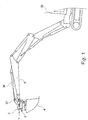
- Fig. 1 shows, the quick coupler 1 between the free end of the boom 5 of an excavator 30 and the tool to be mounted on it 4 are mounted, said attachment tool 4 in Fig. 1 is designed as a grave spoon, but in a conventional manner, of course, other corresponding construction, handling or demolition tools, for example in the form of clamshell, demolition tongs, scissors or the like may include.
- Said quick coupler 1 is in this case on the one hand by means of a handle-side coupler part 2 pivotally mounted to a lying, aligned transversely to the longitudinal axis of the boom stem 5 pivot axis of said boom arm 5, so that the quick coupler 1 together with the attached tool 4, for example by means of a pressure medium cylinder 36 and an intermediate swivel piece 37 can be pivoted relative to the extension arm 5.
- said quick coupler can be mounted on the attachment tool 4 and / or an intermediate rotary drive.
- a locking receptacle 10 include the two Locking parts, for example in the form of locking axes 13 and 14 on the other, preferably tool-side coupler part 3 hooked or can be brought into engagement.
- FIG. 2 shows the Ankuppelage 6 and the locking receptacle 10 each have a mouth-shaped, open to one side receptacle into which the locking axles 13 and 14 can retract, which may be formed by transverse bolts or locking bolts, see.
- Fig. 2 shows the Ankuppelage 6 and the locking receptacle 10 each have a mouth-shaped, open to one side receptacle into which the locking axles 13 and 14 can retract, which may be formed by transverse bolts or locking bolts, see.
- Fig. 2 shows the Ankuppelage 6 and the locking receptacle 10 each have a mouth-shaped, open to one side receptacle into which the locking axles 13 and 14 can retract, which may be formed by transverse bolts or locking bolts, see.
- Fig. 2 shows the Ankuppelage 6 and the locking receptacle 10 each have a mouth-shaped, open to one side receptacle into which the locking axles 13 and 14 can retract, which
- the Ankuppelage 6 and the locking receptacle 10 are advantageously arranged and configured such that when a first locking axle 13 of a coupler part 3 is retracted or hooked into the preferably hook-shaped Ankuppelage 6 of the other coupler part 2, the two coupler parts can be pivoted to each other in such a way that the Ankuppelage 6 and the locking shaft 13 received therein form the axis of rotation and can retract the second locking shaft 14 in the locking receptacle 10 by the corresponding pivoting movement, so that the two coupler parts 2 and 3 are coupled together in a two-stage coupling process can.
- the Ankuppelage 6 is hooked to the first locking shaft 13 to then by pivoting the two coupler parts 2 and 3 relative to each other - which can be done for example by actuation of the aforementioned pivoting cylinder 36 - the locking receptacle 10 can be brought into engagement with the second locking axis 14.
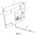
- a locking element 11 is provided, for example in the form of a locking wedge, which can be moved on the opening side of the locking receptacle 10 in front of the locking shaft 14 received therein, cf. Fig. 3 ,
- a tool 15 can advantageously be attached.
- the coupling receptacle 6 is advantageously associated with a securing element 25 which secures or locks the locking axis 13 in the coupling receptacle 6 and prevents the locking axis 13 from being moved out of the coupling receptacle 6.
- Said securing element 25 may comprise a movable latch part which can be retracted into the area of the open end of the coupling receptacle 6, cf. Fig. 6 (b) ,
- two locking elements 11 of the locking receptacle 10 are advantageously assigned to lock therein the second locking axis 14, wherein said locking elements 11 may be advantageously arranged on opposite edge or side portions of the coupler body 7.
- two securing elements 25 may be associated with the coupling receptacle 6 in order to lock the first locking axis 14 therein, wherein said securing elements 25 may advantageously be arranged on opposite edge or side sections of the coupler body 7.
- the two locking elements 11 and the two securing elements 25 can advantageously be manually operated via a control gear 12, wherein each locking element 11 and securing element 25 may be assigned its own adjusting gear assembly, which can be synchronized with each other via the tool 15 to be applied or a synchronization shaft.
- each adjusting gear assembly of the adjusting gear 12 includes a rotary actuator 16 which is mounted about a transverse axis approximately parallel to the longitudinal extent of the locking receptacle 10 and transversely to the longitudinal axis of the locking member 11 rotatably mounted on the coupler body 11, wherein advantageously the axes of rotation of the two rotary actuator parts 16 to each other can be aligned.
- an actuating link 17 is articulated, which, on the other hand, is articulated on the associated locking element 11. If the rotary actuator 16 is rotated, the said actuating link 17 converts the rotational movement into a displacement of the locking element 11.
- the said locking element 11 is for this purpose mounted longitudinally displaceable on the coupler body 7.
- a second rotary setting part 26 can be provided, which can be formed separately from the first rotary setting part 16, but can also be combined with the mentioned rotary setting part 16.
- An actuation link 27 directs the securing element 25 against the aforementioned rotary setting part 26 in order to convert a rotation of the rotary setting part 16 into a translatory sliding movement of the securing element 25.
- the rotary actuator parts 16 and 26 extend on opposite sides of the axis of rotation, so that the locking and securing elements 11 and 25 are moved in opposite directions to each other when the rotary actuator parts are rotated in one direction of rotation, see. in comparison to each other Fig. 6 (a) and Fig. 6 (b) ,
- a tension link 18 is articulated articulated to said rotary actuator 16 and / or the rotary actuator 26, on the other hand, is displaceably guided on the coupler body 7. More precisely, the said tension control arm 18 is slidably guided on a rotatable stop 19, so that the tension link 18 can be displaced against the stop 19 during rotational movements of the rotary actuating part 16, wherein the stop 19 can rotate simultaneously in order to take into account the pivoting of the tension link 18 ,
- Said tensioning arm 18 is prestressed by a spring device 20, said spring device 20 being able to be arranged between said stop 19 and a shoulder of the tensioning link 18, for example in the form of a helical spring which is pushed over the tensioning link 18.
- the clamping force of the spring device 20 attempts to move the tension link 18 in one direction, which causes a rotational bias on the rotary actuator 16 and / or the rotary actuator 26.
- the spring device 20 and the tensioning link 18 are in this case arranged on the rotary adjusting part 16 that when turning the rotary actuator 16 from the unlocked position into the locking position and vice versa from the locking position to the unlocked position a dead center position is run over and the spring device 20, the rotary actuator 16 once trying to bias in one direction and the other in the other direction.
- the spring device 20 biases the rotary actuator 16 on the one hand the unlocked end position and on the other hand in the locked end position before, depending on which side of the said dead center has been run over.
- the spring device 20 and the tension link 18 on the one hand and the actuating link 17 on the other hand on opposite sides of the rotary actuator 16 are arranged to achieve an overall very slim design of the adjusting gear assemblies.
- the two Stellgetriebebau phenomenon can be synchronized by a drive or synchronization shaft 21 with each other, which couples the two rotary actuator members 16 together so that they are rotated in synchronization with each other.
- Said drive shaft 21 can be permanently installed or alternatively be formed by the actuation tool 15 to be attached, which can be inserted from one side in both rotary actuator parts 16 and 26 respectively.
- the rotary actuator parts 16 and 26 can for this purpose have a torque-transmitting plug-in recess, for example in the form of a polygonal hole or a profile shaft recess.
- the rotary actuator parts 16 and 26 can advantageously be arranged such that the actuating tool 15 can be inserted through a through-passage 22 which can be inserted into one of the side flanges of the coupler part 3 to be coupled, cf. Fig. 2 ,
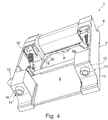
- FIGS. 4 and 5 show the coupler body 7 of the coupler part 2 has a central recess 8 which is provided between the Ankuppel- and locking receptacles 6 and 10 and extends on the underside of the coupler body 7, see.
- FIGS. 4 and 5 show the coupler body 7 of the coupler part 2 has a central recess 8 which is provided between the Ankuppel- and locking receptacles 6 and 10 and extends on the underside of the coupler body 7, see.
- FIGS. 4 and 5 show the coupler body 7 of the coupler part 2 has a central recess 8 which is provided between the Ankuppel- and locking receptacles 6 and 10 and extends on the underside of the coupler body 7, see.
- FIGS. 4 and 5 show the coupler body 7 of the coupler part 2 has a central recess 8 which is provided between the Ankuppel- and locking receptacles 6 and 10 and extends on the underside of the coupler body 7, see.
- Said recess 8 is thereby framed, on the one hand by said coupling and locking receptacles 6 and 10 and the sections of the coupler body 7 forming these, and on the other hand by longitudinally extending longitudinal webs which form the coupler body 7 on the right and on the left connect both Ankuppel- and locking receptacles 6 and 10 together.
- the central region of the coupler body 7 is thus recessed, said recess 8 can extend over more than two thirds of the width of the coupler body 7 and over at least half of the length in the sense of spacing between the two Ankuppel- and locking receptacles 6 and 10.
- said recess 8 may form a central cup-shaped or trough-shaped recess in the underside of the coupler body 7, which is moved to the coupler part 3 to be joined during coupling, said recess 8 laterally to the right and left of strengthening, stiffening structure thickening, in particular in the form may be bordered by edge beads 23.
- Said edge beads 23 may form an elongate hollow box profile or else consist of a solid longitudinal member or web, so that the thickness of the coupler body on the lateral edge beads 23 increases massively with respect to the recessed central region and in particular is a multiple of the thickness in the central region.
- FIG. 5 show the central recess 8 can be bordered along three sides of such edge beads, wherein left and right arranged edge beads 23l and 23r be at least partially formed as a hollow box profile and / or can accommodate the adjusting gear sections of the adjusting gear 12.
- a transversely extending edge bead 23q can form the receiving jaw 6 and / or laterally shaped peripheral mouthpieces 6 connect together and be formed, for example in the form of a solid half-shell profile.
- a structural plate 24 for example in the form of a sheet metal plate, in particular sheet steel plate or a thin, approximately planar structural part, which may also be designed wandwerk- or net or mesh-like.
- a central through-hole 8a may be provided, which may form part of said recess 8 and in the area of said recess 8 extends from the bottom to the top of the coupler body 7.
- Said passage recess 8a may, for example, have an extent whose inside diameter is more than 50% or even more than 66% of the width of the entire coupler body and / or its clear length more than 33% or even more than 50% of the spacing of the coupling and Locking recordings is.
- the actuating mechanism 12 extends laterally to the right and left of said recess 8 and leaves the said recess 8 free, so that existing coupling coupler 3 existing hydraulic couplings 9 collision-free retract into the recess 8 and between the two Ankuppel- and locking receptacles 6 and 10th can retract.
- Said actuating gear 12 may extend at least partially in the interior of said edge-side edge beads 23l and 23r, wherein alternatively or additionally said edge beads 23 may also have recesses in the region of which said actuating gears 12 are exposed.
- the quick coupler is advantageously characterized by the fact that both the locking receptacle 10 associated locking member 11 and a movable securing member 25 which is associated with the Ankuppelfact 6 for securing the first locking member 13 received therein, actuated by the common drive shaft 21 and each over an actuating handlebars 17, 27 are articulated on a rotatably connected to the common drive shaft 21 rotary actuator part 16, 26, so that the Verriegelungslement 11 and the securing element 25 by rotating the common drive shaft 21 in a rotational direction to each other in opposite directions.
- said drive shaft 21 extends transversely over the coupler body 7 between the coupling receptacle 6 and the locking receptacle 10 and a side wall 7s of the coupler body 7 has a through-passage 28, through which the drive shaft 21 extends to an outer side of the coupler body 7 extends and / or the hand tool with the drive shaft 21 can be coupled.
- the Ankuppelage 6 forms a mouth-shaped blind groove with a NutlCodesachse 29, which is facing away from the locking receptacle 10 to a side, wherein the NutlHarsachse 29 to a control axis 25a of the fuse element 25 and / or a connecting plane 30 which goes through both the Ankuppelage 6 and through the locking receptacle 10 is inclined at an acute angle.
- the rotary actuator parts 16, 26, on which the locking element 11 on the one hand and the securing element 25 are hinged on the other hand extend on opposite sides of the drive shaft 11 and are arranged such that the actuating links 17, 27 of the locking element 11 and When the drive shaft 21 is rotated, the securing element 25 can be overstretched from the unlocking position into the locking position and in each case run over a dead center.
- the quick coupler can be characterized in that the securing element 25 is coupled via the operating link 27 and the rotary actuator 26 at least substantially free of play to the rotational movement of the drive shaft 21 and the rotational movement of the drive shaft 21 is positively controlled converted into an actuating movement of the securing element 25 while the locking member 11 relative to the drive shaft 21 has a limited clearance, which is preferably associated with a biasing device for biasing in an end position of clearance.
- a monitoring sensor system 31 for monitoring the locking has at least one rotary position sensor 32 for monitoring the reaching of an interlocking rotational position of the drive shaft 21 and two pick-up sensors 33, 34, which are assigned on the one hand the Ankuppelage 6 and on the other hand, the locking receptacle 10 and the presence the first and second locking part 13, 14 in the Ankuppelage 6 and the locking receptacle 10 monitor.
- the common drive shaft 21 has a Stellaktoran gleich for connecting a foreign energy actuated Stellaktors 35 for rotating the drive shaft 21.
- the quick coupler can be characterized in that the Stellaktor 35 includes at least one pressure medium cylinder 36 which extends substantially parallel to a connection plane which goes through both the Ankuppelage 6 and through the locking receptacle 10.
- the quick coupler can be characterized in that the Stellaktor 35 includes an electric motor and / or an electric Stellaktor.
Landscapes
- Engineering & Computer Science (AREA)
- Mechanical Engineering (AREA)
- Mining & Mineral Resources (AREA)
- Civil Engineering (AREA)
- General Engineering & Computer Science (AREA)
- Structural Engineering (AREA)
- Shovels (AREA)
- Earth Drilling (AREA)
Applications Claiming Priority (2)
| Application Number | Priority Date | Filing Date | Title |
|---|---|---|---|
| DE202017001245 | 2017-03-08 | ||
| DE202017001992.2U DE202017001992U1 (de) | 2017-03-08 | 2017-04-13 | Schnellkuppler |
Publications (3)
| Publication Number | Publication Date |
|---|---|
| EP3382103A2 true EP3382103A2 (fr) | 2018-10-03 |
| EP3382103A3 EP3382103A3 (fr) | 2019-02-27 |
| EP3382103B1 EP3382103B1 (fr) | 2022-06-29 |
Family
ID=62716952
Family Applications (1)
| Application Number | Title | Priority Date | Filing Date |
|---|---|---|---|
| EP18160660.9A Active EP3382103B1 (fr) | 2017-03-08 | 2018-03-08 | Système de raccord rapide |
Country Status (6)
| Country | Link |
|---|---|
| EP (1) | EP3382103B1 (fr) |
| DE (1) | DE202017001992U1 (fr) |
| DK (1) | DK3382103T3 (fr) |
| ES (1) | ES2923181T3 (fr) |
| HU (1) | HUE060147T2 (fr) |
| PL (1) | PL3382103T3 (fr) |
Cited By (2)
| Publication number | Priority date | Publication date | Assignee | Title |
|---|---|---|---|---|
| US20220316185A1 (en) * | 2021-03-31 | 2022-10-06 | Nabtesco Corporation | Drive transmission device and construction machine |
| CN119195251A (zh) * | 2024-11-12 | 2024-12-27 | 中国三冶集团有限公司 | 一种用于挖掘机的液压式快速联接器 |
Families Citing this family (4)
| Publication number | Priority date | Publication date | Assignee | Title |
|---|---|---|---|---|
| DE202020100794U1 (de) * | 2020-02-14 | 2021-05-17 | Kinshofer Gmbh | Hydraulisches Anbaugerät sowie Baumaschine mit einem solchen Anbaugerät |
| DE102023114523A1 (de) | 2023-06-02 | 2024-12-05 | OilQuick Deutschland KG | Tiltrotator |
| DE102023119932A1 (de) | 2023-07-27 | 2025-01-30 | OilQuick Deutschland KG | Schnellwechselsystem |
| DE202023104217U1 (de) | 2023-07-27 | 2024-11-04 | OilQuick Deutschland KG | Schnellwechselsystem |
Family Cites Families (14)
| Publication number | Priority date | Publication date | Assignee | Title |
|---|---|---|---|---|
| US3876091A (en) * | 1974-07-26 | 1975-04-08 | Rivinius Inc | Implement connecting coupling mechanism |
| GB8625778D0 (en) * | 1986-10-28 | 1986-12-03 | Knackstedt J S | Connector |
| JP2537066Y2 (ja) * | 1991-11-15 | 1997-05-28 | 油谷重工株式会社 | バケット脱着装置 |
| US5419673A (en) * | 1993-03-11 | 1995-05-30 | Memo Industrial Planning, Inc. | Quick disconnect apparatus for tractor front loader |
| PT1318242E (pt) * | 2001-12-06 | 2007-01-31 | Geith Patents Ltd | Engate para acoplar um acessório a um braço de escavadora e sistema de comando deste engate |
| US7779716B2 (en) * | 2004-10-22 | 2010-08-24 | Ati Industrial Automation, Inc. | Quick disconnect tooling apparatus |
| WO2007038960A1 (fr) * | 2005-10-03 | 2007-04-12 | Cos.Mec S.R.L. | Systeme de securite permettant d'eviter tout desserrage imprevu d'un outil par rapport a un dispositif a attache rapide raccorde sur un bras de manœuvre d'un engin de terrassement. |
| JP2007146582A (ja) * | 2005-11-30 | 2007-06-14 | Shin Caterpillar Mitsubishi Ltd | 作業車両のクイックカプラ |
| DK1852555T3 (da) | 2006-05-02 | 2012-10-08 | Kinshofer Gmbh | Sikkerhedslåseindretning til en lynkobling |
| US8974137B2 (en) * | 2011-12-22 | 2015-03-10 | Caterpillar Inc. | Quick coupler |
| GB2505703A (en) * | 2012-09-10 | 2014-03-12 | Geith Internat Ltd | A locking mechanism for use in a quick hitch coupling |
| DE202014001328U1 (de) | 2014-02-13 | 2015-05-15 | Kinshofer Gmbh | Schnellkuppler |
| DE102014119748A1 (de) * | 2014-12-31 | 2016-06-30 | Lehnhoff Hartstahl Gmbh & Co. Kg | Schnellwechsler und Adapter einer Schnellwechselvorrichtung |
| DE102015210860A1 (de) * | 2015-06-12 | 2016-12-15 | Lehnhoff Hartstahl Gmbh & Co. Kg | Schnellwechsler |
-
2017
- 2017-04-13 DE DE202017001992.2U patent/DE202017001992U1/de active Active
-
2018
- 2018-03-08 HU HUE18160660A patent/HUE060147T2/hu unknown
- 2018-03-08 EP EP18160660.9A patent/EP3382103B1/fr active Active
- 2018-03-08 PL PL18160660.9T patent/PL3382103T3/pl unknown
- 2018-03-08 ES ES18160660T patent/ES2923181T3/es active Active
- 2018-03-08 DK DK18160660.9T patent/DK3382103T3/da active
Cited By (3)
| Publication number | Priority date | Publication date | Assignee | Title |
|---|---|---|---|---|
| US20220316185A1 (en) * | 2021-03-31 | 2022-10-06 | Nabtesco Corporation | Drive transmission device and construction machine |
| US12460381B2 (en) * | 2021-03-31 | 2025-11-04 | Nabtesco Corporation | Drive transmission device and construction machine |
| CN119195251A (zh) * | 2024-11-12 | 2024-12-27 | 中国三冶集团有限公司 | 一种用于挖掘机的液压式快速联接器 |
Also Published As
| Publication number | Publication date |
|---|---|
| DE202017001992U1 (de) | 2018-06-11 |
| EP3382103B1 (fr) | 2022-06-29 |
| ES2923181T3 (es) | 2022-09-26 |
| EP3382103A3 (fr) | 2019-02-27 |
| PL3382103T3 (pl) | 2022-11-07 |
| DK3382103T3 (da) | 2022-08-22 |
| HUE060147T2 (hu) | 2023-02-28 |
Similar Documents
| Publication | Publication Date | Title |
|---|---|---|
| EP3382103B1 (fr) | Système de raccord rapide | |
| EP4263318B1 (fr) | Attelage ferroviaire automatique et procédé de désaccouplement d'un attelage ferroviaire automatique | |
| DE3924313C2 (de) | Schnellwechselvorrichtung für ein Frontladegerät | |
| EP4263319B1 (fr) | Attelage de traction automatique | |
| EP3715535B1 (fr) | Dispositif de changement rapide pour outils de machines de construction | |
| DE9318847U1 (de) | Teleskopierbarer Ausleger mit mehrstufigem Hydraulikzylinder | |
| EP2216204B1 (fr) | Galerie pour véhicules automobiles | |
| DE102005037105C5 (de) | Adapter für ein Arbeitsgerät als Teil einer Schnellwechselvorrichtung und Schnellwechselvorrichtung | |
| EP2248753B1 (fr) | Grue dotée d'une capacité à surmonter un point mort | |
| EP2403998B1 (fr) | Equipement pour engins de construction | |
| DE202021101016U1 (de) | Schnellwechsler für Baumaschinenwerkzeuge | |
| EP2959061B1 (fr) | Barrière de séparation de voie et système de retenue de véhicule équipé d'une telle barrière de séparation de voie | |
| EP2810590B1 (fr) | Support pour arbre | |
| EP1886547A2 (fr) | Liaison d'un bras de levage sur un arbre de levage d'un système d'attelage trois points | |
| DE102014101001B4 (de) | Schnellwechselvorrichtung für ein Baugerät mit Ausleger | |
| EP4278053A1 (fr) | Logement d'élément | |
| EP3276112B1 (fr) | Dispositif de verrouillage de porte | |
| DE102012006591A1 (de) | Verriegelungsvorrichtung | |
| DE2852670C2 (fr) | ||
| EP2412876A2 (fr) | Agencement de chargeur frontal | |
| DE102019125861A1 (de) | Schnellwechsler | |
| EP1190906A2 (fr) | Dispositif de fixation, en particulier pour un coffre de toit | |
| EP1651818A1 (fr) | Dispositif de fixation interchangeable d'un outil, par ex, d'un godet d'excavatrice, sur le bras d'une excavatrice ou un vehicule | |
| EP3821687B1 (fr) | Dispositif de couplage | |
| DE102009045440A1 (de) | Panikverschluss mit schwenkbarem Stangengriff |
Legal Events
| Date | Code | Title | Description |
|---|---|---|---|
| PUAI | Public reference made under article 153(3) epc to a published international application that has entered the european phase |
Free format text: ORIGINAL CODE: 0009012 |
|
| STAA | Information on the status of an ep patent application or granted ep patent |
Free format text: STATUS: THE APPLICATION HAS BEEN PUBLISHED |
|
| AK | Designated contracting states |
Kind code of ref document: A2 Designated state(s): AL AT BE BG CH CY CZ DE DK EE ES FI FR GB GR HR HU IE IS IT LI LT LU LV MC MK MT NL NO PL PT RO RS SE SI SK SM TR |
|
| AX | Request for extension of the european patent |
Extension state: BA ME |
|
| PUAL | Search report despatched |
Free format text: ORIGINAL CODE: 0009013 |
|
| AK | Designated contracting states |
Kind code of ref document: A3 Designated state(s): AL AT BE BG CH CY CZ DE DK EE ES FI FR GB GR HR HU IE IS IT LI LT LU LV MC MK MT NL NO PL PT RO RS SE SI SK SM TR |
|
| AX | Request for extension of the european patent |
Extension state: BA ME |
|
| RIC1 | Information provided on ipc code assigned before grant |
Ipc: E02F 3/36 20060101AFI20190122BHEP |
|
| STAA | Information on the status of an ep patent application or granted ep patent |
Free format text: STATUS: REQUEST FOR EXAMINATION WAS MADE |
|
| 17P | Request for examination filed |
Effective date: 20190821 |
|
| RBV | Designated contracting states (corrected) |
Designated state(s): AL AT BE BG CH CY CZ DE DK EE ES FI FR GB GR HR HU IE IS IT LI LT LU LV MC MK MT NL NO PL PT RO RS SE SI SK SM TR |
|
| RAP1 | Party data changed (applicant data changed or rights of an application transferred) |
Owner name: QILQUICK DEUTSCHLAND GMBH |
|
| RAP1 | Party data changed (applicant data changed or rights of an application transferred) |
Owner name: OILQUICK DEUTSCHLAND KG |
|
| GRAP | Despatch of communication of intention to grant a patent |
Free format text: ORIGINAL CODE: EPIDOSNIGR1 |
|
| STAA | Information on the status of an ep patent application or granted ep patent |
Free format text: STATUS: GRANT OF PATENT IS INTENDED |
|
| INTG | Intention to grant announced |
Effective date: 20220408 |
|
| GRAS | Grant fee paid |
Free format text: ORIGINAL CODE: EPIDOSNIGR3 |
|
| GRAA | (expected) grant |
Free format text: ORIGINAL CODE: 0009210 |
|
| STAA | Information on the status of an ep patent application or granted ep patent |
Free format text: STATUS: THE PATENT HAS BEEN GRANTED |
|
| AK | Designated contracting states |
Kind code of ref document: B1 Designated state(s): AL AT BE BG CH CY CZ DE DK EE ES FI FR GB GR HR HU IE IS IT LI LT LU LV MC MK MT NL NO PL PT RO RS SE SI SK SM TR |
|
| REG | Reference to a national code |
Ref country code: CH Ref legal event code: EP |
|
| REG | Reference to a national code |
Ref country code: AT Ref legal event code: REF Ref document number: 1501436 Country of ref document: AT Kind code of ref document: T Effective date: 20220715 |
|
| REG | Reference to a national code |
Ref country code: IE Ref legal event code: FG4D Free format text: LANGUAGE OF EP DOCUMENT: GERMAN |
|
| REG | Reference to a national code |
Ref country code: DE Ref legal event code: R096 Ref document number: 502018010023 Country of ref document: DE |
|
| REG | Reference to a national code |
Ref country code: NL Ref legal event code: FP |
|
| REG | Reference to a national code |
Ref country code: DK Ref legal event code: T3 Effective date: 20220818 |
|
| REG | Reference to a national code |
Ref country code: ES Ref legal event code: FG2A Ref document number: 2923181 Country of ref document: ES Kind code of ref document: T3 Effective date: 20220926 |
|
| REG | Reference to a national code |
Ref country code: FI Ref legal event code: FGE |
|
| REG | Reference to a national code |
Ref country code: NO Ref legal event code: T2 Effective date: 20220629 Ref country code: LT Ref legal event code: MG9D |
|
| REG | Reference to a national code |
Ref country code: SE Ref legal event code: TRGR |
|
| PG25 | Lapsed in a contracting state [announced via postgrant information from national office to epo] |
Ref country code: LT Free format text: LAPSE BECAUSE OF FAILURE TO SUBMIT A TRANSLATION OF THE DESCRIPTION OR TO PAY THE FEE WITHIN THE PRESCRIBED TIME-LIMIT Effective date: 20220629 Ref country code: HR Free format text: LAPSE BECAUSE OF FAILURE TO SUBMIT A TRANSLATION OF THE DESCRIPTION OR TO PAY THE FEE WITHIN THE PRESCRIBED TIME-LIMIT Effective date: 20220629 Ref country code: GR Free format text: LAPSE BECAUSE OF FAILURE TO SUBMIT A TRANSLATION OF THE DESCRIPTION OR TO PAY THE FEE WITHIN THE PRESCRIBED TIME-LIMIT Effective date: 20220930 Ref country code: BG Free format text: LAPSE BECAUSE OF FAILURE TO SUBMIT A TRANSLATION OF THE DESCRIPTION OR TO PAY THE FEE WITHIN THE PRESCRIBED TIME-LIMIT Effective date: 20220929 |
|
| REG | Reference to a national code |
Ref country code: SK Ref legal event code: T3 Ref document number: E 40424 Country of ref document: SK |
|
| PG25 | Lapsed in a contracting state [announced via postgrant information from national office to epo] |
Ref country code: RS Free format text: LAPSE BECAUSE OF FAILURE TO SUBMIT A TRANSLATION OF THE DESCRIPTION OR TO PAY THE FEE WITHIN THE PRESCRIBED TIME-LIMIT Effective date: 20220629 Ref country code: LV Free format text: LAPSE BECAUSE OF FAILURE TO SUBMIT A TRANSLATION OF THE DESCRIPTION OR TO PAY THE FEE WITHIN THE PRESCRIBED TIME-LIMIT Effective date: 20220629 |
|
| PG25 | Lapsed in a contracting state [announced via postgrant information from national office to epo] |
Ref country code: SM Free format text: LAPSE BECAUSE OF FAILURE TO SUBMIT A TRANSLATION OF THE DESCRIPTION OR TO PAY THE FEE WITHIN THE PRESCRIBED TIME-LIMIT Effective date: 20220629 Ref country code: RO Free format text: LAPSE BECAUSE OF FAILURE TO SUBMIT A TRANSLATION OF THE DESCRIPTION OR TO PAY THE FEE WITHIN THE PRESCRIBED TIME-LIMIT Effective date: 20220629 Ref country code: PT Free format text: LAPSE BECAUSE OF FAILURE TO SUBMIT A TRANSLATION OF THE DESCRIPTION OR TO PAY THE FEE WITHIN THE PRESCRIBED TIME-LIMIT Effective date: 20221031 Ref country code: EE Free format text: LAPSE BECAUSE OF FAILURE TO SUBMIT A TRANSLATION OF THE DESCRIPTION OR TO PAY THE FEE WITHIN THE PRESCRIBED TIME-LIMIT Effective date: 20220629 |
|
| PG25 | Lapsed in a contracting state [announced via postgrant information from national office to epo] |
Ref country code: IS Free format text: LAPSE BECAUSE OF FAILURE TO SUBMIT A TRANSLATION OF THE DESCRIPTION OR TO PAY THE FEE WITHIN THE PRESCRIBED TIME-LIMIT Effective date: 20221029 |
|
| REG | Reference to a national code |
Ref country code: HU Ref legal event code: AG4A Ref document number: E060147 Country of ref document: HU |
|
| REG | Reference to a national code |
Ref country code: DE Ref legal event code: R097 Ref document number: 502018010023 Country of ref document: DE |
|
| PG25 | Lapsed in a contracting state [announced via postgrant information from national office to epo] |
Ref country code: AL Free format text: LAPSE BECAUSE OF FAILURE TO SUBMIT A TRANSLATION OF THE DESCRIPTION OR TO PAY THE FEE WITHIN THE PRESCRIBED TIME-LIMIT Effective date: 20220629 |
|
| PLBE | No opposition filed within time limit |
Free format text: ORIGINAL CODE: 0009261 |
|
| STAA | Information on the status of an ep patent application or granted ep patent |
Free format text: STATUS: NO OPPOSITION FILED WITHIN TIME LIMIT |
|
| 26N | No opposition filed |
Effective date: 20230330 |
|
| P01 | Opt-out of the competence of the unified patent court (upc) registered |
Effective date: 20230502 |
|
| PG25 | Lapsed in a contracting state [announced via postgrant information from national office to epo] |
Ref country code: SI Free format text: LAPSE BECAUSE OF FAILURE TO SUBMIT A TRANSLATION OF THE DESCRIPTION OR TO PAY THE FEE WITHIN THE PRESCRIBED TIME-LIMIT Effective date: 20220629 |
|
| PG25 | Lapsed in a contracting state [announced via postgrant information from national office to epo] |
Ref country code: MC Free format text: LAPSE BECAUSE OF FAILURE TO SUBMIT A TRANSLATION OF THE DESCRIPTION OR TO PAY THE FEE WITHIN THE PRESCRIBED TIME-LIMIT Effective date: 20220629 |
|
| REG | Reference to a national code |
Ref country code: IE Ref legal event code: MM4A |
|
| PG25 | Lapsed in a contracting state [announced via postgrant information from national office to epo] |
Ref country code: IE Free format text: LAPSE BECAUSE OF NON-PAYMENT OF DUE FEES Effective date: 20230308 |
|
| PG25 | Lapsed in a contracting state [announced via postgrant information from national office to epo] |
Ref country code: BG Free format text: LAPSE BECAUSE OF FAILURE TO SUBMIT A TRANSLATION OF THE DESCRIPTION OR TO PAY THE FEE WITHIN THE PRESCRIBED TIME-LIMIT Effective date: 20220629 |
|
| PG25 | Lapsed in a contracting state [announced via postgrant information from national office to epo] |
Ref country code: BG Free format text: LAPSE BECAUSE OF FAILURE TO SUBMIT A TRANSLATION OF THE DESCRIPTION OR TO PAY THE FEE WITHIN THE PRESCRIBED TIME-LIMIT Effective date: 20220629 |
|
| PGFP | Annual fee paid to national office [announced via postgrant information from national office to epo] |
Ref country code: SE Payment date: 20250311 Year of fee payment: 8 |
|
| PGFP | Annual fee paid to national office [announced via postgrant information from national office to epo] |
Ref country code: DK Payment date: 20250321 Year of fee payment: 8 Ref country code: NL Payment date: 20250324 Year of fee payment: 8 Ref country code: FI Payment date: 20250320 Year of fee payment: 8 |
|
| PGFP | Annual fee paid to national office [announced via postgrant information from national office to epo] |
Ref country code: LU Payment date: 20250320 Year of fee payment: 8 |
|
| PGFP | Annual fee paid to national office [announced via postgrant information from national office to epo] |
Ref country code: HU Payment date: 20250310 Year of fee payment: 8 |
|
| PGFP | Annual fee paid to national office [announced via postgrant information from national office to epo] |
Ref country code: NO Payment date: 20250320 Year of fee payment: 8 |
|
| PGFP | Annual fee paid to national office [announced via postgrant information from national office to epo] |
Ref country code: AT Payment date: 20250319 Year of fee payment: 8 Ref country code: BE Payment date: 20250320 Year of fee payment: 8 |
|
| PGFP | Annual fee paid to national office [announced via postgrant information from national office to epo] |
Ref country code: FR Payment date: 20250324 Year of fee payment: 8 Ref country code: PL Payment date: 20250225 Year of fee payment: 8 Ref country code: CZ Payment date: 20250224 Year of fee payment: 8 |
|
| PGFP | Annual fee paid to national office [announced via postgrant information from national office to epo] |
Ref country code: SK Payment date: 20250225 Year of fee payment: 8 Ref country code: GB Payment date: 20250324 Year of fee payment: 8 |
|
| PGFP | Annual fee paid to national office [announced via postgrant information from national office to epo] |
Ref country code: TR Payment date: 20250226 Year of fee payment: 8 |
|
| PGFP | Annual fee paid to national office [announced via postgrant information from national office to epo] |
Ref country code: DE Payment date: 20250415 Year of fee payment: 8 |
|
| PGFP | Annual fee paid to national office [announced via postgrant information from national office to epo] |
Ref country code: ES Payment date: 20250416 Year of fee payment: 8 |
|
| PGFP | Annual fee paid to national office [announced via postgrant information from national office to epo] |
Ref country code: IT Payment date: 20250331 Year of fee payment: 8 |
|
| PGFP | Annual fee paid to national office [announced via postgrant information from national office to epo] |
Ref country code: CH Payment date: 20250401 Year of fee payment: 8 |
|
| PG25 | Lapsed in a contracting state [announced via postgrant information from national office to epo] |
Ref country code: CY Free format text: LAPSE BECAUSE OF FAILURE TO SUBMIT A TRANSLATION OF THE DESCRIPTION OR TO PAY THE FEE WITHIN THE PRESCRIBED TIME-LIMIT; INVALID AB INITIO Effective date: 20180308 |